EP3858034B1 - Neuabstimmung zur flexiblen ressourcenzuweisung - Google Patents
Neuabstimmung zur flexiblen ressourcenzuweisung Download PDFInfo
- Publication number
- EP3858034B1 EP3858034B1 EP19786429.1A EP19786429A EP3858034B1 EP 3858034 B1 EP3858034 B1 EP 3858034B1 EP 19786429 A EP19786429 A EP 19786429A EP 3858034 B1 EP3858034 B1 EP 3858034B1
- Authority
- EP
- European Patent Office
- Prior art keywords
- resource allocation
- communication
- narrowband
- tuning band
- tuning
- Prior art date
- Legal status (The legal status is an assumption and is not a legal conclusion. Google has not performed a legal analysis and makes no representation as to the accuracy of the status listed.)
- Active
Links
Images


Classifications
-
- H—ELECTRICITY
- H04—ELECTRIC COMMUNICATION TECHNIQUE
- H04W—WIRELESS COMMUNICATION NETWORKS
- H04W72/00—Local resource management
- H04W72/50—Allocation or scheduling criteria for wireless resources
- H04W72/53—Allocation or scheduling criteria for wireless resources based on regulatory allocation policies
-
- H—ELECTRICITY
- H04—ELECTRIC COMMUNICATION TECHNIQUE
- H04W—WIRELESS COMMUNICATION NETWORKS
- H04W72/00—Local resource management
- H04W72/04—Wireless resource allocation
-
- H—ELECTRICITY
- H04—ELECTRIC COMMUNICATION TECHNIQUE
- H04L—TRANSMISSION OF DIGITAL INFORMATION, e.g. TELEGRAPHIC COMMUNICATION
- H04L1/00—Arrangements for detecting or preventing errors in the information received
- H04L1/12—Arrangements for detecting or preventing errors in the information received by using return channel
- H04L1/16—Arrangements for detecting or preventing errors in the information received by using return channel in which the return channel carries supervisory signals, e.g. repetition request signals
- H04L1/18—Automatic repetition systems, e.g. Van Duuren systems
- H04L1/1829—Arrangements specially adapted for the receiver end
- H04L1/1854—Scheduling and prioritising arrangements
-
- H—ELECTRICITY
- H04—ELECTRIC COMMUNICATION TECHNIQUE
- H04L—TRANSMISSION OF DIGITAL INFORMATION, e.g. TELEGRAPHIC COMMUNICATION
- H04L25/00—Baseband systems
- H04L25/02—Details ; arrangements for supplying electrical power along data transmission lines
- H04L25/0202—Channel estimation
- H04L25/0224—Channel estimation using sounding signals
- H04L25/0226—Channel estimation using sounding signals sounding signals per se
-
- H—ELECTRICITY
- H04—ELECTRIC COMMUNICATION TECHNIQUE
- H04L—TRANSMISSION OF DIGITAL INFORMATION, e.g. TELEGRAPHIC COMMUNICATION
- H04L5/00—Arrangements affording multiple use of the transmission path
- H04L5/003—Arrangements for allocating sub-channels of the transmission path
- H04L5/0048—Allocation of pilot signals, i.e. of signals known to the receiver
- H04L5/005—Allocation of pilot signals, i.e. of signals known to the receiver of common pilots, i.e. pilots destined for multiple users or terminals
-
- H—ELECTRICITY
- H04—ELECTRIC COMMUNICATION TECHNIQUE
- H04L—TRANSMISSION OF DIGITAL INFORMATION, e.g. TELEGRAPHIC COMMUNICATION
- H04L5/00—Arrangements affording multiple use of the transmission path
- H04L5/003—Arrangements for allocating sub-channels of the transmission path
- H04L5/0048—Allocation of pilot signals, i.e. of signals known to the receiver
- H04L5/0051—Allocation of pilot signals, i.e. of signals known to the receiver of dedicated pilots, i.e. pilots destined for a single user or terminal
-
- H—ELECTRICITY
- H04—ELECTRIC COMMUNICATION TECHNIQUE
- H04L—TRANSMISSION OF DIGITAL INFORMATION, e.g. TELEGRAPHIC COMMUNICATION
- H04L5/00—Arrangements affording multiple use of the transmission path
- H04L5/003—Arrangements for allocating sub-channels of the transmission path
- H04L5/0053—Allocation of signalling, i.e. of overhead other than pilot signals
-
- H—ELECTRICITY
- H04—ELECTRIC COMMUNICATION TECHNIQUE
- H04L—TRANSMISSION OF DIGITAL INFORMATION, e.g. TELEGRAPHIC COMMUNICATION
- H04L5/00—Arrangements affording multiple use of the transmission path
- H04L5/003—Arrangements for allocating sub-channels of the transmission path
- H04L5/0078—Timing of allocation
- H04L5/0082—Timing of allocation at predetermined intervals
-
- H—ELECTRICITY
- H04—ELECTRIC COMMUNICATION TECHNIQUE
- H04W—WIRELESS COMMUNICATION NETWORKS
- H04W4/00—Services specially adapted for wireless communication networks; Facilities therefor
- H04W4/80—Services using short range communication, e.g. near-field communication [NFC], radio-frequency identification [RFID] or low energy communication
-
- H—ELECTRICITY
- H04—ELECTRIC COMMUNICATION TECHNIQUE
- H04W—WIRELESS COMMUNICATION NETWORKS
- H04W72/00—Local resource management
- H04W72/04—Wireless resource allocation
- H04W72/044—Wireless resource allocation based on the type of the allocated resource
- H04W72/0453—Resources in frequency domain, e.g. a carrier in FDMA
-
- H—ELECTRICITY
- H04—ELECTRIC COMMUNICATION TECHNIQUE
- H04L—TRANSMISSION OF DIGITAL INFORMATION, e.g. TELEGRAPHIC COMMUNICATION
- H04L5/00—Arrangements affording multiple use of the transmission path
- H04L5/0001—Arrangements for dividing the transmission path
- H04L5/0003—Two-dimensional division
- H04L5/0005—Time-frequency
- H04L5/0007—Time-frequency the frequencies being orthogonal, e.g. OFDM(A) or DMT
-
- H—ELECTRICITY
- H04—ELECTRIC COMMUNICATION TECHNIQUE
- H04W—WIRELESS COMMUNICATION NETWORKS
- H04W72/00—Local resource management
- H04W72/04—Wireless resource allocation
- H04W72/044—Wireless resource allocation based on the type of the allocated resource
- H04W72/0446—Resources in time domain, e.g. slots or frames
Definitions
- the following relates generally to wireless communications, and more specifically to retuning for flexible resource allocation.
- Wireless communications systems are widely deployed to provide various types of communication content such as voice, video, packet data, messaging, broadcast, and so on. These systems may be capable of supporting communication with multiple users by sharing the available system resources (e.g., time, frequency, and power).
- Examples of such multiple-access systems include fourth generation (4G) systems such as Long Term Evolution (LTE) systems, LTE-Advanced (LTE-A) systems, or LTE-A Pro systems, and fifth generation (5G) systems which may be referred to as New Radio (NR) systems.
- 4G systems such as Long Term Evolution (LTE) systems, LTE-Advanced (LTE-A) systems, or LTE-A Pro systems
- 5G systems which may be referred to as New Radio (NR) systems.
- a wireless multiple-access communications system may include a number of base stations or network access nodes, each simultaneously supporting communication for multiple communication devices, which may be otherwise known as user equipment (UE). Attention is drawn to US 2016/249327 A1 describing managing of narrowband regions of system bandwidths for devices with limited communications resources, such as machine type communication(s) devices and enhanced MTC devices.
- UE user equipment
- a method includes determining a set of downlink narrowband regions partitioned from a DL system bandwidth, determining a set of uplink narrowband regions partitioned from an UL system bandwidth, determining a mapping between the set of DL narrowband regions and the set of UL narrowband regions, and communicating with at least a base station using at least one of the mapped narrowband regions.
- an improved method, apparatuses and a computer-program as set forth in the independent claims, respectively, are provided, that support retuning for flexible resource allocation.
- Preferred embodiments of the invention are described in the dependent claims.
- some devices e.g., band limited (BL) or coverage enhancement (CE) UEs
- BL band limited
- CE coverage enhancement
- some devices may have limited transmitting and receiving capability, and may operate using a subset of a system bandwidth of a carrier (e.g., narrowbands).
- a carrier e.g., narrowbands
- such devices may retune portions of their receivers or transmitters to support frequency hopping or frequency diversity in transmissions.
- retuning may create challenges in efficient communication when transmitting and receiving capability is limited.
- an MTC UE may communicate over a narrowband (NB) of a wider system bandwidth.
- the narrowbands within the system bandwidth may span a fixed number of physical resource blocks (PRBs) (e.g., 6 PRBs).
- PRBs physical resource blocks
- the UE may be configured with a resource allocation with a flexible starting resource block (RB).
- RB flexible starting resource block
- a flexible starting PRB may be used to indicate a new resource allocation, and may be supported for band limited or coverage enhancement UEs.
- a UE may retune between consecutive transmission time intervals (TTIs) or subframes. For instance, the UE may retune between a subframe 'N' and subframe 'N+1', when a narrowband (i.e., tuning band or allocation located NB) containing the resource allocation changes between the two subframes.
- a UE may perform retuning (e.g., in uplink (UL) or downlink (DL)) when the resource allocation moves from a first narrowband to a second narrowband.
- the UE may perform retuning if a portion of the resource allocation is not fully contained within a narrowband, and the allocation changes between the subframes.
- the retuning band may be determined based on alignment of a starting RB of the resource allocation with a resource block group (RBG) boundary, a narrowband shift or resource allocation shift indicated from the network or base station, or a starting RB of the resource allocation.
- the UE may drop a portion of the communication, or establish a guard period between subsequent communications due to the time associated with retuning.
- the retuning time may be dependent on UE capability, and may be one or more symbols long.
- a method of wireless communication may include identifying, at a UE, a first resource allocation for a first communication in a first TTI and a second resource allocation for a second communication in a second, subsequent TTI, where the first resource allocation is associated with a first narrowband and the second resource allocation is associated with a second narrowband, and where a portion of the first resource allocation is located outside the first narrowband or a portion of the second resource allocation is located outside the second narrowband, determining that a first tuning band associated with the first resource allocation for the first TTI is different from a second tuning band associated with the second resource allocation for the second TTI, and retuning from the first tuning band to the second tuning band between the first communication and the second communication based on the determining.
- the apparatus may include a processor, memory in electronic communication with the processor, and instructions stored in the memory.
- the instructions may be executable by the processor to cause the apparatus to identify, at a UE, a first resource allocation for a first communication in a first TTI and a second resource allocation for a second communication in a second, subsequent TTI, where the first resource allocation is associated with a first narrowband and the second resource allocation is associated with a second narrowband, and where a portion of the first resource allocation is located outside the first narrowband or a portion of the second resource allocation is located outside the second narrowband, determine that a first tuning band associated with the first resource allocation for the first TTI is different from a second tuning band associated with the second resource allocation for the second TTI, and retune from the first tuning band to the second tuning band between the first communication and the second communication based on the determining.
- the apparatus may include means for identifying, at a UE, a first resource allocation for a first communication in a first TTI and a second resource allocation for a second communication in a second, subsequent TTI, where the first resource allocation is associated with a first narrowband and the second resource allocation is associated with a second narrowband, and where a portion of the first resource allocation is located outside the first narrowband or a portion of the second resource allocation is located outside the second narrowband, determining that a first tuning band associated with the first resource allocation for the first TTI is different from a second tuning band associated with the second resource allocation for the second TTI, and retuning from the first tuning band to the second tuning band between the first communication and the second communication based on the determining.
- a non-transitory computer-readable medium storing code for wireless communication is described.
- the code may include instructions executable by a processor to identify, at a UE, a first resource allocation for a first communication in a first TTI and a second resource allocation for a second communication in a second, subsequent TTI, where the first resource allocation is associated with a first narrowband and the second resource allocation is associated with a second narrowband, and where a portion of the first resource allocation is located outside the first narrowband or a portion of the second resource allocation is located outside the second narrowband, determine that a first tuning band associated with the first resource allocation for the first TTI is different from a second tuning band associated with the second resource allocation for the second TTI, and retune from the first tuning band to the second tuning band between the first communication and the second communication based on the determining.
- Some examples of the method, apparatuses, and non-transitory computer-readable medium described herein may further include operations, features, means, or instructions for determining the second tuning band based on the second resource allocation and a set of RBGs for the system bandwidth.
- determining the second tuning band may include operations, features, means, or instructions for determining a starting RB of the second tuning band based on an alignment of a starting RB of the second resource allocation with a boundary of an RBG of the set of RBGs.
- determining the second tuning band may include operations, features, means, or instructions for determining an ending RB of the second tuning band based on an alignment of an ending RB of the second resource allocation with a boundary of an RBG of the set of RBGs.
- determining the second tuning band may include operations, features, means, or instructions for determining the second tuning band to start from a lowest RB of the system bandwidth when the portion of the second resource allocation located outside the second narrowband includes one or more edge RBs at a lower end of the system bandwidth that may be not included in a narrowband of the system bandwidth.
- determining the second tuning band may include operations, features, means, or instructions for determining the second tuning band to end at a highest RB of the system bandwidth when the portion of the second resource allocation outside the second narrowband includes one or more edge RBs at an upper end of the system bandwidth that may be not included in a narrowband of the system bandwidth.
- determining the second tuning band may include operations, features, means, or instructions for determining the second tuning band to start from a lowest RB of the second resource allocation when the portion of the second resource allocation outside the second narrowband may be exclusive of one or more edge RBs at a lower end or an upper end of the system bandwidth that may be not included in a narrowband of the system bandwidth.
- determining the second tuning band may include operations, features, means, or instructions for determining the second tuning band to start at a starting RB of the second resource allocation, or end at an ending RB of the second resource allocation.
- Some examples of the method, apparatuses, and non-transitory computer-readable medium described herein may further include operations, features, means, or instructions for receiving, from a base station, control information indicating the first resource allocation, the second resource allocation, or both.
- the first tuning band corresponds to the first narrowband.
- the second tuning band corresponds to the second narrowband.
- Some examples of the method, apparatuses, and non-transitory computer-readable medium described herein may further include operations, features, means, or instructions for receiving one or more bits indicating a shift of the second narrowband and determining the second tuning band based on the shift.
- Some examples of the method, apparatuses, and non-transitory computer-readable medium described herein may further include operations, features, means, or instructions for receiving one or more bits indicating a shift of the second resource allocation relative to the second narrowband and determining the second tuning band based on the shift.
- the second tuning band starts at a starting RB of the second resource allocation.
- the second tuning band ends at an ending RB of the second resource allocation.
- identifying the second resource allocation may include operations, features, means, or instructions for receiving control information in a TTI prior to the second TTI, the control information including a grant for the second resource allocation.
- each of the first and second tuning bands may be composed of continuous frequency resources having a same size as the first or the second narrowband.
- the first narrowband and the second narrowband correspond to a common narrowband.
- the first tuning band corresponds to the common narrowband.
- the first narrowband may be different from the second narrowband.
- Some examples of the method, apparatuses, and non-transitory computer-readable medium described herein may further include operations, features, means, or instructions for identifying a configuration for transmitting a sounding reference signal (SRS) in the first TTI and refraining from transmitting the SRS based on determining the first tuning band may be different from the second tuning band.
- SRS sounding reference signal
- Some examples of the method, apparatuses, and non-transitory computer-readable medium described herein may further include operations, features, means, or instructions for identifying a configuration for transmitting a SRS in the first TTI, where a portion of the SRS may be outside the second tuning band and refraining from transmitting the SRS based on identifying that the portion of the SRS may be outside the second tuning band.
- Some examples of the method, apparatuses, and non-transitory computer-readable medium described herein may further include operations, features, means, or instructions for identifying a configuration for a SRS in the first TTI, where a portion of the SRS may be outside the second tuning band, establishing a guard period between the first communication in the first TTI and the second communication in the second TTI and transmitting the SRS based on the establishing.
- Some examples of the method, apparatuses, and non-transitory computer-readable medium described herein may further include operations, features, means, or instructions for establishing a guard period between the first communication in the first TTI and the second communication in the second TTI.
- establishing the guard period may include operations, features, means, or instructions for puncturing one or more symbols of the second communication based on the retuning.
- the puncturing may be based on determining that the first and second communications may be downlink communications.
- the puncturing may be based on determining that the first communication may be an uplink communication and the second communication may be a downlink communication.
- the UE may be configured for monitoring a control channel within the first narrowband.
- Some examples of the method, apparatuses, and non-transitory computer-readable medium described herein may further include operations, features, means, or instructions for refraining from monitoring the control channel in the second TTI based on determining that at least a portion of the control channel does not overlap with the second tuning band.
- Some examples of the method, apparatuses, and non-transitory computer-readable medium described herein may further include operations, features, means, or instructions for identifying a portion of the control channel within the first narrowband that overlaps in frequency with the second tuning band and monitoring, in the second TTI, the portion of the control channel for control information.
- Some examples of the method, apparatuses, and non-transitory computer-readable medium described herein may further include operations, features, means, or instructions for monitoring an adjusted control channel in the second TTI for control information, the adjusted control channel being adjusted based on a relative offset of the second tuning band to the first narrowband.
- the second communication may be an uplink communication.
- some examples of the method, apparatuses, and non-transitory computer-readable medium described herein may include operations, features, means, or instructions for determining a center frequency of the second communication based on a coverage enhancement mode for the UE, a tuning time capability of the UE, a tuning configuration received from a base station, a reference signal configuration for the second communication, or a combination thereof.
- the determining the center frequency of the second communication may include operations, features, means, or instructions for setting the center frequency associated with the second communication to coincide with a center of the second tuning band.
- the determining the center frequency of the second communication may include operations, features, means, or instructions for setting the center frequency associated with the second communication to coincide with a center of the second resource allocation.
- the tuning configuration may be received from the base station in a unicast transmission or a broadcast transmission.
- the coverage enhancement mode for the UE may be one of a first coverage enhancement mode associated with a first amount of repetition or a second coverage enhancement mode associated with a second, larger amount of repetition.
- MTC machine type communication
- eMTC enhanced MTC
- a MTC device or MTC UE may be a low complexity, low cost device-relative to other user equipment (UEs)-and may be characterized by features such as low power operation, limited duplexing capability, and operation in environments with poor radio link conditions.
- UEs user equipment
- systems may be configured to account for operating characteristics of MTC devices.
- MTC UEs may use narrowband operation within a wider system bandwidth.
- a carrier may have a system bandwidth of 1.4, 3, 5, 10, 15, or 20 MHz, which may be composed of a plurality of narrowbands, and MTC UEs may be configured for operation over a single narrowband of the carrier at a time.
- a narrowband may include a set of contiguous frequency resources (e.g., 6 physical resource blocks (PRBs)), and a plurality of narrowbands (NBs) may be predefined or preconfigured in the network for the different bandwidths (e.g., 3 MHz, 5 MHz, etc.).
- PRBs physical resource blocks
- NBs narrowbands
- the frequency of transmitted signals may be changed periodically. This frequency hopping or shifting may help achieve frequency diversity and may help avoid narrowband interference.
- UEs may have a wideband operation capability and may receive the signal as the frequency is changed.
- Other devices such as some MTC UEs, may not be configured for wideband operation (e.g., operation over a full carrier bandwidth).
- the device may retune each time the frequency changes. This retuning may take a finite period of time and may result in increased network overhead.
- frequency retuning may occur in a period of less than a subframe, for example, on the order of a few symbol periods.
- UEs and network equipment may adjust their operation to support frequency hopping within a system.
- a machine type communication (MTC) UE may retune portions of its receive or transmit chain to support operation on various frequency bands. This retuning may introduce a delay, which the MTC UE and a base station may account for, and the duration of the retuning can be significantly reduced (e.g., on the order of symbol periods) if both the base station and UE anticipate or account for delays.
- a base station may refrain from transmitting to the MTC UE for a period of time (e.g., one, two, or three symbol periods) to account for a MTC UE's retuning.
- a base station may also account for frequency hopping delays for uplink communications. For instance, a base station may determine a retuning delay to decode uplink transmissions accordingly.
- a flexible starting physical resource block for indicating a new resource allocation may be supported for band limited (BL) or coverage enhancement (CE) UEs.
- the UE may retune between consecutive transmission time intervals (TTIs) or subframes. For instance, the UE may retune between a subframe 'N' and subframe 'N+1', when the narrowband containing the resource allocation changes between the two subframes.
- the UE may perform retuning from a first tuning band to a second tuning band (e.g., a newly defined retuning narrowband) if a portion of the resource allocation is not fully contained within a narrowband, and the allocation changes between the subframes.
- a second tuning band e.g., a newly defined retuning narrowband
- the newly defined retuning narrowband may be referred to as an allocation located retuning narrowband, and may be based in part on the new resource allocation, a set of resource block groups (RBGs) for the system bandwidth, an alignment of a starting or ending resource block (RB) of the new resource allocation with a RBG boundary, edge resource blocks at a lower or upper end of the system bandwidth not included in a narrowband of the system bandwidth, etc.
- the new retuning narrowband may be based in part on a shift for a narrowband associated with the new resource allocation for the subsequent communication in subframe 'N+1'.
- the retuning time may be dependent on UE capability, and may be one or more symbols long.
- the communication may introduce additional interference at the receiver end.
- a UE utilizing the newly defined retuning narrowband for uplink communications may cause additional interference at the base station (e.g., in the form of mirror image interference) in regards to transmissions from one or more other UEs utilizing a different narrowband (e.g., a predefined narrowband) or different parts of the narrowband.
- the additional interference may be mitigated through appropriate selection of a center frequency for the subsequent communication, based on a coverage enhancement mode for the UE, a tuning time capability of the UE, a tuning configuration received from a base station, or a reference signal configuration for the subsequent communication.
- the UE may refrain from communicating with the base station, or other UEs.
- the resource allocation for shared channel transmissions e.g., PDSCH or PUSCH
- the resource allocation for shared channel transmissions may lie outside a preconfigured narrowband of the system bandwidth.
- aspects of the disclosure are initially described in the context of a wireless communications system. Aspects of the disclosure are further illustrated by and described with reference to resource grids, apparatus diagrams, system diagrams, and flowcharts that relate to retuning for flexible resource allocation.
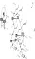
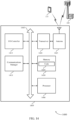
- FIG. 1 illustrates an example of a wireless communications system 100 that supports retuning for flexible resource allocation in accordance with aspects of the present disclosure.
- the wireless communications system 100 includes base stations 105, UEs 115, and a core network 130.
- the wireless communications system 100 may be a Long Term Evolution (LTE) network, an LTE-Advanced (LTE-A) network, an LTE-A Pro network, or a New Radio (NR) network.
- LTE Long Term Evolution
- LTE-A LTE-Advanced
- LTE-A Pro LTE-Advanced Pro
- NR New Radio
- wireless communications system 100 may support enhanced broadband communications, ultra-reliable (e.g., mission critical) communications, low latency communications, or communications with low-cost and low-complexity devices.
- ultra-reliable e.g., mission critical
- Base stations 105 may wirelessly communicate with UEs 115 via one or more base station antennas.
- Base stations 105 described herein may include or may be referred to by those skilled in the art as a base transceiver station, a radio base station, an access point, a radio transceiver, a NodeB, an eNodeB (eNB), a next-generation Node B or giga-nodeB (either of which may be referred to as a gNB), a Home NodeB, a Home eNodeB, or some other suitable terminology.
- Wireless communications system 100 may include base stations 105 of different types (e.g., macro or small cell base stations).
- the UEs 115 described herein may be able to communicate with various types of base stations 105 and network equipment including macro eNBs, small cell eNBs, gNBs, relay base stations, and the like.
- Each base station 105 may be associated with a particular geographic coverage area 110 in which communications with various UEs 115 is supported. Each base station 105 may provide communication coverage for a respective geographic coverage area 110 via communication links 125, and communication links 125 between a base station 105 and a UE 115 may utilize one or more carriers. Communication links 125 shown in wireless communications system 100 may include uplink transmissions from a UE 115 to a base station 105, or downlink transmissions from a base station 105 to a UE 115. Downlink transmissions may also be called forward link transmissions while uplink transmissions may also be called reverse link transmissions.
- the geographic coverage area 110 for a base station 105 may be divided into sectors making up only a portion of the geographic coverage area 110, and each sector may be associated with a cell.
- each base station 105 may provide communication coverage for a macro cell, a small cell, a hot spot, or other types of cells, or various combinations thereof.
- a base station 105 may be movable and therefore provide communication coverage for a moving geographic coverage area 110.
- different geographic coverage areas 110 associated with different technologies may overlap, and overlapping geographic coverage areas 110 associated with different technologies may be supported by the same base station 105 or by different base stations 105.
- the wireless communications system 100 may include, for example, a heterogeneous LTE/LTE-A/LTE-A Pro or NR network in which different types of base stations 105 provide coverage for various geographic coverage areas 110.
- the term "cell” refers to a logical communication entity used for communication with a base station 105 (e.g., over a carrier), and may be associated with an identifier for distinguishing neighboring cells (e.g., a physical cell identifier (PCID), a virtual cell identifier (VCID)) operating via the same or a different carrier.
- a carrier may support multiple cells, and different cells may be configured according to different protocol types (e.g., machine-type communication (MTC), narrowband Internet-of-Things (NB-IoT), enhanced mobile broadband (eMBB), or others) that may provide access for different types of devices.
- MTC machine-type communication
- NB-IoT narrowband Internet-of-Things
- eMBB enhanced mobile broadband
- the term "cell” may refer to a portion of a geographic coverage area 110 (e.g., a sector) over which the logical entity operates.
- UEs 115 may be dispersed throughout the wireless communications system 100, and each UE 115 may be stationary or mobile.
- a UE 115 may also be referred to as a mobile device, a wireless device, a remote device, a handheld device, or a subscriber device, or some other suitable terminology, where the "device” may also be referred to as a unit, a station, a terminal, or a client.
- a UE 115 may also be a personal electronic device such as a cellular phone, a personal digital assistant (PDA), a tablet computer, a laptop computer, or a personal computer.
- PDA personal digital assistant
- a UE 115 may also refer to a wireless local loop (WLL) station, an Internet of Things (IoT) device, an Internet of Everything (IoE) device, or an MTC device, or the like, which may be implemented in various articles such as appliances, vehicles, meters, or the like.
- WLL wireless local loop
- IoT Internet of Things
- IoE Internet of Everything
- MTC massive machine type communications
- Some UEs 115 may be low cost or low complexity devices, and may provide for automated communication between machines (e.g., via Machine-to-Machine (M2M) communication).
- M2M communication or MTC may refer to data communication technologies that allow devices to communicate with one another or a base station 105 without human intervention.
- M2M communication or MTC may include communications from devices that integrate sensors or meters to measure or capture information and relay that information to a central server or application program that can make use of the information or present the information to humans interacting with the program or application.
- Some UEs 115 may be designed to collect information or enable automated behavior of machines. Examples of applications for MTC devices include smart metering, inventory monitoring, water level monitoring, equipment monitoring, healthcare monitoring, wildlife monitoring, weather and geological event monitoring, fleet management and tracking, remote security sensing, physical access control, and transaction-based business charging.
- Some UEs 115 may be configured to employ operating modes that reduce power consumption, such as half-duplex communications (e.g., a mode that supports one-way communication via transmission or reception, but not transmission and reception simultaneously). In some examples, half-duplex communications may be performed at a reduced peak rate. Other power conservation techniques for UEs 115 include entering a power saving "deep sleep" mode when not engaging in active communications, or operating over a limited bandwidth (e.g., according to narrowband communications). In some cases, UEs 115 may be designed to support critical functions (e.g., mission critical functions), and a wireless communications system 100 may be configured to provide ultra-reliable communications for these functions.
- critical functions e.g., mission critical functions
- a UE 115 may also be able to communicate directly with other UEs 115 (e.g., using a peer-to-peer (P2P) or device-to-device (D2D) protocol).
- P2P peer-to-peer
- D2D device-to-device
- One or more of a group of UEs 115 utilizing D2D communications may be within the geographic coverage area 110 of a base station 105.
- Other UEs 115 in such a group may be outside the geographic coverage area 110 of a base station 105, or be otherwise unable to receive transmissions from a base station 105.
- groups of UEs 115 communicating via D2D communications may utilize a one-to-many (1:M) system in which each UE 115 transmits to every other UE 115 in the group.
- a base station 105 facilitates the scheduling of resources for D2D communications.
- D2D communications are carried out between UEs 115 without the involvement of a base station
- Base stations 105 may communicate with the core network 130 and with one another.
- base stations 105 may interface with the core network 130 through backhaul links 132 (e.g., via an S1, N2, N3, or other interface).
- Base stations 105 may communicate with one another over backhaul links 134 (e.g., via an X2, Xn, or other interface) either directly (e.g., directly between base stations 105) or indirectly (e.g., via core network 130).
- the core network 130 may provide user authentication, access authorization, tracking, Internet Protocol (IP) connectivity, and other access, routing, or mobility functions.
- the core network 130 may be an evolved packet core (EPC), which may include at least one mobility management entity (MME), at least one serving gateway (S-GW), and at least one Packet Data Network (PDN) gateway (P-GW).
- the MME may manage non-access stratum (e.g., control plane) functions such as mobility, authentication, and bearer management for UEs 115 served by base stations 105 associated with the EPC.
- User IP packets may be transferred through the S-GW, which itself may be connected to the P-GW.
- the P-GW may provide IP address allocation as well as other functions.
- the P-GW may be connected to the network operators IP services.
- the operators IP services may include access to the Internet, Intranet(s), an IP Multimedia Subsystem (IMS), or a Packet-Switched (PS) Streaming Service.
- IMS IP Multimedia Subsystem
- At least some of the network devices may include subcomponents such as an access network entity, which may be an example of an access node controller (ANC).
- an access network entity may communicate with UEs 115 through a number of other access network transmission entities, which may be referred to as a radio head, a smart radio head, or a transmission/reception point (TRP).
- TRP transmission/reception point
- various functions of each access network entity or base station 105 may be distributed across various network devices (e.g., radio heads and access network controllers) or consolidated into a single network device (e.g., a base station 105).
- Wireless communications system 100 may operate using one or more frequency bands, typically in the range of 300 MHz to 300 GHz.
- the region from 300 MHz to 3 GHz is known as the ultra-high frequency (UHF) region or decimeter band, since the wavelengths range from approximately one decimeter to one meter in length.
- UHF waves may be blocked or redirected by buildings and environmental features. However, the waves may penetrate structures sufficiently for a macro cell to provide service to UEs 115 located indoors. Transmission of UHF waves may be associated with smaller antennas and shorter range (e.g., less than 100 km) compared to transmission using the smaller frequencies and longer waves of the high frequency (HF) or very high frequency (VHF) portion of the spectrum below 300 MHz.
- HF high frequency
- VHF very high frequency
- Wireless communications system 100 may also operate in a super high frequency (SHF) region using frequency bands from 3 GHz to 30 GHz, also known as the centimeter band.
- SHF region includes bands such as the 5 GHz industrial, scientific, and medical (ISM) bands, which may be used opportunistically by devices that can tolerate interference from other users.
- ISM bands 5 GHz industrial, scientific, and medical bands
- Wireless communications system 100 may also operate in an extremely high frequency (EHF) region of the spectrum (e.g., from 30 GHz to 300 GHz), also known as the millimeter band.
- EHF extremely high frequency
- wireless communications system 100 may support millimeter wave (mmW) communications between UEs 115 and base stations 105, and EHF antennas of the respective devices may be even smaller and more closely spaced than UHF antennas. In some cases, this may facilitate use of antenna arrays within a UE 115.
- mmW millimeter wave
- the propagation of EHF transmissions may be subject to even greater atmospheric attenuation and shorter range than SHF or UHF transmissions. Techniques disclosed herein may be employed across transmissions that use one or more different frequency regions, and designated use of bands across these frequency regions may differ by country or regulating body.
- wireless communications system 100 may utilize both licensed and unlicensed radio frequency spectrum bands.
- wireless communications system 100 may employ License Assisted Access (LAA), LTE-Unlicensed (LTE-U) radio access technology, or NR technology in an unlicensed band such as the 5 GHz ISM band.
- LAA License Assisted Access
- LTE-U LTE-Unlicensed
- NR NR technology
- an unlicensed band such as the 5 GHz ISM band.
- wireless devices such as base stations 105 and UEs 115 may employ listen-before-talk (LBT) procedures to ensure a frequency channel is clear before transmitting data.
- LBT listen-before-talk
- operations in unlicensed bands may be based on a CA configuration in conjunction with CCs operating in a licensed band (e.g., LAA).
- Operations in unlicensed spectrum may include downlink transmissions, uplink transmissions, peer-to-peer transmissions, or a combination of these.
- Duplexing in unlicensed spectrum may be based on frequency division duplexing (FDD), time division duplexing (TDD), or a combination of both.
- FDD frequency division duplexing
- TDD time division duplexing
- base station 105 or UE 115 may be equipped with multiple antennas, which may be used to employ techniques such as transmit diversity, receive diversity, multiple-input multiple-output (MIMO) communications, or beamforming.
- wireless communications system 100 may use a transmission scheme between a transmitting device (e.g., a base station 105) and a receiving device (e.g., a UE 115), where the transmitting device is equipped with multiple antennas and the receiving devices are equipped with one or more antennas.
- MIMO communications may employ multipath signal propagation to increase the spectral efficiency by transmitting or receiving multiple signals via different spatial layers, which may be referred to as spatial multiplexing.
- the multiple signals may, for example, be transmitted by the transmitting device via different antennas or different combinations of antennas. Likewise, the multiple signals may be received by the receiving device via different antennas or different combinations of antennas.
- Each of the multiple signals may be referred to as a separate spatial stream, and may carry bits associated with the same data stream (e.g., the same codeword) or different data streams.
- Different spatial layers may be associated with different antenna ports used for channel measurement and reporting.
- MIMO techniques include single-user MIMO (SU-MIMO) where multiple spatial layers are transmitted to the same receiving device, and multiple-user MIMO (MU-MIMO) where multiple spatial layers are transmitted to multiple devices.
- SU-MIMO single-user MIMO
- MU-MIMO multiple-user MIMO
- Beamforming which may also be referred to as spatial filtering, directional transmission, or directional reception, is a signal processing technique that may be used at a transmitting device or a receiving device (e.g., a base station 105 or a UE 115) to shape or steer an antenna beam (e.g., a transmit beam or receive beam) along a spatial path between the transmitting device and the receiving device.
- Beamforming may be achieved by combining the signals communicated via antenna elements of an antenna array such that signals propagating at particular orientations with respect to an antenna array experience constructive interference while others experience destructive interference.
- the adjustment of signals communicated via the antenna elements may include a transmitting device or a receiving device applying certain amplitude and phase offsets to signals carried via each of the antenna elements associated with the device.
- the adjustments associated with each of the antenna elements may be defined by a beamforming weight set associated with a particular orientation (e.g., with respect to the antenna array of the transmitting device or receiving device, or with respect to some other orientation).
- a base station 105 may use multiple antennas or antenna arrays to conduct beamforming operations for directional communications with a UE 115. For instance, some signals (e.g., synchronization signals, reference signals, beam selection signals, or other control signals) may be transmitted by a base station 105 multiple times in different directions, which may include a signal being transmitted according to different beamforming weight sets associated with different directions of transmission. Transmissions in different beam directions may be used to identify (e.g., by the base station 105 or a receiving device, such as a UE 115) a beam direction for subsequent transmission and/or reception by the base station 105.
- some signals e.g., synchronization signals, reference signals, beam selection signals, or other control signals
- Transmissions in different beam directions may be used to identify (e.g., by the base station 105 or a receiving device, such as a UE 115) a beam direction for subsequent transmission and/or reception by the base station 105.
- Some signals may be transmitted by a base station 105 in a single beam direction (e.g., a direction associated with the receiving device, such as a UE 115).
- the beam direction associated with transmissions along a single beam direction may be determined based at least in in part on a signal that was transmitted in different beam directions.
- a UE 115 may receive one or more of the signals transmitted by the base station 105 in different directions, and the UE 115 may report to the base station 105 an indication of the signal it received with a highest signal quality, or an otherwise acceptable signal quality.
- a UE 115 may employ similar techniques for transmitting signals multiple times in different directions (e.g., for identifying a beam direction for subsequent transmission or reception by the UE 115), or transmitting a signal in a single direction (e.g., for transmitting data to a receiving device).
- a receiving device may try multiple receive beams when receiving various signals from the base station 105, such as synchronization signals, reference signals, beam selection signals, or other control signals.
- a receiving device may try multiple receive directions by receiving via different antenna subarrays, by processing received signals according to different antenna subarrays, by receiving according to different receive beamforming weight sets applied to signals received at a plurality of antenna elements of an antenna array, or by processing received signals according to different receive beamforming weight sets applied to signals received at a plurality of antenna elements of an antenna array, any of which may be referred to as "listening" according to different receive beams or receive directions.
- a receiving device may use a single receive beam to receive along a single beam direction (e.g., when receiving a data signal).
- the single receive beam may be aligned in a beam direction determined based on listening according to different receive beam directions (e.g., a beam direction determined to have a highest signal strength, highest signal-to-noise ratio, or otherwise acceptable signal quality based on listening according to multiple beam directions).
- the antennas of a base station 105 or UE 115 may be located within one or more antenna arrays, which may support MIMO operations, or transmit or receive beamforming.
- one or more base station antennas or antenna arrays may be co-located at an antenna assembly, such as an antenna tower.
- antennas or antenna arrays associated with a base station 105 may be located in diverse geographic locations.
- a base station 105 may have an antenna array with a number of rows and columns of antenna ports that the base station 105 may use to support beamforming of communications with a UE 115.
- a UE 115 may have one or more antenna arrays that may support various MIMO or beamforming operations.
- wireless communications system 100 may be a packet-based network that operate according to a layered protocol stack.
- PDCP Packet Data Convergence Protocol
- a Radio Link Control (RLC) layer may in some cases perform packet segmentation and reassembly to communicate over logical channels.
- RLC Radio Link Control
- a Medium Access Control (MAC) layer may perform priority handling and multiplexing of logical channels into transport channels.
- the MAC layer may also use hybrid automatic repeat request (HARQ) to provide retransmission at the MAC layer to improve link efficiency.
- HARQ hybrid automatic repeat request
- the Radio Resource Control (RRC) protocol layer may provide establishment, configuration, and maintenance of an RRC connection between a UE 115 and a base station 105 or core network 130 supporting radio bearers for user plane data.
- RRC Radio Resource Control
- PHY Physical
- UEs 115 and base stations 105 may support retransmissions of data to increase the likelihood that data is received successfully.
- HARQ feedback is one technique of increasing the likelihood that data is received correctly over a communication link 125.
- HARQ may include a combination of error detection (e.g., using a cyclic redundancy check (CRC)), forward error correction (FEC), and retransmission (e.g., automatic repeat request (ARQ)).
- FEC forward error correction
- ARQ automatic repeat request
- HARQ may improve throughput at the MAC layer in poor radio conditions (e.g., signal-to-noise conditions).
- a wireless device may support same-slot HARQ feedback, where the device may provide HARQ feedback in a specific slot for data received in a previous symbol in the slot. In other cases, the device may provide HARQ feedback in a subsequent slot, or according to some other time interval.
- the radio frames may be identified by a system frame number (SFN) ranging from 0 to 1023.
- SFN system frame number
- Each frame may include 10 subframes numbered from 0 to 9, and each subframe may have a duration of 1 ms.
- a subframe may be further divided into 2 slots each having a duration of 0.5 ms, and each slot may contain 6 or 7 modulation symbol periods (e.g., depending on the length of the cyclic prefix prepended to each symbol period). Excluding the cyclic prefix, each symbol period may contain 2048 sampling periods.
- a subframe may be the smallest scheduling unit of the wireless communications system 100, and may be referred to as a transmission time interval (TTI).
- TTI transmission time interval
- a smallest scheduling unit of the wireless communications system 100 may be shorter than a subframe or may be dynamically selected (e.g., in bursts of shortened TTIs (sTTIs) or in selected component carriers using sTTIs).
- a slot may further be divided into multiple mini-slots containing one or more symbols.
- a symbol of a mini-slot or a mini-slot may be the smallest unit of scheduling.
- Each symbol may vary in duration depending on the subcarrier spacing or frequency band of operation, for example.
- some wireless communications systems may implement slot aggregation in which multiple slots or mini-slots are aggregated together and used for communication between a UE 115 and a base station 105.
- carrier refers to a set of radio frequency spectrum resources having a defined physical layer structure for supporting communications over a communication link 125.
- a carrier of a communication link 125 may include a portion of a radio frequency spectrum band that is operated according to physical layer channels for a given radio access technology.
- Each physical layer channel may carry user data, control information, or other signaling.
- a carrier may be associated with a pre-defined frequency channel (e.g., an E-UTRA absolute radio frequency channel number (EARFCN)), and may be positioned according to a channel raster for discovery by UEs 115.
- E-UTRA absolute radio frequency channel number E-UTRA absolute radio frequency channel number
- Carriers may be downlink or uplink (e.g., in an FDD mode), or be configured to carry downlink and uplink communications (e.g., in a TDD mode).
- signal waveforms transmitted over a carrier may be made up of multiple sub-carriers (e.g., using multi-carrier modulation (MCM) techniques such as OFDM or DFT-s-OFDM).
- MCM multi-carrier modulation
- the organizational structure of the carriers may be different for different radio access technologies (e.g., LTE, LTE-A, LTE-A Pro, NR, etc.). For example, communications over a carrier may be organized according to TTIs or slots, each of which may include user data as well as control information or signaling to support decoding the user data.
- a carrier may also include dedicated acquisition signaling (e.g., synchronization signals or system information, etc.) and control signaling that coordinates operation for the carrier.
- acquisition signaling e.g., synchronization signals or system information, etc.
- control signaling that coordinates operation for the carrier.
- a carrier may also have acquisition signaling or control signaling that coordinates operations for other carriers.
- Physical channels may be multiplexed on a carrier according to various techniques.
- a physical control channel and a physical data channel may be multiplexed on a downlink carrier, for example, using time division multiplexing (TDM) techniques, frequency division multiplexing (FDM) techniques, or hybrid TDM-FDM techniques.
- control information transmitted in a physical control channel may be distributed between different control regions in a cascaded manner (e.g., between a common control region or common search space and one or more UE-specific control regions or UE-specific search spaces).
- a carrier may be associated with a particular bandwidth of the radio frequency spectrum, and in some examples the carrier bandwidth may be referred to as a "system bandwidth" of the carrier or the wireless communications system 100.
- the carrier bandwidth may be one of a number of predetermined bandwidths for carriers of a particular radio access technology (e.g., 1.4, 3, 5, 10, 15, 20, 40, or 80 MHz).
- each served UE 115 may be configured for operating over portions or all of the carrier bandwidth.
- some UEs 115 may be configured for operation using a narrowband protocol type that is associated with a predefined portion or range (e.g., set of subcarriers or resource blocks) within a carrier (e.g., "in-band" deployment of a narrowband protocol type).
- a resource element may include one symbol period (e.g., a duration of one modulation symbol) and one subcarrier, where the symbol period and subcarrier spacing are inversely related.
- the number of bits carried by each resource element may depend on the modulation scheme (e.g., the order of the modulation scheme).
- the more resource elements that a UE 115 receives and the higher the order of the modulation scheme the higher the data rate may be for the UE 115.
- a wireless communications resource may refer to a combination of a radio frequency spectrum resource, a time resource, and a spatial resource (e.g., spatial layers), and the use of multiple spatial layers may further increase the data rate for communications with a UE 115.
- Devices of the wireless communications system 100 may have a hardware configuration that supports communications over a particular carrier bandwidth, or may be configurable to support communications over one of a set of carrier bandwidths.
- the wireless communications system 100 may include base stations 105 and/or UEs 115 that can support simultaneous communications via carriers associated with more than one different carrier bandwidth.
- Wireless communications system 100 may support communication with a UE 115 on multiple cells or carriers, a feature which may be referred to as carrier aggregation (CA) or multi-carrier operation.
- a UE 115 may be configured with multiple downlink CCs and one or more uplink CCs according to a carrier aggregation configuration.
- Carrier aggregation may be used with both FDD and TDD component carriers.
- wireless communications system 100 may utilize enhanced component carriers (eCCs).
- eCC may be characterized by one or more features including wider carrier or frequency channel bandwidth, shorter symbol duration, shorter TTI duration, or modified control channel configuration.
- an eCC may be associated with a carrier aggregation configuration or a dual connectivity configuration (e.g., when multiple serving cells have a suboptimal or non-ideal backhaul link).
- An eCC may also be configured for use in unlicensed spectrum or shared spectrum (e.g., where more than one operator is allowed to use the spectrum).
- An eCC characterized by wide carrier bandwidth may include one or more segments that may be utilized by UEs 115 that are not capable of monitoring the whole carrier bandwidth or are otherwise configured to use a limited carrier bandwidth (e.g., to conserve power).
- an eCC may utilize a different symbol duration than other CCs, which may include use of a reduced symbol duration as compared with symbol durations of the other CCs.
- a shorter symbol duration may be associated with increased spacing between adjacent subcarriers.
- a device such as a UE 115 or base station 105, utilizing eCCs may transmit wideband signals (e.g., according to frequency channel or carrier bandwidths of 20, 40, 60, 80 MHz, etc.) at reduced symbol durations (e.g., 16.67 microseconds).
- a TTI in eCC may include one or multiple symbol periods. In some cases, the TTI duration (that is, the number of symbol periods in a TTI) may be variable.
- Wireless communications systems such as an NR system may utilize any combination of licensed, shared, and unlicensed spectrum bands, among others.
- the flexibility of eCC symbol duration and subcarrier spacing may allow for the use of eCC across multiple spectrums.
- NR shared spectrum may increase spectrum utilization and spectral efficiency, specifically through dynamic vertical (e.g., across the frequency domain) and horizontal (e.g., across the time domain) sharing of resources.
- FIG. 2 illustrates an example of a wireless communications system 200 that supports retuning for flexible resource allocation in accordance with aspects of the present disclosure.
- wireless communications system 200 may implement aspects of wireless communication system 100.
- wireless communications system 200 may include a base station 105-a and a UE 115-a, which may be examples of the devices described with reference to FIG. 1 .
- UE 115-a and base station 105-a may communicate using communication link 205.
- UE 115-a may be a BL or CE UE, a wireless sensor, wireless meter, or another MTC device.
- UE 115-a and base station 105-a may communicate over narrowbands of a wider system bandwidth, and may support the use of a flexible starting PRB for indicating a new resource allocation.
- a BL or CE UE such as UE 115-a, may support a bandwidth of up to 1.4 MHz, divided into a plurality of narrowbands.
- the narrowbands may include six (6) consecutive PRBs at predefined locations within the system bandwidth.
- the narrowbands of the system bandwidth may span portions of one or more RBGs, where each RBG may include one or more RBs. In some cases, the number of RBs within a RBG may vary with the operating bandwidth.
- resource allocation may be indicated differently for downlink and uplink communications. Further, indication of resource allocation may also differ based on the coverage enhancement mode or mode of operation (e.g., CEModeA, or CEModeB) for the UE.
- CEModeA may refer to a mode of operation with a limited number (or no) of repetitions
- CEModeB may refer to a coverage enhancement mode associated with a large number of repetitions.
- CEModeB may provide a greater level of coverage enhancement than CEModeA, and may be deployed when propagation conditions are below a threshold (or quality).
- resource allocation may be defined relative to a narrowband by a plurality of states of a resource indication value (RIV).
- RIV and a narrowband index may be indicated from the base station or network via downlink control information (DCI).
- DCI downlink control information
- the RIV values may be indexed (e.g., according to a table) to indicate a starting RB (e.g., relative to a starting RB of a narrowband) and a number of RBs in the allocation.
- states of the RIV may indicate resource allocations based on an alignment of the starting or ending PRBs with a RBG boundary below or above a predefined NB in the system bandwidth.
- resource allocation outside the predefined NBs may be supported for UEs with a flexible starting PRB.
- one or more bits indicating a NB shift may be transmitted from the base station to the UE.
- the NB shift may be a value predefined for each NB index of different system bandwidths (e.g., 1.4 MHz, 3 MHz, etc.)
- the NB may be shifted using the predefined value.
- the resource allocation may be within the shifted NB, while at least a portion may be outside the predefined narrowbands of the system bandwidth.
- a wideband RIV of a UL resource allocation (RA) type may be used to indicate a flexible starting PRB within the system bandwidth, for instance, for PUSCH CEModeA.
- RA resource allocation
- the resource allocation may be indicated via the RIV as a function of the starting PRB index, and a number of consecutively allocated PRBs.
- the number of allocated RBs may be limited to the maximum bandwidth supported by the UE (e.g., up to 6 PRBs for BL/CE UEs with a maximum of 1.4 MHz bandwidth).
- the NB or RB shift may be configured semi-statically (e.g., in RRC signaling).
- the UE 115-a may retune between consecutive transmission time intervals (TTIs) or subframes, when the narrowband containing the resource allocation changes between the two subframes (i.e., RA moves from a first narrowband to a second narrowband). In some cases, during retuning, the UE 115-a may refrain from communicating with the base station 105-a, or other UEs.
- the allowed time period to retune may be based on the assumption that the UE radio frequency (RF) front end is the same width as a NB.
- the RA for shared channel transmissions may lie outside a preconfigured narrowband of the system bandwidth.
- the UE 115-a may identify a first RA 210-a for a first communication over communication link 205 in a first subframe (e.g., subframe N), and a second RA 210-b for a second communication in a second, subsequent subframe (e.g., subframe N+1), where the first communication may be associated with a first narrowband and the second communication may be associated with a second narrowband.
- the narrowbands of the system bandwidth may each be associated with a narrowband index, and the resource allocation received by the UE 115-a may indicate the associated NB index.
- the DCI transmitted from the base station 105-a may be used to indicate the NB index, in addition to the RIV for a RA.
- the DCI may carry a NB index for downlink resource allocations, without a NB index for uplink resource allocations, such as for a UE with PUSCH in CEModeA using a flexible starting PRB.
- the first and second RAs may be associated with separate tuning bands, which may occupy the same number of frequency resources as a narrowband.
- the UE 115-a may determine that the first tuning band is different from the second tuning band.
- the tuning bands may be defined based on the location of the allocated resources, and thus, may also be referred to as allocation referenced narrowbands.
- NB 215 may represent the first tuning band for the first resource allocation
- tuning NB 218 may represent the second tuning band for the second resource allocation.
- the UE 115-a may retune from the first tuning band to the second tuning band between the first communication using the first RA 210-a, and the second communication using the second RA 210-b.
- the retuning allocation referenced narrowband i.e., second tuning band
- the retuning time may be dependent on UE capability, and may be negligible, or one or more symbols long.
- a tuning narrowband may also be referred to as a tuning band, a tuning or retuning band, a retuning NB, a retuned NB, a band for RF retuning, or, a tuned or retuned band.
- the UE 115-a may tune its transmitter chain components to utilize the second tuning band, as is, for the second communication using the second RA 210-b.
- a center frequency for the second communication may coincide with the center of the newly defined retuning narrowband (i.e., second tuning band), which may introduce additional interference at the receiver end.
- the UE 115-a utilizing the newly defined retuning narrowband for uplink communications may cause additional interference at the base station (e.g., in the form of mirror image interference) to transmissions from one or more other UEs 115 utilizing a different narrowband (e.g., a predefined narrowband of the system bandwidth) or different parts of the same narrowband.
- the additional interference may be mitigated through appropriate selection of a center frequency for the second, subsequent communication, based on a coverage enhancement mode for the UE 115-a, a tuning time capability of the UE 115-a, a tuning configuration received from a base station, and/or a reference signal configuration for the subsequent communication.
- the frequency span tuned by the transmitter chain components for the second communication may be the same as, or different from the second tuning band (i.e., allocation located narrowband).
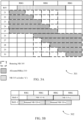
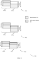
- FIGs. 3A and 3B illustrate examples of resource grids 301 and 302 that support retuning for flexible resource allocation in accordance with aspects of the present disclosure.
- resource grids 301 and 302 may be implemented by aspects of wireless communication systems 100 and/or 200.
- resource grid 301 illustrates various downlink resource allocations defined using RIV values 21 through 30 (e.g., with RIV values 0 to 20 not shown).
- the operating bandwidth is 10 MHz with 50 RBs, and an RBG size of 3 PRBs is defined.
- NB 315-a may be a NB of a wider system bandwidth, and may not be aligned with an RBG boundary.
- the UE may identify allocated RBs 310 based on an indication from the base station.
- the indication may include a grant, and may be received via DCI.
- the indication may include a RIV value, which may be used by the UE to determine a starting RB of the allocated RBs 310, as well as the number of RBs.
- the starting RB of allocated RBs 310 may be aligned with a RBG boundary.
- the resource allocation for the communication may be associated with NB 315-a with index 'k'.
- the resource allocation may be within a single narrowband, and the tuning band may be the same as the narrowband. In some other cases, the tuning band may be different from the narrowband.
- tuning NB 305 may start from the starting RB (i.e., as seen for RIV 21 to 25).
- the location of the tuning band for the resource allocation i.e., location within system bandwidth
- the UE may retune to the tuning band if at least a portion of the resource allocation is outside the predefined narrowband.
- the tuning band and the narrowband may be the same size (e.g., 6 consecutive PRBs).
- the tuning band may be the same as the narrowband (e.g., if the starting RB is not aligned with a RBG boundary). In some other cases, if an ending RB of the resource allocation is aligned with an RBG boundary above a predefined narrowband in the system bandwidth (i.e., if RB start + L CRBs - 1 is aligned with an RBG boundary, where L CRBs is associated with number of RBs for the resource allocation), the tuning NB 305 may end at the ending RB of the resource allocation (i.e., last RB of allocated RBs 310). Thus, as shown for RIV values 26 to 30, the tuning NB 305 may end at the RBG boundary, which may be outside the predefined narrowband. In some other cases, the tuning band may be the same as the narrowband (i.e., if the resource allocation is entirely within the narrowband), and the UE may determine not to retune.
- the UE may receive an indication of a narrowband shift from the network or base station (e.g., for PDSCH with CEModeB).
- the narrowband shift may be used to indicate a shift (e.g., in RBs) with respect to the narrowband (e.g., NB 315-b, and NB 315-c).
- the tuning narrowband may adjusted according to the shifted NB (i.e., NB 315-b and NB 315-c after applying the shift).
- the indicated shift may be used to align the starting RB of the resource allocation with a RBG boundary.
- the UE using a flexible starting PRB may retune NB 315-b and NB 315-c as the tuning NBs 320-b and 320-c (e.g., which may also be referred to as retuned NBs 320-b and 320-c) based on a ⁇ -1' RB shift.
- the tuning NBs 320-b and 320-c e.g., which may also be referred to as retuned NBs 320-b and 320-c
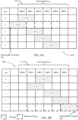
- FIGs. 4A and 4B illustrate examples of resource grids 401 and 402 that support retuning for flexible resource allocation in accordance with aspects of the present disclosure.
- resource grids 401 and 402 may be implemented by aspects of wireless communication system 100 and/or 200.
- resource grids 401 and 402 illustrate various uplink resource allocations for portions of 3/10/15 MHz, and 20 MHz bandwidth.
- the uplink allocations may be indicated by a wideband RIV of a UL RA type (e.g., UL RA type 0), and may be used to indicate a flexible starting PRB within the system bandwidth.
- a UL RA type e.g., UL RA type 0
- a portion of allocated resources 410 may be located outside a narrowband, such as NB 405.
- NB 405 may be an example of a narrowband of the system bandwidth, and may be predefined.
- a tuning NB may be determined based on a portion of the resource allocation being located outside a narrowband.
- the portion of the allocated resources outside a narrowband may include one or more left edge RBs 425 (e.g., left edge RBs 425-a or 425-b) that are not included in NB 405 of the system bandwidth.
- left edge RBs 425 e.g., left edge RBs 425-a or 425-b
- left edge RBs may be used to refer to edge RBs at the lower end of the system bandwidth
- right edge RBs may be used to refer to edge RBs at the upper end of the system bandwidth.
- the tuning NB e.g., retuned NB
- the tuning NB may be determined to start from a lowest RB (e.g., RB start 415-a, or RB start 415-b) of the system bandwidth.
- the portion of the resource allocation (e.g., allocated resources 410) outside NB 405 may include one or more right edge RBs 430 (e.g., right edge RBs 430-a or 430-b) that are not included in NB 405 of the system bandwidth.
- the tuning NB e.g., retuned NB
- the tuning NB may start from the starting RB of the resource allocation, as further described with reference to FIG. 5 . In some other cases, the tuning NB may end at an ending RB of the resource allocation.
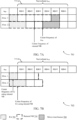
- FIG. 5 illustrates an example of a resource grid 500 that supports retuning for flexible resource allocation in accordance with aspects of the present disclosure.
- resource grid 500 may be implemented by aspects of wireless communication system 100 or 200. As shown, resource grid 500 illustrates various uplink resource allocations for portions of 3/10/15 MHz, and 20 MHz bandwidth.
- the UE may identify an uplink resource allocation (e.g., for PUSCH CEModeA), and determine that a portion of allocated resources 510 are not fully contained within a single NB 505 (e.g., NB 505-a or NB 505-b). In such cases, the UE may determine a starting RB (e.g., RB start 515-a) for the allocated resources 510, and the tuning NB (e.g., retuned NB) may include six (6) consecutive PRBs starting from the starting RB (e.g., RB start 515-a).
- the tuning NB e.g., retuned NB
- NB 505-c and NB 505-d may be separated by one or more RBs 520, and allocated resources 510 may include a starting RB (e.g., RB start 515-b).
- the UE may perform retuning, where the tuning NB (e.g., retuned NB) starts from the starting RB (e.g., RB start 515-b).
- FIGs. 6A and 6B illustrate examples of resource grids 601 and 602 that support retuning for flexible resource allocation in accordance with aspects of the present disclosure.
- resource grids 601 and 602 may be implemented by aspects of wireless communication system 100 and/or 200.
- resource grids 601 and 602 illustrate examples of uplink resource allocations for a wireless system supporting the use of a flexible starting PRB for a 2-PRB allocation (e.g., for PUSCH with CEModeB).
- the UE may receive one or more bits in higher layer signaling (e.g., RRC signaling) from the base station, the bits indicating a shift for the 2-PRB allocation.
- RRC signaling e.g., RRC signaling
- 2-PRB allocations of RIV '110' and '111' may be shifted by a higher layer configured n RB .
- a decreased number of bits e.g., 3 or less
- n RB may be used to indicate a shift (in number of RBs) for the resource allocation.
- the 2-PRB RA may lie within a NB 615 (e.g., NB 615-a, NB 615-b), which may be a narrowband of the system bandwidth.
- a tuning narrowband e.g., retuned NB 610 may be determined based on the indicated shift.
- the tuning narrowband (e.g., retuned NB 610) may be the same as NB 615-a, based in part on a starting RB or ending RB for the 2-PRB RA.
- the 2-PRB allocation of ' 110' may be shifted outside NB 615-a.
- the tuning narrowband e.g., retuned NB 610
- the tuning narrowband may start from n RB relative to the starting RB of NB 615-a.
- the tuning NB may be the same as the narrowband (not shown).
- tuning narrowband (e.g., retuned NB 610) may end at 'n RB + 3', since the resource allocation of '111' lies outside the NB 615-b.
- the tuning narrowband (e.g., retuned NB 610) may be the same as the narrowband (i.e., for resource allocation of ' 111' and a shift of '-1', '1', or '2').
- FIGs. 7A and 7B illustrate examples of resource grids 701 and 702 that support retuning for flexible resource allocation in accordance with aspects of the present disclosure.
- resource grids 701 and 702 may be implemented by aspects of wireless communication system 100 and/or 200.
- resource grids 701 and 702 illustrate examples of uplink resource allocations indicated by a wideband RIV of a UL RA type (e.g., for PUSCH with CEModeA), and/or the use of a flexible starting PRB for a 2-PRB allocation (e.g., for PUSCH with CEModeB), respectively.
- resource grid 701 may illustrate uplink resource allocations for portions of 3/10/15/20 MHz bandwidths.
- a portion of allocated resources, RA 705, may be located outside a narrowband, such as NB 715-a.
- NB 715-a may be an example of a narrowband of the system bandwidth, and may be predefined.
- a tuning NB may be determined based on a portion of the resource allocation being located outside a narrowband.
- the portion of the allocated resources (i.e., RA 705) outside a narrowband may include one or more left edge RBs that are not included in NB 715-a of the system bandwidth.
- left edge RBs may be used to refer to edge RBs at the lower end of the system bandwidth, while right edge RBs may be used to refer to edge RBs at the upper end of the system bandwidth.
- the tuning NB i.e., retuned NB 710
- the center frequency of retuned NB 710 may coincide with the center frequency of the communication utilizing RA 705.
- a center frequency used by a transmitter chain at the UE 115 for the subsequent communication coincides with the center of a newly defined retuning narrowband
- additional interference may be introduced at the receiver end.
- a UE 115 utilizing the newly defined retuning narrowband, retuned NB 710, for uplink communications may cause additional interference at the base station 105 (e.g., in the form of mirror image interference 720) for transmissions from one or more other UEs 115 utilizing a different narrowband.
- the center frequency of the subsequent communication may be adjusted to coincide with the center frequency of the resource allocation, RA 705.
- the UE 115 may map frequency domain symbols to subcarriers in generating a time-domain signal and modify a radio frequency used by a mixer to generate the signal around the center frequency with the center frequency coinciding with the center frequency of the resource allocation.
- Selection of the center frequency of the second communication may be based on a coverage enhancement mode for the UE (e.g., CEModeA or CEModeB), a tuning time capability of the UE, a tuning configuration received from the base station, a reference signal configuration for the subsequent communication utilizing the RA 705, or a combination thereof.
- a portion of allocated resources, RA 705, may be located outside a narrowband, such as NB 715-b.
- NB 715-a may be an example of a narrowband of the system bandwidth, and may be predefined.
- a UE in order to mitigate mirror image interference at the receiver end, may determine a center frequency of the communication utilizing the allocated resources to coincide with a center of the resource allocation.
- the UE may set the center frequency of the communication utilizing the allocated resources to coincide with the center of an allocation located narrowband (i.e., tuning NB) for PUSCH CEModeA, and to coincide with the center of the resource allocation for PUSCH CEModeB.
- tuning NB narrowband
- UEs that have requested zero (or negligible) tuning time may utilize a center of the resource allocation for setting the center frequency of the communication, irrespective of the coverage enhancement mode.
- the UE 115 may retune its transmitter chain between each TTI in which it has an allocation (e.g., an allocation outside a configured narrowband or in a shifted narrowband) to place the center frequency in the center of the allocation.
- the UE may receive a tuning configuration for setting the center frequency of the communication from the base station via a unicast or broadcast transmission (e.g., system information (SI)).
- SI system information
- the tuning configuration may be UE-specific, or may be cell-specific (e.g., applies to all UEs in the cell).
- the tuning configuration may be dependent on whether a sounding reference signal (SRS) transmission is configured (e.g., for the TTI prior to retuning).
- SRS sounding reference signal
- the UE may drop the SRS.
- the UE may receive a tuning configuration for setting the center frequency of the communication to coincide with the center of the resource allocation (e.g., instead of the center of the tuned narrowband). Additionally or alternatively, the tuning configuration may be dependent on the scheduled resource allocation.
- the UE may refrain from frequent retuning.
- the base station may configure the UE for setting the center frequency in the center of the resource allocation, Otherwise (e.g., where the resources are dynamically scheduled or the UE is configured for frequency hopping) the UE may be configured by the base station for setting the center frequency in the center of the tuning narrowband.
- the UE may retune its transceiver even if the tuning configuration is for setting the center frequency of the communication to coincide with the center of the scheduled RA. In some other cases, the UE may receive the tuning configuration from the base station for setting the center frequency of the communication to be the same as the center of the tuning band.
- FIG. 8 illustrates an example of a resource grid 800 that supports retuning for flexible resource allocation in accordance with aspects of the present disclosure.
- resource grid 800 may be implemented by aspects of wireless communication system 100, and illustrates examples of one or more puncturing and dropping rules utilized during retuning.
- carriers may transmit bidirectional communications using frequency division duplex (FDD) (e.g., using paired spectrum resources) or time division duplex (TDD) operation (e.g., using unpaired spectrum resources).
- FDD frequency division duplex
- TDD time division duplex
- Frame structures for FDD e.g., frame structure type 1
- TDD time division duplex
- each subframe may carry UL or DL traffic
- special subframes may be used to switch between DL and UL transmission.
- Allocation of UL and DL subframes within radio frames may be symmetric or asymmetric and may be statically determined or may be reconfigured semi-statically.
- Special subframes may carry DL or UL traffic and may include a Guard Period (GP) between DL and UL traffic.
- a special subframe may be composed of three distinct portions: a Downlink Pilot Time Slot (DwPTS), a guard period (GP), and an Uplink Pilot Time Slot (UpPTS), each of which may have a configurable length. It should be noted that the sum of the lengths may be equal to the length of a normal subframe.
- DwPTS Downlink Pilot Time Slot
- GP guard period
- UpPTS Uplink Pilot Time Slot
- control channel 810 may occupy a portion of subframes 805-a and 805-b, and may be an example of an uplink control channel (e.g., PUCCH), or a downlink control channel (e.g., PDCCH).
- MTC control channel 815 and shared channel 820 in subframe 805-a may represent a first resource allocation associated with NB 825.
- shared channel 820 may be an uplink shared channel (e.g., PUSCH), or a downlink shared channel(e.g., PDSCH).
- NB 825 may also be the associated tuning band for the first resource allocation.
- a UE may also identify a second resource allocation (e.g., shared channel 820) in subframe 805-b.
- the UE may determine that a tuning narrowband, for example, retuned NB 830 (i.e., tuning band associated with the second resource allocation) is different from the first tuning band. In such cases, the UE may determine to perform retuning from the first tuning band to the second tuning band.
- the UE may also puncture one or more symbols from the second communication to account for the retuning time. For instance, the UE may establish a guard period between the two consecutive communications in subframes 805-a and 805-b, based in part on the retuning time. As shown in FIG. 8 , one or more symbols may be punctured (i.e., punctured symbols 835) from control channel 810 in subframe 805-b. In some cases, one or two PDCCH symbols may be sufficient for retuning, and the UE may refrain from puncturing PDSCH or MPDCCH in the second subframe. In other cases, the UE may puncture one or more symbols from PDSCH or MPDCCH to account for the retuning time.
- the UE may transmit a combination of periodic SRS and UL DMRS for link adaptation and demodulation, respectively.
- DMRS may be contained at the beginning of a subframe and may be used by a base station for channel estimation, whereas the SRS may be deployed to assist a base station in estimating the uplink channel quality over a wider bandwidth.
- the base station may use this uplink channel quality information for uplink frequency selective scheduling.
- SRS may also be used for uplink timing estimation as part of timing alignment procedure between the base station and the UE.
- the UE may refrain from transmitting the SRS in the same PRBs where the PUSCH is transmitted, or even in the same subframe as the PUSCH (e.g., the UE may transmit the SRS in PRBs different from the PRBs where the PUSCH is transmitted, or in a subframe different from the subframe as the PUSCH).
- the SRS may be transmitted in a first subframe, and a PUSCH may be transmitted in the first subframe, and a subsequent, second subframe.
- the UE may be configured for SRS transmissions (e.g., periodic or aperiodic) via RRC signaling, DCI, or any other type of control signaling.
- the SRS may be transmitted in uplink subframes, which may also be referred to as normal subframes, as well as special subframes (e.g., including an uplink pilot time slot (UpPTS)).
- UpPTS uplink pilot time slot
- the UpPTS may primarily be utilized for SRS or RACH transmissions.
- the UE may not be configured for SRS transmissions in the UpPTS, however, one or more resources may be allocated for SRS transmission in a first subframe, and for PUSCH transmission in the first and a second subframe.
- the second subframe may be subsequent to the first subframe (e.g., the first subframe may be a subframe N, and the second subframe may be a subframe N+1).
- the tuning bands for PUSCH in the first and second subframes are different, the UE may proceed to drop SRS in the first normal subframe.
- the tuning bands for PUSCH in the first and second subframes may be the same, but SRS may still be dropped, for example, if at least a portion of the SRS is outside the tuning band.
- the UE may be configured for SRS transmissions in the UpPTS, and the SRS may be transmitted in an uplink (or normal) subframe.
- the UE may perform retuning from the first tuning band (e.g., a narrowband of the system bandwidth for carrying the SRS) to the retuning band.
- the UE may establish a guard period between the two consecutive uplink transmissions, which may be based in part on the retuning time.
- establishing the guard period may include puncturing one or more symbols of the second communication based on the retuning. As shown in FIG. 8 , one or more symbols may be punctured (i.e., punctured symbols 835) from control channel 810 in subframe 805-b.
- the SRS may be configured to be transmitted in the UpPTS of a subframe, such as a special subframe, while resources may be allocated for PUSCH transmission in a second subframe.
- the UE may refrain from transmitting the SRS (i.e., drop SRS) in the first subframe.
- the UE may perform retuning from the first tuning band (e.g., a narrowband of the system bandwidth for carrying the SRS) to the retuning band.
- the UE may establish a guard period between the two consecutive uplink transmissions, which may be based in part on the retuning time.
- the UE may identify a resource allocation for a downlink data transmission (e.g., PDSCH) in a DwPTS in a special subframe, and may identify another resource allocation for SRS transmission in UpPTS of the same special subframe.
- the two resource allocations may be associated with different tuning bands, and the UE may refrain from transmitting the SRS if a portion of the SRS is outside the first tuning band of PDSCH in DwPTS.
- the UE may be configured for SRS transmissions in the UpPTS, and may not drop SRS even if a portion of the SRS is outside the first tuning band. In such cases, the UE may establish a guard period, in addition to retuning from the first tuning band to the second tuning band (i.e., retuning band of SRS).
- FIG. 9 illustrates examples 900 of resource grids 901 through 903 that support retuning for flexible resource allocation in accordance with aspects of the present disclosure.
- resource grids 901 through 903 may be implemented by aspects of wireless communication systems 100 and/or 200.
- a UE may be configured to monitor a control channel within a narrowband. As illustrated in resource grid 901, the UE may be configured to monitor MTC control channel 925 occupying a portion of NB 915-a in subframe 905-a.
- a base station transmitting control information to a UE may configure search space sets according to control channel candidates (e.g., PDCCH candidates) to use for control channel transmissions.
- the base station may determine a control resource set (CORESET) containing the search space set.
- This CORESET may include a number of control channel elements (CCEs) and the search space set may be mapped to a CCE space corresponding to a subset of CCEs of the CORESET.
- the base station may identify control channel candidates to allocate at each aggregation level for the search space set, and may assign positions for the control channel candidates within the CCE space according to a hash function.
- the UEs may identify this search space set configuration, and may monitor the CCEs corresponding to the hashed control channel candidates for any DCI transmissions from the base station.
- the UE may be configured to monitor MTC control channel 925 and receive downlink transmissions over shared channel 910 concurrently (e.g., in the same subframe).
- a portion of the resource allocation for shared channel 910 in subframe 905-b may be outside NB 915-a (e.g., tuning NB 920-a may be shifted by 1 PRB, relative to NB 915-a).
- the tuning band associated with the resource allocation i.e., tuning NB 920-a
- the UE may refrain from monitoring MPDCCH if the tuning NB 920-a is different from NB 915-a.
- the UE may monitor a portion of the MTC control channel of NB 915-a that overlaps with the tuning NB 920-a. That is, the UE may monitor MPDCCH candidates that are included within the portion of the MTC control channel of NB 915-a that overlap with the tuning NB 920-a.
- a UE may be configured for NB 915-b in subframe 905-c, which may include a configured MTC control channel 925.
- a portion of the resource allocation for shared channel 910 in subframe 905-d may be outside NB 915-b (e.g., tuning NB 920-b may be shifted by 2 PRBs or 3 PRBs relative to NB 915-b).
- the tuning band associated with the resource allocation i.e., tuning NB 920-b
- subframe 905-c there may be no overlap between the MTC control channel 925 in subframe 905-c and the retuning band (e.g., tuning NB 920-b) for subframe 905-d.
- the UE may refrain from monitoring the MPDCCH in subframe 905-d (e.g., subframes where the tuned NB based on a NB shift does not overlap with the MPDCCH for a non-shifted NB).
- the UE may be configured to monitor a control channel within the tuning NB (e.g., shift the control channel from the control channel allocation in the non-shifted NB).
- the UE may be configured for NB 915-c (e.g., non-shifted NB) in subframe 905-e, which may include a configured MTC control channel 925.
- a portion of the resource allocation for shared channel 810 in subframe 905-f may be outside NB 915-c (e.g., tuning NB920-c may be shifted by 1 PRB, 2 PRBs or 3 PRBs relative to NB 915-b).
- the UE may monitor an adjusted MTC control channel 925 within the tuning NB 920-c for subframe 905-f.
- MTC control channel 925 may be adjusted based in part on a relative offset of the tuning NB 920-c to the first narrowband (e.g., NB 915-c).
- tuning NBs 920-a through 920-c may also be referred to as retuned NBs 920-a through 920-c.
- FIG. 10 shows an example flowchart 1000 that supports retuning for flexible resource allocation in accordance with aspects of the present disclosure.
- the flowchart 1000 may implement aspects of the wireless communications systems 100 and 200.
- the flowchart 1000 may be performed by a wireless device, such as a UE 115 or UE 115-a as described herein.
- the flowchart 1000 may illustrate a scheme that enables the wireless device to perform retuning for flexible resource allocation, supportive of frequency hopping or frequency diversity in transmissions, while maintaining reliable performance.
- the wireless device may receive downlink control information transmitted from a base station.
- the downlink control information may include a narrowband index (e.g., indicative of narrowband shifts) and resource indication values (e.g., indicative of resource allocations).
- the downlink control information may include a narrowband index for downlink resource allocations, without a narrowband index for uplink resource allocations.
- the downlink control information may indicate a first resource allocation, a second resource allocation, or both.
- the downlink control information may indicate a tuning configuration.
- the wireless device may identify a first resource allocation (e.g., first RA 210 a of FIG. 2 ) for a first communication in a first TTI (e.g., a subframe 'N') and a second resource allocation (e.g., second RA 210 b of FIG. 2 ) for a second communication in a second, subsequent TTI (e.g., a subframe 'N').
- the first resource allocation e.g., first RA 210 a of FIG. 2
- the UE may identify a set of resource blocks allocated for the first communication at subframe 'N' and identify a set of resource blocks allocated for the second communication at subframe ⁇ N+1' .
- a portion of the first resource allocation may be located outside the first narrowband, or a portion of the second resource allocation may be located outside the second narrowband.
- the first and second communications may be downlink or uplink communications.
- the wireless device may determine a first tuning band associated with the first resource allocation for the first TTI, and a second tuning band associated with the second resource allocation for the second TTI.
- the wireless device may determine the tuning bands (e.g., the second tuning band) based on resource allocations and resource block groups for a system bandwidth.
- the wireless device may determine resource block groups associated with resource blocks of the second resource allocation for the second TTI.
- the wireless device may define or determine the second tuning band based on an alignment between starting or ending resource blocks and a boundary of a resource block group, for example, as described in FIGs. 3A and 3B .
- the wireless device may determine the first tuning band is different from the second tuning band.
- the wireless device may retune from the first tuning band to the second tuning band.
- the wireless device may retune from the first tuning band to the second tuning band between the first communication (e.g., at subframe 'N') and the second communication (e.g., at subframe ⁇ N+1').
- the wireless device may determine whether to retune between the first communication and the second communication, based on whether a narrowband containing the resource allocation changes between the subframes (e.g., based on the second resource allocation). Accordingly, the UE may retune from using the resource blocks allocated for the first communication to using the resource blocks allocated for the second communication.
- the wireless device may set the center frequency associated with the second communication to coincide with a center of the second tuning band. In an example, the wireless device may set the center frequency associated with the second communication to coincide with a center of the second resource allocation (e.g., as described in FIG. 7B , where the center frequency of LTL using the retuned NB coincides with the center of the resource allocation, RA 705, at allocation 2). In some examples, the wireless device may retune between consecutive TTIs or subframes (e.g., subframes N and N+1 as described in FIG. 2 ). In an example, during retuning, the wireless device may refrain from communicating with the base station or other wireless devices.
- FIG. 11 shows a block diagram 1100 of a device 1105 that supports retuning for flexible resource allocation in accordance with aspects of the present disclosure.
- the device 1105 may be an example of aspects of a UE 115 as described herein.
- the device 1105 may include a receiver 1110, a communications manager 1115, and a transmitter 1120.
- the device 1105 may also include a processor. Each of these components may be in communication with one another (e.g., via one or more buses).
- the receiver 1110 may receive information such as packets, user data, or control information associated with various information channels (e.g., control channels, data channels, and information related to retuning for flexible resource allocation, etc.). Information may be passed on to other components of the device 1105.
- the receiver 1110 may be an example of aspects of the transceiver 1420 described with reference to FIG. 14 .
- the receiver 1110 may utilize a single antenna or a set of antennas.
- the communications manager 1115 may identify, at a UE, a first resource allocation for a first communication in a first TTI and a second resource allocation for a second communication in a second, subsequent TTI, where the first resource allocation is associated with a first narrowband and the second resource allocation is associated with a second narrowband, and where a portion of the first resource allocation is located outside the first narrowband or a portion of the second resource allocation is located outside the second narrowband, determine that a first tuning band associated with the first resource allocation for the first TTI is different from a second tuning band associated with the second resource allocation for the second TTI, and retune from the first tuning band to the second tuning band between the first communication and the second communication based on the determining.
- the communications manager 1115 may be an example of aspects of the communications manager 1410 described herein.
- the communications manager 1115 may be implemented in hardware, code (e.g., software or firmware) executed by a processor, or any combination thereof. If implemented in code executed by a processor, the functions of the communications manager 1115, or its sub-components may be executed by a general-purpose processor, a DSP, an application-specific integrated circuit (ASIC), a FPGA or other programmable logic device, discrete gate or transistor logic, discrete hardware components, or any combination thereof designed to perform the functions described in the present disclosure.
- code e.g., software or firmware
- ASIC application-specific integrated circuit
- FPGA field-programmable gate
- the communications manager 1115 may be physically located at various positions, including being distributed such that portions of functions are implemented at different physical locations by one or more physical components.
- the communications manager 1115, or its sub-components may be a separate and distinct component in accordance with various aspects of the present disclosure.
- the communications manager 1115, or its sub-components may be combined with one or more other hardware components, including but not limited to an input/output (I/O) component, a transceiver, a network server, another computing device, one or more other components described in the present disclosure, or a combination thereof in accordance with various aspects of the present disclosure.
- I/O input/output
- the transmitter 1120 may transmit signals generated by other components of the device 1105.
- the transmitter 1120 may be collocated with a receiver 1110 in a transceiver module.
- the transmitter 1120 may be an example of aspects of the transceiver 1420 described with reference to FIG. 14 .
- the transmitter 1120 may utilize a single antenna or a set of antennas.
- FIG. 12 shows a block diagram 1200 of a device 1205 that supports retuning for flexible resource allocation in accordance with aspects of the present disclosure.
- the device 1205 may be an example of aspects of a device 1105, or a UE 115 as described herein.
- the device 1205 may include a receiver 1210, a communications manager 1215, and a transmitter 1235.
- the device 1205 may also include a processor. Each of these components may be in communication with one another (e.g., via one or more buses).
- the receiver 1210 may receive information 1240 such as packets, user data, or control information associated with various information channels (e.g., control channels, data channels, and information related to retuning for flexible resource allocation, etc.).
- the information 1240 may include downlink control information transmitted from a base station 105.
- the downlink control information may indicate a first resource allocation (e.g., first RA 210 a of FIG. 2 ), a second resource allocation (e.g., a second RA 210 b of FIG. 2 ), or both.
- the downlink control information may indicate a tuning configuration.
- the information 1240 may be passed on to other components of the device 1205.
- the receiver 1210 may electrically send information received from another device (e.g., a base station 105), such as downlink control information (e.g., a narrowband index associated with downlink or uplink resource allocations, an RIV for a resource allocation), and the like, to the communications manager 1215.
- a base station 105 e.g., a base station 105
- downlink control information e.g., a narrowband index associated with downlink or uplink resource allocations, an RIV for a resource allocation
- the receiver 1210 may be an example of aspects of the transceiver 1420 described with reference to FIG. 14 .
- the receiver 1210 may utilize a single antenna or a set of antennas.
- the communications manager 1215 may be an example of aspects of the communications manager 1115 as described herein.
- the communications manager 1215 may include a RA component 1220, a tuning band component 1225, and a retuning component 1230.
- the communications manager 1215 may be an example of aspects of the communications manager 1410 described herein.
- the RA component 1220 may identify, at a UE, a first resource allocation for a first communication in a first TTI and a second resource allocation for a second communication in a second, subsequent TTI, where the first resource allocation is associated with a first narrowband and the second resource allocation is associated with a second narrowband, and where a portion of the first resource allocation is located outside the first narrowband or a portion of the second resource allocation is located outside the second narrowband.
- the RA component 1220 may receive, from the receiver 1210, resource allocation information 1245 indicating RIV values (e.g., indicative of resource allocations and resource blocks in the resource allocations), for example, RIVs 21 to 25 as described in FIG. 3A .
- the resource allocation information 1245 may include a set of bits indicative of the resource allocations and associated resource blocks.
- the RA component 1220 may determine starting resource blocks of a narrowband (e.g., the first and second narrowbands), the number of resource blocks in the resource allocations, and RBG boundaries associated with the narrowband, based on the RIV values indicated by the resource allocation information 1245, and may output allocation information 1255 indicating the resource allocations and resource blocks to the tuning band component 1225.
- the allocation information 1255 may include a set of bits indicating the resource allocations.
- the tuning band component 1225 may determine that a first tuning band associated with the first resource allocation for the first TTI is different from a second tuning band associated with the second resource allocation for the second TTI. For example, the tuning band component 1225 may receive the allocation information 1255 indicating the resource allocations, and may determine a center frequency of the second communication (e.g., an uplink communication) based on a coverage enhancement mode for the device 1205, a tuning time capability of the device 1205, the tuning configuration (e.g., received from the base station 105), a reference signal configuration for the second communication, or a combination thereof. The tuning band component 1225 may output frequency information 1260 to the retuning component 1230 indicating the center frequency of the second communication.
- a center frequency of the second communication e.g., an uplink communication
- the tuning band component 1225 may output frequency information 1260 to the retuning component 1230 indicating the center frequency of the second communication.
- the frequency information 1260 may include a set of bits indicating the center frequency and the associated resource allocation.
- the frequency information 1260 may indicate setting the center frequency associated with the second communication to coincide with a center of the second resource allocation (e.g., as described in FIG. 7B , where the center frequency of UL using the retuned NB coincides with the center of the resource allocation, RA 705, at allocation 2).
- the retuning component 1230 may retune from the first tuning band to the second tuning band between the first communication and the second communication based on the determining.
- the retuning component 1230 may receive, from the receiver 1210, a narrowband shift 1250.
- the narrowband shift 1250 may include a set of bits indicating the shift amount and the associated resource allocations.
- the retuning component 1230 may determine a starting RB and an ending RB of the second narrowband (e.g., as described in FIGS. 6A and 6B ) based on the narrowband shift 1250 and the frequency information 1260 (e.g., indicating the center frequency of the second communication).
- the retuning component 1230 may pass retuning information 1265 indicating retuning information to other components of the device 1205 for processing.
- the retuning information 1321 may include a set of bits indicating whether to retune from the first tuning band to the second tuning band.
- the retuning component 1230 may pass the retuning information 1265 (or other information based on the retuning information included in the retuning information 1265) to the transmitter 1235.
- the transmitter 1235 may transmit signals generated by other components of the device 1205.
- the transmitter 1235 may be collocated with a receiver 1210 in a transceiver module.
- the transmitter 1235 may be an example of aspects of the transceiver 1420 described with reference to FIG. 14 .
- the transmitter 1235 may utilize a single antenna or a set of antennas.
- the transmitter 1235 may receive retuning information 1265 (e.g., starting RB and an ending RB of the second narrowband) for transmission and may identify time-frequency resources over which the information is to be transmitted.
- the transmitter 1235 may modulate the information over the identified time-frequency resources in order to transmit the signal 1270.
- FIG. 13 shows a block diagram 1300 of a communications manager 1305 that supports retuning for flexible resource allocation in accordance with aspects of the present disclosure.
- the communications manager 1305 may be an example of aspects of a communications manager 1115, a communications manager 1215, or a communications manager 1410 described herein.
- the communications manager 1305 may include a RA component 1310, a tuning band component 1315, a retuning component 1320, a RB component 1325, a control channel component 1330, a shift component 1335, a SRS component 1340, and a guard period component 1345.
- Each of these modules may communicate, directly or indirectly, with one another (e.g., via one or more buses).
- the RA component 1310 may identify, at a UE, a first resource allocation (e.g., first RA 210 a of FIG. 2 ) for a first communication in a first TTI and a second resource allocation (e.g., second RA 210 b of FIG. 2 ) for a second communication in a second, subsequent TTI, where the first resource allocation is associated with a first narrowband (e.g., NB 215 of FIG. 2 ) and the second resource allocation is associated with a second narrowband (e.g., tuning NB 218 of FIG. 2 ), and where a portion of the first resource allocation is located outside the first narrowband or a portion of the second resource allocation is located outside the second narrowband.
- a first resource allocation e.g., first RA 210 a of FIG. 2
- a second resource allocation e.g., second RA 210 b of FIG. 2
- the RA component 1310 may receive resource allocation information 1333 from the control channel component 1330 indicating resource allocations and resource blocks in the resource allocations.
- the resource allocation information 1333 may include RIV values indicative of the resource allocations and the resource blocks in the resource allocations.
- the RA component 1310 may output allocation information 1312 to one or more of the SRS component 1340, the tuning band component 1315, and the RB component 1325, where the allocation information 1312 may indicate the first resource allocation for the first TTI and the second resource allocation for the second TTI.
- the allocation information 1312 may include a set of bits indicating the resource allocations.
- the tuning band component 1315 may determine that a first tuning band associated with the first resource allocation for the first TTI is different from a second tuning band associated with the second resource allocation for the second TTI. In some aspects, the tuning band component may receive the allocation information 1312 from the RA component 1310 indicating the first resource allocation for the first TTI and the second resource allocation for the second TTI.
- the tuning band component 1315 may determine the second tuning band based on the second resource allocation and a set of RBGs for the system bandwidth. In some aspects, the tuning band component 1315 may receive, in the allocation information 1312, an indication of starting or ending resource blocks of a narrowband (e.g., the first and second narrowbands), the number of resource blocks in the resource allocations, and RBG boundaries associated with the narrowband (e.g., based on the RIV values). In some aspects, the tuning band component 1315 may receive shift information 1337 from the shift component 1335 which may indicate a shift of the second resource allocation relative to the second narrowband. The shift information 1337 may include a set of bits indicating the shift amount and the associated resource allocation.
- the tuning band component 1315 may output tuning band comparison information 1316 to one or more of the SRS component 1340 or the retuning component 1320 indicating whether the first tuning band is different from the second tuning band.
- the tuning band comparison information 1316 may include a set of bits indicating whether the first tuning band is different from the second tuning band and an associated difference amount.
- the tuning band component 1315 may output the second resource allocation 1317 to the RB component 1325 (e.g., RBs included in the second resource allocation, starting and ending RBs).
- the resource allocation 1317 may include a set of bits indicating the second resource allocation and RBs associated with the second resource allocation.
- the RB component 1325 may also identify boundaries of RBGs of the set of RBGs.
- the tuning band component 1315 may output frequency information 1318 indicating the center frequency of the second communication.
- the tuning band component 1315 may output the frequency information 1318 to one or more of the retuning component 1320 or the transmitter 1235.
- the frequency information 1318 may indicate setting the center frequency associated with the second communication to coincide with a center of the second resource allocation.
- the frequency information 1318 may include a set of bits indicating the center frequency and the associated resource allocation.
- the tuning band component 1315 may determine the second tuning band to start from a lowest RB of the system bandwidth when the portion of the second resource allocation located outside the second narrowband includes one or more edge RBs at a lower end of the system bandwidth that are not included in a narrowband of the system bandwidth.
- the tuning band component 1315 may determine the second tuning band to end at a highest RB of the system bandwidth when the portion of the second resource allocation outside the second narrowband includes one or more edge RBs at an upper end of the system bandwidth that are not included in a narrowband of the system bandwidth.
- the tuning band component 1315 may determine the second tuning band to start from a lowest RB of the second resource allocation when the portion of the second resource allocation outside the second narrowband is exclusive of one or more edge RBs at a lower end or an upper end of the system bandwidth that are not included in a narrowband of the system bandwidth. In some examples, the tuning band component 1315 may determine the second tuning band to start at a starting RB of the second resource allocation, or end at an ending RB of the second resource allocation.
- the tuning band component 1315 may determine the second tuning band based on the shift.
- the first tuning band corresponds to the first narrowband.
- the second tuning band corresponds to the second narrowband.
- the second tuning band starts at a starting RB of the second resource allocation.
- the second tuning band ends at an ending RB of the second resource allocation.
- each of the first and second tuning bands are composed of continuous frequency resources having a same size as the first or the second narrowband.
- the first narrowband and the second narrowband correspond to a common narrowband.
- the first tuning band corresponds to the common narrowband.
- the first narrowband is different from the second narrowband.
- the tuning band component 1315 may determine a center frequency of the second communication based on a coverage enhancement mode for the UE, a tuning time capability of the UE, a tuning configuration received from a base station, a reference signal configuration for the second communication, or a combination thereof.
- the second communication may include an uplink communication.
- the coverage enhancement mode for the UE is one of a first coverage enhancement mode associated with a first amount of repetition (e.g., PUSCH CEModeA), or a second coverage enhancement mode associated with a second, larger amount of repetition (e.g., PUSCH CEModeB).
- determining the center frequency of the second communication includes setting the center frequency associated with the second communication to coincide with a center of the second tuning band, or setting the center frequency associated with the second communication to coincide with a center of the second resource allocation. In some aspects, setting the center frequency associated with the second communication may also be performed in conjunction with the retuning component 1320.
- the retuning component 1320 may retune from the first tuning band to the second tuning band between the first communication and the second communication based on the determining that a first tuning band associated with the first resource allocation for the first TTI is different from a second tuning band associated with the second resource allocation for the second TTI.
- the retuning component 1320 may receive resource block information 1326 from the RB component 1325 indicating one or more of the starting RB or the ending RB of the second tuning band.
- the resource block information 1326 may include a set of bits indicating positions of the RBs of the second tuning band.
- the retuning component 1320 may receive the tuning band comparison information 1316 from the tuning band component 1315 indicating whether the first tuning band is different from the second tuning band. In some aspects, the retuning component 1320 may receive the frequency information 1318 from the tuning band component 1315 indicating the center frequency of the second communication. In an example, the retuning component 1320 may output retuning information 1321 indicating the retuning from the first tuning band to the second tuning band between the first communication and the second communication. The retuning information 1321 may include a set of bits indicating whether to retune from the first tuning band to the second tuning band. In some aspects, the retuning component 1320 may output the retuning information 1321 to the guard period component 1345 or to the transmitter 1235.
- the RB component 1325 may determine a starting RB of the second tuning band based on an alignment of a starting RB of the second resource allocation with a boundary of an RBG of the set of RBGs.
- the RB component 1325 may receive the allocation information 1312 from the RA component indicating the first resource allocation for the first TTI and the second resource allocation for the second TTI.
- the RB component 1325 may receive the second resource allocation 1317 from the tuning band component 1315 indicating the second resource allocation (and RBs included in the second resource allocations) and boundaries of RBGs of the set of RBGs.
- the RB component 1325 may determine an ending RB of the second tuning band based on an alignment of an ending RB of the second resource allocation with a boundary of an RBG of the set of RBGs.
- the RB component 1325 may output resource block information 1326 to the retuning component 1320 indicating one or more of the starting RB or the ending RB of the second tuning band.
- the control channel component 1330 may receive, from a base station (e.g., via the receiver 1210), information 1331 such as packets, user data, or control information associated with various information channels (e.g., control channels, data channels, and information related to retuning for flexible resource allocation, etc.).
- information 1331 may include control information indicating the first resource allocation, the second resource allocation, or both.
- the control channel component 1330 may receive, from a base station, a tuning configuration in a unicast or broadcast transmission (e.g., using SI). The tuning configuration may be included in the information 1331.
- identifying the second resource allocation includes receiving control information in a TTI prior to the second TTI, the control information including a grant for the second resource allocation.
- control channel component 1330 may refrain from monitoring the control channel in the second TTI based on determining that at least a portion of the control channel does not overlap with the second tuning band.
- control channel component 1330 may identify a portion of the control channel within the first narrowband that overlaps in frequency with the second tuning band.
- control channel component 1330 may monitor, in the second TTI, the portion of the control channel for control information.
- control channel component 1330 may monitor an adjusted control channel in the second TTI for control information, the adjusted control channel being adjusted based on a relative offset of the second tuning band to the first narrowband.
- the UE is configured for monitoring a control channel within the first narrowband.
- control channel component 1330 may output narrowband information 1332 to the shift component 1336 indicating aspects of the first or second narrowband (e.g., a shift of the second narrowband with respect to the first narrowband).
- the narrowband information 1332 may include a set of bits indicating the shift of the second narrowband with respect to the first narrowband.
- control channel component 1330 may output resource allocation information 1333 to the RA component 1310 indicating resource allocations and resource blocks in the resource allocations.
- the resource allocation information 1333 may include RIV values 1245 indicative of the resource allocations and the resource blocks in the resource allocations.
- the resource allocation information 1333 may include a set of bits indicative of the resource allocations and associated resource blocks.
- the shift component 1335 may receive one or more bits indicating a shift of the second narrowband. In some examples, the shift component 1335 may receive one or more bits indicating a shift of the second resource allocation relative to the second narrowband. For example, the shift component 1335 may receive narrowband information 1332 indicating aspects of the second narrowband and allocation information 1311 indicating resource allocations and resource blocks associated with the resource allocations. In some examples, the shift component 1335 may pass information (e.g., shift information 1337) indicative of the shift in the resource allocation relative to the second narrowband to the tuning band component 1315.
- information 1332 indicating aspects of the second narrowband and allocation information 1311 indicating resource allocations and resource blocks associated with the resource allocations.
- the shift component 1335 may pass information (e.g., shift information 1337) indicative of the shift in the resource allocation relative to the second narrowband to the tuning band component 1315.
- the SRS component 1340 may identify a configuration for transmitting a SRS in the first TTI.
- the SRS component 1340 may receive tuning band comparison information 1316 from the tuning band component 1315 indicating whether the first tuning band is different from the second tuning band.
- the SRS component 1340 may output SRS transmission information 1341 (e.g., to the transmitter 1235) indicating whether to transmit the SRS or refrain from transmitting the SRS.
- the SRS transmission information 1341 may include an indication of a configuration for transmitting the SRS in the first TTI.
- the SRS transmission information 1341 may include a set of bits indicating whether to transmit the SRS and configurations for transmitting the SRS.
- the SRS component 1340 may refrain from transmitting the SRS based on determining the first tuning band is different from the second tuning band.
- the SRS component 1340 may identify, from the tuning band component 1315 or the guard period component 1345, a configuration for transmitting a SRS in the first TTI, where a portion of the SRS is outside the second tuning band.
- the SRS component 1340 may refrain from transmitting the SRS based on identifying that the portion of the SRS is outside the second tuning band.
- the SRS component 1340 may identify a configuration for a SRS in the first TTI, where a portion of the SRS is outside the second tuning band.
- the SRS component 1340 may receive guard information 1346 output by the guard period component 1345 indicating a guard period established between the first communication in the first TTI and the second communication in the second TTI. In some aspects, the SRS component 1340 may transmit the SRS (e.g., the SRS transmission information 1341 indicating a configuration for transmitting a SRS) based on the established guard period.
- the SRS component 1340 may transmit the SRS (e.g., the SRS transmission information 1341 indicating a configuration for transmitting a SRS) based on the established guard period.
- the guard period component 1345 may establish a guard period between the first communication in the first TTI and the second communication in the second TTI.
- the guard period component 1345 may output guard information 1346 indicating a guard period between the first communication in the first TTI and the second communication in the second TTI.
- the guard period component 1345 may output the guard information 1346 to the SRS component 1340.
- the guard information 1346 may include a set of bits indicating the duration of the guard period.
- the guard period component 1345 may puncture one or more symbols of the second communication based on the retuning. For example, the guard period component 1345 may puncture one or more symbols of the second communication based on the retuning information 1321 received from the retuning component 1320, which may indicate the retuning from the first tuning band to the second tuning band between the first communication and the second communication.
- the puncturing is based on determining that the first and second communications are downlink communications.
- the puncturing is based on determining that the first communication is an uplink communication and the second communication is a downlink communication
- FIG. 14 shows a diagram of a system 1400 including a device 1405 that supports retuning for flexible resource allocation in accordance with aspects of the present disclosure.
- the device 1405 may be an example of or include the components of device 1105, device 1205, or a UE 115 as described herein.
- the device 1405 may include components for bidirectional voice and data communications including components for transmitting and receiving communications, including a communications manager 1410, an I/O controller 1415, a transceiver 1420, an antenna 1425, memory 1430, and a processor 1440. These components may be in electronic communication via one or more buses (e.g., bus 1445).
- buses e.g., bus 1445
- the communications manager 1410 may identify, at a UE, a first resource allocation for a first communication in a first TTI and a second resource allocation for a second communication in a second, subsequent TTI, where the first resource allocation is associated with a first narrowband and the second resource allocation is associated with a second narrowband, and where a portion of the first resource allocation is located outside the first narrowband or a portion of the second resource allocation is located outside the second narrowband, determine that a first tuning band associated with the first resource allocation for the first TTI is different from a second tuning band associated with the second resource allocation for the second TTI, and retune from the first tuning band to the second tuning band between the first communication and the second communication based on the determining.
- the I/O controller 1415 may manage input and output signals for the device 1405.
- the I/O controller 1415 may also manage peripherals not integrated into the device 1405.
- the I/O controller 1415 may represent a physical connection or port to an external peripheral.
- the I/O controller 1415 may utilize an operating system such as iOS ® , ANDROID ® , MS-DOS ® , MS-WINDOWS ® , OS/2 ® , UNIX ® , LINUX ® , or another known operating system.
- the I/O controller 1415 may represent or interact with a modem, a keyboard, a mouse, a touchscreen, or a similar device.
- the I/O controller 1415 may be implemented as part of a processor.
- a user may interact with the device 1405 via the I/O controller 1415 or via hardware components controlled by the I/O controller 1415.
- the transceiver 1420 may communicate bi-directionally, via one or more antennas, wired, or wireless links as described herein.
- the transceiver 1420 may represent a wireless transceiver and may communicate bi-directionally with another wireless transceiver.
- the transceiver 1420 may also include a modem to modulate the packets and provide the modulated packets to the antennas for transmission, and to demodulate packets received from the antennas.
- the wireless device may include a single antenna 1425. However, in some cases the device may have more than one antenna 1425, which may be capable of concurrently transmitting or receiving multiple wireless transmissions.
- the memory 1430 may include RAM and ROM.
- the memory 1430 may store computer-readable, computer-executable code 1435 including instructions that, when executed, cause the processor to perform various functions described herein.
- the memory 1430 may contain, among other things, a BIOS which may control basic hardware or software operation such as the interaction with peripheral components or devices.
- the processor 1440 may include an intelligent hardware device, (e.g., a general-purpose processor, a DSP, a CPU, a microcontroller, an ASIC, an FPGA, a programmable logic device, a discrete gate or transistor logic component, a discrete hardware component, or any combination thereof).
- the processor 1440 may be configured to operate a memory array using a memory controller.
- a memory controller may be integrated into the processor 1440.
- the processor 1440 may be configured to execute computer-readable instructions stored in a memory (e.g., the memory 1430) to cause the device 1405 to perform various functions (e.g., functions or tasks supporting retuning for flexible resource allocation).
- the code 1435 may include instructions to implement aspects of the present disclosure, including instructions to support wireless communications.
- the code 1435 may be stored in a non-transitory computer-readable medium such as system memory or other type of memory. In some cases, the code 1435 may not be directly executable by the processor 1440 but may cause a computer (e.g., when compiled and executed) to perform functions described herein.
- FIG. 15 shows a flowchart illustrating a method 1500 that supports retuning for flexible resource allocation in accordance with aspects of the present disclosure.
- the operations of method 1500 may be implemented by a UE 115 or its components as described herein.
- the operations of method 1500 may be performed by a communications manager as described with reference to FIGs. 11 through 14 .
- a UE may execute a set of instructions to control the functional elements of the UE to perform the functions described herein.
- a UE may perform aspects of the functions described herein using special-purpose hardware.
- the UE may identify a first resource allocation for a first communication and a second resource allocation for a second communication.
- the UE may identify a first resource allocation for a first communication in a first TTI (e.g., a subframe 'N') and a second resource allocation for a second communication in a second, subsequent TTI (e.g., a subframe ⁇ N+1').
- the first resource allocation may be associated with the first narrowband
- the second resource allocation may be associated with the second narrowband.
- a portion of the first resource allocation may be located outside the first narrowband or a portion of the second resource allocation may be located outside the second narrowband.
- the UE may identify a set of resource blocks allocated for the first communication at subframe 'N' and identify a set of resource blocks allocated for the second communication at subframe 'N+1'.
- the operations of 1505 may be performed according to the methods described herein. In some examples, aspects of the operations of 1505 may be performed by a RA component as described with reference to FIGs. 11 through 14 .
- the UE may determine that a first tuning band associated with the first resource allocation (e.g., for the first TTI) is different from a second tuning band associated with the second resource allocation (e.g., for the second TTI). For example, the UE may determine whether the set of resource blocks allocated for the first communication at subframe 'N' differ from the set of resource blocks allocated for the second communication at subframe 'N+1'.
- the UE may determine the second tuning band based on the second resource allocation and a set of RBGs for the system bandwidth. For example, if the UE determines that one of the resource blocks allocated for the second communication (e.g., a portion of the second resource allocation) is outside the second narrowband, the UE may newly define a tuning band (e.g., the second tuning band) for retuning. For example, the UE may newly define a the tuning band (e.g., the second tuning band) for the second resource allocation, where the second tuning band is within the second narrowband.
- a tuning band e.g., the second tuning band
- the UE may define or determine the second tuning band based on RBGs for the system bandwidth and associated with the second resource allocation. For example, the UE may determine RBGs associated with the resource blocks of the second resource allocation. Accordingly, the UE may define or determine the second tuning band based on an alignment between resource blocks (e.g., a starting resource block, an ending resource block) of the second resource allocation and boundaries of the RBGs.
- the operations of 1510 may be performed according to the methods described herein. In some examples, aspects of the operations of 1510 may be performed by a tuning band component as described with reference to FIGs. 11 through 14 .
- the UE may retune from the first tuning band to the second tuning band.
- the UE may retune from the first tuning band to the second tuning band between the first communication and the second communication, based on determining that the first tuning band is different from the second tuning band.
- the UE may determine whether to retune between a communication in subframe 'N' and a communication in subframe ⁇ N+1' based on whether a narrowband containing the resource allocation changes between the subframes. For example, the UE may retune from the first tuning band to the second tuning band between the first communication at subframe 'N' and the second communication at subframe 'N'. Accordingly, the UE may retune so as to switch from using the resource blocks allocated for the first communication to using the resource blocks allocated for the second communication (e.g., the resource blocks of the newly defined tuning band, that is, the second tuning band).
- the operations of 1515 may be performed according to the methods described herein. In some examples, aspects of the operations of 1515 may be performed by a retuning component as described with reference to FIGs. 11 through 14 .
- CDMA code division multiple access
- TDMA time division multiple access
- FDMA frequency division multiple access
- OFDMA orthogonal frequency division multiple access
- SC-FDMA single carrier frequency division multiple access
- a CDMA system may implement a radio technology such as CDMA2000, Universal Terrestrial Radio Access (UTRA), etc.
- CDMA2000 covers IS-2000, IS-95, and IS-856 standards.
- IS-2000 Releases may be commonly referred to as CDMA2000 1X, 1X, etc.
- IS-856 TIA-856) is commonly referred to as CDMA2000 1xEV-DO, High Rate Packet Data (HRPD), etc.
- UTRA includes Wideband CDMA (WCDMA) and other variants of CDMA.
- a TDMA system may implement a radio technology such as Global System for Mobile Communications (GSM).
- GSM Global System for Mobile Communications
- An OFDMA system may implement a radio technology such as Ultra Mobile Broadband (UMB), Evolved UTRA (E-UTRA), Institute of Electrical and Electronics Engineers (IEEE) 802.11 (Wi-Fi), IEEE 802.16 (WiMAX), IEEE 802.20, Flash-OFDM, etc.
- UMB Ultra Mobile Broadband
- E-UTRA Evolved UTRA
- IEEE Institute of Electrical and Electronics Engineers
- Wi-Fi Wi-Fi
- WiMAX IEEE 802.16
- IEEE 802.20 Flash-OFDM
- UTRA and E-UTRA are part of Universal Mobile Telecommunications System (UMTS).
- LTE, LTE-A, and LTE-A Pro are releases of UMTS that use E-UTRA.
- UTRA, E-UTRA, UMTS, LTE, LTE-A, LTE-A Pro, NR, and GSM are described in documents from the organization named "3rd Generation Partnership Project" (3GPP).
- CDMA2000 and UMB are described in documents from an organization named "3rd Generation Partnership Project 2" (3GPP2).
- 3GPP2 3rd Generation Partnership Project 2
- the techniques described herein may be used for the systems and radio technologies mentioned herein as well as other systems and radio technologies. While aspects of an LTE, LTE-A, LTE-A Pro, or NR system may be described for purposes of example, and LTE, LTE-A, LTE-A Pro, or NR terminology may be used in much of the description, the techniques described herein are applicable beyond LTE, LTE-A, LTE-A Pro, or NR applications.
- a macro cell generally covers a relatively large geographic area (e.g., several kilometers in radius) and may allow unrestricted access by UEs 115 with service subscriptions with the network provider.
- a small cell may be associated with a lower-powered base station 105, as compared with a macro cell, and a small cell may operate in the same or different (e.g., licensed, unlicensed, etc.) frequency bands as macro cells.
- Small cells may include pico cells, femto cells, and micro cells according to various examples.
- a pico cell for example, may cover a small geographic area and may allow unrestricted access by UEs 115 with service subscriptions with the network provider.
- a femto cell may also cover a small geographic area (e.g., a home) and may provide restricted access by UEs 115 having an association with the femto cell (e.g., UEs 115 in a closed subscriber group (CSG), UEs 115 for users in the home, and the like).
- An eNB for a macro cell may be referred to as a macro eNB.
- An eNB for a small cell may be referred to as a small cell eNB, a pico eNB, a femto eNB, or a home eNB.
- An eNB may support one or multiple (e.g., two, three, four, and the like) cells, and may also support communications using one or multiple component carriers.
- the wireless communications system 100 or systems described herein may support synchronous or asynchronous operation.
- the base stations 105 may have similar frame timing, and transmissions from different base stations 105 may be approximately aligned in time.
- the base stations 105 may have different frame timing, and transmissions from different base stations 105 may not be aligned in time.
- the techniques described herein may be used for either synchronous or asynchronous operations.
- Information and signals described herein may be represented using any of a variety of different technologies and techniques.
- data, instructions, commands, information, signals, bits, symbols, and chips that may be referenced throughout the description may be represented by voltages, currents, electromagnetic waves, magnetic fields or particles, optical fields or particles, or any combination thereof.
- DSP digital signal processor
- ASIC application-specific integrated circuit
- FPGA field-programmable gate array
- PLD programmable logic device
- a general-purpose processor may be a microprocessor, but in the alternative, the processor may be any conventional processor, controller, microcontroller, or state machine.
- a processor may also be implemented as a combination of computing devices (e.g., a combination of a DSP and a microprocessor, multiple microprocessors, one or more microprocessors in conjunction with a DSP core, or any other such configuration).
- the functions described herein may be implemented in hardware, software executed by a processor, firmware, or any combination thereof. If implemented in software executed by a processor, the functions may be stored on or transmitted over as one or more instructions or code on a computer-readable medium. Other examples and implementations are within the scope of the disclosure and appended claims. For example, due to the nature of software, functions described herein can be implemented using software executed by a processor, hardware, firmware, hardwiring, or combinations of any of these. Features implementing functions may also be physically located at various positions, including being distributed such that portions of functions are implemented at different physical locations.
- Computer-readable media includes both non-transitory computer storage media and communication media including any medium that facilitates transfer of a computer program from one place to another.
- a non-transitory storage medium may be any available medium that can be accessed by a general purpose or special purpose computer.
- non-transitory computer-readable media may include random-access memory (RAM), read-only memory (ROM), electrically erasable programmable read only memory (EEPROM), flash memory, compact disk (CD) ROM or other optical disk storage, magnetic disk storage or other magnetic storage devices, or any other non-transitory medium that can be used to carry or store desired program code means in the form of instructions or data structures and that can be accessed by a general-purpose or special-purpose computer, or a general-purpose or special-purpose processor.
- RAM random-access memory
- ROM read-only memory
- EEPROM electrically erasable programmable read only memory
- CD compact disk
- magnetic disk storage or other magnetic storage devices or any other non-transitory medium that can be used to carry
- any connection is properly termed a computer-readable medium.
- the software is transmitted from a website, server, or other remote source using a coaxial cable, fiber optic cable, twisted pair, digital subscriber line (DSL), or wireless technologies such as infrared, radio, and microwave
- the coaxial cable, fiber optic cable, twisted pair, DSL, or wireless technologies such as infrared, radio, and microwave are included in the definition of medium.
- Disk and disc include CD, laser disc, optical disc, digital versatile disc (DVD), floppy disk and Blu-ray disc where disks usually reproduce data magnetically, while discs reproduce data optically with lasers. Combinations of the above are also included within the scope of computer-readable media.
Landscapes
- Engineering & Computer Science (AREA)
- Signal Processing (AREA)
- Computer Networks & Wireless Communication (AREA)
- Power Engineering (AREA)
- Mobile Radio Communication Systems (AREA)
Claims (15)
- Verfahren (1000, 1500) zur drahtlosen Kommunikation durch ein Benutzergerät, UE, umfassend:Identifizieren (1010, 1505), am UE, einer ersten Ressourcenzuweisung für eine erste Kommunikation in einem ersten Übertragungszeitintervall, TTI, und einer zweiten Ressourcenzuweisung für eine zweite Kommunikation in einem zweiten, nachfolgenden TTI, wobei die erste Ressourcenzuweisung mit einem ersten Schmalband assoziiert ist, umfassend einen ersten Satz von Ressourcenblöcken, RBs, und die zweite Ressourcenzuweisung mit einem zweiten Schmalband assoziiert ist, umfassend einen zweiten Satz von RBs, und wobei sich mindestens ein Ressourcenblock, RB, der ersten Ressourcenzuweisung außerhalb des ersten Satzes von RBs befindet oder sich mindestens ein RB der zweiten Ressourcenzuweisung außerhalb des zweiten Satzes von RBs befindet;Bestimmen (1015, 1510) eines zweiten Abstimmbands zumindest teilweise basierend auf der zweiten Ressourcenzuweisung und einem Satz von Ressourcenblockgruppen, RBGs, für eine Systembandbreite, wobei ein Start-RB des zweiten Abstimmbands zumindest teilweise auf einer Ausrichtung eines Start-RB der zweiten Ressourcenzuweisung mit einer Grenze eines RBG des Satzes von RBGs basiert; undNeuabstimmen (1020, 1515) von einem ersten Abstimmband auf das zweite Abstimmband zwischen der ersten Kommunikation und der zweiten Kommunikation zumindest teilweise basierend auf dem Bestimmen, dass sich das erste Abstimmband, das mit der ersten Ressourcenzuweisung für das erste TTI assoziiert ist, von dem zweiten Abstimmband, das mit der zweiten Ressourcenzuweisung für das zweite TTI assoziiert ist, unterscheidet.
- Verfahren (1000, 1500) nach Anspruch 1, ferner umfassend:
Bestimmen eines End-RB des zweiten Abstimmbands zumindest teilweise basierend auf einer Ausrichtung eines End-RB der zweiten Ressourcenzuweisung mit der Grenze des RBG des Satzes von RBGs. - Verfahren (1000, 1500) nach Anspruch 1, wobei die zweite Kommunikation eine Uplink-Kommunikation umfasst, wobei das Verfahren ferner umfasst:
Bestimmen einer Mittenfrequenz der zweiten Kommunikation zumindest teilweise basierend auf einem Abdeckungsverbesserungsmodus für das UE, einer Abstimmzeitfähigkeit des UE, einer von einer Basisstation empfangenen Abstimmkonfiguration, einer Referenzsignalkonfiguration für die zweite Kommunikation oder einer Kombination davon; und/oderwobei das Bestimmen der Mittenfrequenz der zweiten Kommunikation umfasst:
Einstellen der Mittenfrequenz, die der zweiten Kommunikation zugeordnet ist, so dass sie mit einer Mitte des zweiten Abstimmbands zusammenfällt; und/oderEinstellen der Mittenfrequenz, die der zweiten Kommunikation zugeordnet ist, so dass sie mit einer Mitte der zweiten Ressourcenzuweisung zusammenfällt; und/oderwobei die Abstimmkonfiguration von der Basisstation in einer Unicast-Übertragung oder einer Broadcast-Übertragung empfangen wird; und/oderwobei der Abdeckungsverbesserungsmodus für das UE einer von einem ersten Abdeckungsverbesserungsmodus, der einer ersten Wiederholungsmenge zugeordnet ist, oder einem zweiten Abdeckungsverbesserungsmodus, der einer zweiten, größeren Wiederholungsmenge zugeordnet ist, ist. - Verfahren (1000, 1500) nach Anspruch 1, wobei das UE zum Überwachen eines Steuerkanals innerhalb des ersten Schmalbands konfiguriert ist; und/oderferner umfassend:Identifizieren eines Abschnitts des Steuerkanals innerhalb des ersten Schmalbands, der sich in der Frequenz mit dem zweiten Abstimmband überlappt; undÜberwachen, im zweiten TTI, des Abschnitts des Steuerkanals auf eine Steuerinformation; und/oderferner umfassend:
Überwachen eines angepassten Steuerkanals im zweiten TTI auf eine Steuerinformation, wobei der angepasste Steuerkanal zumindest teilweise basierend auf einem relativen Versatz des zweiten Abstimmbands zum ersten Schmalband angepasst wird; und/oderferner umfassend:
Unterlassen des Überwachens des Steuerkanals im zweiten TTI zumindest teilweise basierend auf dem Bestimmen, dass sich zumindest ein Abschnitt des Steuerkanals nicht mit dem zweiten Abstimmband überlappt. - Verfahren (1000, 1500) nach Anspruch 1, ferner umfassend:Empfangen eines oder mehrerer Bits, die eine Verschiebung des zweiten Schmalbands angeben; undBestimmen des zweiten Abstimmbands zumindest teilweise basierend auf der Verschiebung; und/oderferner umfassend:Empfangen eines oder mehrerer Bits, die eine Verschiebung der zweiten Ressourcenzuweisung relativ zum zweiten Schmalband angeben; undBestimmen des zweiten Abstimmbands zumindest teilweise basierend auf der Verschiebung; und/oderwobei das zweite Abstimmband an einem Start-RB der zweiten Ressourcenzuweisung beginnt; und/oderwobei das zweite Abstimmband an einem End-RB der zweiten Ressourcenzuweisung endet.
- Verfahren (1000, 1500) nach Anspruch 1, wobei das Bestimmen des zweiten Abstimmbands umfasst:Bestimmen des zweiten Abstimmbands, um von einem niedrigsten RB der Systembandbreite zu beginnen, wenn der mindestens eine RB der zweiten Ressourcenzuweisung, der sich außerhalb des zweiten Schmalbands befindet, einen oder mehrere Rand-RBs an einem unteren Ende der Systembandbreite beinhaltet, die nicht in einem Schmalband der Systembandbreite beinhaltet sind; und/oderBestimmen des zweiten Abstimmbands, um an einem höchsten RB der Systembandbreite zu enden, wenn der mindestens eine RB der zweiten Ressourcenzuweisung außerhalb des zweiten Schmalbands einen oder mehrere Rand-RBs an einem oberen Ende der Systembandbreite beinhaltet, die nicht in einem Schmalband der Systembandbreite beinhaltet sind; und/oderBestimmen des zweiten Abstimmbands, um von einem Start-RB der zweiten Ressourcenzuweisung zu beginnen oder an einem End-RB der zweiten Ressourcenzuweisung zu enden.
- Verfahren (1000, 1500) nach Anspruch 1, ferner umfassend:
Empfangen, von einer Basisstation, einer Steuerinformation, die die erste Ressourcenzuweisung, die zweite Ressourcenzuweisung oder beides angibt. - Verfahren (1000, 1500) nach Anspruch 1, wobei das erste Abstimmband dem ersten Schmalband entspricht; und/oderwobei das zweite Abstimmband dem zweiten Schmalband entspricht; und/oderwobei das Identifizieren der zweiten Ressourcenzuweisung das Empfangen einer Steuerinformation in einem TTI vor dem zweiten TTI umfasst, wobei die Steuerinformation eine Genehmigung für die zweite Ressourcenzuweisung umfasst.
- Verfahren (1000, 1500) nach Anspruch 1, wobei jedes des ersten und des zweiten Abstimmbands aus kontinuierlichen Frequenzressourcen besteht, die eine gleiche Größe wie das erste oder das zweite Schmalband aufweisen; und/oder
wobei sich das erste Schmalband vom zweiten Schmalband unterscheidet. - Verfahren (1000, 1500) nach Anspruch 1, ferner umfassend:Identifizieren einer Konfiguration zum Übertragen eines Sondierungsreferenzsignals (SRS) in dem ersten TTI; undUnterlassen des Übertragens des SRS zumindest teilweise basierend auf dem Bestimmen, dass sich das erste Abstimmband vom zweiten Abstimmband unterscheidet; und/oderferner umfassend:Identifizieren einer Konfiguration zum Übertragen eines Sondierungsreferenzsignals, SRS, in dem ersten TTI, wobei ein Abschnitt des SRS außerhalb des zweiten Abstimmbands liegt; undUnterlassen des Übertragens des SRS zumindest teilweise basierend auf dem Identifizieren, dass der Abschnitt des SRS außerhalb des zweiten Abstimmbands liegt.
- Verfahren (1000, 1500) nach Anspruch 1, ferner umfassend:Identifizieren einer Konfiguration für ein Sondierungsreferenzsignal, SRS, in dem ersten TTI, wobei ein Abschnitt des SRS außerhalb des zweiten Abstimmbands liegt;Einrichten einer Schutzperiode zwischen der ersten Kommunikation in dem ersten TTI und der zweiten Kommunikation in dem zweiten TTI; undÜbertragen des SRS zumindest teilweise basierend auf dem Einrichten.
- Verfahren (1000, 1500) nach Anspruch 1, ferner umfassend:
Einrichten einer Schutzperiode zwischen der ersten Kommunikation in dem ersten TTI und der zweiten Kommunikation in dem zweiten TTI; undwobei das Einrichten der Schutzperiode umfasst:
Punktieren eines oder mehrerer Symbole der zweiten Kommunikation zumindest teilweise basierend auf dem Neuabstimmen; undwobei das Punktieren zumindest teilweise auf dem Bestimmen basiert, dass die erste und die zweite Kommunikation Downlink-Kommunikationen sind; undwobei das Punktieren zumindest teilweise auf dem Bestimmen basiert, dass die erste Kommunikation eine Uplink-Kommunikation ist und die zweite Kommunikation eine Downlink-Kommunikation ist. - Vorrichtung (1105, 1205, 1405) zur drahtlosen Kommunikation, umfassend:Mittel zum Identifizieren (1115, 1215, 1410), an der Vorrichtung (1105, 1205, 1405), einer ersten Ressourcenzuweisung für eine erste Kommunikation in einem ersten Übertragungszeitintervall, TTI, und einer zweiten Ressourcenzuweisung für eine zweite Kommunikation in einem zweiten, nachfolgenden TTI, wobei die erste Ressourcenzuweisung mit einem ersten Schmalband assoziiert ist, umfassend einen ersten Satz von Ressourcenblöcken, RBs, und die zweite Ressourcenzuweisung mit einem zweiten Schmalband assoziiert ist, umfassend einen zweiten Satz von RBs, und wobei sich mindestens ein Ressourcenblock, RB, der ersten Ressourcenzuweisung außerhalb des ersten Satzes von RBs befindet oder sich mindestens ein RB der zweiten Ressourcenzuweisung außerhalb des zweiten Satzes von RBs befindet;Mittel zum Bestimmen (1115, 1220, 1410) eines zweiten Abstimmbands zumindest teilweise basierend auf der zweiten Ressourcenzuweisung und einem Satz von Ressourcenblockgruppen, RBGs, für eine Systembandbreite, wobei ein Start-RB des zweiten Abstimmbands zumindest teilweise auf einer Ausrichtung eines Start-RB der zweiten Ressourcenzuweisung mit einer Grenze eines RBG des Satzes von RBGs basiert; undMittel zum Neuabstimmen (1115, 1225, 1230, 1410) von einem ersten Abstimmband auf das zweite Abstimmband zwischen der ersten Kommunikation und der zweiten Kommunikation zumindest teilweise basierend auf dem Bestimmen, dass sich das erste Abstimmband, das mit der ersten Ressourcenzuweisung für das erste TTI assoziiert ist, von dem zweiten Abstimmband, das mit der zweiten Ressourcenzuweisung für das zweite TTI assoziiert ist, unterscheidet.
- Vorrichtung (1405) zur drahtlosen Kommunikation, umfassend:einen Prozessor (1440);Speicher (1430) in elektronischer Kommunikation mit dem Prozessor (1440); undAnweisungen, die in dem Speicher (1430) gespeichert und durch den Prozessor (1440) ausführbar sind, um die Vorrichtung (1405) zu Folgendem zu veranlassen:Identifizieren, an der Vorrichtung (1405), einer ersten Ressourcenzuweisung für eine erste Kommunikation in einem ersten Übertragungszeitintervall, TTI, und einer zweiten Ressourcenzuweisung für eine zweite Kommunikation in einem zweiten, nachfolgenden TTI, wobei die erste Ressourcenzuweisung mit einem ersten Schmalband assoziiert ist, umfassend einen ersten Satz von Ressourcenblöcken, RBs, und die zweite Ressourcenzuweisung mit einem zweiten Schmalband assoziiert ist, umfassend einen zweiten Satz von RBs, und wobei sich mindestens ein Ressourcenblock, RB, der ersten Ressourcenzuweisung außerhalb des ersten Satzes von RBs befindet oder sich mindestens ein RB der zweiten Ressourcenzuweisung außerhalb des zweiten Satzes von RBs befindet;Bestimmen eines zweiten Abstimmbands zumindest teilweise basierend auf der zweiten Ressourcenzuweisung und einem Satz von Ressourcenblockgruppen, RBGs, für eine Systembandbreite, wobei ein Start-RB des zweiten Abstimmbands zumindest teilweise auf einer Ausrichtung eines Start-RB der zweiten Ressourcenzuweisung mit einer Grenze eines RBG des Satzes von RBGs basiert; undNeuabstimmen von einem ersten Abstimmband auf das zweite Abstimmband zwischen der ersten Kommunikation und der zweiten Kommunikation zumindest teilweise basierend auf dem Bestimmen, dass sich das erste Abstimmband, das mit der ersten Ressourcenzuweisung für das erste TTI assoziiert ist, von dem zweiten Abstimmband, das mit der zweiten Ressourcenzuweisung für das zweite TTI assoziiert ist, unterscheidet.
- Computerprogramm, umfassend Anweisungen zum Durchführen eines Verfahrens nach einem der Ansprüche 1 bis 12, wenn es durch einen Prozessor ausgeführt wird.
Applications Claiming Priority (4)
| Application Number | Priority Date | Filing Date | Title |
|---|---|---|---|
| IN201841036816 | 2018-09-28 | ||
| IN201844041597 | 2018-11-02 | ||
| US16/584,649 US11147072B2 (en) | 2018-09-28 | 2019-09-26 | Retuning for flexible resource allocation |
| PCT/US2019/053517 WO2020069357A1 (en) | 2018-09-28 | 2019-09-27 | Retuning for flexible resource allocation |
Publications (3)
| Publication Number | Publication Date |
|---|---|
| EP3858034A1 EP3858034A1 (de) | 2021-08-04 |
| EP3858034B1 true EP3858034B1 (de) | 2023-07-26 |
| EP3858034C0 EP3858034C0 (de) | 2023-07-26 |
Family
ID=69946812
Family Applications (1)
| Application Number | Title | Priority Date | Filing Date |
|---|---|---|---|
| EP19786429.1A Active EP3858034B1 (de) | 2018-09-28 | 2019-09-27 | Neuabstimmung zur flexiblen ressourcenzuweisung |
Country Status (6)
| Country | Link |
|---|---|
| US (1) | US11147072B2 (de) |
| EP (1) | EP3858034B1 (de) |
| CN (1) | CN112740791B (de) |
| SG (1) | SG11202102041YA (de) |
| TW (1) | TWI766189B (de) |
| WO (1) | WO2020069357A1 (de) |
Families Citing this family (6)
| Publication number | Priority date | Publication date | Assignee | Title |
|---|---|---|---|---|
| CN111565078B (zh) * | 2020-05-22 | 2022-05-24 | 维沃移动通信有限公司 | 频分双工模式的信道检测方法、射频电路及电子设备 |
| US11516804B2 (en) | 2020-08-05 | 2022-11-29 | Apple Inc. | Systems, apparatus, and methods for indicating spectrum sharing |
| JP7354979B2 (ja) * | 2020-09-29 | 2023-10-03 | 株式会社デンソー | 通信管理装置、通信管理方法、および通信管理プログラム |
| CN115118305B (zh) * | 2021-03-19 | 2024-10-29 | 华为技术有限公司 | 一种数据传输方法及装置 |
| US12232166B2 (en) | 2021-05-11 | 2025-02-18 | Qualcomm Incorporated | Narrowband random access channel occasions |
| CN118234039A (zh) * | 2022-12-19 | 2024-06-21 | 夏普株式会社 | 确定下行频域资源的方法以及用户设备 |
Family Cites Families (22)
| Publication number | Priority date | Publication date | Assignee | Title |
|---|---|---|---|---|
| US7307480B2 (en) * | 2002-10-31 | 2007-12-11 | Qualcomm Incorporated | Low latency frequency switching |
| JP6122855B2 (ja) | 2011-09-30 | 2017-04-26 | インターデイジタル パテント ホールディングス インコーポレイテッド | 縮小されたチャネル帯域幅を使用するデバイス通信 |
| CN109769278A (zh) * | 2012-09-28 | 2019-05-17 | 三菱电机株式会社 | 移动通信系统 |
| US20140187285A1 (en) * | 2012-12-31 | 2014-07-03 | Apple Inc. | Communication switching |
| GB2509913B (en) | 2013-01-16 | 2018-07-11 | Sony Corp | Telecommunications Apparatus and Methods |
| WO2016128052A1 (en) * | 2015-02-12 | 2016-08-18 | Huawei Technologies Co., Ltd. | Apparatus and method for signalling of non-orthogonal transmissions |
| US10681676B2 (en) * | 2015-02-25 | 2020-06-09 | Qualcomm Incorporated | Narrowband management for machine type communications |
| US10491343B2 (en) * | 2015-04-10 | 2019-11-26 | Qualcomm Incorporated | Simultaneous narrowband transmission/reception in enhanced machine type communications |
| CN106797305B (zh) * | 2015-05-08 | 2020-04-07 | Lg电子株式会社 | 在无线通信系统中接收或发送上行链路信号的方法及设备 |
| US10326493B2 (en) * | 2015-05-13 | 2019-06-18 | Samsung Electronics Co., Ltd. | Control channel transmission and frequency error correction |
| US11202183B2 (en) * | 2015-06-25 | 2021-12-14 | Qualcomm Incorporated | Retuning for enhanced machine type communication |
| JP6666347B2 (ja) * | 2015-07-24 | 2020-03-13 | パナソニック インテレクチュアル プロパティ コーポレーション オブ アメリカPanasonic Intellectual Property Corporation of America | 基地局、端末、送信方法および受信方法 |
| EP3329627A1 (de) * | 2015-07-27 | 2018-06-06 | Intel IP Corporation | System und verfahren für den systembetrieb für schmalband-lte für mobilfunk-iot |
| JP6153575B2 (ja) * | 2015-08-13 | 2017-06-28 | 株式会社Nttドコモ | ユーザ端末、無線基地局及び無線通信方法 |
| TW201735699A (zh) * | 2016-03-10 | 2017-10-01 | Idac控股公司 | 無線系統中訊號結構之確定 |
| WO2017196612A1 (en) * | 2016-05-11 | 2017-11-16 | Idac Holdings, Inc. | Systems and methods for beamformed uplink transmission |
| JPWO2018084200A1 (ja) * | 2016-11-04 | 2019-09-19 | 京セラ株式会社 | 移動通信方法、ユーザ端末及び装置 |
| CN110199556B (zh) * | 2017-01-24 | 2021-08-31 | 华为技术有限公司 | 一种调谐方法及装置 |
| US10355743B2 (en) | 2017-01-27 | 2019-07-16 | Qualcomm Incorporated | Frequency hopping design for large bandwidth allocations in eMTC |
| US10136446B2 (en) * | 2017-03-15 | 2018-11-20 | Qualcomm Incorporated | Techniques and apparatuses for voice over long term evolution (VoLTE) call prioritization for multiple carriers |
| US10708923B2 (en) * | 2017-08-31 | 2020-07-07 | Qualcomm Incorporated | Method and/or system for reducing uplink interference |
| US11490363B2 (en) * | 2018-04-18 | 2022-11-01 | Google Llc | User device-initiated bandwidth request |
-
2019
- 2019-09-26 US US16/584,649 patent/US11147072B2/en active Active
- 2019-09-27 SG SG11202102041YA patent/SG11202102041YA/en unknown
- 2019-09-27 TW TW108135144A patent/TWI766189B/zh not_active IP Right Cessation
- 2019-09-27 EP EP19786429.1A patent/EP3858034B1/de active Active
- 2019-09-27 CN CN201980061512.XA patent/CN112740791B/zh active Active
- 2019-09-27 WO PCT/US2019/053517 patent/WO2020069357A1/en not_active Ceased
Also Published As
| Publication number | Publication date |
|---|---|
| WO2020069357A1 (en) | 2020-04-02 |
| CN112740791B (zh) | 2024-01-30 |
| EP3858034C0 (de) | 2023-07-26 |
| TW202019222A (zh) | 2020-05-16 |
| EP3858034A1 (de) | 2021-08-04 |
| TWI766189B (zh) | 2022-06-01 |
| US20200107326A1 (en) | 2020-04-02 |
| SG11202102041YA (en) | 2021-04-29 |
| US11147072B2 (en) | 2021-10-12 |
| CN112740791A (zh) | 2021-04-30 |
Similar Documents
| Publication | Publication Date | Title |
|---|---|---|
| EP3804206B1 (de) | Übertragungsbevorrechtung in multi-trp-betrieb | |
| EP3662607B1 (de) | Schlitzstrukturverknüpfung in drahtlosen systemen | |
| US11502787B2 (en) | Repetition-based transmission | |
| EP4293946A1 (de) | Steuerungssuchraumüberlappungsanzeige | |
| US10993215B2 (en) | SPDCCH reuse indication constraint under DMRS sharing | |
| EP3718243B1 (de) | Schlitzformatindikator im frequenzmultiplex-duplexbetrieb | |
| US11678335B2 (en) | Uplink preemption indication | |
| EP3970436B1 (de) | Gemischte kapazitätssignalisierung | |
| EP3858034B1 (de) | Neuabstimmung zur flexiblen ressourcenzuweisung | |
| US20220353852A1 (en) | Control channel mapping within search space for wireless systems | |
| WO2020101921A1 (en) | Spatial quasi co-location conflict handling | |
| US20190069198A1 (en) | Carrier aggregation configurations in wireless systems | |
| EP3679751B1 (de) | Auf suchraum basierende wiederverwendungsausnahmeregeln | |
| US11424887B2 (en) | Look-ahead reference signal bundling determination for time-domain reference signal bundling | |
| WO2021129594A1 (en) | Determining whether an uplink switching gap is to be applied between changes in radio frequency status of a user equipment | |
| US20220393845A1 (en) | Sub-band indication in downlink control information in shared radio frequency spectrum band | |
| EP3791510B1 (de) | Referenzsignalton-positionsverschiebung | |
| WO2020142980A1 (en) | Indication of existing control channel for target user equipment |
Legal Events
| Date | Code | Title | Description |
|---|---|---|---|
| STAA | Information on the status of an ep patent application or granted ep patent |
Free format text: STATUS: UNKNOWN |
|
| STAA | Information on the status of an ep patent application or granted ep patent |
Free format text: STATUS: THE INTERNATIONAL PUBLICATION HAS BEEN MADE |
|
| PUAI | Public reference made under article 153(3) epc to a published international application that has entered the european phase |
Free format text: ORIGINAL CODE: 0009012 |
|
| STAA | Information on the status of an ep patent application or granted ep patent |
Free format text: STATUS: REQUEST FOR EXAMINATION WAS MADE |
|
| 17P | Request for examination filed |
Effective date: 20210304 |
|
| AK | Designated contracting states |
Kind code of ref document: A1 Designated state(s): AL AT BE BG CH CY CZ DE DK EE ES FI FR GB GR HR HU IE IS IT LI LT LU LV MC MK MT NL NO PL PT RO RS SE SI SK SM TR |
|
| DAV | Request for validation of the european patent (deleted) | ||
| DAX | Request for extension of the european patent (deleted) | ||
| RIC1 | Information provided on ipc code assigned before grant |
Ipc: H04W 72/0446 20230101ALN20230131BHEP Ipc: H04L 5/00 20060101ALI20230131BHEP Ipc: H04L 1/1829 20230101ALI20230131BHEP Ipc: H04W 72/04 20090101AFI20230131BHEP |
|
| GRAP | Despatch of communication of intention to grant a patent |
Free format text: ORIGINAL CODE: EPIDOSNIGR1 |
|
| STAA | Information on the status of an ep patent application or granted ep patent |
Free format text: STATUS: GRANT OF PATENT IS INTENDED |
|
| RIC1 | Information provided on ipc code assigned before grant |
Ipc: H04W 72/0446 20230101ALN20230221BHEP Ipc: H04L 5/00 20060101ALI20230221BHEP Ipc: H04L 1/1829 20230101ALI20230221BHEP Ipc: H04W 72/04 20090101AFI20230221BHEP |
|
| INTG | Intention to grant announced |
Effective date: 20230314 |
|
| GRAS | Grant fee paid |
Free format text: ORIGINAL CODE: EPIDOSNIGR3 |
|
| GRAA | (expected) grant |
Free format text: ORIGINAL CODE: 0009210 |
|
| STAA | Information on the status of an ep patent application or granted ep patent |
Free format text: STATUS: THE PATENT HAS BEEN GRANTED |
|
| AK | Designated contracting states |
Kind code of ref document: B1 Designated state(s): AL AT BE BG CH CY CZ DE DK EE ES FI FR GB GR HR HU IE IS IT LI LT LU LV MC MK MT NL NO PL PT RO RS SE SI SK SM TR |
|
| REG | Reference to a national code |
Ref country code: CH Ref legal event code: EP |
|
| REG | Reference to a national code |
Ref country code: DE Ref legal event code: R096 Ref document number: 602019033649 Country of ref document: DE |
|
| REG | Reference to a national code |
Ref country code: IE Ref legal event code: FG4D |
|
| U01 | Request for unitary effect filed |
Effective date: 20230821 |
|
| U07 | Unitary effect registered |
Designated state(s): AT BE BG DE DK EE FI FR IT LT LU LV MT NL PT SE SI Effective date: 20230828 |
|
| U20 | Renewal fee for the european patent with unitary effect paid |
Year of fee payment: 5 Effective date: 20230918 |
|
| REG | Reference to a national code |
Ref country code: LT Ref legal event code: MG9D |
|
| PG25 | Lapsed in a contracting state [announced via postgrant information from national office to epo] |
Ref country code: GR Free format text: LAPSE BECAUSE OF FAILURE TO SUBMIT A TRANSLATION OF THE DESCRIPTION OR TO PAY THE FEE WITHIN THE PRESCRIBED TIME-LIMIT Effective date: 20231027 |
|
| PG25 | Lapsed in a contracting state [announced via postgrant information from national office to epo] |
Ref country code: IS Free format text: LAPSE BECAUSE OF FAILURE TO SUBMIT A TRANSLATION OF THE DESCRIPTION OR TO PAY THE FEE WITHIN THE PRESCRIBED TIME-LIMIT Effective date: 20231126 |
|
| PG25 | Lapsed in a contracting state [announced via postgrant information from national office to epo] |
Ref country code: RS Free format text: LAPSE BECAUSE OF FAILURE TO SUBMIT A TRANSLATION OF THE DESCRIPTION OR TO PAY THE FEE WITHIN THE PRESCRIBED TIME-LIMIT Effective date: 20230726 Ref country code: NO Free format text: LAPSE BECAUSE OF FAILURE TO SUBMIT A TRANSLATION OF THE DESCRIPTION OR TO PAY THE FEE WITHIN THE PRESCRIBED TIME-LIMIT Effective date: 20231026 Ref country code: IS Free format text: LAPSE BECAUSE OF FAILURE TO SUBMIT A TRANSLATION OF THE DESCRIPTION OR TO PAY THE FEE WITHIN THE PRESCRIBED TIME-LIMIT Effective date: 20231126 Ref country code: HR Free format text: LAPSE BECAUSE OF FAILURE TO SUBMIT A TRANSLATION OF THE DESCRIPTION OR TO PAY THE FEE WITHIN THE PRESCRIBED TIME-LIMIT Effective date: 20230726 Ref country code: GR Free format text: LAPSE BECAUSE OF FAILURE TO SUBMIT A TRANSLATION OF THE DESCRIPTION OR TO PAY THE FEE WITHIN THE PRESCRIBED TIME-LIMIT Effective date: 20231027 |
|
| PG25 | Lapsed in a contracting state [announced via postgrant information from national office to epo] |
Ref country code: PL Free format text: LAPSE BECAUSE OF FAILURE TO SUBMIT A TRANSLATION OF THE DESCRIPTION OR TO PAY THE FEE WITHIN THE PRESCRIBED TIME-LIMIT Effective date: 20230726 |
|
| PG25 | Lapsed in a contracting state [announced via postgrant information from national office to epo] |
Ref country code: ES Free format text: LAPSE BECAUSE OF FAILURE TO SUBMIT A TRANSLATION OF THE DESCRIPTION OR TO PAY THE FEE WITHIN THE PRESCRIBED TIME-LIMIT Effective date: 20230726 |
|
| REG | Reference to a national code |
Ref country code: DE Ref legal event code: R097 Ref document number: 602019033649 Country of ref document: DE |
|
| PG25 | Lapsed in a contracting state [announced via postgrant information from national office to epo] |
Ref country code: SM Free format text: LAPSE BECAUSE OF FAILURE TO SUBMIT A TRANSLATION OF THE DESCRIPTION OR TO PAY THE FEE WITHIN THE PRESCRIBED TIME-LIMIT Effective date: 20230726 Ref country code: RO Free format text: LAPSE BECAUSE OF FAILURE TO SUBMIT A TRANSLATION OF THE DESCRIPTION OR TO PAY THE FEE WITHIN THE PRESCRIBED TIME-LIMIT Effective date: 20230726 Ref country code: ES Free format text: LAPSE BECAUSE OF FAILURE TO SUBMIT A TRANSLATION OF THE DESCRIPTION OR TO PAY THE FEE WITHIN THE PRESCRIBED TIME-LIMIT Effective date: 20230726 Ref country code: CZ Free format text: LAPSE BECAUSE OF FAILURE TO SUBMIT A TRANSLATION OF THE DESCRIPTION OR TO PAY THE FEE WITHIN THE PRESCRIBED TIME-LIMIT Effective date: 20230726 Ref country code: SK Free format text: LAPSE BECAUSE OF FAILURE TO SUBMIT A TRANSLATION OF THE DESCRIPTION OR TO PAY THE FEE WITHIN THE PRESCRIBED TIME-LIMIT Effective date: 20230726 |
|
| REG | Reference to a national code |
Ref country code: CH Ref legal event code: PL |
|
| PG25 | Lapsed in a contracting state [announced via postgrant information from national office to epo] |
Ref country code: MC Free format text: LAPSE BECAUSE OF FAILURE TO SUBMIT A TRANSLATION OF THE DESCRIPTION OR TO PAY THE FEE WITHIN THE PRESCRIBED TIME-LIMIT Effective date: 20230726 |
|
| PLBE | No opposition filed within time limit |
Free format text: ORIGINAL CODE: 0009261 |
|
| STAA | Information on the status of an ep patent application or granted ep patent |
Free format text: STATUS: NO OPPOSITION FILED WITHIN TIME LIMIT |
|
| 26N | No opposition filed |
Effective date: 20240429 |
|
| PG25 | Lapsed in a contracting state [announced via postgrant information from national office to epo] |
Ref country code: CH Free format text: LAPSE BECAUSE OF NON-PAYMENT OF DUE FEES Effective date: 20230930 |
|
| PG25 | Lapsed in a contracting state [announced via postgrant information from national office to epo] |
Ref country code: CH Free format text: LAPSE BECAUSE OF NON-PAYMENT OF DUE FEES Effective date: 20230930 |
|
| U20 | Renewal fee for the european patent with unitary effect paid |
Year of fee payment: 6 Effective date: 20240809 |
|
| PGFP | Annual fee paid to national office [announced via postgrant information from national office to epo] |
Ref country code: IE Payment date: 20240826 Year of fee payment: 6 |
|
| PG25 | Lapsed in a contracting state [announced via postgrant information from national office to epo] |
Ref country code: CY Free format text: LAPSE BECAUSE OF FAILURE TO SUBMIT A TRANSLATION OF THE DESCRIPTION OR TO PAY THE FEE WITHIN THE PRESCRIBED TIME-LIMIT; INVALID AB INITIO Effective date: 20190927 |
|
| PG25 | Lapsed in a contracting state [announced via postgrant information from national office to epo] |
Ref country code: HU Free format text: LAPSE BECAUSE OF FAILURE TO SUBMIT A TRANSLATION OF THE DESCRIPTION OR TO PAY THE FEE WITHIN THE PRESCRIBED TIME-LIMIT; INVALID AB INITIO Effective date: 20190927 |
|
| U20 | Renewal fee for the european patent with unitary effect paid |
Year of fee payment: 7 Effective date: 20250811 |
|
| PGFP | Annual fee paid to national office [announced via postgrant information from national office to epo] |
Ref country code: GB Payment date: 20250814 Year of fee payment: 7 |
|
| PG25 | Lapsed in a contracting state [announced via postgrant information from national office to epo] |
Ref country code: TR Free format text: LAPSE BECAUSE OF FAILURE TO SUBMIT A TRANSLATION OF THE DESCRIPTION OR TO PAY THE FEE WITHIN THE PRESCRIBED TIME-LIMIT Effective date: 20230726 |