EP3856982B1 - Rohrverbindungsstück - Google Patents
Rohrverbindungsstück Download PDFInfo
- Publication number
- EP3856982B1 EP3856982B1 EP19794186.7A EP19794186A EP3856982B1 EP 3856982 B1 EP3856982 B1 EP 3856982B1 EP 19794186 A EP19794186 A EP 19794186A EP 3856982 B1 EP3856982 B1 EP 3856982B1
- Authority
- EP
- European Patent Office
- Prior art keywords
- receptacle
- plumbing fitting
- inlet
- outlet
- bore
- Prior art date
- Legal status (The legal status is an assumption and is not a legal conclusion. Google has not performed a legal analysis and makes no representation as to the accuracy of the status listed.)
- Active
Links
Images




Classifications
-
- E—FIXED CONSTRUCTIONS
- E03—WATER SUPPLY; SEWERAGE
- E03B—INSTALLATIONS OR METHODS FOR OBTAINING, COLLECTING, OR DISTRIBUTING WATER
- E03B7/00—Water main or service pipe systems
- E03B7/07—Arrangement of devices, e.g. filters, flow controls, measuring devices, siphons or valves, in the pipe systems
- E03B7/072—Arrangement of flowmeters
-
- E—FIXED CONSTRUCTIONS
- E03—WATER SUPPLY; SEWERAGE
- E03B—INSTALLATIONS OR METHODS FOR OBTAINING, COLLECTING, OR DISTRIBUTING WATER
- E03B7/00—Water main or service pipe systems
- E03B7/07—Arrangement of devices, e.g. filters, flow controls, measuring devices, siphons or valves, in the pipe systems
-
- E—FIXED CONSTRUCTIONS
- E03—WATER SUPPLY; SEWERAGE
- E03B—INSTALLATIONS OR METHODS FOR OBTAINING, COLLECTING, OR DISTRIBUTING WATER
- E03B7/00—Water main or service pipe systems
- E03B7/07—Arrangement of devices, e.g. filters, flow controls, measuring devices, siphons or valves, in the pipe systems
- E03B7/074—Arrangement of water treatment devices
-
- F—MECHANICAL ENGINEERING; LIGHTING; HEATING; WEAPONS; BLASTING
- F16—ENGINEERING ELEMENTS AND UNITS; GENERAL MEASURES FOR PRODUCING AND MAINTAINING EFFECTIVE FUNCTIONING OF MACHINES OR INSTALLATIONS; THERMAL INSULATION IN GENERAL
- F16K—VALVES; TAPS; COCKS; ACTUATING-FLOATS; DEVICES FOR VENTING OR AERATING
- F16K27/00—Construction of housing; Use of materials therefor
- F16K27/06—Construction of housing; Use of materials therefor of taps or cocks
- F16K27/065—Construction of housing; Use of materials therefor of taps or cocks with cylindrical plugs
-
- F—MECHANICAL ENGINEERING; LIGHTING; HEATING; WEAPONS; BLASTING
- F16—ENGINEERING ELEMENTS AND UNITS; GENERAL MEASURES FOR PRODUCING AND MAINTAINING EFFECTIVE FUNCTIONING OF MACHINES OR INSTALLATIONS; THERMAL INSULATION IN GENERAL
- F16K—VALVES; TAPS; COCKS; ACTUATING-FLOATS; DEVICES FOR VENTING OR AERATING
- F16K3/00—Gate valves or sliding valves, i.e. cut-off apparatus with closing members having a sliding movement along the seat for opening and closing
- F16K3/22—Gate valves or sliding valves, i.e. cut-off apparatus with closing members having a sliding movement along the seat for opening and closing with sealing faces shaped as surfaces of solids of revolution
- F16K3/24—Gate valves or sliding valves, i.e. cut-off apparatus with closing members having a sliding movement along the seat for opening and closing with sealing faces shaped as surfaces of solids of revolution with cylindrical valve members
- F16K3/26—Gate valves or sliding valves, i.e. cut-off apparatus with closing members having a sliding movement along the seat for opening and closing with sealing faces shaped as surfaces of solids of revolution with cylindrical valve members with fluid passages in the valve member
-
- F—MECHANICAL ENGINEERING; LIGHTING; HEATING; WEAPONS; BLASTING
- F16—ENGINEERING ELEMENTS AND UNITS; GENERAL MEASURES FOR PRODUCING AND MAINTAINING EFFECTIVE FUNCTIONING OF MACHINES OR INSTALLATIONS; THERMAL INSULATION IN GENERAL
- F16K—VALVES; TAPS; COCKS; ACTUATING-FLOATS; DEVICES FOR VENTING OR AERATING
- F16K31/00—Actuating devices; Operating means; Releasing devices
- F16K31/44—Mechanical actuating means
- F16K31/52—Mechanical actuating means with crank, eccentric, or cam
- F16K31/528—Mechanical actuating means with crank, eccentric, or cam with pin and slot
- F16K31/5286—Mechanical actuating means with crank, eccentric, or cam with pin and slot comprising a sliding valve
-
- F—MECHANICAL ENGINEERING; LIGHTING; HEATING; WEAPONS; BLASTING
- F16—ENGINEERING ELEMENTS AND UNITS; GENERAL MEASURES FOR PRODUCING AND MAINTAINING EFFECTIVE FUNCTIONING OF MACHINES OR INSTALLATIONS; THERMAL INSULATION IN GENERAL
- F16K—VALVES; TAPS; COCKS; ACTUATING-FLOATS; DEVICES FOR VENTING OR AERATING
- F16K35/00—Means to prevent accidental or unauthorised actuation
- F16K35/06—Means to prevent accidental or unauthorised actuation using a removable actuating or locking member, e.g. a key
-
- F—MECHANICAL ENGINEERING; LIGHTING; HEATING; WEAPONS; BLASTING
- F16—ENGINEERING ELEMENTS AND UNITS; GENERAL MEASURES FOR PRODUCING AND MAINTAINING EFFECTIVE FUNCTIONING OF MACHINES OR INSTALLATIONS; THERMAL INSULATION IN GENERAL
- F16K—VALVES; TAPS; COCKS; ACTUATING-FLOATS; DEVICES FOR VENTING OR AERATING
- F16K43/00—Auxiliary closure means in valves, which in case of repair, e.g. rewashering, of the valve, can take over the function of the normal closure means; Devices for temporary replacement of parts of valves for the same purpose
- F16K43/001—Auxiliary closure means in valves, which in case of repair, e.g. rewashering, of the valve, can take over the function of the normal closure means; Devices for temporary replacement of parts of valves for the same purpose an auxiliary valve being actuated independently of the main valve
-
- F—MECHANICAL ENGINEERING; LIGHTING; HEATING; WEAPONS; BLASTING
- F16—ENGINEERING ELEMENTS AND UNITS; GENERAL MEASURES FOR PRODUCING AND MAINTAINING EFFECTIVE FUNCTIONING OF MACHINES OR INSTALLATIONS; THERMAL INSULATION IN GENERAL
- F16K—VALVES; TAPS; COCKS; ACTUATING-FLOATS; DEVICES FOR VENTING OR AERATING
- F16K43/00—Auxiliary closure means in valves, which in case of repair, e.g. rewashering, of the valve, can take over the function of the normal closure means; Devices for temporary replacement of parts of valves for the same purpose
- F16K43/001—Auxiliary closure means in valves, which in case of repair, e.g. rewashering, of the valve, can take over the function of the normal closure means; Devices for temporary replacement of parts of valves for the same purpose an auxiliary valve being actuated independently of the main valve
- F16K43/003—Auxiliary closure means in valves, which in case of repair, e.g. rewashering, of the valve, can take over the function of the normal closure means; Devices for temporary replacement of parts of valves for the same purpose an auxiliary valve being actuated independently of the main valve the auxiliary valve being a rotary valve
-
- F—MECHANICAL ENGINEERING; LIGHTING; HEATING; WEAPONS; BLASTING
- F16—ENGINEERING ELEMENTS AND UNITS; GENERAL MEASURES FOR PRODUCING AND MAINTAINING EFFECTIVE FUNCTIONING OF MACHINES OR INSTALLATIONS; THERMAL INSULATION IN GENERAL
- F16K—VALVES; TAPS; COCKS; ACTUATING-FLOATS; DEVICES FOR VENTING OR AERATING
- F16K43/00—Auxiliary closure means in valves, which in case of repair, e.g. rewashering, of the valve, can take over the function of the normal closure means; Devices for temporary replacement of parts of valves for the same purpose
- F16K43/005—Auxiliary closure means in valves, which in case of repair, e.g. rewashering, of the valve, can take over the function of the normal closure means; Devices for temporary replacement of parts of valves for the same purpose an auxiliary valve closing automatically when the main valve is being disassembled
Definitions
- the present invention relates to a plumbing fitting, and to a plumbing system comprising the plumbing fitting.
- the present invention relates to domestic plumbing fittings and systems.
- a plumbing system is one that conveys fluid to, through and from buildings using pipes, fixtures and other components.
- Plumbing fittings are used in a plumbing system to perform various functions.
- An example of a known plumbing fitting is a pressure independent control valve (PICV), which has a mechanism adapted to regulate and control fluid flow and pressure, and to control pressure differential across the valve.
- PICV pressure independent control valve
- Most plumbing systems include a variety of plumbing fittings, each configured for a specific function.
- a plumbing fitting connected to a plumbing system may need to be maintained or repaired.
- plumbing systems convey fluid therethrough at elevated pressure
- to maintain or repair the plumbing fitting it is standard practice to isolate the fitting (e.g. by closing connector flow valves at opposite ends of the fitting) from the system and then carry out maintenance or repair work on the fitting.
- This can be challenging, time consuming and expensive, and may require additional tools or even trained personnel (e.g. a plumber).
- this can introduce problems to the system, such as pressure imbalances, which can be time consuming and expensive to repair.
- US3669148A discloses a bypass valve adapted to selectively bypass a fluid treating assembly while a fluid treating element is removed and replaced, a single operating member controls the bypass function, simultaneously isolating the fluid treating assembly.
- a bypass valve housing has concentric inlet and outlet ports, and is connected to the fluid treating assembly with a single bolt, coaxial with the ports.
- the operating member permits mounting of a control knob on either of two opposite sides of the valve housing.
- the valve mechanism incorporates a single gasket for sealing between the edges of three spaced valve vanes and an interior surface of the valve.
- US2009020470A1 discloses a filter assembly for ensuring replacement cartridge compatibility in filtration systems having replaceable filter cartridges with lugged mounting systems.
- One representative filter assembly includes a representative cartridge member having a body portion for enclosing filter media and a neck portion depending therefrom.
- the representative neck portion of the representative cartridge includes at least one axial inlet port for directing unfiltered fluid into the body portion and at least one axial outlet port for directing filtered fluid out of the body portion.
- the representative neck portion also has at least two representative lugs depending radially outwardly therefrom, wherein at least one lug defines a keyed surface formation.
- WO2017137965A1 discloses a manifold for water dispensing units, comprising a manifold body having: one or more inlet paths, an outlet path, a collecting chamber delimited by a lateral wall and communicating with the inlet paths and with the outlet path.
- the collecting chamber is configured to receive the insertion of a cartridge body for the regulation of flow.
- a safety group is associated to the manifold body and comprises: a flange removably attached to the manifold body, a safety shutter provided with through inlet gaps and with shut-off surfaces and a control body for the movement of the safety shutter: from a first position in which the through inlet gaps communicate with the inlet paths and contrast means prevent the separation of the control body and the cartridge body from the manifold body, to a second position in which the shut-off surfaces sealingly close the inlet paths and sliding means allow the separation of the control body and the cartridge body from the manifold body, and vice versa.
- a plumbing fitting comprising: a body having a flow path extending therethrough; a receptacle disposed in the body, the receptacle arranged to releasably receive a mechanism; wherein the receptacle is movable between a first, operational, position in which the flow path extends through the receptacle and the mechanism, and a second position in which the flow path bypasses the mechanism whereby in the second position the mechanism can be released from the receptacle whilst a fluid flows through the flow path, wherein the mechanism is a control valve or a regulating valve.
- the mechanism in the first, operational, position can perform its predetermined function (e.g. to regulate and control fluid flow and pressure).
- the mechanism In the second position the mechanism can be accessed for maintenance or repair, whilst the fluid bypasses the mechanism and continues to flow through the flow path.
- the mechanism can be maintained or repaired without isolating the plumbing fitting from the plumbing system to which it is connected. This can be more time and cost efficient than isolating the plumbing fitting, which is required to maintain or repair known plumbing fittings. Also, in embodiments of the present invention, the mechanism can be accessed for maintenance or repair without additional plumbing tools and/or without trained personnel. This can increase time and cost efficiency relative to known plumbing fittings. Moreover, in embodiments of the present invention, the mechanism can be maintained or repaired using fewer steps than are required to maintain or repair known plumbing fittings. This can reduce the risk of introducing complications to the plumbing system to which the plumbing fitting is connected.
- embodiments of the present invention provide a plumbing fitting that can be more conveniently and efficiently maintained or repaired than known plumbing fittings.
- the body may be a manifold.
- the body may comprise two or more connectors, each having a bore therethrough.
- Each connector may be adapted to connect to a pipe of a plumbing system.
- Each connector may be disposed on an outside of the body.
- There may be an inlet connector having an inlet bore.
- There may be an outlet connector having an outlet bore.
- the body may comprise a cavity in which the receptacle is disposed. The cavity may be accessible through an opening provided on the body.
- the body may comprise at one end an opening to the cavity, and at the opposite end a closed base.
- the flow path may extend between the inlet bore and the outlet bore.
- the flow path may be adapted to convey a liquid through the plumbing fitting.
- the flow path may be adapted to convey a liquid at non-ambient or elevated pressures.
- the receptacle may be a housing arranged to releasably house the mechanism.
- the housing may be arranged to releasably enclose a proportion of the mechanism within it.
- the housing may be arranged to releasably enclose at least 40%, 50%, 60%, 70%, 80%, 90% or 95% of the volume of the mechanism within it.
- fluid in the first, operational, position fluid may flow into the inlet bore in the inlet connector, then through the inlet aperture and the mechanism, then through the outlet aperture, then through the outlet bore in the outlet connector.
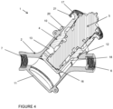
- the body 2 has a connector inlet 6 and a connector outlet 7 disposed on opposing, outer sides thereof, arranged co-axially, with their axis at around 45 degrees to the axis of the body cavity, the receptacle 4 and the mechanism 5.
- the connectors 6, 7 are adapted to connect to pipes of a plumbing system (not shown).
- the flow path 3 extends through and between the connectors 6, 7, via an inlet bore in the inlet connector 6 to an outlet bore in the outlet connector 7.
- the body 2 has at one end an opening to a cavity, the opening defined by an annular lip 10; and at an opposite end a closed base 11.
- the body cavity is adapted to receive the receptacle 4, to thereby provide a secure fit between the body 2 and the receptacle 4.
- the first lower ring 9a and the second lower ring 9b are provided on an outer circumferential surface of the receptacle 4.
- the first lower ring 9a is arranged between the inlet 12 and the outlet 13, substantially perpendicular to the longitudinal axis of the receptacle 4, such that a portion of the first lower ring 9a is provided between the inlet aperture and the chamfered section 18, and another portion of the first lower ring 9a is provided between the outlet aperture 13 and the annular rim 17.
- the second lower ring 9b is arranged below the inlet 12 and the outlet 13, adjacent the chamfered section 18, at an angle of about 45 degrees to the axis of the receptacle 4 and substantially parallel to the line between the apertures 12, 13, between both apertures 12, 13 and the receptacle base 16.
- the first lower ring 9a is arranged, in the first, operational, position, between the inlet bore and outlet bore, such that a portion of the first lower ring 9a is arranged between the inlet bore and the body base 11 and another portion of the first lower ring 9a is arranged between the outlet bore and the body cavity opening. This prevents fluid escaping from the inlet bore to the outlet bore around the receptacle 4, instead of following the intended route through the mechanism 5 within the receptacle 4. In the second position, the first lower ring 9a is arranged between the body cavity opening and the inlet bore and the outlet bore, sealing against leakage out of the body cavity opening.
- the second sealing ring 9b is arranged at an angle, in the first, operational, position, between the body base 11 and both the inlet bore and the outlet bore so as to prevent leakage into the body cavity below the receptacle 11. In the second position, the second sealing ring 9b is arranged between the two bores 6, 7 and the body cavity opening to seal against flow into the receptacle inlet and outlet apertures 12, 13.
- the plumbing fitting 1 is provided with a slide mechanism adapted to facilitate movement between the first, operational, position and the second position.
- the slide mechanism comprises a protrusion 14 provided on the body 2, which protrusion 14 projects into a guide 15 provided on a corresponding outer surface of the receptacle 4.
- the guide 15 is closed at opposite ends thereof, to prevent movement of the receptacle 4 beyond first and second end-points 15a, 15b.
- the protrusion 14 is a screw which is adapted to correspond with a first indent at the first end-point 15a and with a second indent at the second end-point 15b.
- the indents project deeper into the outer surface of the receptacle 4 than the guide 15.
- the screw 14 can be screwed via a thread in an aperture through the body 2 into the first indent to thereby secure the receptacle 4 in the first position, or into the second indent to thereby secure the receptacle 4 in the second position.
- the screw 14 can be unscrewed from the first indent and the second indent such that the receptacle 4 can be moved between the first, operational, position and the second position, with the screw 14 confined within the guide 15 and by the respective end points 15a, 15b.
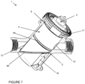
- the plumbing fitting 1 is provided with a twist lock 19 comprising first lock portions 20 provided on the body 2; and corresponding second lock portions 21 provided on the receptacle 4.
- the second lock portions 21 are adapted to interlock with the first lock portions 20.
- the plumbing fitting 1 comprises a screw 22 and thread 23 arrangement adapted to releasably secure the mechanism 5 to the receptacle 4 (as shown in Figs. 5 and 6 ). Once the mechanism 5 is secured to the receptacle 4, the receptacle 4 can be moved from the second position to the first, operational, position.
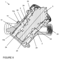
- the receptacle 4 comprises a number of internal sealing surfaces arranged to receive sealing rings 24 of the mechanism 5.
- the mechanism sealing rings 24 prevent leakage of fluid between the mechanism 5 and the receptacle cavity.
- fluid in the first, operational, position can flow via the flow path 3, into the inlet bore in the inlet connector 6, then through the inlet aperture 12 and the mechanism 5, then through the outlet aperture 13, then through the outlet bore in the outlet connector 7.
- the mechanism 5 can perform its predetermined function (e.g. in the case of a pressure independent control valve (PICV) mechanism, to control and regulate flow, and to control the pressure differential across the PICV).
- PICV pressure independent control valve
- the annular rim 17 is spaced from the annular lip 10; and the inlet 12 and the apertures 12, 13 are displaced from the inlet bore and the outlet bores, such that the chamfered section 18 is in alignment with the inlet bore.
- fluid in the second position can flow via the flow path 3 through the inlet bore in the inlet connector 6, then around the receptacle 4, then through the outlet bore in the outlet connector 7.
- fluid cannot enter the inlet 12 or the outlet 13, which are displaced from the inlet and outlet bores, and are sealed off by the sealing means 9b.
- the mechanism 5 in the second position the mechanism 5 can be accessed for maintenance or repair, as desired or required, whilst fluid flows through the flow path 3, without isolating/disconnecting the plumbing fitting 1 from the system to which it is attached.
- most regulating valves rely on the user removing the working components prior to flushing/cleaning the system. This involves draining the system in order to remove the sensitive components. If these components are not removed then flushing through them can clog the small orifices with debris or damage the workings.
- the system described allows the user to withdraw the regulating mechanism to a flushing position which is isolated from the flow. This protects the regulating mechanism from damage during flushing. The system does not need to be drained therefore simplifying and speeding up the process.
Landscapes
- Engineering & Computer Science (AREA)
- General Engineering & Computer Science (AREA)
- Mechanical Engineering (AREA)
- Health & Medical Sciences (AREA)
- Life Sciences & Earth Sciences (AREA)
- Hydrology & Water Resources (AREA)
- Public Health (AREA)
- Water Supply & Treatment (AREA)
- Quick-Acting Or Multi-Walled Pipe Joints (AREA)
- Joints Allowing Movement (AREA)
Claims (15)
- Rohrleitungsarmatur (1) aufweisend: einen Korpus (2) mit einem sich durch diesen erstreckenden Strömungskanal (3); eine in dem Korpus (2) angeordnete Buchse (4), wobei die Buchse (4) zur lösbaren Aufnahme eines Mechanismus (5) ausgebildet ist, wobei die Buchse (4) zwischen einer ersten, betätigungswirksamen Position, in der sich der Strömungskanal (3) durch die Buchse (4) und den Mechanismus (5) erstreckt, und einer zweiten Position bewegbar ist, in der der Strömungskanal (3) den Mechanismus (5) umgeht, wobei in der zweiten Position der Mechanismus (5) aus der Buchse (4) lösbar ist, während ein Fluid durch den Strömungskanal (3) strömt, wobei der Mechanismus (5) ein Steuerventil oder ein Regelventil ist.
- Rohrleitungsarmatur nach Anspruch 1, wobei der Korpus (2) einen Hohlraum aufweist, in dem die Buchse (4) angeordnet ist.
- Rohrleitungsarmatur nach Anspruch 2, wobei der Korpus (2) an einem Ende eine Öffnung (10) zum Hohlraum des Korpus und am gegenüberliegenden Ende einen geschlossenen Boden (11) aufweist und wobei die Buchse (4) einen Hohlraum aufweist, der dazu ausgelegt ist, den Mechanismus (5) lösbar aufzunehmen.
- Rohrleitungsarmatur nach einem der vorhergehenden Ansprüche, wobei der Korpus (2) einen Einlassanschluss (6) und einen Auslassanschluss (7) aufweist, wobei jeder Anschluss zum Anschließen an ein Rohrleitungssystem ausgelegt ist, wobei der Einlassanschluss (6) eine durchgehende Einlassbohrung aufweist und der Auslassanschluss (7) eine durchgehende Auslassbohrung aufweist.
- Rohrleitungsarmatur nach einem der vorhergehenden Ansprüche, wobei die Buchse (4) zwischen der ersten, betätigungswirksamen Position und der zweiten Position mittels einer Bewegungsvorrichtung bewegbar ist, die einen Gleitmechanismus (14, 15) aufweist, der dazu ausgelegt ist, die Bewegung der Buchse (4) zwischen der ersten, betätigungswirksamen Position und der zweiten Position zu begrenzen, um zu verhindern, dass die Buchse (4) aus dem Korpus (2) entfernt oder versehentlich herausgeschleudert wird.
- Rohrleitungsarmatur nach einem der vorhergehenden Ansprüche, wobei die Buchse (4) zwei oder mehr Durchbrüche aufweist, wobei die Durchbrüche einen Einlassdurchbruch (12) und einen Auslassdurchbruch (13) aufweisen.
- Rohrleitungsarmatur nach Anspruch 6, in Abhängigkeit von Anspruch 4, wobei in der ersten, betätigungswirksamen Stellung der Einlassdurchbruch (12) mit der Einlassbohrung und der Auslassdurchbruch (13) mit der Auslassbohrung fluchtet; und in der zweiten Stellung der Einlassdurchbruch (12) gegenüber der Einlassbohrung und der Auslassdurchbruch (13) gegenüber der Auslassbohrung versetzt ist.
- Rohrleitungsarmatur nach Anspruch 3, wobei die Rohrleitungsarmatur Dichtungsmittel (8, 9a, 9b) aufweist, die dazu ausgelegt sind, ein unbeabsichtigtes Austreten von Fluid zu verhindern, wobei die Dichtungsmittel (8, 9a, 9b) ein oder mehrere erste Dichtungselemente, ein oder mehrere zweite Dichtungselemente und/oder ein oder mehrere dritte Dichtungselemente aufweist und wobei in der ersten, betätigungswirksamen Position das oder jedes erste Dichtungselement dazu ausgelegt ist, ein Austreten von Fluid um die Buchse (4) herum und aus der Öffnung (10) des Hohlraums des Korpus zu verhindern.
- Rohrleitungsarmatur nach Anspruch 8, wenn sie von Anspruch 4 abhängt und wenn sie ein oder mehrere zweite Dichtungselemente aufweist, wobei der Korpus an einem Ende eine Öffnung (10) zum Hohlraum des Korpus und am gegenüberliegenden Ende einen geschlossenen Boden (11) aufweist, wobei in der ersten, betätigungswirksamen Position das oder jedes zweite Dichtungselement derart ausgebildet sein kann, dass es verhindert, dass Fluid aus der Einlassbohrung zur Auslassbohrung um die Buchse (4) herum entweicht, anstatt dem vorgesehenen Weg durch den Mechanismus (5) innerhalb der Buchse (4) zu folgen, und in der zweiten Position das oder jedes zweite Dichtungselement dazu ausgelegt ist, gegen ein Austreten aus der Öffnung (10) des Hohlraums des Korpus abzudichten.
- Rohrleitungsarmatur nach einem der vorhergehenden Ansprüche, ferner aufweisend den Mechanismus (5).
- Rohrleitungsarmatur nach Anspruch 10, wobei die Buchse (4) zwei oder mehr sekundäre Durchbrüche aufweist, die an den jeweiligen Enden eines Bypass-Weges vorgesehen sind, der sich durch die Buchse (4) erstreckt und von dem Mechanismus (5) isoliert ist.
- Rohrleitungsarmatur nach Anspruch 11, wobei im Gebrauch in der sekundären Position das Fluid durch die Einlassbohrung in den Einlassanschluss (6), dann durch den sekundären Einlassdurchbruch, dann durch den sekundären Auslassdurchbruch und dann durch die Auslassbohrung im Auslassanschluss (7) strömen kann.
- Rohrleitungsarmatur nach einem der Ansprüche 10 bis 12, wobei die Buchse (4) ein Gehäuse ist, das so angeordnet ist, dass es mindestens 40 % des Volumens des Mechanismus (5) darin lösbar umschließt.
- Rohrleitungsarmatur nach einem der vorhergehenden Ansprüche, wobei die zweite Position eine Spülposition, Wartungsposition, Instandhaltungsposition, Bypass-Position und/oder Mechanismus (5)-Austausch-Position ist.
- Rohrleitungssystem, aufweisend die Rohrleitungsarmatur (1) gemäß einem beliebigen vorhergehenden Anspruch und eine Mehrzahl von an die Rohrleitungsarmatur angeschlossenen Rohren; optional, wobei das System ein Wasserversorgungssystem, ein Entwässerungs-Entlüftungssystem, ein Abwassersystem, ein Kläranlagensystem, ein Grauwasserrückgewinnungssystem, ein Aufbereitungssystem, ein Hydroniksystem, ein Haushaltsheizungssystem oder ein Industrieheizungssystem ist.
Applications Claiming Priority (2)
| Application Number | Priority Date | Filing Date | Title |
|---|---|---|---|
| GB1815768.5A GB2577524B (en) | 2018-09-27 | 2018-09-27 | Plumbing fitting |
| PCT/GB2019/052612 WO2020065268A1 (en) | 2018-09-27 | 2019-09-17 | Plumbing fitting |
Publications (3)
| Publication Number | Publication Date |
|---|---|
| EP3856982A1 EP3856982A1 (de) | 2021-08-04 |
| EP3856982B1 true EP3856982B1 (de) | 2025-07-02 |
| EP3856982B8 EP3856982B8 (de) | 2025-08-06 |
Family
ID=64109003
Family Applications (2)
| Application Number | Title | Priority Date | Filing Date |
|---|---|---|---|
| EP19794186.7A Active EP3856982B8 (de) | 2018-09-27 | 2019-09-17 | Rohrverbindungsstück |
| EP19839109.6A Active EP3899336B1 (de) | 2018-09-27 | 2019-12-09 | Leitungsarmatur |
Family Applications After (1)
| Application Number | Title | Priority Date | Filing Date |
|---|---|---|---|
| EP19839109.6A Active EP3899336B1 (de) | 2018-09-27 | 2019-12-09 | Leitungsarmatur |
Country Status (5)
| Country | Link |
|---|---|
| US (2) | US11814822B2 (de) |
| EP (2) | EP3856982B8 (de) |
| DK (2) | DK3856982T3 (de) |
| GB (2) | GB2577524B (de) |
| WO (2) | WO2020065268A1 (de) |
Families Citing this family (2)
| Publication number | Priority date | Publication date | Assignee | Title |
|---|---|---|---|---|
| GB2615605B (en) * | 2022-02-15 | 2024-11-06 | Aalberts Integrated Piping Systems Ltd | Plumbing fitting accessory |
| GB2615604B (en) | 2022-02-15 | 2024-12-04 | Aalberts Integrated Piping Systems Ltd | Plumbing fitting |
Family Cites Families (50)
| Publication number | Priority date | Publication date | Assignee | Title |
|---|---|---|---|---|
| US839953A (en) * | 1904-02-08 | 1907-01-01 | Orville S Westerman | Gate-valve. |
| US1403056A (en) * | 1919-04-18 | 1922-01-10 | Tubular Woven Fabric Company | Valve and nozzle |
| US1597794A (en) * | 1922-11-13 | 1926-08-31 | John H Horsburgh | Quick-acting valve mechanism |
| US1713671A (en) * | 1926-06-16 | 1929-05-21 | Fyre Freez Corp | High-pressure valve |
| US1879320A (en) * | 1930-04-15 | 1932-09-27 | Henry G Klett | Valve |
| GB691430A (en) | 1951-03-21 | 1953-05-13 | Rheolaveur General Constructio | Improvements in rotary valves |
| FR1233159A (fr) * | 1959-05-28 | 1960-10-12 | Utilisation Ration Gaz | Robinet pour bouteille de gaz liquéfié |
| GB1014246A (en) | 1963-11-13 | 1965-12-22 | Audco Ltd | Improvements in and relating to plug valves |
| FR2041861A5 (de) | 1969-04-21 | 1971-02-05 | Cousin Claude | |
| US3669148A (en) * | 1969-11-24 | 1972-06-13 | Morton Norwich Products Inc | Bypass valve for fluid treating assembly |
| US3683966A (en) | 1970-04-02 | 1972-08-15 | Offshore Systems Inc | Three position valve |
| US3669147A (en) | 1971-02-18 | 1972-06-13 | Sperry Rand Corp | Power transmission |
| DE2260484A1 (de) | 1971-12-14 | 1973-06-28 | Young & Cunningham Newcast Jas | Stroemungsventil |
| US3891001A (en) | 1973-12-14 | 1975-06-24 | Irlin H Botnick | Shutoff valve with cleanout filter |
| JPS5234422U (de) * | 1975-09-02 | 1977-03-11 | ||
| IT1097714B (it) | 1977-12-21 | 1985-08-31 | Giobatta Montagnese | Valvola assiale di intercettazione |
| US4253481A (en) | 1979-05-07 | 1981-03-03 | Gilmore Valve Company | Cushioned shuttle valve |
| DE3526581C2 (de) | 1985-07-25 | 1994-06-23 | Vos Richard Grubenausbau Gmbh | Wechselventil |
| US4664152A (en) | 1986-04-04 | 1987-05-12 | Mara Michael R O | Flow control valve with replaceable cartridge subassembly having multi-tubular construction |
| DE19540580A1 (de) | 1995-10-31 | 1997-05-07 | Honeywell Ag | 3-Wege-Ventil mit Bypass |
| US5628492A (en) | 1996-02-02 | 1997-05-13 | Lee; Chung H. | Faucet connector device |
| CA2182259C (en) | 1996-07-29 | 2002-01-29 | Silvano Breda | Single lever valve and cartridge with integral mixing chamber and divided waterway |
| DE19837012C2 (de) | 1998-08-14 | 2002-04-04 | Honeywell Ag | Armatur für den Anschluß eines Wärmetauschers |
| US6458269B1 (en) * | 2000-04-20 | 2002-10-01 | Cuno Incorporated | Keyed filter assembly |
| DE20204658U1 (de) | 2002-03-22 | 2003-07-31 | Watts Dumser GmbH & Co.KG, 76829 Landau | Absperrvorrichtung für einen mit einem flüssigen Medium betriebenen Kreislauf einer Wärme- oder Kälteversorgungsanlage, insbesondere Absperrventil |
| US6913033B2 (en) | 2003-04-03 | 2005-07-05 | Silvano Breda | Diverter valve with removable cartridge including integral atmospheric type vacuum breaker and check |
| CN2859117Y (zh) | 2005-09-22 | 2007-01-17 | 安徽铜都阀门有限公司 | 一种轨道式无摩擦蝶阀 |
| CN201078483Y (zh) | 2007-08-08 | 2008-06-25 | 安徽铜都阀门有限公司 | 一种提升式单副密封旋塞阀 |
| US7959010B2 (en) | 2008-03-14 | 2011-06-14 | Cummins Filtration Ip, Inc. | Standpipe with integrated regulator valve |
| CN202074068U (zh) | 2011-05-07 | 2011-12-14 | 浙江万龙机械有限公司 | 用于导向槽式升降杆球阀的阀杆 |
| US8950052B2 (en) * | 2011-09-15 | 2015-02-10 | Whirlpool Corporation | Method of installing a filter unit |
| DE102011116627B3 (de) | 2011-10-20 | 2012-10-18 | Gea Tuchenhagen Gmbh | Betätigungsvorrichtung für einen drehbaren Verschlussteil eines Ventils |
| CN202371205U (zh) | 2011-12-19 | 2012-08-08 | 科福龙阀门集团有限公司 | 滚动式轨道球阀 |
| WO2013144459A1 (fr) | 2012-03-30 | 2013-10-03 | Cummins Filtration Sarl | Ensemble de filtrage comportant une cartouche de filtration, et cartouche de filtration correspondante |
| KR101168755B1 (ko) | 2012-06-12 | 2012-07-26 | 주식회사 신영정보기술 | 복합유량조절밸브 |
| CN203309176U (zh) | 2013-06-20 | 2013-11-27 | 球豹阀门有限公司 | 一种轨道式硬密封球阀 |
| ITMI20131047A1 (it) | 2013-06-24 | 2014-12-25 | Vir Valvoindustria Ing Rizzio S P A | Valvola di by-pass |
| CN203532865U (zh) | 2013-10-11 | 2014-04-09 | 王泉卫 | 一种过滤三通球阀 |
| WO2015173811A1 (en) | 2014-05-14 | 2015-11-19 | S.P.C. Tech Ltd. | Fluid pipe hub |
| DE102015103662A1 (de) | 2015-03-12 | 2016-09-15 | Hengst Se & Co. Kg | Filter mit einem Filterumgehungsventil und Filtereinsatz dafür |
| CN205013774U (zh) | 2015-10-08 | 2016-02-03 | 江苏神通阀门股份有限公司 | 一种止回阀 |
| KR101769207B1 (ko) | 2015-10-13 | 2017-08-18 | 허남욱 | 핫러너 사출금형의 게이트 밸브장치 |
| ITUB20160668A1 (it) * | 2016-02-11 | 2017-08-11 | Ceadesign Srl | Collettore perfezionato per gruppi di erogazione |
| CN205401805U (zh) | 2016-03-14 | 2016-07-27 | 太仓优尼泰克精密机械有限公司 | 一种双轨道槽硬密封球阀 |
| GB2548810B (en) | 2016-03-23 | 2018-08-15 | Peerless Gas Controls Ltd | Gas valve |
| CN206708463U (zh) | 2017-05-23 | 2017-12-05 | 济宁鲁威液压科技股份有限公司 | 大流量调压二通插装单向阀 |
| CN206708390U (zh) | 2017-05-23 | 2017-12-05 | 济宁鲁威液压科技股份有限公司 | 大流量先导式电磁截止阀 |
| CN107489785A (zh) | 2017-07-19 | 2017-12-19 | 浙江大学 | 一种可拆卸式球阀结构 |
| US10584040B2 (en) * | 2017-10-06 | 2020-03-10 | Whirlpool Corporation | Filter cartridge |
| KR101867954B1 (ko) | 2018-02-21 | 2018-06-20 | 주식회사 정아유압 | 로터리 액츄에이터 |
-
2018
- 2018-09-27 GB GB1815768.5A patent/GB2577524B/en active Active
- 2018-12-19 GB GB1820706.8A patent/GB2577575B/en active Active
-
2019
- 2019-09-17 WO PCT/GB2019/052612 patent/WO2020065268A1/en not_active Ceased
- 2019-09-17 US US17/279,826 patent/US11814822B2/en active Active
- 2019-09-17 DK DK19794186.7T patent/DK3856982T3/da active
- 2019-09-17 EP EP19794186.7A patent/EP3856982B8/de active Active
- 2019-12-09 EP EP19839109.6A patent/EP3899336B1/de active Active
- 2019-12-09 DK DK19839109.6T patent/DK3899336T3/da active
- 2019-12-09 US US17/413,987 patent/US20220056676A1/en not_active Abandoned
- 2019-12-09 WO PCT/GB2019/053462 patent/WO2020128427A1/en not_active Ceased
Also Published As
| Publication number | Publication date |
|---|---|
| EP3856982A1 (de) | 2021-08-04 |
| GB201815768D0 (en) | 2018-11-14 |
| GB2577524A (en) | 2020-04-01 |
| GB2577524B (en) | 2021-01-20 |
| GB2577575A (en) | 2020-04-01 |
| GB2577575B (en) | 2023-08-02 |
| EP3899336B1 (de) | 2025-08-06 |
| US20220056676A1 (en) | 2022-02-24 |
| EP3899336A1 (de) | 2021-10-27 |
| GB201820706D0 (en) | 2019-01-30 |
| US11814822B2 (en) | 2023-11-14 |
| US20210340741A1 (en) | 2021-11-04 |
| EP3856982B8 (de) | 2025-08-06 |
| DK3899336T3 (da) | 2025-09-29 |
| DK3856982T3 (da) | 2025-08-18 |
| WO2020128427A1 (en) | 2020-06-25 |
| WO2020065268A1 (en) | 2020-04-02 |
Similar Documents
| Publication | Publication Date | Title |
|---|---|---|
| US7981289B2 (en) | Modular fluid treatment apparatus and method | |
| EP1861189B1 (de) | Unter verwendung eines verbindungsstücks leicht austauschbares wasserreingungsfilter | |
| AU2014235855B2 (en) | Filter assembly | |
| US20160144301A1 (en) | Modular multimedia fluid treatment system | |
| EP3332855B1 (de) | Filter- und schmutzabscheideanlage | |
| CN101437592A (zh) | 过滤器组件 | |
| CN104837729A (zh) | 飞行器厨房管道系统及其饮用水过滤器和分配安装歧管 | |
| EP3449995A1 (de) | Schlammfiltervorrichtung | |
| CN113750625A (zh) | 具有键接接合的水过滤器滤筒和头部 | |
| US11814822B2 (en) | Plumbing fitting | |
| CN106830107B (zh) | 用于流体处理装置的控制阀 | |
| WO2011153607A1 (en) | Debris filtering apparatus and method | |
| EP2142829B1 (de) | Hahn | |
| EP2952791B1 (de) | Verteilermodul und filteranordnung | |
| GB2448418A (en) | A filter unit | |
| EP2365853B1 (de) | Filteranordnungen | |
| KR200190745Y1 (ko) | 정수기용 필터어셈블리 | |
| HK40063368A (en) | Water filter cartridge and head having keyed engagement | |
| KR200304283Y1 (ko) | 정수기용 필터 | |
| GB2480751A (en) | Aquarium filtering system comprising detachably connected filter assembly and distribution housing. | |
| HK40056773A (en) | Control valve for fluid treatment apparatus | |
| HK40056774A (en) | Control valve for fluid treatment apparatus | |
| HK40056774B (en) | Control valve for fluid treatment apparatus | |
| HK1237330A1 (en) | Control valve for fluid treatment apparatus |
Legal Events
| Date | Code | Title | Description |
|---|---|---|---|
| STAA | Information on the status of an ep patent application or granted ep patent |
Free format text: STATUS: UNKNOWN |
|
| STAA | Information on the status of an ep patent application or granted ep patent |
Free format text: STATUS: THE INTERNATIONAL PUBLICATION HAS BEEN MADE |
|
| PUAI | Public reference made under article 153(3) epc to a published international application that has entered the european phase |
Free format text: ORIGINAL CODE: 0009012 |
|
| STAA | Information on the status of an ep patent application or granted ep patent |
Free format text: STATUS: REQUEST FOR EXAMINATION WAS MADE |
|
| 17P | Request for examination filed |
Effective date: 20210423 |
|
| AK | Designated contracting states |
Kind code of ref document: A1 Designated state(s): AL AT BE BG CH CY CZ DE DK EE ES FI FR GB GR HR HU IE IS IT LI LT LU LV MC MK MT NL NO PL PT RO RS SE SI SK SM TR |
|
| RAP3 | Party data changed (applicant data changed or rights of an application transferred) |
Owner name: AALBERTS INTEGRATED PIPING SYSTEMS LIMITED |
|
| DAV | Request for validation of the european patent (deleted) | ||
| DAX | Request for extension of the european patent (deleted) | ||
| STAA | Information on the status of an ep patent application or granted ep patent |
Free format text: STATUS: EXAMINATION IS IN PROGRESS |
|
| 17Q | First examination report despatched |
Effective date: 20230301 |
|
| GRAP | Despatch of communication of intention to grant a patent |
Free format text: ORIGINAL CODE: EPIDOSNIGR1 |
|
| STAA | Information on the status of an ep patent application or granted ep patent |
Free format text: STATUS: GRANT OF PATENT IS INTENDED |
|
| RIC1 | Information provided on ipc code assigned before grant |
Ipc: F16K 43/00 20060101ALI20250121BHEP Ipc: F16K 3/26 20060101ALI20250121BHEP Ipc: F16K 31/528 20060101ALI20250121BHEP Ipc: E03B 7/07 20060101AFI20250121BHEP |
|
| INTG | Intention to grant announced |
Effective date: 20250203 |
|
| GRAS | Grant fee paid |
Free format text: ORIGINAL CODE: EPIDOSNIGR3 |
|
| GRAA | (expected) grant |
Free format text: ORIGINAL CODE: 0009210 |
|
| STAA | Information on the status of an ep patent application or granted ep patent |
Free format text: STATUS: THE PATENT HAS BEEN GRANTED |
|
| AK | Designated contracting states |
Kind code of ref document: B1 Designated state(s): AL AT BE BG CH CY CZ DE DK EE ES FI FR GB GR HR HU IE IS IT LI LT LU LV MC MK MT NL NO PL PT RO RS SE SI SK SM TR |
|
| REG | Reference to a national code |
Ref country code: GB Ref legal event code: FG4D |
|
| REG | Reference to a national code |
Ref country code: CH Ref legal event code: EP Ref country code: CH Ref legal event code: PK Free format text: BERICHTIGUNG B8 |
|
| P01 | Opt-out of the competence of the unified patent court (upc) registered |
Free format text: CASE NUMBER: APP_27466/2025 Effective date: 20250610 |
|
| RBV | Designated contracting states (corrected) |
Designated state(s): AL AT BE BG CH CY CZ DE DK EE ES FI FR GR HR HU IE IS IT LI LT LU LV MC MK MT NL NO PL PT RO RS SE SI SK SM TR |
|
| REG | Reference to a national code |
Ref country code: DE Ref legal event code: R096 Ref document number: 602019071982 Country of ref document: DE |
|
| REG | Reference to a national code |
Ref country code: IE Ref legal event code: FG4D |
|
| REG | Reference to a national code |
Ref country code: SE Ref legal event code: TRGR |
|
| REG | Reference to a national code |
Ref country code: NL Ref legal event code: FP |
|
| REG | Reference to a national code |
Ref country code: DK Ref legal event code: T3 Effective date: 20250806 |
|
| PGFP | Annual fee paid to national office [announced via postgrant information from national office to epo] |
Ref country code: DK Payment date: 20250721 Year of fee payment: 7 |
|
| PGFP | Annual fee paid to national office [announced via postgrant information from national office to epo] |
Ref country code: NL Payment date: 20250926 Year of fee payment: 7 |
|
| PGFP | Annual fee paid to national office [announced via postgrant information from national office to epo] |
Ref country code: BE Payment date: 20250925 Year of fee payment: 7 |
|
| PGFP | Annual fee paid to national office [announced via postgrant information from national office to epo] |
Ref country code: FR Payment date: 20250731 Year of fee payment: 7 |
|
| PGFP | Annual fee paid to national office [announced via postgrant information from national office to epo] |
Ref country code: SE Payment date: 20250731 Year of fee payment: 7 |
|
| PG25 | Lapsed in a contracting state [announced via postgrant information from national office to epo] |
Ref country code: PT Free format text: LAPSE BECAUSE OF FAILURE TO SUBMIT A TRANSLATION OF THE DESCRIPTION OR TO PAY THE FEE WITHIN THE PRESCRIBED TIME-LIMIT Effective date: 20251103 |
|
| REG | Reference to a national code |
Ref country code: AT Ref legal event code: MK05 Ref document number: 1809391 Country of ref document: AT Kind code of ref document: T Effective date: 20250702 |
|
| PG25 | Lapsed in a contracting state [announced via postgrant information from national office to epo] |
Ref country code: IS Free format text: LAPSE BECAUSE OF FAILURE TO SUBMIT A TRANSLATION OF THE DESCRIPTION OR TO PAY THE FEE WITHIN THE PRESCRIBED TIME-LIMIT Effective date: 20251102 |
|
| PGFP | Annual fee paid to national office [announced via postgrant information from national office to epo] |
Ref country code: DE Payment date: 20250930 Year of fee payment: 7 |
|
| PG25 | Lapsed in a contracting state [announced via postgrant information from national office to epo] |
Ref country code: NO Free format text: LAPSE BECAUSE OF FAILURE TO SUBMIT A TRANSLATION OF THE DESCRIPTION OR TO PAY THE FEE WITHIN THE PRESCRIBED TIME-LIMIT Effective date: 20251002 |
|
| REG | Reference to a national code |
Ref country code: LT Ref legal event code: MG9D |
|
| PG25 | Lapsed in a contracting state [announced via postgrant information from national office to epo] |
Ref country code: AT Free format text: LAPSE BECAUSE OF FAILURE TO SUBMIT A TRANSLATION OF THE DESCRIPTION OR TO PAY THE FEE WITHIN THE PRESCRIBED TIME-LIMIT Effective date: 20250702 |
|
| PG25 | Lapsed in a contracting state [announced via postgrant information from national office to epo] |
Ref country code: FI Free format text: LAPSE BECAUSE OF FAILURE TO SUBMIT A TRANSLATION OF THE DESCRIPTION OR TO PAY THE FEE WITHIN THE PRESCRIBED TIME-LIMIT Effective date: 20250702 |
|
| PG25 | Lapsed in a contracting state [announced via postgrant information from national office to epo] |
Ref country code: HR Free format text: LAPSE BECAUSE OF FAILURE TO SUBMIT A TRANSLATION OF THE DESCRIPTION OR TO PAY THE FEE WITHIN THE PRESCRIBED TIME-LIMIT Effective date: 20250702 |
|
| PG25 | Lapsed in a contracting state [announced via postgrant information from national office to epo] |
Ref country code: GR Free format text: LAPSE BECAUSE OF FAILURE TO SUBMIT A TRANSLATION OF THE DESCRIPTION OR TO PAY THE FEE WITHIN THE PRESCRIBED TIME-LIMIT Effective date: 20251003 |
|
| PG25 | Lapsed in a contracting state [announced via postgrant information from national office to epo] |
Ref country code: CZ Free format text: LAPSE BECAUSE OF FAILURE TO SUBMIT A TRANSLATION OF THE DESCRIPTION OR TO PAY THE FEE WITHIN THE PRESCRIBED TIME-LIMIT Effective date: 20250702 |
|
| PG25 | Lapsed in a contracting state [announced via postgrant information from national office to epo] |
Ref country code: LV Free format text: LAPSE BECAUSE OF FAILURE TO SUBMIT A TRANSLATION OF THE DESCRIPTION OR TO PAY THE FEE WITHIN THE PRESCRIBED TIME-LIMIT Effective date: 20250702 |
|
| PG25 | Lapsed in a contracting state [announced via postgrant information from national office to epo] |
Ref country code: BG Free format text: LAPSE BECAUSE OF FAILURE TO SUBMIT A TRANSLATION OF THE DESCRIPTION OR TO PAY THE FEE WITHIN THE PRESCRIBED TIME-LIMIT Effective date: 20250702 Ref country code: PL Free format text: LAPSE BECAUSE OF FAILURE TO SUBMIT A TRANSLATION OF THE DESCRIPTION OR TO PAY THE FEE WITHIN THE PRESCRIBED TIME-LIMIT Effective date: 20250702 |
|
| PG25 | Lapsed in a contracting state [announced via postgrant information from national office to epo] |
Ref country code: RS Free format text: LAPSE BECAUSE OF FAILURE TO SUBMIT A TRANSLATION OF THE DESCRIPTION OR TO PAY THE FEE WITHIN THE PRESCRIBED TIME-LIMIT Effective date: 20251002 |
|
| PG25 | Lapsed in a contracting state [announced via postgrant information from national office to epo] |
Ref country code: ES Free format text: LAPSE BECAUSE OF FAILURE TO SUBMIT A TRANSLATION OF THE DESCRIPTION OR TO PAY THE FEE WITHIN THE PRESCRIBED TIME-LIMIT Effective date: 20250702 |
|
| PG25 | Lapsed in a contracting state [announced via postgrant information from national office to epo] |
Ref country code: RO Free format text: LAPSE BECAUSE OF FAILURE TO SUBMIT A TRANSLATION OF THE DESCRIPTION OR TO PAY THE FEE WITHIN THE PRESCRIBED TIME-LIMIT Effective date: 20250702 |
|
| PG25 | Lapsed in a contracting state [announced via postgrant information from national office to epo] |
Ref country code: SM Free format text: LAPSE BECAUSE OF FAILURE TO SUBMIT A TRANSLATION OF THE DESCRIPTION OR TO PAY THE FEE WITHIN THE PRESCRIBED TIME-LIMIT Effective date: 20250702 |
|
| PG25 | Lapsed in a contracting state [announced via postgrant information from national office to epo] |
Ref country code: IT Free format text: LAPSE BECAUSE OF FAILURE TO SUBMIT A TRANSLATION OF THE DESCRIPTION OR TO PAY THE FEE WITHIN THE PRESCRIBED TIME-LIMIT Effective date: 20250702 |
|
| PG25 | Lapsed in a contracting state [announced via postgrant information from national office to epo] |
Ref country code: SK Free format text: LAPSE BECAUSE OF FAILURE TO SUBMIT A TRANSLATION OF THE DESCRIPTION OR TO PAY THE FEE WITHIN THE PRESCRIBED TIME-LIMIT Effective date: 20250702 |
|
| REG | Reference to a national code |
Ref country code: CH Ref legal event code: H13 Free format text: ST27 STATUS EVENT CODE: U-0-0-H10-H13 (AS PROVIDED BY THE NATIONAL OFFICE) Effective date: 20260504 |
|
| PLBE | No opposition filed within time limit |
Free format text: ORIGINAL CODE: 0009261 |
|
| STAA | Information on the status of an ep patent application or granted ep patent |
Free format text: STATUS: NO OPPOSITION FILED WITHIN TIME LIMIT |