EP3855635A1 - Csi-bericht auf basis eines port-codebuchs mit linearer kombination - Google Patents
Csi-bericht auf basis eines port-codebuchs mit linearer kombination Download PDFInfo
- Publication number
- EP3855635A1 EP3855635A1 EP20153656.2A EP20153656A EP3855635A1 EP 3855635 A1 EP3855635 A1 EP 3855635A1 EP 20153656 A EP20153656 A EP 20153656A EP 3855635 A1 EP3855635 A1 EP 3855635A1
- Authority
- EP
- European Patent Office
- Prior art keywords
- receiver
- port
- feedback
- matrix
- vector
- Prior art date
- Legal status (The legal status is an assumption and is not a legal conclusion. Google has not performed a legal analysis and makes no representation as to the accuracy of the status listed.)
- Withdrawn
Links
Images


Classifications
-
- H—ELECTRICITY
- H04—ELECTRIC COMMUNICATION TECHNIQUE
- H04B—TRANSMISSION
- H04B7/00—Radio transmission systems, i.e. using radiation field
- H04B7/02—Diversity systems; Multi-antenna system, i.e. transmission or reception using multiple antennas
- H04B7/04—Diversity systems; Multi-antenna system, i.e. transmission or reception using multiple antennas using two or more spaced independent antennas
- H04B7/06—Diversity systems; Multi-antenna system, i.e. transmission or reception using multiple antennas using two or more spaced independent antennas at the transmitting station
- H04B7/0613—Diversity systems; Multi-antenna system, i.e. transmission or reception using multiple antennas using two or more spaced independent antennas at the transmitting station using simultaneous transmission
- H04B7/0615—Diversity systems; Multi-antenna system, i.e. transmission or reception using multiple antennas using two or more spaced independent antennas at the transmitting station using simultaneous transmission of weighted versions of same signal
- H04B7/0619—Diversity systems; Multi-antenna system, i.e. transmission or reception using multiple antennas using two or more spaced independent antennas at the transmitting station using simultaneous transmission of weighted versions of same signal using feedback from receiving side
- H04B7/0636—Feedback format
- H04B7/0639—Using selective indices, e.g. of a codebook, e.g. pre-distortion matrix index [PMI] or for beam selection
-
- H—ELECTRICITY
- H04—ELECTRIC COMMUNICATION TECHNIQUE
- H04B—TRANSMISSION
- H04B7/00—Radio transmission systems, i.e. using radiation field
- H04B7/02—Diversity systems; Multi-antenna system, i.e. transmission or reception using multiple antennas
- H04B7/04—Diversity systems; Multi-antenna system, i.e. transmission or reception using multiple antennas using two or more spaced independent antennas
- H04B7/0413—MIMO systems
- H04B7/0456—Selection of precoding matrices or codebooks, e.g. using matrices antenna weighting
- H04B7/0478—Special codebook structures directed to feedback optimisation
-
- H—ELECTRICITY
- H04—ELECTRIC COMMUNICATION TECHNIQUE
- H04B—TRANSMISSION
- H04B7/00—Radio transmission systems, i.e. using radiation field
- H04B7/02—Diversity systems; Multi-antenna system, i.e. transmission or reception using multiple antennas
- H04B7/04—Diversity systems; Multi-antenna system, i.e. transmission or reception using multiple antennas using two or more spaced independent antennas
- H04B7/06—Diversity systems; Multi-antenna system, i.e. transmission or reception using multiple antennas using two or more spaced independent antennas at the transmitting station
- H04B7/0613—Diversity systems; Multi-antenna system, i.e. transmission or reception using multiple antennas using two or more spaced independent antennas at the transmitting station using simultaneous transmission
- H04B7/0615—Diversity systems; Multi-antenna system, i.e. transmission or reception using multiple antennas using two or more spaced independent antennas at the transmitting station using simultaneous transmission of weighted versions of same signal
- H04B7/0619—Diversity systems; Multi-antenna system, i.e. transmission or reception using multiple antennas using two or more spaced independent antennas at the transmitting station using simultaneous transmission of weighted versions of same signal using feedback from receiving side
- H04B7/0621—Feedback content
- H04B7/0634—Antenna weights or vector/matrix coefficients
Definitions
- the present application concerns the field of wireless communications, more specifically to feedback reporting for a codebook-based precoding in a wireless communication system.
- Fig. 1 is a schematic representation of a terrestrial wireless network 100 including, as is shown in Fig. 1(a) , a core network 102 and one or more radio access networks RAN 1 , RAN 2 , ...RAN N .
- Fig. 1(b) is a schematic representation of a radio access network 104 that may include one or more base stations gNB 1 to gNB 5 , each serving a specific area surrounding the base station schematically represented by respective cells 106 1 to 106 5 .
- the base stations are provided to serve users within a cell.
- the term base station, BS refers to a gNB in 5G networks, eNB in UMTS/LTE/LTE-A/ LTE-A Pro, or just BS in other mobile communication standards.
- a user may be a stationary device or a mobile device which connects to a base station or to a user.
- the mobile device may include a physical device, like a user equipment, UE; or a loT device, a ground based vehicle, such as a robot or a car, an aerial vehicle, such as a manned or unmanned aerial vehicle (UAV), the latter also referred to as drone, a building or any other item or device having embedded network connectivity that enables collecting or exchanging data across an existing network infrastructure, like a device including certain electronics, software, sensors, actuators, or the like.
- Fig. 1 shows only five cells, however, the wireless communication system may include more such cells.
- Fig. 1 shows two users UE 1 and UE 2 , also referred to as user equipment, UE, that are in cell 106 2 and that are served by base station gNB 2 .
- FIG. 1 shows two loT devices 110 1 and 110 2 in cell 106 4 , which may be stationary or mobile devices.
- the loT device 110 1 accesses the wireless communication system via the base station gNB 4 to receive and transmit data as schematically represented by arrow 112 1 .
- the loT device 110 2 accesses the wireless communication system via the user UE 3 as is schematically represented by arrow 112 2 .
- the respective base station gNB 1 to gNB 5 may be connected to the core network 102, e.g. via the S1 interface, via respective backhaul links 114 1 to 114 5 , which are schematically represented in Fig. 1 by the arrows pointing to "core”.
- the core network 102 may be connected to one or more external networks. Further, some or all of the respective base station gNB 1 to gNB 5 may connected, e.g. via the S1 or X2 interface or XN interface in NR, with each other via respective backhaul links 116 1 to 116 5 , which are schematically represented in Fig. 1 by the arrows pointing to "gNBs".
- the physical resource grid may comprise a set of resource elements to which various physical channels and physical signals are mapped.
- the physical channels may include the physical downlink, uplink and/or sidelink, SL, shared channels (PDSCH, PUSCH, PSSCH) carrying user specific data, also referred to as downlink, uplink or sidelink payload data, the physical broadcast channel (PBCH) carrying for example a master information block (MIB) and a system information block (SIB), the physical downlink, uplink and/or sidelink control channels (PDCCH, PUCCH, PSCCH) carrying for example the downlink control information (DCI), the uplink control information (UCI) or the sidelink control information (SCI).
- PBCH physical broadcast channel
- MIB master information block
- SIB system information block
- PDCCH, PUCCH, PSCCH carrying for example the downlink control information (DCI), the uplink control information (UCI) or the sidelink control information (SCI).
- DCI downlink control information
- UCI uplink control information
- the physical channels may further include the physical random access channel (PRACH or RACH) used by UEs for accessing the network once a UE is synchronized and obtains the MIB and SIB.
- the physical signals may comprise reference signals or symbols (RS), synchronization signals and the like.
- the resource grid may comprise a frame or radio frame having a certain duration, like 10 milliseconds, in the time domain and having a given bandwidth in the frequency domain.
- the frame may have a certain number of subframes of a predefined length, e.g., 2 subframes with a length of 1 millisecond. Each subframe may include two slots of 6 or 7 OFDM symbols depending on the cyclic prefix (CP) length.
- a frame may also include or consist of a smaller number of OFDM symbols, e.g. when utilizing shortened transmission time intervals (sTTI) or a mini-slot/non-slot-based frame structure comprising just a few OFDM symbols.
- sTTI shortened transmission time interval
- the wireless communication system may be any single-tone or multicarrier system using frequency-division multiplexing, like the orthogonal frequency-division multiplexing (OFDM) system, the orthogonal frequency-division multiple access (OFDMA) system, or any other IFFT-based signal with or without CP, e.g. DFT-s-OFDM.
- Other waveforms like non-orthogonal waveforms for multiple access, e.g. filter-bank multicarrier (FBMC), generalized frequency division multiplexing (GFDM) or universal filtered multi carrier (UFMC), may be used.
- FBMC filter-bank multicarrier
- GFDM generalized frequency division multiplexing
- UFMC universal filtered multi carrier
- the wireless communication system may operate, e.g., in accordance with the LTE-Advanced pro standard or the 5G or NR, New Radio, standard.
- the wireless network or communication system depicted in Fig. 1 may by a heterogeneous network having two distinct overlaid networks, a network of macro cells with each macro cell including a macro base station, like base station gNB 1 to gNB 5 , and a network of small cell base stations (not shown in Fig. 1 ), like femto- or pico-base stations.
- a network of macro cells with each macro cell including a macro base station, like base station gNB 1 to gNB 5 , and a network of small cell base stations (not shown in Fig. 1 ), like femto- or pico-base stations.
- non-terrestrial wireless communication networks exist including spaceborne transceivers, like satellites, and/or airborne transceivers, like unmanned aircraft systems.
- the non-terrestrial wireless communication network or system may operate in a similar way as the terrestrial system described above with reference to Fig. 1 , for example in accordance with the LTE-advanced pro standard or the
- multi-antenna techniques may be used, e.g., in accordance with LTE, NR or any other communication system, to improve user data rates, link reliability, cell coverage and network capacity.
- linear precoding is used in the physical layer of the communication system. Linear precoding is performed by a precoder matrix which maps layers of data to antenna ports.
- the precoding may be seen as a generalization of beamforming, which is a technique to spatially direct or focus a data transmission towards an intended receiver.
- the precoder matrix to be used at the gNB to map the data to the transmit antenna ports is decided using channel state information, CSI.
- downlink signals convey data signals, control signals containing downlink, DL, control information (DCI), and a number of reference signals or symbols (RS) used for different purposes.
- a gNodeB (or gNB or base station) transmits data and downlink control information (DCI) through the so-called physical downlink shared channel (PDSCH) and physical downlink control channel (PDCCH) or enhanced PDCCH (ePDCCH), respectively.
- PDSCH physical downlink shared channel
- PDCCH physical downlink control channel
- ePDCCH enhanced PDCCH
- the downlink signal(s) of the gNB may contain one or multiple types of RSs including a common RS (CRS) in LTE, a channel state information RS (CSI-RS), a demodulation RS (DM-RS), and a phase tracking RS (PT-RS).
- CRS is transmitted over a DL system bandwidth part and used at the user equipment (UE) to obtain a channel estimate to demodulate the data or control information.
- the CSI-RS is transmitted with a reduced density in the time and frequency domain compared to CRS and used at the UE for channel estimation or for channel state information (CSI) acquisition.
- the DM-RS is transmitted only in a bandwidth part of the respective PDSCH and used by the UE for data demodulation.
- CSI-RS reporting mechanisms For signal precoding at the gNB, several CSI-RS reporting mechanisms are used such as non-precoded CSI-RS and beamformed CSI-RS reporting (see reference [1]).
- a non-precoded CSI-RS a one-to-one mapping between a CSI-RS port and a transceiver unit, TXRU, of the antenna array at the gNB is utilized. Therefore, non-precoded CSI-RS provides a cell-wide coverage where the different CSI-RS ports have the same beam direction and beam width.
- beamformed/precoded UE-specific or non-UE-specific CSI-RS a beamforming operation is applied over a single antenna ports or over multiple antenna ports to have several narrow beams with high gain in different directions and, therefore, no cell-wide coverage.
- CSI channel state information
- gNB base station
- FDD frequency division duplexing
- the channel is estimated at the UE and the estimate is fed back to the gNB.
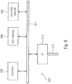
- Fig. 2 shows a block-based model of a MIMO DL transmission using codebook-based-precoding in accordance with LTE release 8.
- Fig. 2 shows schematically the base station 200, gNB, the user equipment, UE, 202 and the channel 204, like a radio channel for a wireless data communication between the base station 200 and the user equipment 202.
- the base station includes an antenna array ANT T having a plurality of antennas or antenna elements, and a precoder 206 receiving a data vector 208 and a precoder matrix F from a codebook 210.
- the channel 204 may be described by the channel tensor/matrix 212.
- the user equipment 202 receives the data vector 214 via an antenna or an antenna array ANT R having a plurality of antennas or antenna elements.
- a feedback channel 216 between the user equipment 202 and the base station 200 is provided for transmitting feedback information.
- the previous releases of 3GPP up to Rel.15 support the use of several downlink reference symbols (such as CSI-RS) for CSI estimation at the UE.
- CSI-RS downlink reference symbols
- the estimated channel at the UE is reported to the gNB implicitly where the CSI report transmitted by the UE over the feedback channel includes the rank index (RI), the precoding matrix index (PMI) and the channel quality index (CQI) (and the CRI from Rel. 13) allowing, at the gNB, to decide the precoding matrix, and the modulation order and coding scheme (MCS) of the symbols to be transmitted.
- the PMI and the RI are used to determine the precoding matrix from a predefined set of matrices ⁇ also referred to as codebook.
- the codebook may be a look-up table with matrices in each entry of the table, and the PMI and RI from the UE decide from which row and column of the table the precoder matrix to be used is obtained.
- the ULA allows controlling the radio wave in the horizontal (azimuth) direction only, so that azimuth-only beamforming at the gNB is possible, whereas the UPA supports transmit beamforming on both vertical (elevation) and horizontal (azimuth) directions, which is also referred to as full-dimension (FD) MIMO.
- the codebook e.g., in the case of massive antenna arrays such as FD-MIMO, may be a set of beamforming weights that forms spatially separated electromagnetic transmit/receive beams using the array response vectors of the array.
- the beamforming weights (also referred to as the array steering vectors) of the array are amplitude gains and phase adjustments that are applied to the signal fed to the antennas (or the signal received from the antennas) to transmit (or obtain) a radiation towards (or from) a particular direction.
- the components of the precoder matrix are obtained from the codebook, and the PMI and the RI are used to read the codebook and obtain the precoder.
- the array steering vectors may be described by the columns of a 2D Discrete Fourier Transform (DFT) matrix when ULAs or UPAs are used for signal transmission.
- DFT Discrete Fourier Transform
- the first component or the so-called first stage precoder, F 1 is used to select a number of beam vectors and (if configured) rotation oversampling factors from a Discrete Fourier Transform-based (DFT-based) matrix, which is also called the spatial codebook.
- DFT-based Discrete Fourier Transform-based
- the first component or the so-called first stage precoder, F 1 is used to select a number of spatial domain (SD) or beam vectors and the rotation oversampling factors from a Discrete Fourier Transform-based (DFT-based) matrix which is also called the spatial codebook.
- the spatial codebook comprises an oversampled DFT matrix of dimension N 1 N 2 ⁇ N 1 O 1 N 2 O 2 , where O 1 and O 2 denote the oversampling factors with respect to the first and second dimension of the codebook, respectively.
- the DFT vectors in the codebook are grouped into ( q 1 , q 2 ), 0 ⁇ q 1 ⁇ O 1 - 1, 0 ⁇ q 2 ⁇ O 2 - 1 subgroups, where each subgroup contains N 1 N 2 DFT vectors, and the parameters q 1 and q 2 are denoted as the rotation oversampling factors, with respect to the first and second dimension of the antenna array, respectively.
- the second component or the so-called second stage precoder, F 2 ( s ), is used to combine the selected beam vectors.
- F 2 ( s ) is given for a dual-polarized antenna array by (see reference [1])
- F 2 s e u e j ⁇ 1 e u ⁇ C 2 L ⁇ 1 , where e u ⁇ C L ⁇ 1 contains zeros at all positions, except the u-th position which is one.
- e u selects the u-th vector in F 1 per polarization of the antenna.
- e j ⁇ 1 is a quantized phase adjustment for the second polarization of the antenna array.
- F 2 ( s ) is given for dual-polarized antenna arrays by (see reference [1])
- F 2 s e j ⁇ o p 0 ⁇ e j ⁇ 2 L ⁇ 1 p 2 L ⁇ 1 ⁇ C 2 L ⁇ 1
- F 2 ( s ) contains R vectors, where the entries of each vector are chosen to combine single or multiple beams within each polarization.
- the selection of the matrices F 1 and F 2 ( s ) is performed by the UE based on the knowledge of the channel conditions.
- the selected matrices are indicated in the CSI report in the form of a RI and a PMI, which are used at the gNB to update the multi-user precoder for the next transmission time interval.
- a subband refers to a group of adjacent physical resource blocks (PRBs).
- PRBs physical resource blocks
- the first component represented by the matrix F 1
- the second component represented by the matrix F 3 r
- the second component represented by the matrix F 3 r
- DD delay domain
- DFT-based Discrete Fourier Transform-based
- the third component represented by the matrix F 2 r , contains a number of combining coefficients that are used to combine the selected SD basis vectors and DD basis vectors from the spatial and delay codebooks, respectively.
- the current 3GPP Type-I and Type-II CSI reporting schemes are mainly used in frequency division duplex (FDD) system configurations and do not exploit properties of uplink/downlink channel reciprocity. Contrary to FDD system configurations, channel reciprocity is mainly applicable in time division duplex (TDD) systems in which the same carrier is used for uplink and downlink transmissions.
- TDD time division duplex
- Channel measurements performed in the uplink at the base station (gNB) may be used to support downlink transmissions, for example downlink beamforming, without additional feedback or with reduced feedback from the UE.
- channel reciprocity is usually not satisfied since the duplex distance between the uplink and the downlink carriers may be larger than the channel coherence bandwidth.
- a known approach to obtain CSI even in FDD systems at the base station without UE assistance is based on channel extrapolation (see references [6] and [7]). There, it is assumed that the downlink channel and/or its multipath parameters may be calculated by an extrapolation of the channel response (or its multipath parameters) measured in the uplink. However, measurement results show that such an extrapolation, especially with respect to the phase of the multipath components of the channel, may be inaccurate and lead to inaccurate results (see reference [8]).
- the channel may be considered as partial reciprocal with respect to the angle(s) and delay(s) of the multipath components (see reference [9]).
- the UE In current Release 16 Type-II CSI reporting (see reference [5]) the UE needs to calculate a set of beams, a set of delays, and a set of precoder coefficients for the selected beams and delays of the precoder matrix. This, however, results in an increased complexity of the precoder calculation and a feedback overhead of the CSI report. Further, the calculation and reporting of the beams and delays is based on codebooks with a limited resolution, i.e., the information of angles and delays of multipath components of the channel is available at the gNB only with a reduced resolution due to its quantization with a codebook. This reduces the performance of a corresponding precoded downlink transmission employing the precoder coefficients reported by the UE. The present invention addresses these drawbacks.
- angular and delay information obtained at the gNB by uplink channel sounding measurements is used to precode/beamform a set of CSI-RS resources.
- the precoded/beamformed CSI-RS resources are used for downlink channel measurements and CSI calculations at the UE.
- the UE Based on the downlink measurements of the precoded/beamformed CSI-RS, the UE calculates and reports a set of complex precoder coefficients for the configured antenna ports, wherein each antenna port is assumed to be associated with a beam and a delay.
- Embodiments of the present invention may be implemented in a wireless communication system or network as depicted in Fig. 1 or Fig.
- Fig. 3 is a schematic representation of a wireless communication system for communicating information between a transmitter 200, like a base station, and a plurality of communication devices 202 1 to 202 n , like UEs, which are served by the base station 200.
- the base station 200 and the UEs 202 may communicate via a wireless communication link or channel 204, like a radio link.
- the base station 200 includes one or more antennas ANT T or an antenna array having a plurality of antenna elements, and a signal processor 200a.
- the UEs 202 include one or more antennas ANT R or an antenna array having a plurality of antennas, a signal processor 202a 1 , 202a n , and a transceiver 202b 1 , 202b n .
- the base station 200 and the respective UEs 202 may operate in accordance with the inventive teachings described herein.
- the present invention provides (see for example claim 1) a method for providing feedback about a MIMO channel between a transmitter and a receiver in a wireless communication system, the method comprising:
- the plurality, P, of antenna ports in the reference signal configuration are grouped into a number, Z , of port groups, with Z ⁇ P , so that each port group is associated with a subset of the P antenna ports.
- the UE is configured to select a number, L, of port groups out of the Z port groups and one or more ports in at least one port group for the calculation of the precoding vector or matrix.
- the number, L, of port groups is fixed and is identical to the Z port groups, the receiver, thereby, not selecting port groups.
- each vector is associated with one antenna port of a port group
- the port-selection codebook further comprises a set of further vectors, each further vector being associated with one of the port groups and having a single element which is one and the remaining elements being zeros.
- the port-selection codebook comprises
- the receiver is configured via a higher layer configuration, e.g., RRC, with the grouping of the plurality of antenna ports via a higher layer configuration, the higher layer configuration indicating the number, P , of antenna ports and the number, Z , of port groups, and the number of antenna ports per group is either indicated directly by the higher layer configuration, or determined by the receiver based on parameters contained in the higher layer configuration.
- a higher layer configuration e.g., RRC
- the receiver priori knows, e.g., the grouping is defined in a specification, the grouping of the plurality of antenna ports, and a higher layer configuration indicates, e.g., via RRC, the number P of antenna ports.
- the receiver for the communication over the MIMO channel, is to use one or more subbands of a transmission bandwidth, e.g., the receiver is configured with a number of subbands to be used, and wherein the precoding vector or matrix is identical for the subbands used by the receiver for the communication.
- the feedback indicates the precoding coefficients determined by the receiver, and wherein the receiver is configured to decompose each precoder coefficient in one or more amplitude coefficients and a phase coefficient.
- the feedback indicates non-zero precoding coefficients determined by the receiver.
- the feedback includes one or more of:
- the receiver is configured with or a priori knows one or more feedback configurations, e.g., CSI report configurations, associated with the one or more reference signal configurations, and a precoding vector or matrix is determined for each feedback configuration.
- one or more feedback configurations e.g., CSI report configurations, associated with the one or more reference signal configurations, and a precoding vector or matrix is determined for each feedback configuration.
- each of the plurality of antenna ports in the reference signal configuration is precoded or beamformed and is associated with a spatial beam and a delay.
- the method further comprises performing, by the transmitter, uplink channel sounding measurements to obtain angular or spatial information and delay information, and utilizing the obtained angular or spatial information and delay information for precoding or beamforming a set of reference signal resources to be used for the channel measurements and feedback calculations at the receiver.
- the present invention provides a computer program product comprising instructions which, when the program is executed by a computer, causes the computer to carry out one or more methods in accordance with the present invention.
- the present invention provides (see for example claim 17) a receiver apparatus in a wireless communication system, the receiver is configured to provide feedback about a MIMO channel between a transmitter and the receiver in the wireless communication system, comprising:
- the present invention provides (see for example claim 18) a transmitter apparatus in a wireless communication system, the transmitter to receive feedback about a MIMO channel between the transmitter and a receiver in the wireless communication system, comprising:
- the present invention provides a wireless communication system operated in accordance with the inventive method. Further, the present invention provides a wireless communication system including one or more of the inventive receivers and/or one or more of the inventive transmitters.
- the transmitter and/or the receiver mentioned above may include one or more of the following: a UE, or a mobile terminal, or a stationary terminal, or a cellular IoT-UE, or a vehicular UE, or a vehicular group leader (GL) UE, or an loT, or a narrowband loT, NB-IoT, device, or a WiFi non Access Point STAtion, non-AP STA, e.g., 802.11ax or 802.11be, or a ground based vehicle, or an aerial vehicle, or a drone, or a moving base station, or a road side unit, or a building, or any other item or device provided with network connectivity enabling the item/device to communicate using the wireless communication network, e.g., a sensor or actuator, or a macro cell base station, or a small cell base station, or a central unit of a base station, or a distributed unit of a base station, or a relay, or a remote radio head, or
- Fig. 4 is a flow diagram representing a method for providing feedback about a MIMO channel between a transmitter, like a gNB, and a receiver, like a UE, in a wireless communication system according to an embodiment of the present invention.
- the receiver receives a radio signal via the MIMO channel.
- the radio signal includes reference signals, like a CSI-RS signal, according to at least one reference signal configuration.
- the reference signal configuration is known at the receiver and indicates an antenna port or a plurality of antenna ports that is/are associated with a reference signal or a plurality of reference signals.
- the receiver estimates the MIMO channel based on measurements on the one or more reference signals received over the plurality of antenna ports indicated in the reference signal configuration.
- the receiver determines a precoding vector or matrix to be used at the transmitter so as to achieve a predefined property for a communication over the MIMO channel.
- the precoding vector or matrix is determined based on the estimated MIMO channel, on one or more vectors or one or more combinations of vectors selected from at least one port-selection codebook and on a set of precoding coefficients.
- the port-selection codebook includes a set of vectors, and each vector is associated with one of the antenna ports and has a single element which is one and the remaining elements being zeros.
- the receiver reports a feedback to the transmitter. The feedback indicates the precoding vector or matrix determined by the receiver.
- Fig. 5 is a flow diagram representing a method performed by a user equipment, UE, for providing channel state information, CSI, feedback in the form of one or more CSI reports in a wireless communication system according to another embodiment of the present invention.
- the UE receives from a network node, like a gNB, higher layer CSI-RS configuration(s) of one or more downlink CSI-RS signals, and one or more CSI report configuration(s) associated with the downlink CSI-RS configuration(s).
- the UE receives from a network node a radio signal via a MIMO channel.
- the radio signal includes the CSI-RS signal(s) according to the one or more CSI-RS resource configuration(s).
- the UE estimates the downlink MIMO channel based on measurements on the received one or more downlink reference signals.
- the CSI-RS signals are provided over a configured number of frequency domain resources, time domain resources and one or more ports.
- the UE determines for each CSI report configuration a precoding vector or matrix for a number of ports, subbands or resource blocks and transmission layers based on the estimated channel matrix.
- the precoding vector or matrix is based on at least one port-selection codebook and a set of precoding coefficients for each transmission layer for complex scaling/combining one or more vectors selected from the port-selection codebook.
- the port-selection codebook includes a set of vectors, and each vector is associated with at least one port and has a single element which is one and the remaining elements are zeros.
- the UE reports to the network node a Channel State Information, CSI, feedback and/or a Precoder matrix Indicator, PMI and/or a PMI/Rank Indicator, PMI/RI, used to indicate the precoding matrix for the antenna ports selected by the UE from the configured antenna ports and subbands and/or resource blocks.
- the antenna ports do not correspond to physical antennas at the transmitter, but are logical entities distinguished by their reference signal sequences (with respect to their frequency-time resource grid).
- An antenna port may map to one or more physical antenna elements of the transmitter antenna array.
- Each antenna or CSI-RS port may be precoded/beamformed by the transmitter and is associated with a spatial beam and a delay.
- steps of the method described above with reference to Fig. 4 and to Fig. 5 also represent a description of a corresponding block or feature of a corresponding apparatus, e.g., the corresponding base station, like base station 200 described with reference to Fig. 2 or Fig. 3 , or the corresponding UE, like UE 202 described with reference to Fig. 2 or Fig. 3 .
- the network node may indicate groups of ports that are associated with the same beam and different delays to the UE. Using this information, the UE selects a set of port groups and calculates a set of precoder coefficients for the selected ports per group.
- P CSI-RS ports are grouped into Z (Z ⁇ P ) port groups, wherein each port group is associated with a subset of the P CSI-RS ports.
- the number of CSI-RS ports in the Z port groups may be either identical, partially identical or different.
- the number of CSI-RS ports, P is 32 and the number of port groups, Z , is 8 and the number of CSI-RS ports per port group is 4.
- P Z such that the number of port groups is identical to the number of CSI-RS ports and the number of CSI-RS ports per port group is 1.
- the port grouping may also be dependent on the two polarizations of the CSI-RS ports.
- a first number of port groups, Z 1 is associated with the first P' CSI-RS ports of a first polarization and a second number of port groups, Z 2 , is associated with the remaining P" CSI-RS ports of a second polarization.
- the above-mentioned port grouping is not dependent on the transmission layer, i.e., the port grouping is identical for all transmission layers. In accordance with another embodiment, the above-mentioned port grouping is dependent on the transmission layer, i.e., the port grouping is different per transmission layer or subset of transmission layers of the precoder matrix.
- the grouping of the CSI-RS ports ⁇ antenna ports is configured via a higher layer configuration (e.g., RRC) by the gNB or any other network node to the UE.
- the higher layer configuration may indicate the number of CSI-RS ports, P, the number of port groups, Z (or Z 1 and Z 2 ), and the number of CSI-RS ports per group.
- the number of CSI-RS ports per port group may be either indicated directly by the higher layer configuration, or the UE may determine the number of ports per group based on the parameters contained in the higher layer configuration.
- the higher layer configuration includes the parameters P and Z , and the UE determines the P Z CSI-RS port indices per port group based on P and Z (see Fig. 6 ). In an embodiment, the higher layer configuration includes the parameters P and Z per polarization such that each group is associated with P 2 Z CSI-RS ports (see Fig. 7 ).
- the higher layer configuration contains the parameters P, Z and D z per port group (possibly per polarization), where D z is different per port group, per subset of port groups, or for the port groups per polarization.
- the above-mentioned parameters may also depend on the transmission layer or transmission rank of the precoder matrix. This means the parameters may be different for different transmission layers and/or transmission ranks of the precoder matrix.
- the grouping of the CSI-RS ports may be a priori known by the UE (e.g., the grouping is defined in specification), and the higher layer configuration from the gNB or any other network node only indicates the number of CSI-RS ports P.
- the selection of the port groups may be polarization dependent or polarization independent.
- the UE selects L port groups (independent) per polarization.
- the UE selects identical L port group indices for the first and the second polarization.
- the UE selects for example the port groups ( z 1 , z 2 ) associated with the first polarization and the port groups ( z 1 , z 2 ) associated with the second polarization (see Fig. 8 ).
- the UE is configured to use all Z port groups for the calculation of the precoder matrix. In such a case, the UE may not be configured with the parameter L.
- the UE may be configured to select at least one port per selected (or configured) port group (optionally also per transmission layer) for the calculation of the precoder matrix.
- the parameter L is either a higher layer (e.g., RRC) parameter ( NumberofBeams ) and configured by the gNB or any other network entity, or it is a priori known by the UE (e.g., fixed in specification), or it is selected and reported by the UE.
- the parameter L is derived from another parameter which is configured to the UE.
- the number of ports, P is configured by the network node and the parameter L is derived from the parameter P.
- Example values for L are L ⁇ ⁇ 2,3,4,6 ⁇ .
- the number of port groups, Z (or Z 1 and Z 2 ), is configured by the network node and the parameter L is derived from the parameter Z (or Z 1 and Z 2 ).
- Example values for L are L ⁇ ⁇ 2,3,4,6 ⁇ .
- the value X is fixed, for example to 12, 16, 24, or 32.
- the grouping may be dependent on or independent off the transmission layer of the precoding matrix.
- the selected port groups depend on the transmission layer of the precoder matrix, and may change or not per transmission layer.
- the selected port groups are identical for all transmission layers of the precoder matrix.
- the selected port groups are identical for a subset of the transmission layers of the precoder matrix. For example, a number of port groups is selected for a first layer and for a second layer, and configured to be identical, and a number of port groups is selected for a third layer and for a fourth layer, and configured to be identical.
- the sum of the number of port groups over all transmission layers is fixed, and the UE is configured to select the number of port groups per transmission layer or subset of transmission layers.
- the UE is configured to include an information on the selected port groups in the CSI report.
- the UE may indicate the selected L port groups by a Z -length bit-sequence where Z denotes the number of port groups for the two polarizations. Each bit in the bit-sequence is associated with one of the Z port groups. A bit indicating a '1' in the bit-sequence may indicate that the associated port group is selected and a '0' may indicate that the associated port group is not selected.
- the UE may indicate each selected port group by a log 2 ( Z ) bit indicator. Alternatively, the UE may indicate the selected L port groups jointly by a log 2 Z L combinatorial bit-indicator.
- the UE may report a bitmap, or a bit indicator as mentioned above per layer (or subset of layers).
- the parameter L may be dependent on the transmission layer. This means the UE may be configured to apply different values of L for the different transmission layers of the precoder matrix.
- the parameter L may be dependent on the transmission rank. This means the UE may be configured to apply different values of L for different transmission ranks of the precoder matrix.
- the UE is configured to include an information on the selected port groups per polarization in the CSI report.
- the UE may indicate the selected L port groups per polarization by a Z -length bit-sequence where Z denotes the number of port groups.
- Each bit in the bit-sequence is associated with one of the Z port groups.
- a bit indicating a '1' in the bit-sequence may indicate that the associated port group is selected and a '0' may indicate that the associated port group is not selected.
- the UE may indicate each selected port groups by a log 2 ( Z ) bit indicator.
- the UE may indicate the selected L port groups per polarization jointly by a log 2 Z L combinatorial bit-indicator.
- the selected port groups are indicated per layer (or subset of layers) then the UE may report a bitmap, or a bit indicator as mentioned above per layer (or subset of layers).
- the UE may be configured to select L' port groups, where L' ⁇ L, and to indicate the selected port groups using one of the methods above in the CSI report.
- the UE may indicate the value of L' in the CSI report.
- the precoder vector or matrix may be expressed by a complex combination of vectors selected from the port-selection codebook(s).
- the UE is configured to select one or more vectors, or a vector combination from the codebook(s), wherein each vector of the codebook is associated with a port. Furthermore, the UE is configured to select a number of precoder coefficients for complex combining the selected vectors from the codebook(s). Note that for the two following embodiments of the precoder equation, it is assumed that each port group has a size of one, i.e., each port group contains only a single port.
- the port group vector b n,l,p depends on the polarization index p.
- b n,l,p b n,l , ⁇ p.
- b n,l,p b l , ⁇ n, p.
- the precoder matrix may also be expressed by a complex combination of vectors selected from two port-selection codebooks.
- the UE is configured to select one or more vectors, or a vector combination, from a first codebook, wherein each vector of the first codebook is associated with a port group, and to select one or more vectors, or a vector combination from a second codebook, wherein each vector of the second codebook is associated with a port of a port group. Furthermore, the UE is configured to select a number of precoder coefficients for complex combining the selected vectors from the two codebooks.
- the first codebook comprises a number of vectors of equal size Z ⁇ 1.
- the n -th vector of the first codebook includes or consists of zero-valued elements, expect the n-th element which is one.
- the p -th vector of the second codebook includes or consists of zero-valued elements, expect the p -th element which is one.
- the second codebook may comprise sets of vectors of different sizes, wherein each set is associated with a port group.
- b n,l,p ( z ) denotes the z-th element of vector b n,l,p .
- b n,l (z) denotes the z-th element of vector b n,l, 1 , b n,l ( z ), l > L - 1 denotes the z-th element of vector b n,l, 2 , d n,l l ⁇ L denotes vector d n,l, 1 , and d n,l , l > L - 1 denotes vector d n,l, 2 .
- the precoder matrix may also be expressed by a complex combination of vectors selected from a single port-selection codebook.
- the port-selection codebook then comprises sets of vectors, wherein each set of vectors is associated with a different port group and each vector within a set is associated with a port of the port group.
- the UE is configured to select one or more vector sets (port groups) from the codebook and vectors (ports) within the sets.
- the port group vector b n,l,d, 1 or b n,l,d, 2 depends on the transmission layer.
- the selected port groups may be identical for the vectors b n,l,d, 1 and b n,l,d, 2 for the both polarizations in case of polarization-independent port grouping.
- the UE may be configured to report the selected port groups and selected ports in a wideband manner for the entire CSI reporting band.
- the L or L' port groups per polarization are selected and indicated in the CSI report by an index q 1 , where q 1 ⁇ 0 , 1 , ... , ⁇ Z 2 d ⁇ ⁇ ⁇ 1 , which requires ⁇ log 2 ⁇ Z 2 d ⁇ ⁇ ⁇ bits.
- the value of d is configured with the RRC parameter PortSelectionSamplingSize.
- d is an integer, e.g., d ⁇ ⁇ 1,2,3,4 ⁇ , and d ⁇ ⁇ min ⁇ Z 2 ⁇ L or d ⁇ ⁇ min ⁇ Z 2 ⁇ L ⁇ .
- the above-mentioned parameters L and/or D may be dependent on the transmission layer or transmission rank (RI) of the precoder matrix. This means the parameters may be different for different transmission layers or RI values of the precoder matrix.
- the UE is configured to include the selected precoder coefficients for the transmission layers of the precoder matrix in the CSI report.
- the CSI report may contain for each selected precoder coefficient a quantized value of the first amplitude coefficient, possibly a quantized value of the second amplitude coefficient, possible a quantized value of the third amplitude coefficient, and a quantized value of the phase coefficient.
- a phase coefficient may be selected either from a QPSK, 8PSK, or 16QPSK alphabet and configured by the value N PSK (alphabet size).
- N PSK alphabet size
- the value of N PSK is configured with the higher layer parameter PhaseAlphabetSize.
- phase coefficients may be reported per complex precoder coefficient p n,l,d (or ⁇ p n,l,d,t ⁇ ( t ⁇ ⁇ 1,2 ⁇ )).
- the first amplitude coefficients a n , l , d 1 and the second amplitude coefficients a n , l , d 2 are common for all ( l, d ).
- an amplitude coefficient a n , l , d 3 is reported per precoder coefficient (possibly except for the strongest coefficient whose amplitude coefficient is not reported).
- An amplitude coefficient a n , l , d , t 3 is reported per precoder coefficient (possibly except for the strongest coefficient whose amplitude coefficient is not reported).
- the first amplitude coefficients a n , l , d , t 1 are common for all d, and one amplitude coefficient is reported per index l and per index t.
- the second amplitude coefficients a n , l , d , t 2 are common for all l, and one amplitude coefficient is reported per index d and per index t, or the second amplitude coefficients a n , l , d , t 2 are common for all l and t, and one amplitude coefficient is reported per index d.
- An amplitude coefficient a n , l , d , t 3 is reported per precoder coefficient (possibly except for the strongest coefficient whose amplitude coefficient is not reported).
- a 4-bit amplitude codebook is used for a n , l , d 1 (or a n , l , d , t 1 ) and/or a n , l , d 2 (or a n , l , d , t 2 ) .
- Table 1 An embodiment is shown in Table 1 below: Table 1: Mapping of a n , l , d 1 or a n , l , d , t 1 or a n , l , d 2 or a n , l , d , t 2 to indices k n , l , d 1 or k n , l , d , t 1 or k n , l , d 2 or k n , l , d , t 2 k n , l , d 1 a n , l , d 1 0 0 or reserved 1 1 128 2 1 8192 1 / 4 3 1 8 4 1 2048 1 / 4 5 1 2 8 6 1 512 1 / 4 7 1 4 8 1 128 1 / 4 9 1 8 10 1 32 1 / 4 11 1 2 12 1 8 1 / 4 13 1 2 14 1 2 1 /
- a 3-bit amplitude codebook is used for a n , l , d 1 (or a n , l , d , t 1 ) and/or a n , l , d 2 (or a n , l , d , t 2 ).
- Table 2 Mapping of a n , l , d 1 or a n , l , d , t 1 or a n , l , d 2 or a n , l , d , t 2 to indices k n , l , d 1 or k n , l , d , t 1 or k n , l , d 2 or k n , l , d , t 2 .
- a 3-bit amplitude codebook is used for a n , l , d 3 (or a n , l , d , t 3 ).
- An embodiment is shown in Table 3 below: Table 3: Mapping of a n , l , d 3 or a n , l , d , t 3 to indices k n , l , d 3 or k n , l , d , t 3 . k n , l , d 3 a n , l , d 3 0 1 8 2 1 1 8 2 1 4 2 3 1 4 4 1 2 2 5 1 2 6 1 2 7 1
- a 1-bit amplitude codebook is used for a n , l , d 3 ⁇ (or a n , l , d , t 3 ).
- Embodiments are shown in Table 4 and Table 5 below: Table 4: Mapping of a n , l , d 3 or a n , l , d , t 3 to indices k n , l , d 3 or k n , l , d , t 3 .
- the first field (quantized value) may be either zero or 'reserved'.
- the field is 'reserved' when only non-zero precoder coefficients are reported by the UE.
- the UE may select a large number of precoder coefficients for the calculation of the precoder matrix. Some of the selected precoder coefficients may have only a small amplitude and may not significantly contribute to the performance of the precoder. Therefore, in accordance with embodiments, the UE may be configured to select and to report not more than K 0 non-zero precoder coefficients per layer (or subset of layers or all layers).
- the parameter K 0 is configured by the gNB (or any other network node). By doing so, the feedback overhead of the CSI report may be controlled by the gNB.
- the parameter K 0 is a priori known at the UE.
- the parameter K 0 is derived by the UE based on the higher layer configuration of the port grouping (i.e., based on the parameters P and/or Z and/or D ).
- the UE may be configured to indicate the selected number of non-zero precoder coefficients K 1 ⁇ K 0 per layer (or subset of layers or all layers) in the CSI report.
- K 0 ⁇ 2 LD When the UE is configured to report not more than K 0 non-zero precoder coefficients per layer, K 0 ⁇ 2 LD for the polarization-independent port grouping.
- K 0 ⁇ r2LD, r ⁇ (0, RI ) When the UE is configured to report not more than K 0 non-zero precoder coefficients for all layers, K 0 ⁇ r2LD, r ⁇ (0, RI ) for the polarization-independent port grouping, where the parameter r is not greater than the transmission rank (RI) and a priori known at the UE, or configured by the network node. For example, r ⁇ ⁇ 0.5, 1,2 ⁇ .
- the UE is configured to report not more than K 0 non-zero precoder coefficients for all layers, where K 0 ⁇ r 2 LD, and not more than K 0 ⁇ ( K 0 ⁇ ⁇ 2 LD ) precoder coefficients per layer for the polarization-independent port grouping.
- the UE is configured to indicate the selected non-zero precoder coefficients in the CSI report.
- the UE may indicate the selected non-zero precoder coefficients by a bitmap, wherein each bit in the bitmap is associated with a port group and port (and hence a precoder coefficient).
- a '1' in the bitmap indicates that the associated precoder coefficient is non-zero, selected and reported by the UE.
- a '0' in the bitmap indicates that the associated precoder coefficient is not selected and not reported by the UE.
- the bitmap may have a size of 2L ⁇ D, where L and D denote the number of selected port groups per polarization and ports per port group, respectively.
- the UE indicates the selected non-zero precoder coefficients by a combinatorial indicator.
- the UE indicates the selected non-zero precoder coefficients by a log 2 2 LD K 1 combinatorial indicator, where K 1 denotes the number of selected non-zero precoder coefficients, 2 L the number of port groups for both polarizations and D the number of ports per port group.
- the UE indicates the selected non-zero precoder coefficients by a combinatorial indicator.
- the UE indicates the selected non-zero precoder coefficients by a log 2 2 LD K 0 combinatorial indicator, where K 0 denotes the number of configured precoder coefficients, 2 L the number of port groups for both polarizations and D the number of ports per port group.
- the UE may be configured to select D' ports within a port group, where D' ⁇ D.
- the UE may indicate the selected ports within the groups using one of the methods above (e.g., bitmap of size 2L ⁇ D' or combinatorial indicator log 2 2 LD ⁇ K 1 ) in the CSI report.
- the UE may indicate the value of D' in the CSI report.
- the UE is configured to normalize the precoder coefficients per transmission layer with respect to the strongest coefficient such that the strongest coefficient has an amplitude value of 1.
- the UE is configured not to report the amplitude and phase of the strongest coefficient and to indicate the port and port group associated with the strongest coefficient in the CSI report.
- the port index and port group index associated with the strongest coefficient is indicated by the value of a log 2 ( K 1 ) bit indicator or by a log 2 ( K 0 ) bit indicator.
- the UE may be configured to report the selected port groups and selected ports in a subband manner for the CSI reporting band. This means the UE may select per subband of the CSI reporting band a precoder matrix associated with a subband.
- the port groups selected by the UE are identical for the subbands of the CSI reporting band, i.e., the selected port group vectors b (without index for simplicity) do not depend on a subband index, and the selected ports associated with the port vectors d as well as the precoder coefficients depend on the subband index.
- the port groups selected by the UE are identical for the subbands of the CSI reporting band, i.e., the selected port group vectors b (without index for simplicity) do not depend on a subband index, and the ports selected by the UE, i.e., the selected port vectors d do not depend on a subband index, and the precoder coefficients depend on the subband index.
- the port groups selected by the UE depend on a subband index, i.e., the selected port group vectors b (without index for simplicity) depend on a subband index, and the selected ports associated with the port vectors d as well as the precoder coefficients depend on the subband index.
- the parameters P, Z and D may be identical to all subbands, or different for at least two subbands of the CSI reporting band.
- the parameter L or L' may be different for at least two different subbands of the CSI reporting band.
- the configuration of the parameter L may depend on a subband size.
- the parameter K 0 may be different for at least two different subbands of the CSI reporting band.
- the configuration of the parameter K 0 may depend on a subband size.
- the UE is configured to indicate the selected port groups/port selection group vectors for the subbands in the CSI report.
- the UE is configured to indicate the selected ports for the subbands in the CSI report.
- the PMI reported by the UE is based on a two codebook approach, where the PMI corresponds to two codebook indices [ i i , i 2 ].
- the first codebook index i 1 contains at least the index i 1,1 which indicates the selected port groups (or port group vectors). For example, when the selected port-group vectors are indicated by the index q 1 , i 1 , 1 ⁇ 0 , 1 , ... , ⁇ Z 2 d ⁇ ⁇ ⁇ 1 , or the port-group vectors are indicated by an log 2 Z L combinatorial bit-indicator.
- the first codebook index i 1 may contain an index i 1,7, l corresponding to the bitmap or the combinatorial indicator indicating the selected non-zero coefficients of the l- th transmission layer of the precoder matrix (if configured).
- the first codebook index i 1 may contain an index i 1,8, l corresponding to strongest coefficient indicator of the /-th transmission layer of the precoder matrix.
- the second codebook index i 2 contains at least the index i 2,1, l and index i 2,2, l which indicate the amplitude ( k n , l , d 1 and/or k n , l , d 2 ) values and phase values of the precoder coefficients (or non-zero precoder coefficients), respectively, for the l- th transmission layer of the precoder matrix.
- the wireless communication system may include a terrestrial network, or a non-terrestrial network, or networks or segments of networks using as a receiver an airborne vehicle or a spaceborne vehicle, or a combination thereof.
- the UE may comprise one or more of a mobile or stationary terminal, an loT device, a ground based vehicle, an aerial vehicle, a drone, a building, or any other item or device provided with network connectivity enabling the item/device to communicate using the wireless communication system, like a sensor or actuator.
- the base station may comprise one or more of a macro cell base station, or a small cell base station, or a spaceborne vehicle, like a satellite or a space, or an airborne vehicle, like a unmanned aircraft system (UAS), e.g., a tethered UAS, a lighter than air UAS (LTA), a heavier than air UAS (HTA) and a high altitude UAS platforms (HAPs), or any transmission/reception point (TRP) enabling an item or a device provided with network connectivity to communicate using the wireless communication system.
- UAS unmanned aircraft system
- LTA lighter than air UAS
- HTA heavier than air UAS
- HAPs high altitude UAS platforms
- TRP transmission/reception point
- the embodiments of the present invention have been described above with reference to a communication system in which the transmitter is a base station serving a user equipment, and the communication device or receiver is the user equipment served by the base station.
- the invention is not limited to such a communication, rather, the above-described principles may equally be applied for a device-to-device communication, like a D2D, V2V, V2X communication.
- the communication is over a sidelink between the respective devices.
- the transmitter is a first UE and the receiver is a second UE communicating using the sidelink resources.
- the present invention is not limited to precoding between a UE and a base station, but is equally applicable to, e.g., sidelink-based precoding for UE to UE communications.
- aspects of the described concept have been described in the context of an apparatus, it is clear that these aspects also represent a description of the corresponding method, where a block or a device corresponds to a method step or a feature of a method step. Analogously, aspects described in the context of a method step also represent a description of a corresponding block or item or feature of a corresponding apparatus.
- Various elements and features of the present invention may be implemented in hardware using analog and/or digital circuits, in software, through the execution of instructions by one or more general purpose or special-purpose processors, or as a combination of hardware and software.
- embodiments of the present invention may be implemented in the environment of a computer system or another processing system.
- Fig. 9 illustrates a computer system 300.
- the units or modules as well as the steps of the methods performed by these units may execute on one or more computer systems 300.
- the computer system 300 includes one or more processors 302, like a special purpose or a general purpose digital signal processor.
- the processor 302 is connected to a communication infrastructure 304, like a bus or a network.
- the computer system 300 includes a main memory 306, e.g., a random access memory (RAM), and a secondary memory 308, e.g., a hard disk drive and/or a removable storage drive.
- the secondary memory 308 may allow computer programs or other instructions to be loaded into the computer system 300.
- the computer system 300 may further include a communications interface 310 to allow software and data to be transferred between computer system 300 and external devices.
- the communication may be in the from electronic, electromagnetic, optical, or other signals capable of being handled by a communications interface.
- the communication may use a wire or a cable, fiber optics, a phone line, a cellular phone link, an RF link and other communications channels 312.
- computer program medium and “computer readable medium” are used to generally refer to tangible storage media such as removable storage units or a hard disk installed in a hard disk drive. These computer program products are means for providing software to the computer system 300.
- the computer programs also referred to as computer control logic, are stored in main memory 306 and/or secondary memory 308. Computer programs may also be received via the communications interface 310.
- the computer program when executed, enables the computer system 300 to implement the present invention.
- the computer program when executed, enables processor 302 to implement the processes of the present invention, such as any of the methods described herein. Accordingly, such a computer program may represent a controller of the computer system 300.
- the software may be stored in a computer program product and loaded into computer system 300 using a removable storage drive, an interface, like communications interface 310.
- the implementation in hardware or in software may be performed using a digital storage medium, for example cloud storage, a floppy disk, a DVD, a Blue-Ray, a CD, a ROM, a PROM, an EPROM, an EEPROM or a FLASH memory, having electronically readable control signals stored thereon, which cooperate (or are capable of cooperating) with a programmable computer system such that the respective method is performed. Therefore, the digital storage medium may be computer readable.
- a digital storage medium for example cloud storage, a floppy disk, a DVD, a Blue-Ray, a CD, a ROM, a PROM, an EPROM, an EEPROM or a FLASH memory, having electronically readable control signals stored thereon, which cooperate (or are capable of cooperating) with a programmable computer system such that the respective method is performed. Therefore, the digital storage medium may be computer readable.
- Some embodiments according to the invention comprise a data carrier having electronically readable control signals, which are capable of cooperating with a programmable computer system, such that one of the methods described herein is performed.
- embodiments of the present invention may be implemented as a computer program product with a program code, the program code being operative for performing one of the methods when the computer program product runs on a computer.
- the program code may for example be stored on a machine readable carrier.
- inventions comprise the computer program for performing one of the methods described herein, stored on a machine readable carrier.
- an embodiment of the inventive method is, therefore, a computer program having a program code for performing one of the methods described herein, when the computer program runs on a computer.
- a further embodiment of the inventive methods is, therefore, a data carrier (or a digital storage medium, or a computer-readable medium) comprising, recorded thereon, the computer program for performing one of the methods described herein.
- a further embodiment of the inventive method is, therefore, a data stream or a sequence of signals representing the computer program for performing one of the methods described herein. The data stream or the sequence of signals may for example be configured to be transferred via a data communication connection, for example via the Internet.
- a further embodiment comprises a processing means, for example a computer, or a programmable logic device, configured to or adapted to perform one of the methods described herein.
- a further embodiment comprises a computer having installed thereon the computer program for performing one of the methods described herein.
- a programmable logic device for example a field programmable gate array
- a field programmable gate array may cooperate with a microprocessor in order to perform one of the methods described herein.
- the methods are preferably performed by any hardware apparatus.
Priority Applications (4)
| Application Number | Priority Date | Filing Date | Title |
|---|---|---|---|
| EP20153656.2A EP3855635A1 (de) | 2020-01-24 | 2020-01-24 | Csi-bericht auf basis eines port-codebuchs mit linearer kombination |
| PCT/EP2021/051494 WO2021148629A1 (en) | 2020-01-24 | 2021-01-22 | Csi reporting based on linear combination port-selection codebook |
| EP21700794.7A EP4094375A1 (de) | 2020-01-24 | 2021-01-22 | Csi-meldung auf basis eines anschlussauswahl-codebuchs mit linearer kombination |
| US17/869,436 US20220385344A1 (en) | 2020-01-24 | 2022-07-20 | Csi reporting based on linear combination port-selection codebook |
Applications Claiming Priority (1)
| Application Number | Priority Date | Filing Date | Title |
|---|---|---|---|
| EP20153656.2A EP3855635A1 (de) | 2020-01-24 | 2020-01-24 | Csi-bericht auf basis eines port-codebuchs mit linearer kombination |
Publications (1)
| Publication Number | Publication Date |
|---|---|
| EP3855635A1 true EP3855635A1 (de) | 2021-07-28 |
Family
ID=69191997
Family Applications (1)
| Application Number | Title | Priority Date | Filing Date |
|---|---|---|---|
| EP20153656.2A Withdrawn EP3855635A1 (de) | 2020-01-24 | 2020-01-24 | Csi-bericht auf basis eines port-codebuchs mit linearer kombination |
Country Status (1)
| Country | Link |
|---|---|
| EP (1) | EP3855635A1 (de) |
Cited By (5)
| Publication number | Priority date | Publication date | Assignee | Title |
|---|---|---|---|---|
| CN115765847A (zh) * | 2022-11-22 | 2023-03-07 | 哈尔滨工程大学 | 一种量子物质生成机制的多无人机协作通信中继选择方法 |
| WO2023146266A1 (en) * | 2022-01-26 | 2023-08-03 | Samsung Electronics Co., Ltd. | Method and apparatus for compression-based csi reporting |
| WO2023207518A1 (zh) * | 2022-04-28 | 2023-11-02 | 中兴通讯股份有限公司 | 信道状态信息报告方法、信道状态信息接收方法、终端、基站和存储介质 |
| WO2024000529A1 (zh) * | 2022-06-30 | 2024-01-04 | 北京小米移动软件有限公司 | 一种信道状态信息反馈方法及其装置 |
| CN115765847B (zh) * | 2022-11-22 | 2024-05-17 | 哈尔滨工程大学 | 一种量子物质生成机制的多无人机协作通信中继选择方法 |
Citations (1)
| Publication number | Priority date | Publication date | Assignee | Title |
|---|---|---|---|---|
| US20190326974A1 (en) * | 2017-01-03 | 2019-10-24 | Huawei Technologies Co., Ltd. | Communication Method, Base Station, And Terminal Device |
-
2020
- 2020-01-24 EP EP20153656.2A patent/EP3855635A1/de not_active Withdrawn
Patent Citations (1)
| Publication number | Priority date | Publication date | Assignee | Title |
|---|---|---|---|---|
| US20190326974A1 (en) * | 2017-01-03 | 2019-10-24 | Huawei Technologies Co., Ltd. | Communication Method, Base Station, And Terminal Device |
Non-Patent Citations (15)
| Title |
|---|
| "3GPP; TSG RAN; NR; Physical channels and modulation (Rel. 16", 3GPP TS 38.211 V16.0.0, January 2020 (2020-01-01) |
| "3GPP; TSG RAN; NR; Physical layer procedures for data (Rel. 15", 3GPP TS 38.214 V15.8.0, January 2020 (2020-01-01) |
| "3GPP; TSG RAN; NR; Physical layer procedures for data (Rel. 16", 3GPP TS 38.214, January 2020 (2020-01-01) |
| "Fraunhofer IIS, Fraunhofer HHI, Enhancements on Type-II CSI reporting scheme", R1- 1811088, 8 October 2018 (2018-10-08) |
| "Fraunhofer IIS, Fraunhofer HHI, Enhancements on Type-II CSI reporting scheme", R1-1806124, 21 May 2018 (2018-05-21) |
| CMCC: "Considerations on hybrid non-precoded CSI-RS and beamformed CSI-RS", vol. RAN WG1, no. Nanjing, China; 20160523 - 20160527, 13 May 2016 (2016-05-13), XP051096844, Retrieved from the Internet <URL:http://www.3gpp.org/ftp/tsg_ran/WG1_RL1/TSGR1_85/Docs/> [retrieved on 20160513] * |
| ERICSSON: "Details on the unified CSI feedback framework for NR", vol. RAN WG1, no. Lisbon, Portugal; 20161010 - 20161014, 30 September 2016 (2016-09-30), XP051158847, Retrieved from the Internet <URL:http://www.3gpp.org/ftp/tsg_ran/WG1_RL1/TSGR1_86b/Docs/> [retrieved on 20160930] * |
| K. HUGLK. KALLIOLAJ. LAURILA: "Spatial reciprocity of uplink and downlink radio channels in FDD systems", COST 273 TD(02) 066, May 2002 (2002-05-01) |
| LG ELECTRONICS: "Discussion on beamformed CSI-RS-based scheme enhancements", vol. RAN WG1, no. Belgrade, Serbia; 20150420 - 20150424, 19 April 2015 (2015-04-19), XP050934404, Retrieved from the Internet <URL:http://www.3gpp.org/ftp/Meetings_3GPP_SYNC/RAN1/Docs/> [retrieved on 20150419] * |
| NTT DOCOMO: "Type II CSI Enhancement for MU-MIMO Support", vol. RAN WG1, no. Chongqing, China; 20191014 - 20191018, 5 October 2019 (2019-10-05), XP051789955, Retrieved from the Internet <URL:http://www.3gpp.org/ftp/tsg_ran/WG1_RL1/TSGR1_98b/Docs/R1-1911183.zip> [retrieved on 20191005] * |
| SAMSUNG: "Revised WID: Enhancements on MIMO for NR", RP-182067, 3GPP RAN#81, 10 September 2018 (2018-09-10) |
| T. CHOIF. ROTTENBERGJ. GOMEZ-PONCEA. RAMESHP. LUOJ. ZHANGA. F. MOLISCH: "Channel extrapolation for FDD massive MIMO: Procedure and experimental results", IEEE 90TH VEHICULAR TECHNOLOGY CONFERENCE (VTC2019-FALL, 2019 |
| W. PENGW. LIW. WANGX. WEIT. JIANG: "Downlink channel prediction for time-varying FDD massive MIMO systems", IEEE JOURNAL OF SELECTED TOPICS IN SIGNAL PROCESSING, vol. 13, no. 5, September 2019 (2019-09-01), pages 1090 - 1102, XP011746789, DOI: 10.1109/JSTSP.2019.2931671 |
| Z. ZONGLI FANS. GE, FDD MASSIVE MIMO UPLINK AND DOWNLINK CHANNEL RECIPROCITY PROPERTIES: FULL OR PARTIAL RECIPROCITY?, December 2019 (2019-12-01), Retrieved from the Internet <URL:https://arxiv.org/pdf/1912.11221.pdf> |
| ZTE: "Type II CSI feedback based on linear combination", vol. RAN WG1, no. Hangzhou, China; 20170515 - 20170519, 7 May 2017 (2017-05-07), XP051262915, Retrieved from the Internet <URL:http://www.3gpp.org/ftp/tsg_ran/WG1_RL1/TSGR1_89/Docs/> [retrieved on 20170507] * |
Cited By (5)
| Publication number | Priority date | Publication date | Assignee | Title |
|---|---|---|---|---|
| WO2023146266A1 (en) * | 2022-01-26 | 2023-08-03 | Samsung Electronics Co., Ltd. | Method and apparatus for compression-based csi reporting |
| WO2023207518A1 (zh) * | 2022-04-28 | 2023-11-02 | 中兴通讯股份有限公司 | 信道状态信息报告方法、信道状态信息接收方法、终端、基站和存储介质 |
| WO2024000529A1 (zh) * | 2022-06-30 | 2024-01-04 | 北京小米移动软件有限公司 | 一种信道状态信息反馈方法及其装置 |
| CN115765847A (zh) * | 2022-11-22 | 2023-03-07 | 哈尔滨工程大学 | 一种量子物质生成机制的多无人机协作通信中继选择方法 |
| CN115765847B (zh) * | 2022-11-22 | 2024-05-17 | 哈尔滨工程大学 | 一种量子物质生成机制的多无人机协作通信中继选择方法 |
Similar Documents
| Publication | Publication Date | Title |
|---|---|---|
| US11616551B2 (en) | Doppler-delay codebook-based precoding and CSI reporting wireless communications systems | |
| US11595089B2 (en) | CSI reporting and codebook structure for doppler-delay codebook-based precoding in a wireless communications system | |
| US11876589B2 (en) | Explicit channel information feedback based on high-order PCA decomposition or PCA composition | |
| US20210226674A1 (en) | Doppler codebook-based precoding and csi reporting for wireless communications systems | |
| US20220385344A1 (en) | Csi reporting based on linear combination port-selection codebook | |
| US10886985B2 (en) | Receiver, transmitter, system and method employing space-delay precoding | |
| EP3780410A1 (de) | Csi-bericht- und -codebuchstruktur zur doppler-codebuch-basierten vorcodierung in einem drahtloskommunikationssystem | |
| EP3815256B1 (de) | Empfänger, sender, system und verfahren mit raumverzögerungsvorcodierung | |
| EP3780411A1 (de) | Vorcodierermatrixanzeige und codebuchstruktur zur vorcodierung für frequenzselektive mimo-kanäle | |
| EP3855635A1 (de) | Csi-bericht auf basis eines port-codebuchs mit linearer kombination | |
| EP4002713A1 (de) | Csi-meldung auf basis eines linearen kombinations-codebuchs | |
| WO2024079100A1 (en) | Enhanced type-ii doppler-based csi reporting for 5g nr systems | |
| CN117957789A (zh) | 用于在无线通信网络中联合传输的csi报告的方法和装置 |
Legal Events
| Date | Code | Title | Description |
|---|---|---|---|
| PUAI | Public reference made under article 153(3) epc to a published international application that has entered the european phase |
Free format text: ORIGINAL CODE: 0009012 |
|
| STAA | Information on the status of an ep patent application or granted ep patent |
Free format text: STATUS: THE APPLICATION HAS BEEN PUBLISHED |
|
| AK | Designated contracting states |
Kind code of ref document: A1 Designated state(s): AL AT BE BG CH CY CZ DE DK EE ES FI FR GB GR HR HU IE IS IT LI LT LU LV MC MK MT NL NO PL PT RO RS SE SI SK SM TR |
|
| RAP3 | Party data changed (applicant data changed or rights of an application transferred) |
Owner name: FRAUNHOFER-GESELLSCHAFT ZUR FOERDERUNG DER ANGEWANDTEN FORSCHUNG E.V. |
|
| STAA | Information on the status of an ep patent application or granted ep patent |
Free format text: STATUS: THE APPLICATION IS DEEMED TO BE WITHDRAWN |
|
| 18D | Application deemed to be withdrawn |
Effective date: 20220129 |