EP3780410A1 - Csi-bericht- und -codebuchstruktur zur doppler-codebuch-basierten vorcodierung in einem drahtloskommunikationssystem - Google Patents
Csi-bericht- und -codebuchstruktur zur doppler-codebuch-basierten vorcodierung in einem drahtloskommunikationssystem Download PDFInfo
- Publication number
- EP3780410A1 EP3780410A1 EP19191582.6A EP19191582A EP3780410A1 EP 3780410 A1 EP3780410 A1 EP 3780410A1 EP 19191582 A EP19191582 A EP 19191582A EP 3780410 A1 EP3780410 A1 EP 3780410A1
- Authority
- EP
- European Patent Office
- Prior art keywords
- codebook
- doppler
- frequency
- precoder
- communication device
- Prior art date
- Legal status (The legal status is an assumption and is not a legal conclusion. Google has not performed a legal analysis and makes no representation as to the accuracy of the status listed.)
- Withdrawn
Links
Images


Classifications
-
- H—ELECTRICITY
- H04—ELECTRIC COMMUNICATION TECHNIQUE
- H04B—TRANSMISSION
- H04B7/00—Radio transmission systems, i.e. using radiation field
- H04B7/02—Diversity systems; Multi-antenna system, i.e. transmission or reception using multiple antennas
- H04B7/04—Diversity systems; Multi-antenna system, i.e. transmission or reception using multiple antennas using two or more spaced independent antennas
- H04B7/06—Diversity systems; Multi-antenna system, i.e. transmission or reception using multiple antennas using two or more spaced independent antennas at the transmitting station
- H04B7/0613—Diversity systems; Multi-antenna system, i.e. transmission or reception using multiple antennas using two or more spaced independent antennas at the transmitting station using simultaneous transmission
- H04B7/0615—Diversity systems; Multi-antenna system, i.e. transmission or reception using multiple antennas using two or more spaced independent antennas at the transmitting station using simultaneous transmission of weighted versions of same signal
- H04B7/0619—Diversity systems; Multi-antenna system, i.e. transmission or reception using multiple antennas using two or more spaced independent antennas at the transmitting station using simultaneous transmission of weighted versions of same signal using feedback from receiving side
- H04B7/0621—Feedback content
- H04B7/0626—Channel coefficients, e.g. channel state information [CSI]
-
- H—ELECTRICITY
- H04—ELECTRIC COMMUNICATION TECHNIQUE
- H04B—TRANSMISSION
- H04B7/00—Radio transmission systems, i.e. using radiation field
- H04B7/02—Diversity systems; Multi-antenna system, i.e. transmission or reception using multiple antennas
- H04B7/04—Diversity systems; Multi-antenna system, i.e. transmission or reception using multiple antennas using two or more spaced independent antennas
- H04B7/0413—MIMO systems
- H04B7/0456—Selection of precoding matrices or codebooks, e.g. using matrices antenna weighting
- H04B7/0478—Special codebook structures directed to feedback optimisation
-
- H—ELECTRICITY
- H04—ELECTRIC COMMUNICATION TECHNIQUE
- H04B—TRANSMISSION
- H04B7/00—Radio transmission systems, i.e. using radiation field
- H04B7/02—Diversity systems; Multi-antenna system, i.e. transmission or reception using multiple antennas
- H04B7/04—Diversity systems; Multi-antenna system, i.e. transmission or reception using multiple antennas using two or more spaced independent antennas
- H04B7/06—Diversity systems; Multi-antenna system, i.e. transmission or reception using multiple antennas using two or more spaced independent antennas at the transmitting station
- H04B7/0613—Diversity systems; Multi-antenna system, i.e. transmission or reception using multiple antennas using two or more spaced independent antennas at the transmitting station using simultaneous transmission
- H04B7/0615—Diversity systems; Multi-antenna system, i.e. transmission or reception using multiple antennas using two or more spaced independent antennas at the transmitting station using simultaneous transmission of weighted versions of same signal
- H04B7/0619—Diversity systems; Multi-antenna system, i.e. transmission or reception using multiple antennas using two or more spaced independent antennas at the transmitting station using simultaneous transmission of weighted versions of same signal using feedback from receiving side
- H04B7/0621—Feedback content
- H04B7/0632—Channel quality parameters, e.g. channel quality indicator [CQI]
-
- H—ELECTRICITY
- H04—ELECTRIC COMMUNICATION TECHNIQUE
- H04B—TRANSMISSION
- H04B7/00—Radio transmission systems, i.e. using radiation field
- H04B7/02—Diversity systems; Multi-antenna system, i.e. transmission or reception using multiple antennas
- H04B7/04—Diversity systems; Multi-antenna system, i.e. transmission or reception using multiple antennas using two or more spaced independent antennas
- H04B7/06—Diversity systems; Multi-antenna system, i.e. transmission or reception using multiple antennas using two or more spaced independent antennas at the transmitting station
- H04B7/0613—Diversity systems; Multi-antenna system, i.e. transmission or reception using multiple antennas using two or more spaced independent antennas at the transmitting station using simultaneous transmission
- H04B7/0615—Diversity systems; Multi-antenna system, i.e. transmission or reception using multiple antennas using two or more spaced independent antennas at the transmitting station using simultaneous transmission of weighted versions of same signal
- H04B7/0619—Diversity systems; Multi-antenna system, i.e. transmission or reception using multiple antennas using two or more spaced independent antennas at the transmitting station using simultaneous transmission of weighted versions of same signal using feedback from receiving side
- H04B7/0636—Feedback format
- H04B7/0639—Using selective indices, e.g. of a codebook, e.g. pre-distortion matrix index [PMI] or for beam selection
Definitions
- the present application concerns the field of wireless communications, more specifically to CSI reporting and a codebook structure for Doppler- and codebook-based precoding in a wireless communication system.
- Fig. 1 is a schematic representation of an example of a terrestrial wireless network 100 including a core network 102 and a radio access network 104.
- the radio access network 104 may include a plurality of base stations gNB 1 to gNB 5 , each serving a specific area surrounding the base station schematically represented by respective cells 106 1 to 106 5 .
- the base stations are provided to serve users within a cell.
- the term base station, BS refers to a gNB in 5G networks, eNB in UMTS/LTE/LTE-A/ LTE-A Pro, or just BS in other mobile communication standards.
- a user may be a stationary device or a mobile device.
- the wireless communication system may be accessed by mobile or stationary loT devices which connect to a base station or to a user.
- the mobile devices or the loT devices may include physical devices, ground based vehicles, such as robots or cars, aerial vehicles, such as manned or unmanned aerial vehicles (UAVs), the latter also referred to as drones, buildings and other items or devices having embedded therein electronics, software, sensors, actuators, or the like as well as network connectivity that enables these devices to collect and exchange data across an existing network infrastructure.
- Fig. 1 shows an exemplary view of only five cells, however, the wireless communication system may include more such cells.
- FIG. 1 shows two users UE 1 and UE 2 , also referred to as user equipment, UE, that are in cell 106 2 and that are served by base station gNB 2 .
- Another user UE 3 is shown in cell 106 4 which is served by base station gNB 4 .
- the arrows 108 1 , 108 2 and 108 3 schematically represent uplink/downlink connections for transmitting data from a user UE 1 , UE 2 and UE 3 to the base stations gNB 2 , gNB 4 or for transmitting data from the base stations gNB 2 , gNB 4 to the users UE 1 , UE 2 , UE 3 . Further, Fig.
- the loT device 110 1 accesses the wireless communication system via the base station gNB 4 to receive and transmit data as schematically represented by arrow 112 1 .
- the loT device 110 2 accesses the wireless communication system via the user UE 3 as is schematically represented by arrow 112 2 .
- the respective base station gNB 1 to gNB 5 may be connected to the core network 102, e.g. via the S1 interface, via respective backhaul links 114 1 to 114 5 , which are schematically represented in Fig. 1 by the arrows pointing to "core".
- the core network 102 may be connected to one or more external networks.
- the respective base station gNB 1 to gNB 5 may connected, e.g. via the S1 or X2 interface or XN interface in NR, with each other via respective backhaul links 116 1 to 116s, which are schematically represented in Fig. 1 by the arrows pointing to "gNBs".
- the physical resource grid may comprise a set of resource elements to which various physical channels and physical signals are mapped.
- the physical channels may include the physical downlink, uplink and/or sidelink, SL, shared channels (PDSCH, PUSCH, PSSCH) carrying user specific data, also referred to as downlink, uplink or sidelink payload data, the physical broadcast channel (PBCH) carrying for example a master information block (MIB) and a system information block (SIB), the physical downlink, uplink and/or sidelink control channels (PDCCH, PUCCH, PSCCH) carrying for example the downlink control information (DCI), the uplink control information (UCI) or the sidelink control information (SCI).
- PBCH physical broadcast channel
- MIB master information block
- SIB system information block
- PDCCH, PUCCH, PSCCH carrying for example the downlink control information (DCI), the uplink control information (UCI) or the sidelink control information (SCI).
- DCI downlink control information
- UCI uplink control information
- the physical channels may further include the physical random access channel (PRACH or RACH) used by UEs for accessing the network once a UE is synchronized and obtains the MIB and SIB.
- the physical signals may comprise reference signals or symbols (RS), synchronization signals and the like.
- the resource grid may comprise a frame or radio frame having a certain duration, like 10 milliseconds, in the time domain and having a given bandwidth in the frequency domain.
- the frame may have a certain number of subframes of a predefined length, e.g., 2 subframes with a length of 1 millisecond. Each subframe may include two slots of 6 or 7 OFDM symbols depending on the cyclic prefix (CP) length.
- a frame may also consist of a smaller number of OFDM symbols, e.g. when utilizing shortened transmission time intervals (sTTI) or a mini-slot/non-slot-based frame structure comprising just a few OFDM symbols.
- sTTI shortened transmission time intervals
- the wireless communication system may be any single-tone or multicarrier system using frequency-division multiplexing, like the orthogonal frequency-division multiplexing (OFDM) system, the orthogonal frequency-division multiple access (OFDMA) system, or any other IFFT-based signal with or without CP, e.g. DFT-s-OFDM.
- Other waveforms like non-orthogonal waveforms for multiple access, e.g. filter-bank multicarrier (FBMC), generalized frequency division multiplexing (GFDM) or universal filtered multi carrier (UFMC), may be used.
- FBMC filter-bank multicarrier
- GFDM generalized frequency division multiplexing
- UFMC universal filtered multi carrier
- the wireless communication system may operate, e.g., in accordance with the LTE-Advanced pro standard or the 5G or NR, New Radio, standard.
- the wireless network or communication system depicted in Fig. 1 may by a heterogeneous network having two distinct overlaid networks, a network of macro cells with each macro cell including a macro base station, like base station gNB 1 to gNB 5 , and a network of small cell base stations (not shown in Fig. 1 ), like femto- or pico-base stations.
- a network of macro cells with each macro cell including a macro base station, like base station gNB 1 to gNB 5 , and a network of small cell base stations (not shown in Fig. 1 ), like femto- or pico-base stations.
- non-terrestrial wireless communication networks exist including spaceborne transceivers, like satellites, and/or airborne transceivers, like unmanned aircraft systems.
- the non-terrestrial wireless communication network or system may operate in a similar way as the terrestrial system described above with reference to Fig. 1 , for example in accordance with the LTE-advanced pro standard or the
- multi-antenna techniques may be used, e.g., in accordance with LTE or NR, to improve user data rates, link reliability, cell coverage and network capacity.
- linear precoding is used in the physical layer of the communication system.
- Linear precoding is performed by a precoder matrix which maps layers of data to antenna ports.
- the precoding may be seen as a generalization of beamforming, which is a technique to spatially direct or focus a data transmission towards an intended receiver.
- the precoder matrix to be used at the gNB to map the data to the transmit antenna ports is decided using channel state information, CSI.
- downlink signals convey data signals, control signals containing downlink, DL, control information (DCI), and a number of reference signals or symbols (RS) used for different purposes.
- a gNodeB (or gNB or base station) transmits data and control information (DCI) through the so-called physical downlink shared channel (PDSCH) and physical downlink control channel (PDCCH) or enhanced PDCCH (ePDCCH), respectively.
- PDSCH physical downlink shared channel
- PDCCH physical downlink control channel
- ePDCCH enhanced PDCCH
- the downlink signal(s) of the gNB may contain one or multiple types of RSs including a common RS (CRS) in LTE, a channel state information RS (CSI-RS), a demodulation RS (DM-RS), and a phase tracking RS (PT-RS).
- CRS is transmitted over a DL system bandwidth part and used at the user equipment (UE) to obtain a channel estimate to demodulate the data or control information.
- the CSI-RS is transmitted with a reduced density in the time and frequency domain compared to CRS and used at the UE for channel estimation/ channel state information (CSI) acquisition.
- the DM-RS is transmitted only in a bandwidth part of the respective PDSCH and used by the UE for data demodulation.
- CSI-RS reporting mechanisms For signal precoding at the gNB, several CSI-RS reporting mechanisms are used such as non-precoded CSI-RS and beamformed CSI-RS reporting (see reference [1]).
- a non-precoded CSI-RS a one-to-one mapping between a CSI-RS port and a transceiver unit, TXRU, of the antenna array at the gNB is utilized. Therefore, non-precoded CSI-RS provides a cell-wide coverage where the different CSI-RS ports have the same beam-direction and beam-width.
- beamformed/precoded UE-specific or non-UE-specific CSI-RS a beam-forming operation is applied over a single- or multiple antenna ports to have several narrow beams with high gain in different directions and therefore, no cell-wide coverage.
- CSI channel state information
- gNB base station
- FDD frequency division duplexing
- the channel is estimated at the UE and the estimate is fed back to the gNB.
- Fig. 2 shows a block-based model of a MIMO DL transmission using codebook-based-precoding in accordance with LTE release 8.
- Fig. 2 shows schematically the base station 200, gNB, the user equipment, UE, 202 and the channel 204, like a radio channel for a wireless data communication between the base station 200 and the user equipment 202.
- the base station includes an antenna array ANT T having a plurality of antennas or antenna elements, and a precoder 206 receiving a data vector 208 and a precoder matrix F from a codebook 210.
- the channel 204 may be described by the channel tensor/matrix 212.
- the user equipment 202 receives the data vector 214 via an antenna or an antenna array ANT R having a plurality of antennas or antenna elements.
- a feedback channel 216 between the user equipment 202 and the base station 200 is provided for transmitting feedback information.
- the previous releases of 3GPP up to Rel.15 support the use of several downlink reference symbols (such as CSI-RS) for CSI estimation at the UE.
- CSI-RS downlink reference symbols
- the estimated channel at the UE is reported to the gNB implicitly where the CSI report transmitted by the UE over the feedback channel includes the rank index (RI), the precoding matrix index (PMI) and the channel quality index (CQI) (and the CRI from Rel. 13) allowing, at the gNB, deciding the precoding matrix, and the modulation order and coding scheme (MCS) of the symbols to be transmitted.
- the PMI and the RI are used to determine the precoding matrix from a predefined set of matrices ⁇ called 'codebook'.
- the codebook may be a look-up table with matrices in each entry of the table, and the PMI and RI from the UE decide from which row and column of the table the precoder matrix to be used is obtained.
- the ULA allows controlling the radio wave in the horizontal (azimuth) direction only, so that azimuth-only beamforming at the gNB is possible, whereas the UPA supports transmit beamforming on both vertical (elevation) and horizontal (azimuth) directions, which is also referred to as full-dimension (FD) MIMO.
- the codebook e.g., in the case of massive antenna arrays such as FD-MIMO, may be a set of beamforming weights that forms spatially separated electromagnetic transmit/receive beams using the array response vectors of the array.
- the beamforming weights (also referred to as the 'array steering vectors') of the array are amplitude gains and phase adjustments that are applied to the signal fed to the antennas (or the signal received from the antennas) to transmit (or obtain) a radiation towards (or from) a particular direction.
- the components of the precoder matrix are obtained from the codebook, and the PMI and the RI are used to 'read' the codebook and obtain the precoder.
- the array steering vectors may be described by the columns of a 2D Discrete Fourier Transform (DFT) matrix when ULAs or UPAs are used for signal transmission.
- DFT Discrete Fourier Transform
- the matrix F 2 ( s ), is a selection/combining/co-phasing matrix that selects/combines/co-phases the beams defined in F 1 for the s -th configured sub-band.
- F 2 ( s ) is given for a dual-polarized antenna array by (see reference [2])
- e u selects the u -th vector for each polarization of the antenna array, and combines them across both polarizations.
- ⁇ 1 is a quantized phase adjustment for the second polarization of the antenna array.
- F 2 ( s ) is given for dual-polarized antenna arrays by (see reference [2])
- F 2 s e j ⁇ 1 p 1 ⁇ e j ⁇ 2 U p 2 U ⁇ C U ⁇ 2 ⁇ 1
- F 2 ( s ) contains R vectors, where the entries of each vector are chosen to combine single or multiple beams within each polarization and/or combining them across both polarizations.
- the selection of the matrices F 1 and F 2 ( s ) is performed by the UE based on the knowledge of the current channel conditions.
- the selected matrices are contained in the CSI report in the form of a RI and a PMI and used at the gNB to update the multi-user precoder for the next transmission time interval.
- the RI and PMI only contain information of the current channel conditions. Consequently, the CSI reporting rate is related to the channel coherence time which defines the time duration over which the channel is considered to be not varying. This means, in quasi-static channel scenarios, where the UE does not move or moves slowly, the channel coherence time is large and the CSI needs to be less frequently updated. However, if the channel conditions change fast, for example due to a high or fast movement of the UE in a multi-path channel environment, the channel coherence time is short and the transmit signals experience severe fading caused by a Doppler-frequency spread.
- the CSI needs to be updated frequently which causes a high feedback overhead.
- future NR systems Rel. 16
- the multiple CSI reports from users in highly-dynamic channel scenarios will drastically reduce the overall efficiency of the communication system.
- explicit CSI refers to reporting of explicit channel coefficients from the UE to the gNB without a codebook for the precoder selection at the UE.
- Those schemes have in common estimating the parameters of the dominant channel taps of the multipath propagation channel as well as their time-evolution at the UE. For example, in reference [3] each channel tap is modelled as a sum of sub-channel taps where each sub-tap is parameterized with a Doppler-frequency shift and path gain.
- the estimated parameters for each channel tap are fed back to the base station, where they are used with a channel model for time-domain based channel prediction before downlink precoding.
- the availability of explicit CSI comes at an increased overhead for the feedback channel compared to implicit-based channel feedback, especially for slow-varying channels, which is not desired.
- WO 2018/052255 A1 relates to explicit CSI acquisition to represent the channel in wireless communication systems using the principle component analysis (PCA), which is applied on the frequency-domain channel matrix, covariance matrix, or eigenvector of the channel matrix.
- PCA principle component analysis
- a codebook approach for downlink signal precoding at the base station equipped with a two-dimensional array and CSI reporting configuration is proposed.
- an inherent drawback of the proposed CSI reporting scheme is that the CSI report from a user contains only information about the selected CQI, PMI and RI with respect to the current MIMO channel state/realization and does not take into account channel variations over time caused by small-scale channel fading.
- the proposed CSI reporting scheme is restricted to one beam per layer PMI feedback which leads to a limited CSI accuracy and turns out to be insufficient for CSI acquisition in multi-user MIMO.
- CSI-RS resource set(s) which may refer to NZP-CSI-RS, CSI-IM or CSI-SSB resource set(s) (see reference [2]) is performed using the following higher layer parameters (see reference [4]):
- the CSI-RS design may be used to acquire CSI for a link adaptation (modulation and coding scheme - MCS), and for selecting a precoding matrix from a specific channel realization/snapshot, it may not track channel evolution in time to estimate Doppler-frequency components of a MIMO channel.
- Embodiments of the present invention may be implemented in a wireless communication system or network as depicted in Fig. 1 or Fig. 2 including transmitters or transceivers, like base stations, and communication devices (receivers) or users, like mobile or stationary terminals or loT devices, as mentioned above.
- Fig. 3 is a schematic representation of a wireless communication system for communicating information between a transmitter 200, like a base station, and a plurality of communication devices 202 1 to 202 n , like UEs, which are served by the base station 200.
- the base station 200 and the UEs 202 may communicate via a wireless communication link or channel 204, like a radio link.
- the base station 200 includes one or more antennas ANT T or an antenna array having a plurality of antenna elements, and a signal processor 200a.
- the UEs 202 include one or more antennas ANT R or an antenna array having a plurality of antennas, a signal processor 202a 1 , 202a n , and a transceiver 202b 1 , 202b n .
- the base station 200 and the respective UEs 202 may operate in accordance with the inventive teachings described herein.
- the present invention provides (see for example claim 1) a communication device for providing channel state information, CSI, feedback in a wireless communication system, wherein the communication device is to receive from a transmitter a radio signal via a time-variant, frequency-selective channel, the radio signal including reference signals according to a reference signal configuration comprising one or more ports, and signals comprising the reference signal configuration; the communication device is to estimate the channel using measurements on the reference signals on the radio channel, the reference signals provided over a configured number of frequency and time domain resources, the communication device is to
- the second codebook comprises one or more spatial beam components of the precoder.
- the second codebook comprises one or more one or more delay components of the precoder.
- the communication device is configured to
- the communication device is to
- the precoder matrix includes the Doppler-frequency codebook and a delay codebook
- the Doppler-frequency basis subset indicator per layer is identical for all delays of the layer
- the communication device is to indicate the selected Doppler-frequencies components per delay from the Doppler-frequency basis subset indicator by a sub-Doppler-frequency basis subset indicator.
- the sub-Doppler-frequency basis subset indicator for a subset or all delays is identical, and the communication device is to report only a single sub-Doppler-frequency basis subset indicator per delay and per polarization.
- the precoder matrix includes a Doppler-frequency codebook and a delay codebook, and the communication device is to
- the precoder matrix includes a Doppler-frequency codebook and a beam codebook, and the communication device is to
- the communication device is to
- the selected non-zero coefficients for the r-th layer are indicated by a bitmap, and wherein each bit in the bitmap is associated with a selected Doppler-frequency component from the Doppler-frequency subset basis indicator, with a selected delay component from the delay subset basis indicator, if a delay codebook is configured, and with a selected beam component from the beam subset basis indicator, if a beam codebook is configured.
- the selected non-zero coefficients for the r-th layer are indicated by a ⁇ log 2 A B ⁇ bit indicator, where A denotes a combination of the product of the selected number of Doppler-frequency components from the Doppler-frequency subset basis indicator, the selected number of delay components from the delay subset basis indicator, if a delay codebook is configured, and the selected number of beam components from the beam subset basis indicator, if a beam codebook is configured, and B denotes the number of selected non-zero coefficients of the r-th layer.
- the communication device is configured, e.g., by a base station or another network entity, with the parameter K ( r ) , or K representing the maximum number of non-zero coefficients to be reported for the r-th layer, or representing the maximum number of non-zero coefficients to be reported for all layers of the CSI matrix, wherein the communication device may be configured with different or identical K ( r ) per layer or per layer-group or per subset of layers.
- the communication device is to select the precoder matrix indicator, PMI, for reporting, and the CSI report includes two parts, wherein a first part has a fixed size and indicates the size of the payload of the second part, wherein the two CSI parts may be independently encoded.
- the second CSI part has a varying payload size and may contain at least one or more of the basis subset indicators for the different codebooks, the information on the transmission rank, and quantized combining coefficients for all layers.
- the communication device and/or the transmitter comprises one or more of a mobile terminal, or stationary terminal, or cellular IoT-UE, or an loT device, or a ground based vehicle, or an aerial vehicle, or a drone, or a moving base station, or road side unit, or a building, or a macro cell base station, or a small cell base station, or a road side unit, or a UE, or a remote radio head, or an AMF, or an SMF, or a core network entity, or a network slice as in the NR or 5G core context, or any transmission/reception point (TRP) enabling an item or a device to communicate using the wireless communication network, the item or device being provided with network connectivity to communicate using the wireless communication network.
- TRP transmission/reception point
- the present invention provides (see for example claim 12) a wireless communication network, comprising one or more of the inventive communication devices.
- the present invention provides (see for example claim 22) a method for providing channel state information, CSI, feedback in a wireless communication system, the method comprising:
- the present invention provides a computer program product comprising instructions which, when the program is executed by a computer, causes the computer to carry out one or more methods in accordance with the present invention.
- embodiments of the present invention provide improvements for CSI reporting allowing to track the channel time-evolution. More specifically, embodiments of the present invention provide an extension of the existing CSI-RS to track the channel time-evolution, e.g., for a channel with fast varying channel conditions, for example due to a high or fast movement of the UE in a multi-path channel environment, and having a short channel coherence time.
- the present invention is advantageous as by tracking the channel time-evolution, even for channels with varying channel conditions, the CSI needs to be updated less frequently, e.g., with a rate similar for channels with a long channel coherence time, thereby reducing or avoiding a feedback overhead.
- the large-scale channel parameters such as path loss and shadow fading may not change quickly over time, even in a channel having a short channel coherence time, so that the channel variations are mainly related to small scale channel fading.
- a CSI-RS design may be used allowing to track time-evolution of CSI or a new implicit CSI reporting scheme that takes into account the channel time-evolution and provides information about current and future RI, PMI and CQI in a compressed form to reduce the feedback rate.
- Embodiments of the present invention provide a communication device for providing a channel state information, CSI, feedback in a wireless communication system, like a wireless communication system described above with reference to Fig. 1 to Fig. 3 .
- the communication device may include a transceiver, like the transceiver 200c or 202b in Fig. 3 , to receive, from a transmitter a radio signal via a time-variant, frequency-selective channel.
- the radio signal may include reference signals according to a reference signal configuration comprising one or more antenna port(s), and signals comprising the reference signal configuration.
- the communication device may include a controller, e.g., implemented by the signal processor 200a or 202a in Fig. 3 .
- the controller or processor estimates the channel using measurements on the reference signals on the radio channel, the reference signals provided over a configured number of frequency and time domain resources, selects a precoder matrix ( W ) based on one or more codebooks, including one or more Doppler-frequency components of the precoder, and, optionally, one or more transmit-side spatial beam components of the precoder, and/or one or more delay components of the precoder, and calculates either one or more of a channel quality indicator, CQI, and/or a precoder matrix indicator, PMI, and/or a rank indicator, RI, using the explicit CSI and the precoder matrix ( W ), and reports to the transmitter the CSI feedback including either one or more of the CQI, and/or the PMI and/or the RI, wherein the PMI and RI are used to indicate the precoder matrix for the configured frequency resources, time domain resources and antenna port(s).
- a precoder matrix ( W ) based on one or more codebooks, including one or more Do
- the communication device is configured with a CSI report configuration for a single antenna port.
- the precoder matrix ( W ) that is comprised in the PMI report is based on a single codebook and comprises one or more Doppler-frequency components.
- the precoder performs precoding in the time/Doppler domain on a set of configured frequency and time resources.
- the parameter N 4 denotes the size of each Doppler-frequency vector and is related to the configured number of time-domain resources.
- the parameter ⁇ may be a priori known at the communication device, or configured via higher layer (e.g., RRC) by the base station or any other network entity.
- the signaling overhead for the above Doppler-based precoding and CSI reporting scheme is independent of the configured number of time domain resources, and does not depend on the fast-fading channel variations of the radio channel. Hence, for a wireless communication the feedback overhead for the PMI reporting (matrices W 1 and W 2 ) of the above precoder over a longer time period is much lower than that of the subband-based precoder described above.
- the Doppler codebook-based CSI reporting scheme is, for example, beneficial for a wireless communication at mm-Wave (frequency range 2), where due to the linear dependency of the Doppler frequency on the carrier frequency, a main challenge of a communication is to deal with the channel impairments caused by the high Doppler spread in mobility scenarios compared to sub-6 GHz (frequency range 1) communications.
- mm-Wave even small movements of the UE traverse to several wavelengths, implying significant time-variations and potential deep fades of the channel.
- the network has to trigger more frequently CSI measurements to accurately track the channel.
- the Doppler codebook-based CSI reporting scheme has the following advantages over the 3GPP Release 15 subband-based precoding and CSI reporting:
- the communication device is configured with a CSI report configuration for one or more antenna port(s).
- the precoder matrix ( W ) that is comprised in the PMI report is applied on a single port or on multiple port(s) and is based on a first codebook for one or more spatial beam or port selection components and a second codebook for one or more Doppler-frequency components of the precoder.
- the precoder performs precoding in the time/Doppler and space domains for a number of layers over a set of configured frequency resources, time domain resources and port(s).
- N t N t / 2
- N t N t / 2
- N t N t /2 denotes the number of ports per polarization.
- N 4 denotes the size of the Doppler-frequency vectors and is associated with the configured time-domain resources of the precoder.
- the parameter ⁇ may be a priori known at the communication device, or configured via higher layer (e.g., RRC) by the base station or any other network entity.
- the signaling overhead for the Beam-Doppler precoding and CSI reporting is independent of the configured number of time domain resources, and does not depend on the fast-fading channel variations of the radio channel.
- the feedback overhead for the PMI reporting (matrices W 1, W 2 , and W 3 ) of the above precoder over a longer time period is much lower than that of the subband-based precoder described above.
- the Beam-Doppler codebook-based CSI reporting scheme is, for example, beneficial for a wireless communication at mm-Wave (frequency range 2), where even after beam alignment between the transmitter and the receiver, the channel Doppler spread may be large due to the presence of several multipath components in the channel arising from different angles.
- the network In order to cope with the Doppler spread and the corresponding strong channel variations at the higher frequencies, for a subband-based precoding and CSI reporting scheme described above, the network has to trigger more frequently CSI measurements to accurately track the channel.
- the high CSI update rate comes at the cost of higher receiver battery consumption and increased use of resources for channel measurements/tracking and CSI reporting.
- the Beam-Doppler codebook-based CSI reporting scheme has the following advantages over the 3GPP Release 15 subband-based precoding and CSI reporting:
- the communication device is configured with a CSI report configuration for a single port.
- the precoder matrix ( W ) is applied on a single port and is based on a first codebook for one or more delay components, and a second codebook for one or more Doppler-frequency components of the precoder.
- the precoder performs precoding in the time/Doppler and delay domains for a number of layers over a set of configured frequency resources and time domain resources.
- the parameter N 4 denotes the size of each Doppler-frequency vector and is associated with the configured time-domain resources of the precoder. Similar, the parameter N 3 denotes the size of the delay vectors and is associated with the configured frequency subband size of the precoder.
- the signaling overhead for the above Doppler-delay-codebook-based precoding scheme is independent on the number of subbands, and hence decoupled from the system bandwidth. As such, the feedback overhead for the precoding matrix indication does not depend on the system bandwidth/number of subbands.
- the Doppler-delay codebook-based CSI reporting scheme is for example beneficial for a wireless communication at mm-Wave (frequency range 2), where the transmission signal at the base station is associated with a single beam (single port) and the impulse response of the corresponding beam-formed downlink channel is characterized by only few channel delays/taps.
- the corresponding precoder is then based on few delay vectors (matrix W 1 ), which are aligned with the few channel taps/delays of the radio channel.
- matrix W 1 the feedback overhead for the PMI reporting (matrices W 1 , W 2 and W 3 ) of the above precoder is much lower than that of a subband-based precoder described above.
- the parameter ⁇ may be a priori known at the communication device, or configured via higher layer (e.g., RRC) by the base station or any other network entity.
- the parameter N 3 denotes the size of the delay vectors and is associated with the configured frequency subband size of the precoder.
- the parameter N 3 may depend on the number of configured CQI subbands ( N CQI ), where N CQI may be defined by a multiple of a CQI subband size that comprises a number of RBs.
- the parameter ⁇ may be a priori known at the communication device, or configured via higher layer (e.g., RRC) by the base station or any other network entity.
- the communication device is configured with a CSI report configuration for one or more antenna port(s).
- the precoder performs precoding in the time/Doppler, space and delay domains for a number of layers over a set of configured frequency resources and time domain resources.
- the parameter N 4 denotes the size of each Doppler-frequency vector and is associated with the configured time-domain resources of the precoder.
- the parameter N 4 may depend on the number of configured time-domain resources ( N st ), where N st may be given by a number of OFDM symbols.
- the parameter ⁇ may be a priori known at the communication device, or configured via higher layer (e.g., RRC) by the base station or any other network entity.
- the parameter N 3 denotes the size of the delay vectors and is associated with the configured frequency subband size of the precoder.
- the parameter N 3 may depend on the number of configured CQI subbands ( N CQI ), where N CQI may be defined by a multiple of a CQI subband size that comprises a number of RBs.
- the parameter ⁇ may be a priori known at the communication device, or configured via higher layer (e.g., RRC) by the base station or any other network entity.
- Fig. 4 is a flow diagram illustrating the configuration of CSI parameters, the CSI measurement, the precoder matrix calculation and the CSI reporting.
- the UE may be configured with a CSI-RS resource configuration via a higher layer (such as RRC) containing information about the number of assigned CSI-RS ports used for the transmission to the UE.
- the UE is configured with a CSI reporting configuration via a higher layer and/or a physical layer (via DCI) that also contains information for an evaluation of the CSI feedback parameters, such as CQI, RI and PMI, at the UE.
- the base station or gNB signals via a higher layer or a physical layer at least parameters indicating the antenna ports and the dimension(s) of the codebook(s) used for the PMI calculation at the UE.
- the CQI, RI and PMI selection is performed at the UE.
- the gNB or base station sends a CSI-RS configuration and CSI report configuration to the UE.
- the CSI-RS configuration may include a CSI-RS resource(s) configuration with respect to sub-clause 7.4.1.5 in TS 38.211 (see reference [1]) and with sub-clause 6.3.2 in TS.38.331 (see reference [4]). Further, an additional higher layer parameter configuration referred to as CSI-RS-BurstDuration is included.
- the CSI-RS-BurstDuration is included to provide a CSI-RS design allowing to track the time-evolution of the channel.
- a UE may be configured with a CSI-RS resource set(s) configuration with the higher layer parameter CSI-RS-BurstDuration, in addition to the configurations from clause 7.4.1.5 in TS 38.211 (see reference [2]) and clause 6.3.2 in TS.38.331 (see reference [4]) mentioned above, to track the time-evolution of CSI.
- the time-domain-repetition of the CSI-RS in terms of the number of consecutive slots the CSI-RS is repeated in, is provided by the higher layer parameter CSI-RS-BurstDuration.
- the possible values of CSI-RS-BurstDuration for the NR numerology ⁇ are 2 ⁇ ⁇ X B slots, where X B ⁇ ⁇ 0,1,2, ..., maxNumBurstSlots - 1 ⁇ .
- the NR numerology ⁇ 0,1,2,3,4... defines, e.g., a subcarrier spacing of 2 ⁇ ⁇ 15 kHz in accordance with the NR standard.
- CSI-RS-BurstDuration 4
- the information element of the new RRC parameter CSI-RS-BurstDuration is as follows: the value next to the text burstSlots indicates the value of X B , which for a given New Radio numerology ⁇ (see reference [1]) provides the burst duration 2 ⁇ ⁇ X B of the CSI-RS, i.e., the number of consecutive slots of CSI-RS repetition.
- the burst-CSI-RS across multiple consecutive slots enables the extraction of time-evolution information of the CSI and for reporting of the precoder matrix, e.g. as a part of the PMI, in a way as described in more detail below.
- the UE may calculate the CQI, RI and PMI with a repetition of the CSI-RS resource(s) over multiple consecutive slots, and report them accordingly.
- the CSI report configuration provided by the eNB may further include one or more of at least the following parameters:
- the CQI value, predicted CQI value, etc. (if configured) as mentioned in the reporting quantity may be calculated as explained subsequently over multiple time slots.
- the values of the CQI reported are identical as mentioned in TS 38.214 (see reference [2]).
- At least one of the following parameters may be signaled by the eNB to the user equipment via physical layer or higher layer (RRC) parameter(s):
- the gNB reconstructs the precoder matrix (based on the reported PMI) to facilitate multi-user precoding matrix calculation and precoder matrix prediction for future time instants.
- the UE may estimate an un-quantized explicit CSI using measurements on the CSI-RS on PRBs, where the CSI-RS is configured over a number of consecutive time resources (OFDM symbols, slots, etc.) and a number of frequency resources (see step 252 in Fig. 4 ).
- the explicit CSI may be represented by a two-dimensional matrix, or multi-dimensional channel tensor (a multi-dimensional array) for a number of configured sub-bands and time domain resources and CSI-RS port(s) and UE port(s).
- a channel tensor An example of a channel tensor is shown in Fig. 7 .
- the first, second and third dimension of the channel tensor represent the space, frequency, and time component of the time-variant frequency-selective MIMO channel, respectively.
- the UE calculates a CQI using the explicit CSI and a Doppler-based precoder matrix constructed using at least a codebook for the Doppler-frequency components of the precoder, and (if configured)
- the following embodiments describe the codebook matrix configuration for the above-explained single, double, or three-codebook Doppler-based precoder matrix structures.
- the Doppler-frequency vectors f may be selected from a DFT-codebook matrix of size N 4 ⁇ N 4 or an oversampled DFT-codebook matrix of size N 4 ⁇ N 4 O 3 .
- the oversampled DFT-codebook matrix contains N 4 O 3 vectors, where each vector is represented by a length- N 4 DFT-vector.
- Each entry in the codebook matrix is associated with a specific Doppler-frequency.
- the Doppler-frequency vectors f may be selected from a discrete-cosine-transform (DCT)-codebook matrix of size N 4 .
- DCT discrete-cosine-transform
- the delay vectors d may be selected from a DFT-codebook matrix of size N 3 ⁇ N 3 or an oversampled DFT-codebook matrix of size N 3 ⁇ N 3 O 2 .
- the oversampled DFT-codebook matrix contains N 3 O 2 vectors, where each vector is represented by a length- N 3 DFT-vector.
- Each entry in the codebook matrix is associated with a specific delay index.
- the delay vectors d may be selected from a discrete-cosine-transform (DCT)-codebook matrix of size N 3 .
- DCT discrete-cosine-transform
- the vectors (spatial beams) b may be selected from a DFT codebook matrix or an oversampled DFT-codebook matrix of size N 1 N 2 ⁇ O 1,1 N 1 O 1,2 N 2 .
- the DFT-codebook matrix is parameterized by the two oversampling factors O 1,1 ⁇ ⁇ 1,2,3,.. ⁇ and O 1,2 ⁇ ⁇ 1,2,3,.. ⁇ .
- the vectors (spatial beams) b may be selected from a port-selection codebook, as described in the following embodiment.
- the UE may be configured with a CSI-RS reporting configuration via a higher layer for reporting a CQI and/or PMI (if configured) for beam-formed CSI-RS.
- the oversampled factors O 1,1 , O 1,2 , O 2 , O 3 of the DFT-codebook matrices may be configured via a higher layer (e.g., RRC, or MAC) signaling or may be configured as a part of the DCI (physical layer signaling) in the downlink grant from the gNB to the UE.
- a higher layer e.g., RRC, or MAC
- the oversampled factors O 1,1 , O 1,2 , O 2 , O 3 of the DFT-codebook matrices may be known by the UE. This means, the oversampling factors are defined by the specification.
- the UE may be configured with a beam/port-selection codebook and a beam configuration.
- the beam configuration contains one or more parameters, defining the number of beams L r per transmission layer, subset of transmission layers, or all transmission layers of the precoding matrix.
- the number of beams L r may be configured to be identical over all layers per transmission rank. In another embodiment, the number of beams is different per layer, or subset of layers per transmission rank. For example, for a rank-4 transmission, the first and second layers use an identical number of beams, and the third and fourth layers use an identical number of beams, where the number of beams of layer 3 and 4 is different to the number of beams of layer 1 and 2.
- the one or more parameters defining the number of beams per transmission layer, subset of transmission layers, or all transmission layers of the precoding matrix are RRC signaled by the gNB or any other network entity to the UE.
- the one or more parameters defining the number of beams per transmission layer, subset of transmission layers, or all transmission layers of the precoding matrix are a priori known at the UE.
- the one or more parameters defining the number of beams per transmission layer for a rank-1 transmission may be configured by the base station or any other network entity, and the number of beams for the other transmission layers are based on the configured number of beams per transmission layer for the rank-1 transmission.
- a value of L 1 beams per layer may be configured for rank-1 and rank-2 transmissions
- a value of ⁇ L 1 may be configured for a rank-3 or rank-4 transmission, where the parameter ⁇ is either higher-layer configured or a priori known at the UE.
- the UE may be configured with delay codebook and a delay configuration.
- the delay configuration contains one or more parameters, defining the number of delays per transmission layer, subset of transmission layers, or all transmission layers of the precoding matrix.
- the parameter p may be configured via higher layer (RRC parameter) or physical layer (L1 parameter) by the gNB or another network entity or it is a priori known to the UE. Examples for p are p ⁇ 1 8 1 4 1 2 3 4 .
- the UE may be configured with a beam/port-selection codebook.
- the delay configuration contains one or more parameters, defining the number of delays per transmission layer and beam, subset of transmission layers (per beam or subset of beams), or all transmission layers and beams of the precoding matrix.
- the number of delays may be configured to be identical for all beams per layer, or subset of beams per layer.
- the one or more parameters defining the number of delays per transmission layer, subset of transmission layers, or all transmission layers of the precoding matrix are RRC signaled by the gNB or any other network entity to the UE.
- the one or more parameters defining the number of delays per transmission layer, subset of transmission layers, or all transmission layers of the precoding matrix are a priori known at the UE.
- the UE may be configured with Doppler-frequency codebook and a Doppler-frequency configuration.
- the Doppler-frequency configuration contains one or more parameters, defining the number of Doppler-frequency components per transmission layer, subset of transmission layers, or all transmission layers of the precoding matrix.
- the parameter p may be configured via higher layer (RRC parameter) or physical layer (L1 parameter) by the gNB or another network entity or it is a priori known to the UE. Examples for p are p ⁇ 1 8 1 4 1 2 3 4 1 .
- the UE may be configured with a delay codebook.
- the Doppler-frequency configuration contains one or more parameters, defining the number of Doppler-frequency components per transmission layer and delay, subset of transmission layers (per delay or subset of delays), or all transmission layers and delays of the precoding matrix.
- the number of Doppler-frequency components may be configured to be identical for all delays per layer, or subset of delays and beams per layer.
- the UE may be configured with a beam/port-selection codebook.
- the Doppler-frequency configuration contains one or more parameters, defining the number of Doppler-frequency components per transmission layer, delay and beam, subset of transmission layers (per delay and beam or subset of delays), or all transmission layers and delays and beams of the precoding matrix.
- the number of Doppler-frequency components may be configured to be identical for all delays per beam and per layer, or subset of delays and beams per layer.
- the one or more parameters defining the number of Doppler-frequency components per transmission layer, subset of transmission layers, or all transmission layers of the precoding matrix are RRC signaled by the gNB or any other network entity to the UE.
- the one or more parameters defining the number of Doppler-frequency components per transmission layer, subset of transmission layers, or all transmission layers of the precoding matrix are a priori known at the UE.
- the UE selects a preferred Doppler-delay precoder matrix W based on a performance metric (see step 256 in Fig. 4 ).
- the UE may select the precoder matrix W that optimizes the mutual-information I ( W ; ) (or any other performance metric), which is a function of the Doppler-delay precoder matrix W and the multi-dimensional channel matrix/tensor , for each configured frequency subband and time resource.
- the UE is configured with a spatial beam codebook, a delay codebook and a Doppler-frequency codebook.
- the UE calculates the beam-formed channel matrix/tensor based on the selected L spatial beams b ⁇ 1 , ..., b ⁇ L .
- the UE selects the Doppler-frequency vectors, delay vectors and Doppler-delay-beam combining coefficients, where the Doppler-frequency and delay vectors are selected from the delay and Doppler-frequency codebooks, respectively, such that the mutual information I ( ; W
- the UE may select the rank indicator, RI, for reporting (see step 258 in Fig. 4 ).
- RI reporting is configured at the UE, the UE reports a rank indicator indicating a total number of layers for the transmission.
- the UE may select the channel quality indicator, CQI, for reporting (see step 258 in Fig. 4 ).
- CQI reporting is configured at the UE, the UE reports a preferred CQI based on a specific performance metric (e.g., signal-to-interference and noise ratio (SINR), average bit error rate, average throughput, etc.).
- SINR signal-to-interference and noise ratio
- the CQI value represents an "average" CQI supported by the precoded time-variant frequency-selective channel for the configured time and frequency domain resources.
- the UE is configured to report a single CQI value for the configured number of subbands (e.g., per CQI subband) using the selected precoder matrix W ( r ) for the configured time and frequency domain resources.
- the UE is configured to report a CQI per subband (e.g., per CQI subband) using the selected precoder matrix W ( r ) for the configured time and frequency domain resources.
- the UE is configured with at least a Doppler-frequency codebook.
- the UE selects per transmission layer or for a subset of transmission layers, a subset of Doppler-frequency components vectors from the Doppler-frequency codebook.
- the selected Doppler-frequency vectors from the Doppler-frequency codebook are indicated in the CSI report by a Doppler-frequency basis subset indicator per transmission layer, or subset of transmission layers.
- the Doppler-frequency basis subset indicator for each layer is given by a bitmap, where each bit in the bitmap is associated with a Doppler-frequency vector from the Doppler-frequency codebook. A "1" may indicate that the associated Doppler-frequency vector is selected, and a "0" may indicate that the associated Doppler-frequency vector is not selected.
- the Doppler-frequency basis subset indicator for the r-th layer is given by a ⁇ log 2 N 4 F r ⁇ bit indicator (possibly per subband), where N 4 denotes the number of vectors in the Doppler-frequency codebook (assuming no oversampling for simplicity), and F r denotes the number of Doppler-frequency components of the r-th layer.
- the Doppler-frequency basis subset indicator may be identical for a subset of layers. In such a case, a Doppler-frequency basis subset indicator is reported per subset of layers.
- the Doppler-frequency basis subset indicator per layer may be identical for all delays of the layer.
- the UE may indicate the selected Doppler-frequencies components per delay from the Doppler-frequency basis subset indicator by a sub-Doppler-frequency basis subset indicator.
- the sub-Doppler-frequency basis subset indicator is represented by a bitmap, where each bit in the bitmap is associated with a Doppler-frequency vector of the Doppler-frequency basis subset indicator.
- a "1" may indicate that the associated Doppler-frequency vector is selected, and a "0" may indicate that the associated Doppler-frequency vector is not selected.
- a sub-Doppler-frequency basis subset indicator is represented by a ⁇ log 2 A B ⁇ bit indicator, where A denotes the number of selected Doppler-frequency components of the Doppler-frequency basis subset indicator, and B denotes the number of selected Doppler-frequency components of the sub-Doppler-frequency basis subset indicator.
- A denotes the number of selected Doppler-frequency components of the Doppler-frequency basis subset indicator
- B denotes the number of selected Doppler-frequency components of the sub-Doppler-frequency basis subset indicator.
- the UE also indicates the selected Doppler-frequency components B in the CSI report.
- the sub-Doppler-frequency basis subset indicators for a subset of delays may be identical.
- the sub-Doppler-frequency basis subset indicator of the d-th delay of the first polarization may be identical with the sub-Doppler-frequency basis subset indicator of the d-th delay of the second polarization. Then, only a single sub-Doppler-frequency basis subset indicator per delay and polarization may be reported.
- sub-Doppler-frequency basis subset indicator may also be identical for subset of delays and/or subset of layers in the case that the Doppler-frequency basis subset indicator is identical for a subset of delays and/or subset of layers.
- the Doppler-frequency basis subset indicator per layer may be identical for all delays per beam of a layer and only a single Doppler-frequency basis subset indicator per beam of a layer is contained in the CSI report.
- the UE may indicate the selected Doppler-frequencies components per delay and beam from the Doppler-frequency basis subset indicator by a sub-Doppler-frequency basis subset indicator as described above.
- the Doppler-frequency basis subset indicator per layer may be identical for all delays and beams of a layer and only a single Doppler-frequency basis subset indicator per layer is contained in the CSI report.
- the UE may indicate the selected Doppler-frequencies components per delay and per beam from the Doppler-frequency basis subset indicator by a sub-Doppler-frequency basis subset indicator, e.g., by a bitmap, or a combinatorial bit indicator as explained above.
- the UE is configured with a delay codebook, Doppler-frequency codebook and beam codebook, and to reduce the feedback overhead for reporting a Doppler-frequency basis subset indicator
- the Doppler-frequency basis subset indicator may be identical for subset of delays, subset of beams and/or subset of layers, where a subset of delays, beams or layers may contain at least one component. In such a case, only a single Doppler-frequency basis subset indicator for the subset may be reported.
- the UE is configured with a delay codebook, Doppler-frequency codebook and beam codebook, and to reduce the feedback overhead for reporting a sub-Doppler-frequency basis subset indicator
- the sub-Doppler-frequency basis subset indicator may be identical for subset of delays, subset of beams and/or subset of layers, where a subset of delays, beams or layers may contain at least one component. In such a case, only a single sub-Doppler-frequency basis subset indicator for the subset may be reported.
- the UE is configured with a delay codebook and a Doppler-frequency codebook.
- the UE selects per transmission layer a subset of delay vectors from the delay codebook.
- the selected delay vectors from the delay codebook are indicated in the CSI report by a delay basis subset indicator per transmission layer, or subset of transmission layers.
- the delay basis subset indicator for each layer is given by a bitmap, where each bit in the bitmap is associated with a delay vector from the delay codebook. A “1" may indicate that the associated delay vector is selected, and a “0" may indicate that the associated delay vector is not selected.
- the delay basis subset indicator for the r-th layer is given by a ⁇ log 2 N 3 D r ⁇ bit indicator, where N 3 denotes the number of vectors in the delay codebook (assuming no oversampling for simplicity) and D r denotes the number of delays of the r-th layer.
- the delay basis subset indicator may be identical for a subset of layers. In such a case, a delay basis subset indicator is reported per subset of layers.
- the delay basis subset indicator per layer is identical for all beams of the layer.
- the UE may indicate the selected delay components per beam from the delay basis subset indicator by a sub-delay basis subset indicator.
- the sub-delay basis subset indicator is represented by a bitmap, where each bit in the bitmap is associated with a delay vector of the delay basis subset indicator. A “1" may indicate that the associated delay vector is selected, and a “0" may indicate that the associated delay vector is not selected.
- a sub-delay basis subset indicator is represented by a ⁇ log 2 A B ⁇ bit indicator, where A denotes the number of selected delay components of the delay basis subset indicator, and B denotes the number of selected delay components of the sub-delay basis subset indicator.
- A denotes the number of selected delay components of the delay basis subset indicator
- B denotes the number of selected delay components of the sub-delay basis subset indicator.
- the UE also indicates the selected delay components B in the CSI report.
- the sub-delay basis subset indicators may be identical for a subset of beams and/or subset of layers, where a subset of beams or layers may contain at least one component. In such a case, only a single sub-delay basis subset indicator for the subset may be reported.
- the sub-delay basis subset indicator of the u-th beam of the first polarization may be identical with the sub-delay basis subset indicator of the u-th beam of the second polarization. Then, only a single sub-delay basis subset indicator per beam for the two polarizations may be reported.
- the UE when the UE is configured with a beam/port-selection codebook and a Doppler-frequency codebook, the UE selects per transmission layer a subset of beam vectors from the beam/port-selection codebook.
- the selected beam vectors from the beam/port-selection codebook are indicated in the CSI report by a beam/port-selection basis subset indicator per transmission layer, or subset of transmission layers.
- the beam/port-selection basis subset indicator for each layer is given by a bitmap, where each bit in the bitmap is associated with a beam/port-selection vector from the beam/port-selection codebook.
- a "1" may indicate that the associated beam/port-selection vector is selected, and a "0" may indicate that the associated beam/port-selection vector is not selected.
- the beam/port-selection basis subset indicator for the r-th layer is given by a ⁇ log 2 N t L r ⁇ bit indicator, where N t denotes the number of vectors in the beam/port-selection codebook (assuming no oversampling for simplicity), and L r denotes the number of beam/port-selection components of the r-th layer.
- the beam/port-selection basis subset indicator may be identical for a subset of layers. In such a case, a single beam/port-selection basis subset indicator is reported per subset of layers.
- the beam/port-selection basis subset indicator may be identical for the two polarizations of the transmit antenna array. In such a case, a single beam/port-selection basis subset indicator is reported for the two polarizations.
- the beam vectors in the DFT-based codebook may be grouped into O 1,1 ⁇ O 1,2 subgroups, where each subgroup (1 ⁇ q 1,1 ⁇ O 1 , 1 ,1 ⁇ q 1,2 ⁇ O 1,2 ) contains N 1 N 2 orthogonal DFT vectors.
- the UE selects the L r (or L) DFT beam vectors for the r-th layer (or all layers) from a single subgroup and reports the selected subgroup indices ( q 1,1 , q 1,2 ) to the gNB via higher layer (e.g., MAC or RRC parameter) or physical layer (e.g., L1 parameter).
- higher layer e.g., MAC or RRC parameter
- physical layer e.g., L1 parameter
- the UE is configured to select K ( r ) or less than K ( r ) non-zero combining coefficients for the r-th layer of the precoder matrix, to report the selected non-zero combining coefficients for all layers of the precoder matrix, and to indicate the selected coefficients in the CSI report.
- the selected non-zero coefficients for the r-th layer may be indicated by a bitmap, where each bit in the bitmap is associated with a selected Doppler-frequency component from the Doppler-frequency subset basis indicator, with a selected delay component from the delay subset basis indicator (if a delay codebook is configured) and with a selected beam component from the beam subset basis indicator possibly per polarization (if a beam codebook is configured).
- a "1" in the bitmap may indicate that the associated combining coefficient is selected and reported and a "0" in the bitmap may indicate that the combining associated combining coefficient is zero and not reported by the UE.
- the bitmap is contained in the CSI report and reported to the gNB.
- the gNB using the bitmap and the knowledge about the delay and Doppler vectors derives the feedback (see Fig. 8(b) ) without the need to receive the respective vectors.
- the UE reports the bitmap as a part of the CSI report to the gNB via higher layer (e.g., MAC or RRC) or physical layer (L1).
- higher layer e.g., MAC or RRC
- the selected non-zero coefficients for the r-th layer may be indicated by a ⁇ log 2 A B ⁇ bit indicator, where A denotes a combination of the product of the selected number of Doppler-frequency components from the Doppler-frequency subset basis indicator, the selected number of delay components from the delay subset basis indicator (if a delay codebook is configured), and the selected number of beam components from the beam subset basis indicator possibly per polarization (if a beam codebook is configured), and B denotes the number of selected non-zero coefficients of the r-th layer.
- the UE may be configured by the gNB with the higher layer parameter(s) K ( r ) , representing the maximum number of non-zero coefficients the UE reports for the r-th layer of the CSI matrix.
- the UE may be configured with different or identical K ( r ) per layer, or per layer-group (i.e., a subset of layers).
- the parameter K (0) is configured for the first layer
- the parameters K ( r ) , r > 0 for the higher layers are derived by the UE by a known rule.
- the UE is configured by a single parameter K that denotes the total number of non-zero coefficients across all layers.
- the parameter ⁇ may be configured via higher layer (RRC parameter) or physical layer (L1 parameter) by the gNB or another network entity. Examples for ⁇ are ⁇ ⁇ 1 8 1 4 1 2 3 4 1 .
- the UE may select the precoder matrix indicator, PMI, for reporting (see step 258 in Fig. 4 ).
- PMI reporting is configured at the UE, the UE reports at least a two-component PMI.
- the PMI report may consist of two parts, where the first part has a fixed size and is used to indicate the size of the payload of the second part.
- the two PMI parts are independently encoded.
- the second PMI part has a varying payload size and may contain at least the basis subset indicator(s) for the different codebooks, the information on the transmission rank, and the quantized combining coefficients for all layers.
- the CSI part 1 may contain at least the information on the number of quantized combining coefficients per layer or across all layers in PMI part 1 and possibly the rank of the precoder matrix.
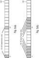
- Fig. 9 illustrates an example of the PMI feedback for a rank-1 transmission assuming three codebooks for the precoder matrix.
- the first PMI part as shown in Fig 9 contains at least the basis subset indictors for the Doppler-frequency, delay and beam vectors selected from the Doppler, delay and beam codebooks.
- the UE may quantize the coefficients using a codebook approach.
- the second PMI part as shown in Fig 9 contains at least the quantized combining coefficients to which the Doppler, delay and beam basis subset indicators are associated with.
- the two-component PMIs are reported to the gNB or any other network entity
- the UE reports the CSI report using the physical uplink shared channel (PUSCH) to the gNB or any other network entity.
- PUSCH physical uplink shared channel
- the following codebook based construction is described for the case of a precoding matrix configured with Doppler-frequency, delay and beam codebooks. Note that other cases such as a precoding matrix configured with only a Doppler-frequency codebook, or a precoding matrix configured with a Doppler-frequency codebook and delay codebook are straightforward, and therefore not explicitly discussed in the
- the precoder matrix information is used to calculate a multi-user precoding matrix which is applied to the transmission signals to adapt the transmission parameters to the current multi-user channel conditions.
- the above Doppler-based precoder matrix definitions also facilitate the prediction of precoder matrices for future time instances. In this way, the number of CSI reports may be drastically reduced and feedback overhead is saved.
- the predicted precoding matrices may be used in predictive multi-user scheduling algorithms that attempt to optimize, for example, the throughput for all users by using the knowledge of current and future precoder matrices of the users.
- the combining coefficients ⁇ are normalized per layer with respect to a strongest combining coefficient such that the amplitude of the strongest normalized combining coefficient is 1 (or any other reference value). Since the normalized strongest coefficient is always given by the same value, the UE is configured not to report the strongest coefficient (bit values for the amplitude and phase of the quantized coefficient) and to indicate per layer the strongest coefficient by a strongest coefficient indicator in the CSI report.
- the strongest coefficient indicator associated with r-th layer is given by ⁇ log 2 ( N Z r ) ⁇ or max r ⁇ log 2 NZ r ⁇ or ⁇ log 2 ( K ( r ) ) ⁇ or max r ⁇ log 2 K r ⁇ bit indicator and the CSI part 1 contains the selected number of non-zero combining coefficients (NNZCC) for each of the RI layers.
- NZ r represents the number of non-zero components indicated for the r-th layer in CSI part 1
- K ( r ) represents the maximum number of non-zero components configured per layer.
- the UE may be configured to predict a CQI value for time-instant/slot " n + K ", where n denotes the current time-instant/slot, and K denotes the relative time difference with respect to the current time-instant/slot n .
- the UE uses in a first step a high resolution parameter estimation algorithm, such as RIMAX (see reference [5]), to estimate parameters of a channel model directly from the multi-dimensional channel matrix/tensor .
- a high resolution parameter estimation algorithm such as RIMAX (see reference [5])
- the time-variant channel model impulse response may be defined by a number of channel taps, where each channel tap is parameterized with a channel gain, Doppler-frequency shift and a delay.
- the coefficients of H ( t,w ) may also be calculated directly in a non-parameterized form from the MIMO channel tensor by using a linear block-filtering approach such as least squares or minimum-mean-squared-error (MMSE) filtering (see references [6] and [7]).
- MMSE minimum-mean-squared-error
- the channel predictor is formed by a weighted sum of the MIMO channel matrix/tensor .
- the UE uses the parameterized precoded MIMO channel model response to calculate a CQI value for a future time instant n + K, i.e., the CQI( n + K ) is expressed as a function of H prec ( n + K, w ).
- the K predicted CQI values may be used to calculate differential predicted CQI values by reducing the K predicted CQI values by the "average" CQI value.
- the predicted single CQI value, or predicted K CQI values, or predicted K differential CQI values is/are reported to the gNB.
- a communication device for providing a channel state information, CSI, feedback in a wireless communication system, wherein the communication device receives a CSI-RS resource configuration including a higher layer (e.g., RRC) parameter, e.g., referred to as CSI-RS-BurstDuration, indicating a time-domain-repetition of the reference signals, e.g., in terms of a number of consecutive slots the reference signals are repeated in.
- the communication device determines the CSI feedback based on the repeated reference signals and reports the determined CSI feedback.
- the corresponding PDSCH signals [ y ( t ,3000) ( i ) ⁇ y ( t ,3000+ P -1) ( i )] transmitted on antenna ports [3000,3000 + P - 1] have a ratio of, energy per resource element, EPRE, to CSI-RS EPRE equal to the ratio given in Subclause 4.1 of TS 38.214 (see reference [2]).
- the precoder matrix is kept constant over time until it is updated by a reported PMI.
- the approach described above takes into account the channel variations by updating the precoder matrix continuously over time without instantaneous PMI reporting.
- the wireless communication system may include a terrestrial network, or a non-terrestrial network, or networks or segments of networks using as a receiver an airborne vehicle or a spaceborne vehicle, or a combination thereof.
- the UE may comprise one or more of a mobile or stationary terminal, an loT device, a ground based vehicle, an aerial vehicle, a drone, a building, or any other item or device provided with network connectivity enabling the item/device to communicate using the wireless communication system, like a sensor or actuator.
- the base station may comprise one or more of a macro cell base station, or a small cell base station, or a spaceborne vehicle, like a satellite or a space, or an airborne vehicle, like a unmanned aircraft system (UAS), e.g., a tethered UAS, a lighter than air UAS (LTA), a heavier than air UAS (HTA) and a high altitude UAS platforms (HAPs), or any transmission/reception point (TRP) enabling an item or a device provided with network connectivity to communicate using the wireless communication system.
- UAS unmanned aircraft system
- LTA lighter than air UAS
- HTA heavier than air UAS
- HAPs high altitude UAS platforms
- TRP transmission/reception point
- the embodiments of the present invention have been described above with reference to a communication system employing a rank 1 or layer 1 communication. However, the present invention is not limited to such embodiments and may also be implemented in a communication system employing a higher rank or layer communication.
- the feedback includes the delays per layer and the complex precoder coefficients per layer.
- a communication is between a transmitter, like a gNB or a UE, and a receiver, like a UE and a gNB.
- the invention is not limited to such a communication, rather, the above-described principles may equally be applied for a device-to-device communication, like a D2D, V2V, V2X communication.
- the communication is over a sidelink between the respective devices.
- the transmitter is a first UE and the receiver is a second UE communicating using the sidelink resources.
- the embodiments of the present invention have been described above with reference to a communication system in which the transmitter is a base station serving a user equipment, and the communication device or receiver is the user equipment served by the base station.
- the invention is not limited to such a communication, rather, the above-described principles may equally be applied for a device-to-device communication, like a D2D, V2V, V2X communication.
- the communication is over a sidelink between the respective devices.
- the transmitter is a first UE and the receiver is a second UE communicating using the sidelink resources.
- the present invention is not limited to precoding between a UE and a base station, but is equally applicable to, e.g., sidelink-based precoding for UE to UE communications.
- a block or a device corresponds to a method step or a feature of a method step.
- aspects described in the context of a method step also represent a description of a corresponding block or item or feature of a corresponding apparatus.
- Various elements and features of the present invention may be implemented in hardware using analog and/or digital circuits, in software, through the execution of instructions by one or more general purpose or special-purpose processors, or as a combination of hardware and software.
- embodiments of the present invention may be implemented in the environment of a computer system or another processing system.
- Fig. 12 illustrates an example of a computer system 350.
- the units or modules as well as the steps of the methods performed by these units may execute on one or more computer systems 350.
- the computer system 350 includes one or more processors 352, like a special purpose or a general purpose digital signal processor.
- the processor 352 is connected to a communication infrastructure 354, like a bus or a network.
- the computer system 350 includes a main memory 356, e.g., a random access memory (RAM), and a secondary memory 358, e.g., a hard disk drive and/or a removable storage drive.
- the secondary memory 358 may allow computer programs or other instructions to be loaded into the computer system 350.
- the computer system 350 may further include a communications interface 360 to allow software and data to be transferred between computer system 350 and external devices.
- the communication may be in the from electronic, electromagnetic, optical, or other signals capable of being handled by a communications interface.
- the communication may use a wire or a cable, fiber optics, a phone line, a cellular phone link, an RF link and other communications channels 362.
- computer program medium and “computer readable medium” are used to generally refer to tangible storage media such as removable storage units or a hard disk installed in a hard disk drive.
- These computer program products are means for providing software to the computer system 350.
- the computer programs also referred to as computer control logic, are stored in main memory 356 and/or secondary memory 358. Computer programs may also be received via the communications interface 360.
- the computer program when executed, enables the computer system 350 to implement the present invention.
- the computer program when executed, enables processor 352 to implement the processes of the present invention, such as any of the methods described herein. Accordingly, such a computer program may represent a controller of the computer system 350.
- the software may be stored in a computer program product and loaded into computer system 350 using a removable storage drive, an interface, like communications interface 360.
- the implementation in hardware or in software may be performed using a digital storage medium, for example cloud storage, a floppy disk, a DVD, a Blue-Ray, a CD, a ROM, a PROM, an EPROM, an EEPROM or a FLASH memory, having electronically readable control signals stored thereon, which cooperate (or are capable of cooperating) with a programmable computer system such that the respective method is performed. Therefore, the digital storage medium may be computer readable.
- a digital storage medium for example cloud storage, a floppy disk, a DVD, a Blue-Ray, a CD, a ROM, a PROM, an EPROM, an EEPROM or a FLASH memory, having electronically readable control signals stored thereon, which cooperate (or are capable of cooperating) with a programmable computer system such that the respective method is performed. Therefore, the digital storage medium may be computer readable.
- Some embodiments according to the invention comprise a data carrier having electronically readable control signals, which are capable of cooperating with a programmable computer system, such that one of the methods described herein is performed.
- embodiments of the present invention may be implemented as a computer program product with a program code, the program code being operative for performing one of the methods when the computer program product runs on a computer.
- the program code may for example be stored on a machine readable carrier.
- inventions comprise the computer program for performing one of the methods described herein, stored on a machine readable carrier.
- an embodiment of the inventive method is, therefore, a computer program having a program code for performing one of the methods described herein, when the computer program runs on a computer.
- a further embodiment of the inventive methods is, therefore, a data carrier (or a digital storage medium, or a computer-readable medium) comprising, recorded thereon, the computer program for performing one of the methods described herein.
- a further embodiment of the inventive method is, therefore, a data stream or a sequence of signals representing the computer program for performing one of the methods described herein. The data stream or the sequence of signals may for example be configured to be transferred via a data communication connection, for example via the Internet.
- a further embodiment comprises a processing means, for example a computer, or a programmable logic device, configured to or adapted to perform one of the methods described herein.
- a further embodiment comprises a computer having installed thereon the computer program for performing one of the methods described herein.
- a programmable logic device for example a field programmable gate array
- a field programmable gate array may cooperate with a microprocessor in order to perform one of the methods described herein.
- the methods are preferably performed by any hardware apparatus.
Landscapes
- Engineering & Computer Science (AREA)
- Computer Networks & Wireless Communication (AREA)
- Signal Processing (AREA)
- Physics & Mathematics (AREA)
- Mathematical Physics (AREA)
- Mobile Radio Communication Systems (AREA)
Priority Applications (3)
| Application Number | Priority Date | Filing Date | Title |
|---|---|---|---|
| EP19191582.6A EP3780410A1 (de) | 2019-08-13 | 2019-08-13 | Csi-bericht- und -codebuchstruktur zur doppler-codebuch-basierten vorcodierung in einem drahtloskommunikationssystem |
| PCT/EP2020/072226 WO2021028331A1 (en) | 2019-08-13 | 2020-08-07 | Csi reporting and codebook structure for doppler codebook-based precoding in a wireless communications system |
| EP20750287.3A EP4014340A1 (de) | 2019-08-13 | 2020-08-07 | Csi-bericht- und -codebuchstruktur zur doppler-codebuch-basierten vorcodierung in einem drahtloskommunikationssystem |
Applications Claiming Priority (1)
| Application Number | Priority Date | Filing Date | Title |
|---|---|---|---|
| EP19191582.6A EP3780410A1 (de) | 2019-08-13 | 2019-08-13 | Csi-bericht- und -codebuchstruktur zur doppler-codebuch-basierten vorcodierung in einem drahtloskommunikationssystem |
Publications (1)
| Publication Number | Publication Date |
|---|---|
| EP3780410A1 true EP3780410A1 (de) | 2021-02-17 |
Family
ID=67658721
Family Applications (2)
| Application Number | Title | Priority Date | Filing Date |
|---|---|---|---|
| EP19191582.6A Withdrawn EP3780410A1 (de) | 2019-08-13 | 2019-08-13 | Csi-bericht- und -codebuchstruktur zur doppler-codebuch-basierten vorcodierung in einem drahtloskommunikationssystem |
| EP20750287.3A Pending EP4014340A1 (de) | 2019-08-13 | 2020-08-07 | Csi-bericht- und -codebuchstruktur zur doppler-codebuch-basierten vorcodierung in einem drahtloskommunikationssystem |
Family Applications After (1)
| Application Number | Title | Priority Date | Filing Date |
|---|---|---|---|
| EP20750287.3A Pending EP4014340A1 (de) | 2019-08-13 | 2020-08-07 | Csi-bericht- und -codebuchstruktur zur doppler-codebuch-basierten vorcodierung in einem drahtloskommunikationssystem |
Country Status (2)
| Country | Link |
|---|---|
| EP (2) | EP3780410A1 (de) |
| WO (1) | WO2021028331A1 (de) |
Cited By (8)
| Publication number | Priority date | Publication date | Assignee | Title |
|---|---|---|---|---|
| US11483044B2 (en) * | 2019-09-20 | 2022-10-25 | Qualcomm Incorporated | Channel state information reporting prioritization |
| WO2023033698A1 (en) * | 2021-08-30 | 2023-03-09 | Telefonaktiebolaget Lm Ericsson (Publ) | Systems and methods for channel state information reporting for channel prediction |
| WO2023037316A1 (en) * | 2021-09-13 | 2023-03-16 | Nokia Technologies Oy | Demodulation reference signal assisted channel state information feedback scheme |
| WO2023202770A1 (en) * | 2022-04-21 | 2023-10-26 | Nokia Technologies Oy | A method and apparatus for csi compression in time domain |
| WO2023204970A1 (en) * | 2022-04-18 | 2023-10-26 | Qualcomm Incorporated | Method and apparatus for per-path doppler reporting based on tracking reference signal |
| WO2023175025A3 (en) * | 2022-03-15 | 2023-12-21 | Fraunhofer Gesellschaft zur Förderung der angewandten Forschung e.V. | Csi reporting for 5g nr systems |
| WO2024036242A1 (en) * | 2022-08-11 | 2024-02-15 | Apple Inc. | Codebook design for csi enhancement to exploit time domain properties |
| WO2024063682A3 (en) * | 2022-09-23 | 2024-05-02 | Telefonaktiebolaget Lm Ericsson (Publ) | Indication of non-zero coefficients in rel-18 type ii codebook for high velocity |
Families Citing this family (3)
| Publication number | Priority date | Publication date | Assignee | Title |
|---|---|---|---|---|
| WO2023141861A1 (en) * | 2022-01-27 | 2023-08-03 | Qualcomm Incorporated | Temporal and spatial precoding of downlink signals |
| US20230318793A1 (en) * | 2022-03-30 | 2023-10-05 | Samsung Electronics Co., Ltd. | Method and apparatus for configuring semi-persistent csi-rs resources |
| CN117014100A (zh) * | 2022-04-29 | 2023-11-07 | 北京紫光展锐通信技术有限公司 | 通信方法及通信装置 |
Citations (1)
| Publication number | Priority date | Publication date | Assignee | Title |
|---|---|---|---|---|
| WO2018052255A1 (en) | 2016-09-14 | 2018-03-22 | Samsung Electronics Co., Ltd. | Method and apparatus to enable channel compression in advanced wireless communication systems |
-
2019
- 2019-08-13 EP EP19191582.6A patent/EP3780410A1/de not_active Withdrawn
-
2020
- 2020-08-07 EP EP20750287.3A patent/EP4014340A1/de active Pending
- 2020-08-07 WO PCT/EP2020/072226 patent/WO2021028331A1/en unknown
Patent Citations (1)
| Publication number | Priority date | Publication date | Assignee | Title |
|---|---|---|---|---|
| WO2018052255A1 (en) | 2016-09-14 | 2018-03-22 | Samsung Electronics Co., Ltd. | Method and apparatus to enable channel compression in advanced wireless communication systems |
Non-Patent Citations (12)
| Title |
|---|
| "3rd Generation Partnership Project; Technical Specification Group Radio Access Network; NR; Physical channels and modulation (Release 15", 3GPP TS 38.211, March 2018 (2018-03-01) |
| "3rd Generation Partnership Project; Technical Specification Group Radio Access Network; NR; Physical layer procedures for data (Release 15", 3GPP TS 38.214, March 2018 (2018-03-01) |
| "3rd Generation Partnership Project; Technical Specification Group Radio Access Network; NR; Radio Resource Control (RRC); Protocol specification (Release 15", 3GPP TS 38.331, March 2018 (2018-03-01) |
| FRAUNHOFER IIS ET AL: "Enhancements on Type-II CSI reporting", vol. RAN WG1, no. Spokane, USA; 20181112 - 20181116, 11 November 2018 (2018-11-11), XP051555112, Retrieved from the Internet <URL:http://www.3gpp.org/ftp/Meetings%5F3GPP%5FSYNC/RAN1/Docs/R1%2D1813130%2Ezip> [retrieved on 20181111] * |
| FRAUNHOFER IIS ET AL: "Further Enhancements on Type-II CSI Reporting: Doppler-domain Approach", vol. RAN WG1, no. Xi'an, China; 20190408 - 20190412, 7 April 2019 (2019-04-07), XP051699548, Retrieved from the Internet <URL:http://www.3gpp.org/ftp/Meetings%5F3GPP%5FSYNC/RAN1/Docs/R1%2D1904219%2Ezip> [retrieved on 20190407] * |
| I. BARHUMIG. LEUSM. MOONEN: "Optimal training design for MIMO OFDM systems in mobile wireless channels", IEEE TRANS. SIGNAL PROCESS, vol. 51, no. 6, June 2003 (2003-06-01), pages 1615 - 1624 |
| K. MANOLAKISS. JAECKELV. JUGNICKELV. BRAUN: "Channel Prediction by Doppler-Delay Analysis and Benefits for Base Station Cooperation", 77TH IEEE VEHICULAR TECHNOLOGY CONFERENCE, June 2013 (2013-06-01) |
| NOKIA ET AL: "Remaining details on CSI reporting for Type II and Type I codebook", vol. RAN WG1, no. Prague, CZ; 20171009 - 20171013, 8 October 2017 (2017-10-08), XP051341692, Retrieved from the Internet <URL:http://www.3gpp.org/ftp/Meetings_3GPP_SYNC/RAN1/Docs/> [retrieved on 20171008] * |
| P. HOEHERS. KAISERP. ROBERTSON: "Two-dimensional pilot-symbol-aided channel estimation by Wiener filtering", PROC. IEEE ICASSP-97, April 1997 (1997-04-01), pages 1845 - 1848 |
| QUALCOMM INCORPORATED: "Remaining details of feedback for TM9", 3GPP DRAFT; R1-110919 REMAINING DETAILS OF FEEDBACK FOR TM9, 3RD GENERATION PARTNERSHIP PROJECT (3GPP), MOBILE COMPETENCE CENTRE ; 650, ROUTE DES LUCIOLES ; F-06921 SOPHIA-ANTIPOLIS CEDEX ; FRANCE, vol. RAN WG1, no. Taipei, Taiwan; 20110121 - 20110125, 15 February 2011 (2011-02-15), XP050599146 * |
| R. S. THOMAM. LANDMANNA. RICHTER: "RIMAX-A maximum likelihood framework for parameter estimation in multidimensional channel sounding", PROCEEDINGS OF THE INTERNATIONAL SYMPOSIUM ON ANTENNAS AND PROPAGATION (ISAP'04, 2004 |
| SAMSUNG: "Enhancements on MIMO for NR", vol. TSG RAN, no. Newport Beach, USA; 20190603 - 20190607, 2 June 2019 (2019-06-02), XP051747395, Retrieved from the Internet <URL:http://www.3gpp.org/ftp/Meetings%5F3GPP%5FSYNC/RAN/Docs/RP%2D191187%2Ezip> [retrieved on 20190602] * |
Cited By (8)
| Publication number | Priority date | Publication date | Assignee | Title |
|---|---|---|---|---|
| US11483044B2 (en) * | 2019-09-20 | 2022-10-25 | Qualcomm Incorporated | Channel state information reporting prioritization |
| WO2023033698A1 (en) * | 2021-08-30 | 2023-03-09 | Telefonaktiebolaget Lm Ericsson (Publ) | Systems and methods for channel state information reporting for channel prediction |
| WO2023037316A1 (en) * | 2021-09-13 | 2023-03-16 | Nokia Technologies Oy | Demodulation reference signal assisted channel state information feedback scheme |
| WO2023175025A3 (en) * | 2022-03-15 | 2023-12-21 | Fraunhofer Gesellschaft zur Förderung der angewandten Forschung e.V. | Csi reporting for 5g nr systems |
| WO2023204970A1 (en) * | 2022-04-18 | 2023-10-26 | Qualcomm Incorporated | Method and apparatus for per-path doppler reporting based on tracking reference signal |
| WO2023202770A1 (en) * | 2022-04-21 | 2023-10-26 | Nokia Technologies Oy | A method and apparatus for csi compression in time domain |
| WO2024036242A1 (en) * | 2022-08-11 | 2024-02-15 | Apple Inc. | Codebook design for csi enhancement to exploit time domain properties |
| WO2024063682A3 (en) * | 2022-09-23 | 2024-05-02 | Telefonaktiebolaget Lm Ericsson (Publ) | Indication of non-zero coefficients in rel-18 type ii codebook for high velocity |
Also Published As
| Publication number | Publication date |
|---|---|
| WO2021028331A1 (en) | 2021-02-18 |
| EP4014340A1 (de) | 2022-06-22 |
Similar Documents
| Publication | Publication Date | Title |
|---|---|---|
| US11616551B2 (en) | Doppler-delay codebook-based precoding and CSI reporting wireless communications systems | |
| US11996910B2 (en) | Doppler codebook-based precoding and CSI reporting for wireless communications systems | |
| US11595089B2 (en) | CSI reporting and codebook structure for doppler-delay codebook-based precoding in a wireless communications system | |
| US11876589B2 (en) | Explicit channel information feedback based on high-order PCA decomposition or PCA composition | |
| EP3780410A1 (de) | Csi-bericht- und -codebuchstruktur zur doppler-codebuch-basierten vorcodierung in einem drahtloskommunikationssystem | |
| US20220385344A1 (en) | Csi reporting based on linear combination port-selection codebook | |
| EP3780411A1 (de) | Vorcodierermatrixanzeige und codebuchstruktur zur vorcodierung für frequenzselektive mimo-kanäle | |
| US20230361842A1 (en) | Improving precoding | |
| EP3855635A1 (de) | Csi-bericht auf basis eines port-codebuchs mit linearer kombination | |
| EP4002713A1 (de) | Csi-meldung auf basis eines linearen kombinations-codebuchs | |
| WO2024079100A1 (en) | Enhanced type-ii doppler-based csi reporting for 5g nr systems | |
| CN117957789A (zh) | 用于在无线通信网络中联合传输的csi报告的方法和装置 |
Legal Events
| Date | Code | Title | Description |
|---|---|---|---|
| PUAI | Public reference made under article 153(3) epc to a published international application that has entered the european phase |
Free format text: ORIGINAL CODE: 0009012 |
|
| STAA | Information on the status of an ep patent application or granted ep patent |
Free format text: STATUS: THE APPLICATION HAS BEEN PUBLISHED |
|
| AK | Designated contracting states |
Kind code of ref document: A1 Designated state(s): AL AT BE BG CH CY CZ DE DK EE ES FI FR GB GR HR HU IE IS IT LI LT LU LV MC MK MT NL NO PL PT RO RS SE SI SK SM TR |
|
| AX | Request for extension of the european patent |
Extension state: BA ME |
|
| STAA | Information on the status of an ep patent application or granted ep patent |
Free format text: STATUS: THE APPLICATION IS DEEMED TO BE WITHDRAWN |
|
| 18D | Application deemed to be withdrawn |
Effective date: 20210818 |