EP3855579A1 - Steckverbinder, insbesondere push-pull-verbinder, zum verbinden mit einer steckverbinderbuchse, steckverbindersystem und verwendung eines steckverbinders - Google Patents
Steckverbinder, insbesondere push-pull-verbinder, zum verbinden mit einer steckverbinderbuchse, steckverbindersystem und verwendung eines steckverbinders Download PDFInfo
- Publication number
- EP3855579A1 EP3855579A1 EP21152679.3A EP21152679A EP3855579A1 EP 3855579 A1 EP3855579 A1 EP 3855579A1 EP 21152679 A EP21152679 A EP 21152679A EP 3855579 A1 EP3855579 A1 EP 3855579A1
- Authority
- EP
- European Patent Office
- Prior art keywords
- connector
- housing element
- socket
- side locking
- plug
- Prior art date
- Legal status (The legal status is an assumption and is not a legal conclusion. Google has not performed a legal analysis and makes no representation as to the accuracy of the status listed.)
- Granted
Links
Images



Classifications
-
- H—ELECTRICITY
- H01—ELECTRIC ELEMENTS
- H01R—ELECTRICALLY-CONDUCTIVE CONNECTIONS; STRUCTURAL ASSOCIATIONS OF A PLURALITY OF MUTUALLY-INSULATED ELECTRICAL CONNECTING ELEMENTS; COUPLING DEVICES; CURRENT COLLECTORS
- H01R13/00—Details of coupling devices of the kinds covered by groups H01R12/70 or H01R24/00 - H01R33/00
- H01R13/62—Means for facilitating engagement or disengagement of coupling parts or for holding them in engagement
- H01R13/629—Additional means for facilitating engagement or disengagement of coupling parts, e.g. aligning or guiding means, levers, gas pressure electrical locking indicators, manufacturing tolerances
- H01R13/633—Additional means for facilitating engagement or disengagement of coupling parts, e.g. aligning or guiding means, levers, gas pressure electrical locking indicators, manufacturing tolerances for disengagement only
-
- H—ELECTRICITY
- H01—ELECTRIC ELEMENTS
- H01R—ELECTRICALLY-CONDUCTIVE CONNECTIONS; STRUCTURAL ASSOCIATIONS OF A PLURALITY OF MUTUALLY-INSULATED ELECTRICAL CONNECTING ELEMENTS; COUPLING DEVICES; CURRENT COLLECTORS
- H01R13/00—Details of coupling devices of the kinds covered by groups H01R12/70 or H01R24/00 - H01R33/00
- H01R13/62—Means for facilitating engagement or disengagement of coupling parts or for holding them in engagement
- H01R13/627—Snap or like fastening
- H01R13/6275—Latching arms not integral with the housing
-
- H—ELECTRICITY
- H01—ELECTRIC ELEMENTS
- H01R—ELECTRICALLY-CONDUCTIVE CONNECTIONS; STRUCTURAL ASSOCIATIONS OF A PLURALITY OF MUTUALLY-INSULATED ELECTRICAL CONNECTING ELEMENTS; COUPLING DEVICES; CURRENT COLLECTORS
- H01R13/00—Details of coupling devices of the kinds covered by groups H01R12/70 or H01R24/00 - H01R33/00
- H01R13/648—Protective earth or shield arrangements on coupling devices, e.g. anti-static shielding
- H01R13/658—High frequency shielding arrangements, e.g. against EMI [Electro-Magnetic Interference] or EMP [Electro-Magnetic Pulse]
- H01R13/6581—Shield structure
- H01R13/6582—Shield structure with resilient means for engaging mating connector
- H01R13/6583—Shield structure with resilient means for engaging mating connector with separate conductive resilient members between mating shield members
-
- H—ELECTRICITY
- H01—ELECTRIC ELEMENTS
- H01R—ELECTRICALLY-CONDUCTIVE CONNECTIONS; STRUCTURAL ASSOCIATIONS OF A PLURALITY OF MUTUALLY-INSULATED ELECTRICAL CONNECTING ELEMENTS; COUPLING DEVICES; CURRENT COLLECTORS
- H01R24/00—Two-part coupling devices, or either of their cooperating parts, characterised by their overall structure
- H01R24/60—Contacts spaced along planar side wall transverse to longitudinal axis of engagement
- H01R24/62—Sliding engagements with one side only, e.g. modular jack coupling devices
- H01R24/64—Sliding engagements with one side only, e.g. modular jack coupling devices for high frequency, e.g. RJ 45
Definitions
- the invention relates to a connector, in particular a push-pull connector, for connecting to a connector socket, a connector system and a use of a connector.
- Plug connectors in particular push-pull connectors, are designed to accommodate a plug attached to a cable.
- a plug connector socket that can be connected to the plug connector generally has a plug socket into which the plug is inserted for connection.
- the connector In order to connect the connector to the connector socket, the connector is pushed into the connector socket along an insertion direction, where it locks with the connector socket. Furthermore, the lock between the connector and the connector socket can be released by pulling the connector against the insertion direction.
- the connector and the connector socket can be connected easily and securely, that an established connection between the connector and the connector socket cannot be unintentionally released, and that the established connection can be released easily and without great effort.
- the locked state advantageously prevents the plug connector from being unintentionally released from the plug connector socket, for example by inadvertently touching the plug connector or the cable received by the plug connector. This ensures a secure connection between the plug arranged in the plug connector and a plug socket arranged in the plug connector socket. Furthermore, by moving the second housing element counter to the insertion direction, the plug connector can be detached from the plug connector socket in a simple manner, whereby the connection between plug and plug socket is separated.
- the first housing element can in particular be designed as an internal housing element which at least in sections surrounds the plug and the cable connected to the plug along the insertion direction.
- the term “insertion direction” is to be understood as the direction in which the connector is inserted into the connector socket to establish a connection or the direction in which the connector is inserted into the socket for connection.
- the first housing element can be designed to have a specific type of plug, for example an RJ45 plug, a USB plug or coax plug, in such a way that the first housing element surrounds the plug at least in sections along the insertion direction.
- the second housing element can in particular be designed as an external housing element and surround the first housing element at least in sections along the insertion direction.
- the plug connector can be connected to the plug connector socket or the plug connector can be detached from the plug connector socket by means of an operating action of the external housing element carried out by a user.
- the plug connector can be connected to the plug connector socket by moving the second housing element in the direction of the insertion direction.
- a locking position can be assumed by a relative movement of the second housing element in the direction of the insertion with respect to the first housing element, in which the connector-side locking element can be locked with the connector-socket-side locking element.
- the locking between the connector-side locking element and the connector-socket-side locking element can be released by a relative movement of the second housing element against the insertion direction with respect to the first housing element, so that the connector can be released or removed from the connector socket.
- the first housing element can in particular have a first access opening and a second access opening, which are arranged opposite one another.
- the first access opening and the second access opening run essentially perpendicular to the insertion direction or essentially perpendicular to a longitudinal axis of the connector or the longitudinal axis of the first housing element.
- imaginary surfaces each formed by the first access opening and the second access opening extend essentially perpendicular to the insertion direction or perpendicular to the longitudinal axis of the plug connector or longitudinal axis of the first housing element.
- first access opening and the second access opening can be spaced from one another and connected to one another by a wall of the first housing element.
- the first access opening and the second access opening as well as the wall of the first housing element thus form a receiving space in which the plug and the cable connected to the plug can be received at least in sections along the insertion direction.
- the wall of the first housing element surrounds, in particular, at least sections of the plug along the insertion direction and the cable connected to the plug at least sections of the plug.
- the first access opening forms an end of the first housing element lying in the insertion direction and the second access opening forms an end of the first housing element lying opposite to the insertion direction.
- the plug connected to the cable can be inserted in the insertion direction through the second access opening into the first housing element and that the plug protrudes at least in sections through the first access opening in the insertion direction from the first housing element.
- the second housing element can have a first access opening and a second access opening, which are arranged opposite one another.
- the first access opening and the second access opening run essentially perpendicular to the insertion direction or essentially perpendicular to a longitudinal axis of the connector or the longitudinal axis of the second housing element.
- imaginary surfaces each formed by the first access opening and the second access opening extend essentially perpendicular to the insertion direction or perpendicular to the longitudinal axis of the connector or the longitudinal axis of the second housing element.
- first access opening and the second access opening of the second housing element can be spaced from one another and connected to one another by a wall of the first housing element.
- the first access opening and the second access opening as well as the wall of the second housing element thus form a receiving space for receiving the first housing element at least in sections.
- the second housing element is formed shorter along the insertion direction than the first housing element.
- the at least one connector-side locking element can preferably be arranged at least in sections in a cavity located between the first housing element and the second housing element. Furthermore, when connecting the connector to the connector socket, a connection section of the connector socket can be inserted into the cavity, so that the connection section of the connector socket protrudes at least in sections into the cavity in the locked state, thereby ensuring a stable and secure connection of the connector and the connector socket. Furthermore, the at least one connector-side locking element can be arranged on an outwardly directed surface of the wall of the first housing element, the outwardly directed surface essentially facing the second housing element. Furthermore, the connector-side locking element in the locked state can be arranged at least in sections between the connecting section of the connector socket and the second housing element.
- the at least one connector-side locking element can preferably be designed to engage behind the connector-socket-side locking element in the locked state.
- By engaging behind the locking element on the connector socket side a particularly stable connection between the connector and the connector socket can be ensured. In particular, an unintentional separation of the connector from the connector socket can be prevented.
- the at least one connector-side locking element can preferably be moved outward at least in sections by moving the second housing element into the unlocking position in order to release a lock with the connector socket-side locking element.
- a relative movement of the second housing element against the insertion direction with respect to the first Housing element, the lock between the connector-side locking element and the connector socket-side locking element are canceled.
- the at least one connector-side locking element can preferably be designed to be resilient and, in the unlocked position, exert a resetting force directed in the direction of the cable. That is, the connector-side locking element strives to assume the locking position independently.
- the connector-side locking element is released by a corresponding relative movement of the second housing element with respect to the first housing element starting from the unlocking position in the plug-in direction, so that it shifts by itself in the direction of the longitudinal axis of the connector.
- the second housing element does not press the connector-side locking element in the direction of the longitudinal axis of the connector in order to assume the locking position in which the connector-side locking element engages behind the connector-socket-side locking element.
- the at least one connector-side locking element can preferably contact the second housing element in such a way that, in the unlocked position, a force acting in the direction of the insertion direction is exerted on the second housing element.
- the second housing element can advantageously be subjected to a relative movement with respect to the first housing element in order to move the second housing element from the unlocked position in the insertion direction.
- the connector-side locking element can thus advantageously assume the locking position independently. Furthermore, an unintentional relative movement of the second housing element with respect to the first housing element against the insertion direction can be essentially prevented.
- the at least one connector-side locking element can preferably have a fastening section and a locking section connected to the fastening section, the at least one connector-side locking element being attached by means of the fastening section can be fastened to the first housing element, and wherein the locking section extends in the direction of the insertion direction and is arranged at least in sections between the fastening section and the second housing element.
- the first housing element can have at least one receiving element on the outside or on the outwardly directed surface of the wall of the first housing element, into which the fastening section of the connector-side locking element can be inserted.
- the fastening section can be inserted into the receiving element in the insertion direction.
- the fastening section can be locked to the receiving element, so that the connector-side locking element can be securely connected to the first housing element.
- the plug connector can thus advantageously have a modular structure, which ensures simple assembly of the plug connector.
- the receiving element can be designed in the form of a slot and the connector-side locking element can be designed as a stamped thin sheet metal part, the fastening section of the connector-side locking element being insertable into the slot-shaped receiving element in the insertion direction.
- the locking section of the connector-side locking element can extend in the insertion direction starting from an end of the fastening section lying in the opposite direction to the insertion direction.
- the connector-side locking element can have a curved section which connects the fastening section and the locking section to one another. Furthermore, due to the curved section, the locking section can freely spring outward and inward relative to the longitudinal axis of the connector.
- the locking section can have at one end in the insertion direction a contacting surface positioned opposite the insertion direction or longitudinal axis of the connector, which at least in sections rests against a support section formed by a passage opening provided in the second housing element.
- the passage opening can essentially be formed parallel to the insertion direction.
- the connector-side locking element or the locking section of the connector-side locking element can be moved outward or away from the longitudinal axis of the connector due to the relative movement of the second housing element in relation to the first housing element against the insertion direction, whereby the locking between the connector-side locking element and the connector-socket-side locking element can be canceled.
- the aforementioned relative movement of the second housing element can enable the connector-side locking element to be guided through the passage opening at least in sections.
- a force in the direction of the insertion direction can be exerted on the second housing element via the contacting surface when the latter is in the unlocking position.
- the second housing element can thus be pressed in the plug-in direction by the locking element on the connector side.
- the support section can preferably be guided along the contacting surface counter to the insertion direction.
- the contacting surface preferably points inwards or in the direction of the longitudinal axis of the connector, but does not run parallel to the longitudinal axis of the connector.
- the distance between the contacting surface and the longitudinal axis of the connector increases with the course of the contacting surface in the direction of the insertion direction. Due to the course of the contacting surface, the relative movement of the second housing element with respect to the first housing element against the insertion direction causes an outward pushing, i.e. away from the longitudinal axis of the connector, of the contacting section or the locking section of the connector-side locking element.
- the at least one connector-side locking element can preferably have an opening which is designed to engage behind the connector socket-side locking element, wherein the connector socket-side locking element is preferably designed as a nose.
- the locking section can have the opening.
- the plug connector and the plug connector socket can be unlocked and / or locked by a linear movement of the second housing element relative to the first housing element along the insertion direction.
- at least one guide element can be formed between the first housing element and the second housing element, which guide element supports a guided movement of the second housing element along the insertion direction.
- the at least one guide element can furthermore be designed to prevent the second housing element from rotating relative to the first housing element about the longitudinal axis of the connector.
- the at least one guide element can for example have a guide nose which is formed on the first housing element.
- the guide nose is arranged on the outwardly directed surface of the wall of the first housing element and extends essentially in the insertion direction.
- the at least one guide element can have a guide groove which is arranged on the second housing element in such a way that the guide nose is guided in the guide groove.
- the guide groove is arranged on an inwardly directed surface of the wall of the second housing element, the inwardly directed surface being opposite the outwardly directed surface.
- the guide groove and the guide nose can also be interchanged, so that the second housing element has the guide nose and the first housing element has the guide groove.
- the at least one guide element can advantageously be designed to limit a movement of the second housing element in the insertion direction with respect to the first housing element. It can thus be prevented that the second housing element is separated from the first housing element by moving in the insertion direction.
- the guide groove on a in opposite to the direction of insertion, have a stop on which the guide nose strikes the end.
- the at least one guide element and the at least one connector-side locking element are arranged, looking in the insertion direction, offset by essentially 90 ° with respect to the longitudinal axis of the connector.
- the connector has at least two locking elements on the connector side, each locking element on the connector side being designed to lock with a corresponding locking element on the connector socket side.
- the plug connector has at least two guide elements which are each arranged between the first housing element and the second housing element.
- the connector can have exactly two locking elements on the connector side, each locking element on the connector side being designed to lock with a corresponding locking element on the connector socket side.
- the two connector-side locking elements can be arranged opposite one another on the first housing element with respect to the longitudinal axis of the connector or the longitudinal axis of the first housing element.
- this embodiment can have exactly two guide elements (as described above).
- the two guide elements can be arranged opposite between the first housing element and the second housing element with respect to the longitudinal axis of the connector or the longitudinal axis of the first housing element.
- the at least one connector-side can preferably do this
- the locking element and the first housing element can be designed to provide an electrically conductive connection between the second housing element and a shield of a cable which is at least partially surrounded by the first housing element, and / or to provide an electrically conductive connection between the connector socket and the shield.
- the first housing element, the second housing element and the plug connector socket can be made from a metallic alloy and designed, for example, as a zinc die-cast component.
- the shield on the plug side can thus be electrically connected to the shield on the plug socket side, as a result of which particularly good shielding is ensured by the plug connector and plug connector socket.
- the plug connector can preferably have a cable guide that is flexible at least in regions, which surrounds the cable at least in sections, the cable guide being adaptable to the diameter of the cable.
- the cable guide can protect the cable arranged in the connector from kinks and mechanical stresses.
- the cable guide surrounds the cable at least in sections along the insertion direction. Furthermore, the cable guide can be connectable to the first housing element. In particular, the cable guide can be arranged at an end of the first housing element that is opposite to the insertion direction.
- the plug connector can preferably be designed to be connected to the plug connector socket in a rotationally secure manner. This can advantageously prevent incorrect connection of the plug and socket.
- the wall of the second housing element can have a first and a second wall section, which are arranged essentially parallel and opposite one another with respect to the longitudinal axis of the plug connector.
- the wall of the second housing element can have a third and fourth wall section, the third section being essentially perpendicular to the first wall portion and the second wall portion is formed.
- the fourth wall section can be arranged opposite the third wall section in relation to the longitudinal axis of the connector and can be curved or arched.
- the connecting section can have a corresponding configuration so that the plug connector can be arranged on the plug connector socket so that it cannot rotate.
- the connector socket can furthermore have a plate-shaped base element which is arranged essentially perpendicular to the insertion direction. Furthermore, the base element can have a receiving opening which is designed to receive, at least in sections, a plug socket into which the plug arranged in the plug connector can be inserted. Furthermore, the connector socket can have a wall-shaped connecting section, which is designed, in the connected state of the plug connector and plug connector socket, to protrude at least in sections into a cavity located between the first housing element and the second housing element. Furthermore, the connecting section can have the at least one locking element on the plug connector socket side.
- the connector can be developed as described above.
- the plug connector has a plug which can be connected to a plug socket arranged in the plug connector socket by connecting the plug connector to the plug connector socket.
- the connector and the connector socket can be designed as described above.
- Figures 1 and 2 show a plug connector 10 which at least in sections surrounds a plug 12 arranged in the plug connector 10 and at least in sections a cable 14 connected to the plug 12.
- the connector 10 is designed to be used with one as shown in FIG Figures 4 and 5 Connector socket 16 shown to be connected.
- the plug connector 10 is moved in the direction of the insertion direction E in order to connect the plug connector 10 to the plug connector socket 16.
- the plug connector 10 has a first housing element 18 which is arranged on the inside of the plug connector 10. The first housing element 18 surrounds the plug 12 and the cable 14 at least in sections along the insertion direction E.
- FIGS Figures 1 and 2 a second housing element 20 of the plug connector 10, which is arranged on the outside and surrounds the first housing element 18 at least in sections along the insertion direction.
- the plug connector 10 is designed so that the second housing element 20 can be moved in relation to the first housing element 18 along the insertion direction E or along the longitudinal axis L of the plug connector 10.
- the longitudinal axis L lies essentially parallel to the insertion direction E.
- the plug connector 10 has at least one locking element 22 on the plug connector side.
- the connector 10 has exactly two connector-side locking elements 22 which are arranged at least in sections between the first housing element 18 and the second housing element 20.
- the connector-side locking elements 22 are designed in particular to be connected with corresponding locking elements 24 (see FIG Figures 4 and 5 ), which are arranged on the connector socket 16 (see Figures 4 and 5 ) to be locked when the connector 10 is connected to the connector socket 16.
- the first housing element 18 has a first access opening 26 and a second access opening 28.
- the first access opening 26 and the second access opening 28 are arranged opposite one another and spaced apart from one another and are essentially perpendicular to the longitudinal axis L of the connector 10. Furthermore, the first access opening 26 and the second access opening 28 are connected to one another by a wall 30 of the first housing element 18.
- the first access opening 26 forms an end of the first housing element 18 lying in the insertion direction E and the second access opening 28 forms an end of the first housing element 18 lying opposite the insertion direction E.
- the wall 30 of the first housing element 18 is thus designed for this purpose to surround the plug 12 and the cable 14 at least in sections along the insertion direction E.
- the second housing element 20 has a first access opening 32 and a second access opening 34, which are arranged opposite one another and spaced apart from one another. Furthermore, the first access opening 32 and the second access opening 34 are arranged essentially perpendicular to the insertion direction E and to the longitudinal axis L of the plug connector 10. Furthermore, the second housing element 20 has a wall 36 which is arranged between the first access opening 32 and the second access opening 34 and extends at least in sections along the insertion direction E or longitudinal axis L of the plug connector 10. The wall 36 of the second housing element 20 surrounds the first housing element 18 at least in sections.
- At least one receiving element 40 is provided on an outwardly pointing surface 38 of the wall 30 of the first housing element 18, which is provided for fastening the connector-side locking element 22.
- the receiving element 40 is designed to receive a fastening section 42 of the connector-side locking element 22.
- they show Figures 3 and 4th exactly two receiving elements 40, which are arranged on the surface 30, wherein exactly one connector-side locking element 22 can be fastened to each receiving element 40.
- the receiving elements 40 are in relation to the longitudinal axis L of the connector 10 arranged opposite one another.
- the receiving element 40 is designed, in particular, in the shape of a slot, with the fastening section 42 being insertable into the receiving element 40 in the insertion direction in order to fasten the connector-side locking element 22 to the receiving element 40. Furthermore, the receiving element 40 and the fastening section 42 are designed to be lockable with one another, so that the connector-side locking element 22 can be securely fastened to the first housing element 18. Opposite to the insertion direction E, the fastening section 42 is followed by a section 44 which is bent by approximately 180 ° and which connects the fastening section 42 to a locking section 46 of the connector-side locking element 22. Starting from the curved section 44, the locking section 46 extends essentially in the direction of the insertion direction E. The locking section 46 is designed in particular to be locked with the locking element 24 on the connector socket side (see FIG Figure 5 ).
- the locking section 46 contacts the second housing element 20 in such a way that a relative movement of the second housing element 20 with respect to the first housing element 18 counter to the insertion direction E moves the locking section 46 outward, i.e. away from the longitudinal axis L of the connector 10 .
- a relative movement of the second housing element 20 counter to the insertion direction E locking of the connector-side locking element 22 or the locking section 46 with the connector-socket-side locking element 24 is canceled.
- the second housing element 20 and, connected to it the locking section 46 can be moved into an unlocking position.
- the connector-side locking element 22 is resilient, so that when the second housing element 20 moves relative to the first housing element 18 in the insertion direction E, the connector-side locking element 22 or the locking section 46 automatically assumes a locking position in which the connector-side locking element 22 or the connecting section 46 with the connector socket side Locking element 24 is lockable.
- the locking section 46 has a locking opening 47 which enables the locking section 46 to engage behind the locking element 24 on the connector socket side in the locked state.
- the connector socket-side locking element 24 is designed, for example, as a projection or nose.
- the locking section 46 has, at an end lying in the insertion direction E, a contacting surface 48 which is inclined with respect to the insertion direction E or longitudinal axis L, which at least in sections rests against a support section 50 formed by a through-opening 50 provided in the second housing element 20.
- the contacting surface 48 is positioned in relation to the longitudinal axis L in such a way that the distance between the contacting surface 48 and the longitudinal axis L increases in the insertion direction E.
- a relative movement of the second housing element 20 with respect to the first housing element 18 counter to the insertion direction E thus leads to an outward displacement of the locking section 46, as a result of which the locking element 24 on the connector socket side can be removed from reaching behind.
- the resilience of the connector-side locking element 22 enables a force acting in the insertion direction E to be exerted on the second housing element 20, so that the second housing element 20 can be moved or displaced in the direction of the insertion direction E by the connector-side locking element 22.
- the two receiving elements 40 are arranged opposite one another with respect to the longitudinal axis L.
- the two connector-side locking elements 22 are arranged opposite one another with respect to the longitudinal axis L of the connector 10.
- the locking section 46 has at least one inwardly directed contacting element 54, which is designed to contact the connector socket 16 in the connected state of the connector 10 and the connector socket 16.
- the Connector-side locking element 22 has at least one outwardly directed contacting element 56 which is designed to contact the inside of the second housing element 20.
- the first housing element 18 is designed to make electrical contact with a shielding of the plug 12 or of the cable 14.
- the connector socket 16 is designed to make electrical contact with a shield of the connector socket arranged in the connector socket 16 or a cable (not shown) connected to the connector socket.
- the connector-side locking element 22 is designed to electrically connect the first housing element 18 to the second housing element 20, so that when the connector 10 and connector socket 16 are connected, the connector-side shield and the connector-socket-side shield are electrically connected to one another.
- At least one guide element 60 is arranged between the first housing element 18 and the second housing element 20.
- the guide element 60 is designed to support a linear movement of the second housing element 20 in relation to the first housing element 18 along the insertion direction E.
- the guide element 60 consists of a guide nose 62 which is arranged on the outside of the first housing element 18 and which is arranged on the outwardly facing surface 38 of the wall 30 of the first housing element 18.
- the second housing element 20 has on an inside or on the inwardly facing surface of the wall 36 of the second housing element 20 a guide groove 64 in which the guide nose 62 can be guided.
- Rotation of the second housing element 20 relative to the first housing element 18 in relation to the longitudinal axis L can be prevented by the guide element 60.
- the ones in the Figures 6-8 The embodiment shown has in particular exactly two guide elements 60 which are arranged opposite one another with respect to the longitudinal axis L. Furthermore, the guide groove 64 has a stop which limits a relative movement of the second housing element 20 with respect to the first housing element 18 in the direction of the insertion direction E.
- the guide elements 60 and the connector-side locking elements 22 looking in the plug-in direction E are arranged offset by 90 ° with respect to the longitudinal axis L.
- Figure 4 shows an example of a connector socket 16, which consists of a plate-shaped base element 70, which is arranged essentially perpendicular to the insertion direction E. Furthermore, the base element 70 has an opening 72 in which a connector-side socket can be arranged at least in sections.
- the connector socket 16 has a wall which is designed as a connecting section 72.
- the connecting section 72 at least partially surrounds the longitudinal axis L of the connector socket 16.
- the connecting section 72 is designed to protrude into a cavity 74 located between the first housing element 18 and the second housing element 20 when the connector 10 and the connector socket 16 are connected.
- the connecting section 72 has the plug connector socket-side locking elements 24 on the outside, which are arranged opposite one another with respect to the longitudinal axis L.
- the second housing element 20 looking in the insertion direction E, has a shape which prevents the connector 10 from rotating with respect to the connector socket 16.
- the second housing element 20 has a first housing section 76 and a second housing section 78, which are arranged opposite one another in relation to the longitudinal axis L and extend essentially parallel to the insertion direction E.
- the second housing element 20 has a third housing section 80 which is arranged perpendicular to the first housing section 76 and to the second housing section 78.
- the third housing section 80 likewise extends parallel to the insertion direction E.
- the second housing element 20 has a fourth housing section 82, which is arranged opposite the third housing section 80 in relation to the longitudinal axis L.
- the fourth housing section 82 has a curved or curved surface when viewed in the insertion direction E. curved shape. Furthermore, the connecting section 72 is shaped in accordance with the shape of the second housing element 20, so that the second housing element 20 can be connected to the plug connector socket 16 in a rotationally secure manner.
- FIG. 5 a connected state of the plug connector 10 to the plug connector socket 16.
- the connecting section 72 protrudes at least in sections into the cavity between the first housing element 18 and the second housing element 20.
- Figure 5 how the locking section 46 of the connector socket-side locking element 24 engages behind.
- the connector 10 can have an at least regionally flexible cable guide 58 which surrounds the cable 14 at least in sections, the cable guide 58 being adaptable to the diameter of the cable 14.
- the cable guide 58 can advantageously protect the cable 14 arranged in the plug connector 10 from kinks and mechanical stresses.
- the cable guide 58 surrounds the cable 14 at least in sections along the insertion direction E.
- the cable guide 58 can be connected to the first housing element 18.
- the cable guide 58 can be arranged at an end of the first housing element 18 lying opposite to the insertion direction E.
Landscapes
- Details Of Connecting Devices For Male And Female Coupling (AREA)
Abstract
Description
- Die Erfindung betrifft einen Steckverbinder, insbesondere einen Push-Pull-Verbinder, zum Verbinden mit einer Steckverbinderbuchse, ein Steckverbindersystem und eine Verwendung eines Steckverbinders.
- Steckerverbinder, insbesondere Push-Pull-Verbinder, sind dazu ausgelegt, einen an einem Kabel befestigten Stecker aufzunehmen. Eine mit dem Steckverbinder verbindbare Steckverbinderbuchse weist in der Regel eine Steckerbuchse auf, in welche der Stecker zum Verbinden eingeführt wird. Um den Steckverbinder mit der Steckverbinderbuchse zu verbinden, wird der Steckverbinder in die Steckverbinderbuchse entlang einer Einsteckrichtung gedrückt, wo dieser mit der Steckverbinderbuchse verriegelt. Ferner kann durch Ziehen des Steckverbinders entgegen der Einsteckrichtung die Verriegelung zwischen Steckverbinder und Steckverbinderbuchse gelöst werden.
- Dabei ist es wünschenswert, dass sich der Steckverbinder und die Steckverbinderbuchse einfach und sicher verbinden lassen, eine eingegangene Verbindung zwischen Steckverbinder und Steckverbinderbuchse nicht unbeabsichtigt gelöst werden kann, und die eingegangene Verbindung einfach und ohne großen Kraftaufwand gelöst werden kann.
- Diese Aufgabe wird durch die Gegenstände der unabhängigen Ansprüche gelöst. Bevorzugte Ausführungsformen sind in den abhängigen Ansprüchen definiert.
- Ein Aspekt bezieht sich auf einen Steckverbinder, insbesondere einen Push-Pull-Verbinder, zum Verbinden mit einer Steckverbinderbuchse, aufweisend:
- ein erstes Gehäuseelement, welches dazu ausgebildet ist, einen mit einem Kabel verbundenen Stecker zumindest teilweise entlang einer Einsteckrichtung des Steckverbinders in die Steckverbinderbuchse zu umgeben;
- mindestens ein an dem ersten Gehäuseelement angeordnetes steckverbinderseitiges Verriegelungselement zum Verriegeln des Steckverbinders mit der Steckverbinderbuchse, wobei das mindestens eine steckverbinderseitige Verriegelungselement dazu ausgebildet ist, in einem verriegelten Zustand des Steckverbinders mit der Steckverbinderbuchse, mit einem steckverbinderbuchsenseitigen Verriegelungselement zu verriegeln; und
- ein zweites Gehäuseelement, welches zumindest teilweise das erste Gehäuseelement und das steckverbinderseitige Verriegelungselement umgibt, wobei das zweite Gehäuseelement in Bezug auf das erste Gehäuseelement entlang der Einsteckrichtung bewegbar ist; und
- Vorteilhafterweise verhindert der verriegelte Zustand, dass der Steckerverbinder unbeabsichtigt von der Steckverbinderbuchse gelöst werden kann, beispielsweise durch unbeabsichtigtes Berühren des Steckverbinders oder das von dem Steckverbinder aufgenommene Kabel. Somit wird eine sichere Verbindung zwischen dem in dem Steckverbinder angeordneten Stecker und einer in der Steckverbinderbuchse angeordneten Steckerbuchse gewährleistet. Ferner kann durch das Bewegen des zweiten Gehäuseelements entgegen der Einsteckrichtung, der Steckverbinder auf einfache Weise von der Steckverbinderbuchse gelöst werden, wodurch die Verbindung zwischen Stecker und Steckerbuchse getrennt wird.
- Das erste Gehäuseelement kann insbesondere als innenliegendes Gehäuseelement ausgebildet sein, welches zumindest abschnittsweise den Stecker und das mit dem Stecker verbundene Kabel entlang der Einsteckrichtung umgibt. Im Rahmen der vorliegenden Offenbarung ist unter dem Begriff "Einsteckrichtung" die Richtung zu verstehen, in welche der Steckverbinder in die Steckverbinderbuchse zum Eingehen einer Verbindung eingesteckt wird bzw. die Richtung, in welche der Stecker in die Steckerbuchse zum Verbinden eingesteckt wird. Insbesondere kann das erste Gehäuseelement dazu ausgebildet sein, einen spezifischen Steckertyp, beispielsweise einen RJ45-Stecker, einen USB-Stecker oder Koax-Stecker, aufzunehmen, und zwar derart, dass das erste Gehäuseelement den Stecker zumindest abschnittsweise entlang der Einsteckrichtung umgibt.
- Das zweite Gehäuseelement kann insbesondere als außenliegendes Gehäuseelement ausgebildet sein und das erste Gehäuseelement zumindest abschnittsweise entlang der Einsteckrichtung umgeben. Mittels einer, durch einen Nutzer getätigten, Bedienungshandlung des außenliegenden Gehäuseelements kann der Steckverbinder mit der Steckverbinderbuchse verbunden werden bzw. kann der Steckverbinder von der Steckverbinderbuchse gelöst werden. Insbesondere ist vorgesehen, dass durch ein Bewegen des zweiten Gehäuseelements in Richtung der Einsteckrichtung, der Steckverbinder mit der Steckverbinderbuchse verbunden werden kann. Insbesondere kann durch eine Relativbewegung des zweiten Gehäuseelements in Richtung der Einsteckrichtung gegenüber dem ersten Gehäuseelement eine Verriegelungsposition eingenommen werden, in der das steckverbinderseitige Verriegelungselement mit dem steckverbinderbuchsenseitigen Verriegelungselement verriegelbar ist.
- Ferner kann durch eine Relativbewegung des zweiten Gehäuseelements entgegen der Einsteckrichtung gegenüber dem ersten Gehäuseelement die Verriegelung zwischen dem steckverbinderseitigen Verriegelungselement und dem steckverbinderbuchsenseitigen Verriegelungselement gelöst werden, so dass der Steckverbinder von der Steckverbinderbuchse lösbar bzw. entfernbar ist.
- Das erste Gehäuseelement kann insbesondere eine erste Zugangsöffnung und eine zweite Zugangsöffnung aufweisen, welche gegenüberliegend angeordnet sind. Insbesondere verlaufen die erste Zugangsöffnung und die zweite Zugangsöffnung im Wesentlichen senkrecht zur Einsteckrichtung bzw. im Wesentlichen senkrecht zu einer Längsachse des Steckverbinders bzw. Längsachse des ersten Gehäuseelements. Mit anderen Worten, jeweils durch die erste Zugangsöffnung und die zweite Zugangsöffnung gebildete imaginäre Flächen erstrecken sich im Wesentlichen senkrecht zur Einsteckrichtung bzw. senkrecht zur Längsachse des Steckverbinders bzw. Längsachse des ersten Gehäuseelements.
- Ferner können die erste Zugangsöffnung und die zweite Zugangsöffnung voneinander beabstandet sein und durch eine Wand des ersten Gehäuseelements miteinander verbunden sein. Die erste Zugangsöffnung und die zweite Zugangsöffnung sowie die Wand des ersten Gehäuseelements bilden somit einen Aufnahmeraum, in welchem der Stecker und das mit dem Stecker verbundene Kabel zumindest abschnittsweise entlang der Einsteckrichtung aufgenommen werden kann. Die Wand des ersten Gehäuseelements umgibt insbesondere zumindest abschnittsweise den Stecker entlang der Einsteckrichtung und den mit dem Stecker verbundene Kabel zumindest abschnittsweise entlang der Einsteckrichtung. Ferner bildet die erste Zugangsöffnung ein in Einsteckrichtung liegendes Ende des ersten Gehäuseelements und die zweite Zugangsöffnung bildet ein entgegen der Einsteckrichtung liegendes Ende des ersten Gehäuseelements. Insbesondere ist vorgesehen, dass der mit dem Kabel verbundenen Stecker in Einsteckrichtung durch die zweite Zugangsöffnung in das erste Gehäuseelement einführbar ist und dass der Stecker zumindest abschnittsweise durch die erste Zugangsöffnung in Einsteckrichtung aus dem ersten Gehäuseelement hinausragt.
- Des Weiteren kann das zweite Gehäuseelement eine erste Zugangsöffnung und eine zweite Zugangsöffnung aufweisen, welche gegenüberliegend angeordnet sind. Insbesondere verlaufen die erste Zugangsöffnung und die zweite Zugangsöffnung im Wesentlichen senkrecht zur Einsteckrichtung bzw. im Wesentlichen senkrecht zu einer Längsachse des Steckverbinders bzw. Längsachse des zweiten Gehäuseelements. Mit anderen Worten, jeweils durch die erste Zugangsöffnung und die zweite Zugangsöffnung gebildete imaginäre Flächen erstrecken sich im Wesentlichen senkrecht zur Einsteckrichtung bzw. senkrecht zur Längsachse des Steckverbinders bzw. Längsachse des zweiten Gehäuseelements.
- Ferner können die erste Zugangsöffnung und die zweite Zugangsöffnung des zweiten Gehäuseelements voneinander beabstandet sein und durch eine Wand des ersten Gehäuseelements miteinander verbunden sein. Die erste Zugangsöffnung und die zweite Zugangsöffnung sowie die Wand des zweiten Gehäuseelements bilden somit einen Aufnahmeraum zum zumindest abschnittsweisen Aufnehmen des ersten Gehäuseelements. Insbesondere kann vorgesehen sein, dass das zweite Gehäuseelement entlang der Einsteckrichtung kürzer ausgebildet ist als das erste Gehäuseelement.
- Bevorzugt kann das mindestens eine steckverbinderseitige Verriegelungselement zumindest abschnittsweise in einem zwischen dem ersten Gehäuseelement und dem zweiten Gehäuseelement befindlichen Hohlraum angeordnet sein. Ferner kann beim Verbinden des Steckverbinders mit der Steckverbinderbuchse ein Verbindungsabschnitt der Steckverbinderbuchse in den Hohlraum eingeführt werden, so dass der Verbindungsabschnitt der Steckverbinderbuchse im verriegelten Zustand zumindest abschnittsweise in den Hohlraum hineinragt, wodurch eine stabile und sichere Bindung von Steckverbinder und Steckverbinderbuchse gewährleistet ist. Des Weiteren kann das mindestens eine steckverbinderseitige Verriegelungselement an einer nach außen gerichteten Fläche der Wand des ersten Gehäuseelements angeordnet sein, wobei die nach außen gerichtete Fläche im Wesentlichem dem zweiten Gehäuseelement zugewandt ist. Ferner kann das steckverbinderseitige Verriegelungselement im verriegelten Zustand zumindest Abschnittsweise zwischen dem Verbindungsabschnitt der Steckverbinderbuchse und dem zweiten Gehäuseelement angeordnet sein.
- Bevorzugt kann das mindestens eine steckverbinderseitige Verriegelungselement dazu ausgebildet sein, in dem verriegelten Zustand, das steckverbinderbuchsenseitige Verriegelungselement zu hintergreifen. Durch das Hintergreifen des steckverbinderbuchsenseitigen Verriegelungselements kann eine besonders stabile Verbindung zwischen Steckverbinder und Steckverbinderbuchse gewährleistet werden. Insbesondere kann ein unbeabsichtigtes Trennen des Steckverbinders von der Steckverbinderbuchse verhindert werden.
- Bevorzugt kann das mindestens eine steckverbinderseitige Verriegelungselement durch das Bewegen des zweiten Gehäuseelements in die Entriegelungsposition zumindest abschnittsweise nach außen bewegt werden, um eine Verriegelung mit dem steckverbinderbuchsenseitigen Verriegelungselement zu lösen. Vorteilhafterweise kann somit durch eine Relativbewegung des zweiten Gehäuseelements entgegen der Einsteckrichtung in Bezug auf das erste Gehäuseelement die Verriegelung zwischen dem steckverbinderseitigen Verriegelungselement und dem steckverbinderbuchsenseitigen Verriegelungselement aufgehoben werden.
- Bevorzugt kann das mindestens eine steckverbinderseitige Verriegelungselement rückstellfähig ausgebildet sein und in der Entriegelungsposition eine in Richtung Kabel gerichtete Rückstellkraft ausüben. D.h. das steckverbinderseitige Verriegelungselement ist bestrebt, selbstständig die Verriegelungsposition einzunehmen. Insbesondere wird durch eine entsprechende Relativbewegung des zweiten Gehäuseelements in Bezug auf das erste Gehäuseelement von der Entriegelungsposition ausgehend in Einsteckrichtung, das steckverbinderseitige Verriegelungselement freigegeben, so dass es sich von selbst in Richtung der Längsachse des Steckverbinders verlagert. Mit anderen Worten, das zweite Gehäuseelement drückt das steckverbinderseitige Verriegelungselement nicht in Richtung zur Längsachs des Steckverbinders, um die Verriegelungsposition einzunehmen, in welcher das steckverbinderseitige Verriegelungselement das steckverbinderbuchsenseitige Verriegelungselement hintergreift.
- Bevorzugt kann das mindestens eine steckverbinderseitige Verriegelungselement das zweite Gehäuseelement derart kontaktieren, dass in der Entriegelungsposition auf das zweite Gehäuseelement eine, in Richtung der Einsteckrichtung wirkende, Kraft ausgeübt wird. Vorteilhafterweise kann dadurch das zweite Gehäuseelement einer Relativbewegung gegenüber dem ersten Gehäuseelement ausgesetzt werden, um das zweite Gehäuseelement von der Entriegelungsposition in Einsteckrichtung zu bewegen. Vorteilhafterweise kann somit das steckverbinderseitige Verriegelungselement eigenständig die Verriegelungsposition einnehmen. Ferner kann dadurch eine unbeabsichtigte Relativbewegung des zweiten Gehäuseelements gegenüber dem ersten Gehäuseelement entgegen der Einsteckrichtung im Wesentlichen verhindert werden.
- Bevorzugt kann das mindestens eine steckverbinderseitige Verriegelungselement einen Befestigungsabschnitt und einen mit dem Befestigungsabschnitt verbundenen Verriegelungsabschnitt aufweisen, wobei das mindestens eine steckverbinderseitige Verriegelungselement mittels des Befestigungsabschnitts an dem ersten Gehäuseelement befestigbar ist, und wobei der Verriegelungsabschnitt sich in Richtung der Einsteckrichtung erstreckt und zumindest abschnittsweise zwischen dem Befestigungsabschnitt und dem zweiten Gehäuseelement angeordnet ist.
- Ferner kann das erste Gehäuseelement an der Außenseite bzw. an der nach außen gerichteten Fläche der Wand des ersten Gehäuseelements zumindest ein Aufnahmeelement aufweisen, in welches der Befestigungsabschnitt des steckverbinderseitigen Verriegelungselements einführbar ist. Insbesondere ist der Befestigungsabschnitt in das Aufnahmeelement in Einsteckrichtung einführbar. Ferner kann vorgesehen sein, dass der Befestigungsabschnitt mit dem Aufnahmeelement verriegelbar ist, so dass das steckverbinderseitige Verriegelungselement sicher mit dem ersten Gehäuseelement verbindbar ist. Vorteilhafterweise kann somit der Steckverbinder modular aufgebaut werden was eine einfache Montage des Steckverbinder gewährleistet. Beispielsweise kann das Aufnahmeelement schlitzförmig ausgebildet sein und das steckverbinderseitige Verriegelungselement kann als gestanztes Dünnblechteil ausgebildet sein, wobei der Befestigungsabschnitt des steckverbinderseitigen Verriegelungselements in das schlitzförmige Aufnahmeelement in Einsteckrichtung einführbar ist.
- Ferner kann sich der Verriegelungsabschnitt des steckverbinderseitigen Verriegelungselements ausgehend von einem, in entgegen der Einsteckrichtung liegenden, Ende des Befestigungsabschnitts in Einsteckrichtung erstrecken. Dazu kann das steckverbinderseitige Verriegelungselement einen gebogenen Abschnitt aufweisen, welcher den Befestigungsabschnitt und den Verriegelungsabschnitt miteinander verbindet. Ferner kann durch den gebogenen Abschnitt der Verriegelungsabschnitt frei nach außen und nach innen bezogen auf die Längsachse des Steckverbinders federn.
- Bevorzugt kann der Verriegelungsabschnitt an einem, in Einsteckrichtung liegenden, Ende eine gegenüber der Einsteckrichtung bzw. Längsachse des Steckverbinders angestellte Kontaktierungsfläche aufweisen, welche zumindest abschnittsweise an einem durch eine in dem zweiten Gehäuseelement vorgesehene Durchtrittsöffnung gebildeten Auflageabschnitt anliegt. Die Durchtrittsöffnung kann im Wesentlichen parallel zur Einsteckrichtung ausgebildet sein. Durch das Anliegen der angestellten Kontaktierungsfläche an dem Auflageabschnitt, kann durch die Relativbewegung des zweiten Gehäuseelements in Bezug auf das erste Gehäuseelement entgegen der Einsteckrichtung, das steckverbinderseitige Verriegelungselement bzw. der Verriegelungsabschnitt des steckverbinderseitige Verriegelungselement nach außen bzw. Weg von der Längsachse des Steckverbinders bewegt werden, wodurch die Verriegelung zwischen steckverbinderseitigen Verriegelungselement und steckverbinderbuchsenseitigen Verriegelungselement aufgehoben werden kann. Ferner kann die zuvor genannte Relativbewegung des zweiten Gehäuseelements ermöglichen, dass das steckverbinderseitige Verriegelungselement zumindest abschnittsweise durch die Durchtrittsöffnung hindurchgeführt wird.
- Ferner kann über die Kontaktierungsfläche eine Kraft in Richtung der Einsteckrichtung auf das zweite Gehäuseelement ausgeübt werden, wenn dieses sich in der Entriegelungsposition befindet. Vorteilhafterweise kann somit das zweite Gehäuseelement durch das steckverbinderseitige Verriegelungselement in Einsteckrichtung gedrückt werden.
- Bevorzugt kann durch Bewegen des zweiten Gehäuseelements in die Entriegelungsposition, der Auflageabschnitt entgegen der Einsteckrichtung an der Kontaktierungsfläche entlanggeführt werden. Die Kontaktierungsfläche weist bevorzugt nach innen bzw. in Richtung der Längsachse des Steckverbinders, verläuft allerdings nicht parallel zur Längsachse des Steckverbinders. Insbesondere vergrößert sich der Abstand zwischen Kontaktierungsfläche und Längsachse des Steckverbinders mit dem Verlauf der Kontaktierungsfläche in Richtung der Einsteckrichtung. Durch den Verlauf der Kontaktierungsfläche bewirkt die Relativbewegung des zweiten Gehäuseelements gegenüber dem ersten Gehäuseelement entgegen der Einsteckrichtung, ein nach außen gerichtetes Drücken, d.h. von der Längsachse des Steckverbinders weg, des Kontaktierungsabschnitts bzw. des Verriegelungsabschnitts des steckverbinderseitigen Verriegelungselements.
- Bevorzugt kann das mindestens eine steckverbinderseitige Verriegelungselement eine Öffnung aufweisen, die dazu ausgebildet ist, das steckverbinderbuchsenseitige Verriegelungselement zu hintergreifen, wobei das steckverbinderbuchsenseitige Verriegelungselement bevorzugt als Nase ausgebildet ist. Insbesondere kann der Verriegelungsabschnitt die Öffnung aufweisen.
- Bevorzugt können der Steckverbinder und die Steckverbinderbuchse durch eine Linearbewegung des zweiten Gehäuseelements gegenüber dem ersten Gehäuseelement entlang der Einsteckrichtung entriegelbar und/oder verriegelbar sein. Ferner kann zwischen dem ersten Gehäuseelement und dem zweiten Gehäuseelement mindestens ein Führungselement ausgebildet sein, welches eine geführte Bewegung des zweiten Gehäuseelements entlang der Einsteckrichtung unterstützt. Das mindestens eine Führungselement kann des Weiteren dazu ausgebildet sein, ein Drehen des zweiten Gehäuseelements gegenüber dem ersten Gehäuseelement um die Längsachse des Steckverbinders herum zu verhindern.
- Das mindestens eine Führungselemente kann beispielsweise eine Führungsnase aufweisen, welche an dem ersten Gehäuseelement ausgebildet ist. Insbesondere ist die Führungsnase auf der nach außen gerichteten Fläche der Wand des ersten Gehäuseelements angeordnet und erstreckt sich im Wesentlichen in Einsteckrichtung. Ferner kann das mindestens eine Führungselement eine Führungsnut aufweisen, welche an dem zweiten Gehäuseelement derart angeordnet ist, dass die Führungsnase in der Führungsnut geführt wird. Insbesondere ist die Führungsnut auf einer nach innen gerichteten Fläche der Wand des zweiten Gehäuseelements angeordnet, wobei die nach innen gerichtete Fläche der nach außen gerichteten Fläche gegenüberliegt. Alternativ können die Führungsnut und die Führungsnase auch vertauscht sein, so dass das zweite Gehäuseelement die Führungsnase aufweist und das erste Gehäuseelement die Führungsnut.
- Vorteilhafterweise kann das mindestens eine Führungselemente dazu ausgebildet sein, eine Bewegung des zweiten Gehäuseelements in Einsteckrichtung gegenüber dem ersten Gehäuseelement zu begrenzen. Somit kann verhindert werden, dass das zweite Gehäuseelement durch ein Bewegen in Einsteckrichtung von dem ersten Gehäuseelement getrennt wird. Beispielsweise kann die Führungsnut an einem, in entgegen der Einsteckrichtung liegenden, Ende einen Anschlag aufweisen, an welchem die Führungsnase anschlägt.
- Vorzugsweise sind das mindestens eine Führungselement und das mindestens eine steckverbinderseitige Verriegelungselement in Einsteckrichtung blickend um im Wesentlichen 90° versetzt, bezogen auf die Längsachse des Steckverbinders, angeordnet.
- Vorzugsweise ist vorgesehen, dass der Steckverbinder mindestsens zwei steckverbinderseitige Verriegelungselemente aufweist, wobei jedes steckverbinderseitige Verriegelungselement dazu ausgebildet ist mit einem entsprechenden steckverbinderbuchsenseitigen Verriegelungselement zu verriegeln.
- Vorzugsweise ist vorgesehen, dass der Steckverbinder mindestens zwei Führungselemente aufweist, welche jeweils zwischen dem ersten Gehäuseelement und dem zweiten Gehäuseelement angeordnet sind.
- In einer besonders bevorzugten Ausführungsform kann der Steckverbinder genau zwei steckverbinderseitige Verriegelungselemente aufweisen, wobei jedes steckverbinderseitige Verriegelungselement dazu ausgebildet ist mit einem entsprechenden steckverbinderbuchsenseitigen Verriegelungselement zu verriegeln. Die zwei steckverbinderseitigen Verriegelungselemente können in Bezug auf die Längsachse des Steckverbinders bzw. Längsachse des ersten Gehäuseelements gegenüberliegend an dem ersten Gehäuseelement angeordnet sein.
- Ferner kann diese Ausführungsform genau zwei Führungselemente (wie oben beschrieben) aufweisen, Die zwei Führungselemente können in Bezug auf die Längsachse des Steckverbinders bzw. Längsachse des ersten Gehäuseelements gegenüberliegend zwischen dem ersten Gehäuseelement und dem zweiten Gehäuseelement angeordnet sein.
- Bevorzugt können das mindestens eine steckverbinderseitige Verriegelungselement und das erste Gehäuseelement dazu ausgebildet sein, eine elektrisch leitende Verbindung zwischen dem zweiten Gehäuseelement und einer Abschirmung eines Kabels, welches zumindest abschnittsweise von dem ersten Gehäuseelement umgeben ist, bereitzustellen, und/oder eine elektrisch leitende Verbindung zwischen der Steckverbinderbuchse und der Abschirmung bereitzustellen. Insbesondere können das erste Gehäuseelement, das zweite Gehäuseelement und die Steckverbinderbuchse aus einer metallischen Legierung gefertigt sein und beispielsweise als Zinkdruckguss Bauteil ausgebildet sein.
- Vorteilhafterweise kann somit die steckerseitige Abschirmung mit der steckerbuchsenseitigen Abschirmung elektrisch verbunden werden, wodurch eine besonders gute Abschirmung durch den Steckverbinder und Steckverbinderbuchse gewährleistet ist.
- Bevorzugt kann der Steckverbinder eine zumindest bereichsweise flexible Kabelführung aufweisen, welche das Kabel zumindest abschnittsweise umgibt, wobei die Kabelführung an den Durchmesser des Kabels anpassbar ist. Vorteihafterweise kann die Kabelführung das im Steckverbinder angeordnete Kabel vor Knicken und mechanischen Beanspruchungen schützen.
- Die Kabelführung umgibt das Kabel dabei zumindest abschnittsweise entlang der Einsteckrichtung. Ferner kann die Kabelführung mit dem ersten Gehäuseelement verbindbar sein. Insbesondere kann die Kabelführung an einem, entgegen der Einsteckrichtung liegenden, Ende des ersten Gehäuseelements angeordnet sein.
- Vorzugsweise kann der Steckverbinder dazu ausgebildet sein, verdrehsicher mit der Steckverbinderbuchse verbunden zu werden. Dadurch kann vorteilhaft ein falsches Verbinden von Stecker und Steckerbuchse verhindert werden.
- Beispielsweise kann die Wand des zweiten Gehäuseelements einen ersten und einen zweiten Wandabschnitt aufweisen, die in Bezug auf die Längsachse des Steckverbinders im Wesentlichen parallel gegenüberliegend angeordnet sind. Ferner kann die Wand des zweiten Gehäuseelements einen dritten und vierten Wandabschnitt aufweisen, wobei der dritte Abschnitt im Wesentlichen senkrecht zu dem ersten Wandabschnitt und zu dem zweiten Wandabschnitt ausgebildet ist. Der vierte Wandabschnitt kann in Bezug auf die Längsachse des Steckverbinders dem dritten Wandabschnitt gegenüberliegend angeordnet sein und gekrümmt bzw. gewölbt ausgebildet sein. Ferner kann der Verbindungsabschnitt eine entsprechende Ausgestaltung aufweisen, so dass der Steckverbinder auf der Steckverbinderbuchse verdrehsicher angeordnet werden kann.
- Ein weiterer Aspekt betrifft ein Steckverbindersystem aufweisend:
- eine Steckverbinderbuchse; und
- einen Steckverbinder, insbesondere einen Push-Pull-Verbinder, zum Verbinden mit der Steckverbinderbuchse, aufweisend:
- ein erstes Gehäuseelement, welches dazu ausgebildet ist, einen mit einem Kabel verbundenen Stecker zumindest teilweise entlang einer Einsteckrichtung des Steckverbinders in die Steckverbinderbuchse zu umgeben;
- mindestens ein, an dem ersten Gehäuseelement angeordnetes, steckverbinderseitiges Verriegelungselement zum Verriegeln des Steckverbinders mit der Steckverbinderbuchse, wobei das mindestens eine steckverbinderseitige Verriegelungselement dazu ausgebildet ist, in einem verriegelten Zustand des Steckverbinders mit der Steckverbinderbuchse, mit einem steckverbinderbuchsenseitigen Verriegelungselement zu verriegeln; und
- ein zweites Gehäuseelement, welches zumindest teilweise das erste Gehäuseelement und das steckverbinderseitige Verriegelungselement umgibt, wobei das zweite Gehäuseelement in Bezug auf das erste Gehäuseelement entlang der Einsteckrichtung bewegbar ist; und
- Die Steckverbinderbuchse kann ferner ein plattenförmiges Grundelement aufweisen, welches im Wesentlichen senkrecht zur Einsteckrichtung angeordnet ist. Ferner kann das Grundelement eine Aufnahmeöffnung aufweisen, welche dazu ausgelegt ist, zumindest abschnittsweise eine Steckerbuchse aufzunehmen, in welche der in dem Steckverbinder angeordnete Stecker einführbar ist. Ferner kann die Steckverbinderbuchse einen wandförmigen Verbindungsabschnitt aufweisen, welcher dazu ausgelegt ist, im verbundenen Zustand von Steckverbinder und Steckverbinderbuchse, in einem zwischen dem ersten Gehäuseelement und zweiten Gehäuseelement befindlichen, Hohlraum zumindest abschnittsweise hineinzuragen. Ferner kann der Verbindungsabschnitt das mindestens eine steckverbinderbuchsenseitige Verriegelungselement aufweisen.
- Ferner kann der Steckverbinder wie oben beschrieben fortgebildet sein.
- Ein weiterer Aspekt bezieht sich auf die Verwendung eines zuvor beschriebenen Steckverbinders zum Verbinden des Steckverbinders mit einer Steckverbinderbuchse. Dabei weist der Steckverbinder einen Stecker auf, welcher durch Verbinden des Steckverbinders mit der Steckverbinderbuchse mit einer in der Steckverbinderbuchse angeordneten Steckerbuchse verbindbar ist.
- Ferner können der Steckverbinder und die Steckverbinderbuchse wie zuvor beschrieben ausgebildet sein.
- Nachfolgend wird eine bevorzugte Ausführungsform der Erfindung anhand der beigefügten Figuren beispielhaft erläutert. Dabei zeigen:
- Figur 1
- zeigt eine perspektivische Ansicht eines Steckverbinders.
- Figur 2
- zeigt eine Querschnittsansicht des Steckverbinders entlang der Längsachse des Steckverbinders.
- Figur 3
- zeigt eine detaillierte Querschnittsansicht des Steckverbinders entlang der Längsachse des Steckverbinders.
- Figur 4
- zeigt eine perspektivische Ansicht einer Steckverbinderbuchse.
- Figur 5
- zeigt eine Querschnittsansicht eines mit einer Steckverbinderbuchse verbundenen Steckverbinders entlang der Längsachse des Steckverbinders.
- Figur 6
- zeigt eine perspektivische Ansicht eines ersten Gehäuseelements des Steckverbinders.
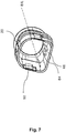
- Figur 7
- zeigt eine perspektivische Ansicht eines zweiten Gehäuseelements des Steckverbinders.
- Figur 8
- zeigt entgegen der Einsteckrichtung blickend eine Draufsicht auf den Steckverbinder.
-
Figuren 1 und2 zeigen einen Steckverbinder 10, welcher zumindest abschnittsweise einen in dem Steckverbinder 10 angeordneten Stecker 12 und zumindest abschnittsweise ein mit dem Stecker 12 verbundenes Kabel 14 umgibt. Der Steckverbinder 10 ist dazu ausgelegt, mit einer wie in denFiguren 4 und5 gezeigten Steckverbinderbuchse 16 verbunden zu werden. Dazu wird der Steckverbinder 10 in Richtung der Einsteckrichtung E bewegt, um den Steckverbinder 10 mit der Steckverbinderbuchse 16 zu verbinden. Ferner weist der Steckverbinder 10 ein erstes Gehäuseelement 18 auf, welches in dem Steckverbinder 10 innenliegend angeordnet ist. Das erste Gehäuseelement 18 umgibt zumindest abschnittsweise entlang der Einsteckrichtung E den Stecker 12 und das Kabel 14. Des Weiteren zeigen dieFiguren 1 und2 ein zweites Gehäuseelement 20 des Steckverbinders 10, welches außenliegend angeordnet ist und das erste Gehäuseelement 18 zumindest abschnittsweise entlang der Einsteckrichtung umgibt. Der Steckverbinder 10 ist dazu ausgebildet, dass das zweite Gehäuseelement 20 in Bezug auf das erste Gehäuseelement 18 entlang der Einsteckrichtung E bzw. entlang der Längsachse L des Steckverbinder 10 bewegbar ist. Die Längsachse L liegt dabei im Wesentlichen parallel zur Einsteckrichtung E. - Des Weiteren weist der Steckverbinder 10 mindestens ein steckverbinderseitiges Verriegelungselement 22 auf. In der in den Figuren dargestellten Ausführungsform des Steckverbinders 10, weist der Steckverbinder 10 genau zwei steckverbinderseitige Verriegelungselemente 22 auf, welche zumindest abschnittsweise zwischen dem ersten Gehäuseelement 18 und dem zweiten Gehäuseelement 20 angeordnet sind. Die steckverbinderseitigen Verriegelungselemente 22 sind insbesondere dazu ausgelegt, mit entsprechenden steckverbinderbuchsenseitigen Verriegelungselementen 24 (siehe
Figuren 4 und5 ), welche an der Steckverbinderbuchse 16 angeordnet sind (sieheFiguren 4 und5 ) verriegelt zu werden, wenn der Steckverbinder 10 mit der Steckverbinderbuchse 16 verbunden ist. - Der Aufbau des Steckverbinders 10 wird im Folgenden insbesondere mit Bezugnahme auf die
Figuren 2 und3 näher erläutert. Das erste Gehäuseelement 18 weist eine erste Zugangsöffnung 26 und eine zweite Zugangsöffnung 28 auf. Die erste Zugangsöffnung 26 und die zweite Zugangsöffnung 28 sind gegenüberliegend und voneinander beabstandet angeordnet und liegen im Wesentlichen senkrecht zur Längsachse L des Steckverbinders 10. Ferner sind die erste Zugangsöffnung 26 und die zweite Zugangsöffnung 28 durch eine Wand 30 des ersten Gehäuseelements 18 miteinander verbunden. Dabei bildet die erste Zugangsöffnung 26 ein, in Einsteckrichtung E liegendes, Ende des ersten Gehäuseelements 18 und die zweite Zugangsöffnung 28 bildet ein, in entgegen der Einsteckrichtung E liegendes, Ende des ersten Gehäuseelements 18. Die Wand 30 des ersten Gehäuseelements 18 ist somit dazu ausgelegt, den Stecker 12 und des Kabel 14 zumindest abschnittsweise entlang der Einsteckrichtung E zu umgeben. - Des Weiteren weist das zweite Gehäuseelement 20 eine erste Zugangsöffnung 32 und eine zweite Zugangsöffnung 34 auf, welche gegenüberliegend und voneinander beabstandet angeordnet sind. Ferner sind die erste Zugangsöffnung 32 und die zweite Zugangsöffnung 34 im Wesentlichen senkrecht zur Einsteckrichtung E bzw. zur Längsachse L des Steckverbinders 10 angeordnet. Ferner weist das zweite Gehäuseelement 20 eine Wand 36 auf, welche zwischen der ersten Zugangsöffnung 32 und der zweiten Zugangsöffnung 34 angeordnet ist und sich zumindest abschnittsweise entlang der Einsteckrichtung E bzw. Längsachse L des Steckverbinders 10 erstreckt. Die Wand 36 des zweiten Gehäuseelements 20 umgibt dabei zumindest abschnittsweise das erste Gehäuseelement 18.
- An einer, nach außen zeigenden, Fläche 38 der Wand 30 des ersten Gehäuseelements 18 ist mindestens ein Aufnahmeelement 40 vorgesehen, welches zur Befestigung des steckverbinderseitigen Verriegelungselements 22 vorgesehen ist. Insbesondere ist das Aufnahmeelement 40 dazu ausgebildet, einen Befestigungsabschnitt 42 des steckverbinderseitigen Verriegelungselements 22 aufzunehmen. Insbesondere zeigen die
Figuren 3 und4 genau zwei Aufnahmeelemente 40, welche an der Fläche 30 angeordnet sind, wobei an jedem Aufnahmeelement 40 genau ein steckverbinderseitiges Verriegelungselement 22 befestigbar ist. Die Aufnahmeelemente 40 sind dabei in Bezug auf die Längsachse L des Steckverbinders 10 gegenüberliegend angeordnet. Das Aufnahmeelement 40 ist insbesondere schlitzförmig ausgebildet, wobei zum Befestigen des steckverbinderseitigen Verriegelungselements 22 an dem Aufnahmeelement 40, der Befestigungsabschnitt 42 in Einsteckrichtung in das Aufnahmeelement 40 einführbar ist. Ferner sind das Aufnahmeelement 40 und der Befestigungsabschnitt 42 miteinander verriegelbar ausgebildet, so dass das steckverbinderseitige Verriegelungselement 22 sicher an dem ersten Gehäuseelement 18 befestigbar ist. Entgegen der Einsteckrichtung E schließt sich an den Befestigungsabschnitt 42 ein um ca. 180° gebogener Abschnitt 44 an, welcher den Befestigungsabschnitt 42 mit einem Verriegelungsabschnitt 46 des steckverbinderseitigen Verriegelungselements 22 verbindet. Ausgehend von dem gebogenen Abschnitt 44 erstreckt sich der Verriegelungsabschnitt 46 im Wesentlichen in Richtung der Einsteckrichtung E. Der Verriegelungsabschnitt 46 ist insbesondere dazu ausgebildet, mit dem steckverbinderbuchsenseitigen Verriegelungselement 24 verriegelt zu werden (sieheFigur 5 ). - Ferner kontaktiert der Verriegelungsabschnitt 46 das zweite Gehäuseelement 20 derart, dass durch eine Relativbewegung des zweiten Gehäuseelements 20 in Bezug auf das erste Gehäuseelement 18 entgegen der Einsteckrichtung E, der Verriegelungsabschnitt 46 nach außen, das heißt weg von der Längsachse L des Steckverbinders 10, bewegbar ist. Durch diese Relativbewegung des zweiten Gehäuseelements 20 entgegen der Einsteckrichtung E, wird eine Verriegelung des steckverbinderseitigen Verriegelungselements 22 bzw. des Verriegelungsabschnitts 46 mit dem steckverbinderbuchsenseitigen Verriegelungselement 24 aufgehoben. Mit anderen Worten, durch die zuvor beschriebene Relativbewegung kann das zweite Gehäuseelement 20 und damit verbunden der Verriegelungsabschnitt 46 in eine Entriegelungsposition bewegt werden. Ferner ist das steckverbinderseitige Verriegelungselement 22 rückstellfähig ausgebildet, sodass bei einer Relativbewegung des zweiten Gehäuseelements 20 gegenüber dem ersten Gehäuseelement 18 in Einsteckrichtung E, das steckverbinderseitige Verriegelungselement 22 bzw. der Verriegelungsabschnitt 46 selbstständig eine Verriegelungsposition einnimmt, bei der das steckverbinderseitige Verriegelungselement 22 bzw. der Verbindungsabschnitt 46 mit dem steckverbinderbuchsenseitigen Verriegelungselement 24 verriegelbar ist.
- Ferner weist der Verriegelungsabschnitt 46 eine Verriegelungsöffnung 47 auf, welche es ermöglicht, dass der Verriegelungsabschnitt 46 das steckverbinderbuchsenseitigen Verriegelungselement 24 im verriegelten Zustand hintergreift. Wie in
Figur 4 gezeigt, ist das steckverbinderbuchsenseitige Verriegelungselement 24 beispielsweise als Vorsprung bzw. Nase ausgebildet. - Wie insbesondere in
Figur 3 gezeigt, weist der Verriegelungsabschnitt 46 an einem in Einsteckrichtung E liegenden Ende eine gegenüber der Einsteckrichtung E bzw. Längsachse L angestellte Kontaktierungsfläche 48 auf, welche zumindest abschnittsweise an einem durch eine in dem zweiten Gehäuseelement 20 vorgesehene Durchtrittsöffnung 50 gebildeten Auflageabschnitt 50 anliegt. Die Kontaktierungsfläche 48 ist derart gegenüber der Längsachse L angestellt, dass der Abstand der Kontaktierungsfläche 48 zur Längsachse L sich in Einsteckrichtung E vergrößert. Eine Relativbewegung des zweiten Gehäuseelements 20 in Bezug auf das erste Gehäuseelement 18 entgegen der Einsteckrichtung E führt somit zu einer nach außen gerichteten Verschiebung des Verriegelungsabschnitts 46, wodurch das Hintergreifen des steckverbinderbuchsenseitigen Verriegelungselements 24 aufhebbar ist. Ferner ermöglicht die Rückstellfähigkeit des steckverbinderseitigen Verriegelungselements 22, die Ausübung einer in Einsteckrichtung E wirkenden Kraft auf das zweite Gehäuseelement 20, sodass das zweite Gehäuseelement 20 durch das steckverbinderseitige Verriegelungselement 22 in Richtung der Einsteckrichtung E bewegbar bzw. verlagerbar ist. - Wie aus der
Figur 3 ersichtlich, sind die zwei Aufnahmeelemente 40 in Bezug auf die Längsachse L gegenüberliegend angeordnet. Ebenso sind die zwei steckverbinderseitigen Verriegelungselemente 22 in Bezug auf die Längsachse L des Steckverbinders 10 gegenüberliegend angeordnet. - Wie in
Figur 3 gezeigt, weist der Verriegelungsabschnitt 46 mindestens ein nach innen gerichtetes Kontaktierungselement 54 auf, welches dazu ausgebildet ist im verbundenen Zustand von Steckverbinder 10 und Steckverbinderbuchse 16, die Steckverbinderbuchse 16 zu kontaktieren. Des Weiteren weist das steckverbinderseitige Verriegelungselement 22 zumindest ein nach außen gerichtetes Kontaktierungselement 56 auf, welches dazu ausgebildet ist, die Innenseite des zweiten Gehäuseelements 20 zu kontaktieren. Ferner ist das erste Gehäuseelement 18 dazu ausgebildet, eine Abschirmung des Steckers 12 bzw. des Kabels 14 elektrisch zu kontaktieren. Ferner ist die Steckverbinderbuchse 16 dazu ausgebildet, eine Abschirmung der in der Steckverbinderbuchse 16 angeordneten Steckerbuchse bzw. eines mit der Steckerbuchse verbundenen Kabels (nicht gezeigt) elektrisch zu kontaktieren. Ferner ist das steckverbinderseitige Verriegelungselement 22 dazu ausgebildet, das erste Gehäuseelement 18 elektrisch mit dem zweiten Gehäuseelement 20 zu verbinden, sodass im verbundenen Zustand von Steckverbinder 10 und Steckverbinderbuchse 16, die steckverbinderseitige Abschirmung und die steckverbinderbuchsenseitige Abschirmung elektrisch miteinander verbunden sind. - Wie in den
Figuren 6 bis 8 gezeigt, ist zwischen dem ersten Gehäuseelement 18 und dem zweiten Gehäuseelement 20 mindestens ein Führungselement 60 angeordnet. Das Führungselement 60 ist dazu ausgelegt, eine Linearbewegung des zweiten Gehäuseelements 20 in Bezug auf das erste Gehäuseelement 18 entlang der Einsteckrichtung E zu unterstützen. Wie inFigur 6 gezeigt, besteht das Führungselement 60 aus einer an der Außenseite des ersten Gehäuseelements 18 angeordneten Führungsnase 62, welche an der nach außen zeigenden Fläche 38 der Wand 30 des ersten Gehäuseelements 18 angeordnet ist. Wie in denFiguren 7 und8 gezeigt, weist das zweite Gehäuseelement 20 an einer Innenseite bzw. an der nach innen zeigenden Fläche der Wand 36 des zweiten Gehäuseelements 20 eine Führungsnut 64 auf, in der die Führungsnase 62 führbar ist. Durch das Führungselement 60 kann ein Verdrehen des zweiten Gehäuseelements 20 gegenüber dem ersten Gehäuseelement 18 in Bezug auf die Längsachse L verhindert werden. Die in denFiguren 6-8 gezeigte Ausführungsform weist insbesondere genau zwei Führungselemente 60 auf, welche in Bezug auf die Längsachse L gegenüberliegend angeordnet sind. Des Weiteren weist die Führungsnut 64 einen Anschlag aus, welcher eine Relativbewegung des zweiten Gehäuseelements 20 gegenüber dem ersten Gehäuseelement 18 in Richtung der Einsteckrichtung E begrenzt. - Wie in
Figur 8 dargestellt, sind die Führungselemente 60 und die steckverbinderseitigen Verriegelungselemente 22 in Einsteckrichtung E blickend in Bezug auf die Längsachse L um 90° versetzt angeordnet. -
Figur 4 zeigt beispielhaft eine Steckverbinderbuchse 16, welche aus einem plattenförmigen Grundelement 70 besteht, welches im Wesentlichen senkrecht zur Einsteckrichtung E angeordnet ist. Ferner weist das Grundelement 70 eine Öffnung 72 auf, in welcher zumindest abschnittsweise eine steckverbinderseitige Steckerbuchse angeordnet werden kann. Beim Verbinden des Steckverbinders 10 mit der Steckverbinderbuchse 16 wird der Stecker 12 mit der Steckverbinderbuchse verbunden. Des Weiteren weist die Steckverbinderbuchse 16 eine Wandung auf, welche als Verbindungsabschnitt 72 ausgebildet ist. Der Verbindungsabschnitt 72 umgibt zumindest abschnittsweise die Längsachse L der Steckverbinderbuchse 16. Ferner ist der Verbindungsabschnitt 72 dazu ausgebildet, im verbundenen Zustand von Steckverbinder 10 und Steckverbinderbuchse 16, in einen zwischen dem ersten Gehäuseelement 18 und dem zweiten Gehäuseelement 20 befindlichen Hohlraum 74 hineinzuragen. Ferner weist der Verbindungsabschnitt 72 außenliegend die steckverbinderbuchsenseitigen Verriegelungselemente 24 auf, welche in Bezug auf die Längsachse L gegenüberliegend angeordnet sind. - Wie in der
Figur 8 dargestellt, weist das zweite Gehäuseelement 20 in Einsteckrichtung E blickend eine Form auf, welche ein Verdrehen des Steckverbinders 10 gegenüber der Steckverbinderbuchse 16 verhindert. Insbesondere weist das zweite Gehäuseelement 20 einen ersten Gehäuseabschnitt 76 und einen zweiten Gehäuseabschnitt 78 auf, welche in Bezug auf die Längsachse L gegenüberliegend angeordnet sind und sich im Wesentlichen parallel zur Einsteckrichtung E erstrecken. Des Weiteren weist das zweite Gehäuseelement 20 einen dritten Gehäuseabschnitt 80 auf, welcher senkrecht zu dem ersten Gehäuseabschnitt 76 und zu dem zweiten Gehäuseabschnitt 78 angeordnet ist. Ferner erstreckt sich der dritte Gehäuseabschnitt 80 ebenfalls parallel zur Einsteckrichtung E. Des Weiteren weist das zweite Gehäuseelement 20 einen vierten Gehäuseabschnitt 82 auf, welcher in Bezug auf die Längsachse L dem dritten Gehäuseabschnitt 80 gegenüberliegend angeordnet ist. Der vierte Gehäuseabschnitt 82 weist dabei in Einsteckrichtung E blickend eine gewölbte bzw. gekrümmte Form auf. Ferner ist entsprechend der Form des zweiten Gehäuseelements 20 der Verbindungabschnitt 72 geformt, sodass das zweite Gehäuseelement 20 verdrehsicher mit der Steckverbinderbuchse 16 verbunden werden kann. - Ferner zeigt
Figur 5 einen verbundenen Zustand des Steckverbinders 10 mit der Steckverbinderbuchse 16. Im verbundenen Zustand ragt der Verbindungsabschnitt 72 zumindest abschnittsweise in den Hohlraum zwischen dem ersten Gehäuseelement 18 und dem zweiten Gehäuseelement 20 hinein. Ferner zeigtFigur 5 wie der Verriegelungsabschnitt 46 des steckverbinderbuchsenseitige Verriegelungselement 24 hintergreift. - Wie in den
Figuren 2 und5 gezeigt, kann der Steckverbinder 10 eine zumindest bereichsweise flexible Kabelführung 58 aufweisen, welche das Kabel 14 zumindest abschnittsweise umgibt, wobei die Kabelführung 58 an den Durchmesser des Kabels 14 anpassbar ist. Vorteilhafterweise kann die Kabelführung 58 das im Steckverbinder 10 angeordnete Kabel 14 vor Knicken und mechanischen Beanspruchungen schützen. Die Kabelführung 58 umgibt das Kabel 14 dabei zumindest abschnittsweise entlang der Einsteckrichtung E. Ferner kann die Kabelführung 58 mit dem ersten Gehäuseelement 18 verbindbar sein. Insbesondere kann die Kabelführung 58 an einem entgegen der Einsteckrichtung E liegenden Ende des ersten Gehäuseelements 18 angeordnet sein. -
- 10
- Steckverbinder
- 12
- Stecker
- 14
- Kabel
- 16
- Steckverbinderbuchse
- 18
- erstes Gehäuseelement
- 20
- zweites Gehäuseelement
- 22
- steckverbinderseitiges Verriegelungselement
- 24
- steckverbinderbuchsenseitiges Verriegelungselement
- 26
- erste Zugangsöffnung erstes Gehäuseelement
- 28
- zweite Zugangsöffnung erstes Gehäuseelement
- 30
- Wand des erstes Gehäuseelements
- 32
- erste Zugangsöffnung zweites Gehäuseelement
- 34
- zweite Zugangsöffnung zweites Gehäuseelement
- 36
- Wand zweites Gehäuseelements
- 38
- nach außen zeigende Fläche der Wand 30
- 40
- Aufnahmeelement
- 42
- Befestigungsabschnitt
- 44
- gebogener Abschnitt
- 46
- Verriegelungsabschnitt
- 47
- Verriegelungsöffnung
- 48
- Kontaktierungsfläche
- 50
- Durchtrittsöffnung
- 52
- Auflageabschnitt
- 54
- Kontaktierungselement (nach innen gerichtet)
- 56
- Kontaktierungselement (nach außen gerichtet)
- 58
- Kabelführung
- 60
- Führungselement
- 62
- Führungsnase
- 64
- Führungsnut
- 66
- Anschlag
- 70
- Grundelement
- 72
- Verbindungsabschnitt
- 74
- Hohlraum
- 76
- erster Gehäuseabschnitt
- 78
- zweiter Gehäuseabschnitt
- 80
- dritter Gehäuseabschnitt
- 82
- vierter Gehäuseabschnitt
- E
- Einsteckrichtung
- L
- Längsachse
Claims (15)
- Steckverbinder (10), insbesondere einen Push-Pull-Verbinder, zum Verbinden mit einer Steckverbinderbuchse (16), aufweisend:- ein erstes Gehäuseelement (18), welches dazu ausgebildet ist, einen mit einem Kabel (14) verbundenen Stecker (12) zumindest teilweise entlang einer Einsteckrichtung (E) des Steckverbinders (10) in die Steckverbinderbuchse (16) zu umgeben;- mindestens ein an dem ersten Gehäuseelement (18) angeordnetes steckverbinderseitiges Verriegelungselement (22) zum Verriegeln des Steckverbinders (10) mit der Steckverbinderbuchse (16), wobei das mindestens eine steckverbinderseitige Verriegelungselement (22) dazu ausgebildet ist, in einem verriegelten Zustand des Steckverbinders (10) mit der Steckverbinderbuchse (16), mit einem steckverbinderbuchsenseitigen Verriegelungselement (24) zu verriegeln; und- ein zweites Gehäuseelement (20), welches zumindest teilweise das erste Gehäuseelement (18) und das steckverbinderseitige Verriegelungselement (22) umgibt, wobei das zweite Gehäuseelement (20) in Bezug auf das erste Gehäuseelement (18) entlang der Einsteckrichtung (E) bewegbar ist; undwobei durch ein Bewegen des zweiten Gehäuseelements (20) entgegen der Einsteckrichtung (E) in eine Entriegelungsposition, der Steckverbinder (10) von der Steckverbinderbuchse (16) lösbar ist.
- Steckverbinder (10) nach Anspruch 1, wobei das mindestens eine steckverbinderseitige Verriegelungselement (22) zumindest abschnittsweise in einem, zwischen dem ersten Gehäuseelement (18) und dem zweiten Gehäuseelement (20) befindlichen, Hohlraum (74) angeordnet ist.
- Steckverbinder (10) nach Anspruch 1 oder 2, wobei das mindestens eine steckverbinderseitige Verriegelungselement (22) dazu ausgebildet ist, in dem verriegelten Zustand, das steckverbinderbuchsenseitigen Verriegelungselement (24) zu hintergreifen.
- Steckverbinder (10) nach einem der vorangegangenen Ansprüche, wobei das mindestens eine steckverbinderseitige Verriegelungselement (22) durch das Bewegen des zweiten Gehäuseelements (20) in die Entriegelungsposition zumindest abschnittsweise nach außen bewegbar ist, um eine Verriegelung mit dem steckverbinderbuchsenseitigen Verriegelungselement (24) zu lösen.
- Steckverbinder (10) nach einem der vorangegangenen Ansprüche, wobei das mindestens eine steckverbinderseitige Verriegelungselement (22) rückstellfähig ausgebildet ist und in der Entriegelungsposition eine, im Wesentlichen in Richtung Kabel (14) gerichtete, Rückstellkraft ausübt, und wobei das mindestens eine steckverbinderseitige Verriegelungselement (22) das zweite Gehäuseelement (20) derart kontaktiert, dass in der Entriegelungsposition auf das zweite Gehäuseelement (20) eine in Richtung der Einsteckrichtung (E) wirkende Kraft ausgeübt wird.
- Steckverbinder (10) nach einem der vorangegangenen Ansprüche, wobei das mindestens eine steckverbinderseitige Verriegelungselement (22) einen Befestigungsabschnitt (42) und einen mit dem Befestigungsabschnitt verbundenen Verriegelungsabschnitt (46) aufweist,
wobei das mindestens eine steckverbinderseitige Verriegelungselement (22) mittels des Befestigungsabschnitts (42) an dem ersten Gehäuseelement (18) befestigbar ist, und
wobei der Verriegelungsabschnitt (46) sich in Richtung der Einsteckrichtung (E) erstreckt und zumindest abschnittsweise zwischen dem Befestigungsabschnitt (42) und dem zweiten Gehäuseelement (20) angeordnet ist. - Steckverbinder (10) nach Anspruch 6, wobei der Verriegelungsabschnitt (46) an einem in Einsteckrichtung (E) liegenden Ende eine gegenüber der Einsteckrichtung (E) angestellte Kontaktierungsfläche (48) aufweist, welche zumindest abschnittsweise an einem durch eine in dem zweiten Gehäuseelement (20) vorgesehene Durchtrittsöffnung (50) gebildeten Auflageabschnitt (52) anliegt.
- Steckverbinder (10) nach Anspruch 7, wobei durch Bewegen des zweiten Gehäuseelements (20) in die Entriegelungsposition, der Auflageabschnitt (52) entgegen der Einsteckrichtung (E) an der Kontaktierungsfläche (48) entlangführbar ist.
- Steckverbinder (10) nach einem der vorangegangenen Ansprüche, wobei das mindestens eine steckverbinderseitige Verriegelungselement (22) eine Öffnung (47) aufweist, die dazu ausgebildet ist, das steckverbinderbuchsenseitigen Verriegelungselement (24) zu hintergreifen, und wobei das steckverbinderbuchsenseitige Verriegelungselement (24) bevorzugt als Nase ausgebildet ist.
- Steckverbinder (10) nach einem der vorangegangenen Ansprüche, wobei das mindestens eine steckverbinderseitige Verriegelungselement (22) und das erste Gehäuseelement (18) dazu ausgebildet sind, eine elektrisch leitende Verbindung zwischen dem zweiten Gehäuseelement (20) und einer Abschirmung eines Kabels (14), welches zumindest abschnittsweise von dem ersten Gehäuseelement (18) umgeben ist, bereitzustellen, und/oder eine elektrisch leitende Verbindung zwischen der Steckverbinderbuchse (16) und der Abschirmung bereitzustellen
- Steckverbinder (10) nach einem der vorangegangenen Ansprüche, ferner aufweisend eine zumindest bereichsweise flexible Kabelführung (58), welche das Kabel (14) zumindest abschnittsweise umgibt, und wobei die Kabelführung (58) an den Durchmesser des Kabels (14) anpassbar ist.
- Steckerverbinder (10) nach einem der vorangegangenen Ansprüche, wobei der Steckverbinder (10) dazu ausgebildet ist, verdrehsicher mit der Steckverbinderbuchse (16) verbunden zu werden.
- Steckverbinder (10) nach einem der vorangegangenen Ansprüche, wobei der Steckverbinder (10) und die Steckverbinderbuchse (16) durch eine Linearbewegung des zweiten Gehäuseelements (20) entlang der Einsteckrichtung (E) entriegelbar und verriegelbar sind.
- Steckverbindersystem aufweisend:- einen Steckverbinder (10) nach einem der vorangegangenen Ansprüche 1-13 zum Aufnehmen eines mit einem Kabel (14) verbundenen Steckers (12); und- eine mit dem Steckverbinder (10) verriegelbare Steckverbinderbuchse (16).
- Verwendung eines Steckverbinders (10) nach einem der Ansprüche 1-13 zum Verbinden des Steckverbinders (10) mit einer Steckverbinderbuchse (16).
Applications Claiming Priority (1)
| Application Number | Priority Date | Filing Date | Title |
|---|---|---|---|
| DE102020000359.1A DE102020000359B4 (de) | 2020-01-21 | 2020-01-21 | Steckverbinder, insbesondere Push-Pull-Verbinder, zum Verbinden mit einer Steckverbinderbuchse, Steckverbindersystem und Verwendung eines Steckverbinders |
Publications (3)
| Publication Number | Publication Date |
|---|---|
| EP3855579A1 true EP3855579A1 (de) | 2021-07-28 |
| EP3855579C0 EP3855579C0 (de) | 2023-10-11 |
| EP3855579B1 EP3855579B1 (de) | 2023-10-11 |
Family
ID=74194649
Family Applications (1)
| Application Number | Title | Priority Date | Filing Date |
|---|---|---|---|
| EP21152679.3A Active EP3855579B1 (de) | 2020-01-21 | 2021-01-21 | Steckverbinder, insbesondere push-pull-verbinder, zum verbinden mit einer steckverbinderbuchse, steckverbindersystem und verwendung eines steckverbinders |
Country Status (2)
| Country | Link |
|---|---|
| EP (1) | EP3855579B1 (de) |
| DE (1) | DE102020000359B4 (de) |
Citations (3)
| Publication number | Priority date | Publication date | Assignee | Title |
|---|---|---|---|---|
| FR2749984A1 (fr) * | 1996-06-18 | 1997-12-19 | Cinch Connecteurs Sa | Connecteur electrique |
| US7175464B2 (en) * | 2005-06-04 | 2007-02-13 | Harting Electric Gmbh & Co. Kg | Latching device for a connector |
| US20090304334A1 (en) * | 2008-06-09 | 2009-12-10 | David Robert | Female Connector for Self-Locking Connector System |
Family Cites Families (5)
| Publication number | Priority date | Publication date | Assignee | Title |
|---|---|---|---|---|
| DE10236275B3 (de) | 2002-08-08 | 2004-01-08 | Harting Electronics Gmbh & Co. Kg | Verriegelungseinrichtung |
| DE202006005177U1 (de) | 2006-03-31 | 2006-06-08 | Harting Electronics Gmbh & Co. Kg | Metallischer Steckverbinder |
| DE202008005099U1 (de) | 2008-01-21 | 2009-06-18 | Weidmüller Interface GmbH & Co. KG | Steckverbindung mit Adaptergehäusen zur Aufnahme einer Stecker- bzw. einer Buchsenanordnung |
| LU93269B1 (de) | 2016-10-20 | 2018-05-30 | Phoenix Contact Gmbh & Co Kg Intellectual Property Licenses & Standards | Push-Pull-Steckverbinderteil mit einem Rastblech |
| DE202017006920U1 (de) | 2017-10-23 | 2018-11-09 | Phoenix Contact Gmbh & Co. Kg | Steckverbinderteil mit einer Spiralfeder zum axialen Vorspannen eines Gegensteckverbinderteils |
-
2020
- 2020-01-21 DE DE102020000359.1A patent/DE102020000359B4/de active Active
-
2021
- 2021-01-21 EP EP21152679.3A patent/EP3855579B1/de active Active
Patent Citations (3)
| Publication number | Priority date | Publication date | Assignee | Title |
|---|---|---|---|---|
| FR2749984A1 (fr) * | 1996-06-18 | 1997-12-19 | Cinch Connecteurs Sa | Connecteur electrique |
| US7175464B2 (en) * | 2005-06-04 | 2007-02-13 | Harting Electric Gmbh & Co. Kg | Latching device for a connector |
| US20090304334A1 (en) * | 2008-06-09 | 2009-12-10 | David Robert | Female Connector for Self-Locking Connector System |
Also Published As
| Publication number | Publication date |
|---|---|
| DE102020000359B4 (de) | 2024-03-28 |
| EP3855579C0 (de) | 2023-10-11 |
| EP3855579B1 (de) | 2023-10-11 |
| DE102020000359A1 (de) | 2021-07-22 |
Similar Documents
| Publication | Publication Date | Title |
|---|---|---|
| EP2846408B1 (de) | Elektrische Anschlussklemme | |
| DE10126957B4 (de) | Steckverbindung mit Mitteln zur Verhinderung eines unvollständig verbundenen Zustands | |
| DE102021129676B4 (de) | Steckverbindung mit Verriegelungs- und Entriegelungsvorrichtung | |
| DE4413936C2 (de) | Gehäuse für elektrische Verbinder mit Sekundärverriegelung | |
| DE112010005834T5 (de) | Steckerverbinder | |
| EP0353330A1 (de) | Buchsenkontakt | |
| DE2850440A1 (de) | Verriegelungsmechanismus zum koppeln und entkoppeln elektrischer verbinder | |
| DE102013106117B4 (de) | Steckverbinderanordnung und Steckverbindungssystem | |
| DE102020127203B4 (de) | Steckverbinderanordnung | |
| DE29516504U1 (de) | Elektrischer Steckverbinder mit hoher Dichte | |
| DE102021128761A1 (de) | Bidirektionales Kopfstück zum Zusammenstecken von Verbindern in mehreren Richtungen | |
| DE102019112576B3 (de) | Verbindergehäuse, Gegenverbindergehäuse und System | |
| DE69425829T2 (de) | Selbstverriegelnde Kontaktstruktur | |
| DE19714459A1 (de) | Steckverbinder mit einer Gehäuseverriegelung | |
| EP3987616B1 (de) | Steckmodul für ein reiheneinbaugerät und reiheneinbaugerät | |
| EP4170832B1 (de) | Steckverbinderanordnung zum verbinden von signalleitern | |
| DE69310439T2 (de) | Verriegelbarer elektrischer Verbinderanordnung | |
| EP3312944B1 (de) | Push-pull-steckverbinderteil mit einem rastblech | |
| EP2942839B1 (de) | Steckverbinder mit niederiger steck- und hoher kontaktnormalkraft | |
| WO2019161848A1 (de) | Steckverbinder mit polarisationselement sowie ein system und ein verfahren zum montieren, zum stecken und zum trennen dieses steckverbinders | |
| EP1154521B1 (de) | Steckverbinder und Verfahren zur Montage eines Steckverbinders | |
| DE102021122636A1 (de) | Steckverbindung | |
| EP3621157B1 (de) | Elektrische steckbuchse | |
| DE102020000359B4 (de) | Steckverbinder, insbesondere Push-Pull-Verbinder, zum Verbinden mit einer Steckverbinderbuchse, Steckverbindersystem und Verwendung eines Steckverbinders | |
| EP2731204A1 (de) | Verbinder mit Zugentlastungsvorrichtung |
Legal Events
| Date | Code | Title | Description |
|---|---|---|---|
| PUAI | Public reference made under article 153(3) epc to a published international application that has entered the european phase |
Free format text: ORIGINAL CODE: 0009012 |
|
| STAA | Information on the status of an ep patent application or granted ep patent |
Free format text: STATUS: THE APPLICATION HAS BEEN PUBLISHED |
|
| AK | Designated contracting states |
Kind code of ref document: A1 Designated state(s): AL AT BE BG CH CY CZ DE DK EE ES FI FR GB GR HR HU IE IS IT LI LT LU LV MC MK MT NL NO PL PT RO RS SE SI SK SM TR |
|
| STAA | Information on the status of an ep patent application or granted ep patent |
Free format text: STATUS: REQUEST FOR EXAMINATION WAS MADE |
|
| 17P | Request for examination filed |
Effective date: 20220120 |
|
| RBV | Designated contracting states (corrected) |
Designated state(s): AL AT BE BG CH CY CZ DE DK EE ES FI FR GB GR HR HU IE IS IT LI LT LU LV MC MK MT NL NO PL PT RO RS SE SI SK SM TR |
|
| GRAP | Despatch of communication of intention to grant a patent |
Free format text: ORIGINAL CODE: EPIDOSNIGR1 |
|
| STAA | Information on the status of an ep patent application or granted ep patent |
Free format text: STATUS: GRANT OF PATENT IS INTENDED |
|
| RIC1 | Information provided on ipc code assigned before grant |
Ipc: H01R 24/64 20110101ALN20230413BHEP Ipc: H01R 13/6583 20110101ALI20230413BHEP Ipc: H01R 13/633 20060101ALI20230413BHEP Ipc: H01R 13/627 20060101AFI20230413BHEP |
|
| RIC1 | Information provided on ipc code assigned before grant |
Ipc: H01R 24/64 20110101ALN20230503BHEP Ipc: H01R 13/6583 20110101ALI20230503BHEP Ipc: H01R 13/633 20060101ALI20230503BHEP Ipc: H01R 13/627 20060101AFI20230503BHEP |
|
| INTG | Intention to grant announced |
Effective date: 20230516 |
|
| GRAS | Grant fee paid |
Free format text: ORIGINAL CODE: EPIDOSNIGR3 |
|
| GRAA | (expected) grant |
Free format text: ORIGINAL CODE: 0009210 |
|
| STAA | Information on the status of an ep patent application or granted ep patent |
Free format text: STATUS: THE PATENT HAS BEEN GRANTED |
|
| AK | Designated contracting states |
Kind code of ref document: B1 Designated state(s): AL AT BE BG CH CY CZ DE DK EE ES FI FR GB GR HR HU IE IS IT LI LT LU LV MC MK MT NL NO PL PT RO RS SE SI SK SM TR |
|
| REG | Reference to a national code |
Ref country code: GB Ref legal event code: FG4D Free format text: NOT ENGLISH |
|
| REG | Reference to a national code |
Ref country code: CH Ref legal event code: EP |
|
| REG | Reference to a national code |
Ref country code: DE Ref legal event code: R096 Ref document number: 502021001645 Country of ref document: DE |
|
| REG | Reference to a national code |
Ref country code: IE Ref legal event code: FG4D Free format text: LANGUAGE OF EP DOCUMENT: GERMAN |
|
| U01 | Request for unitary effect filed |
Effective date: 20231110 |
|
| U07 | Unitary effect registered |
Designated state(s): AT BE BG DE DK EE FI FR IT LT LU LV MT NL PT SE SI Effective date: 20231117 |
|
| U20 | Renewal fee for the european patent with unitary effect paid |
Year of fee payment: 4 Effective date: 20240111 |
|
| PG25 | Lapsed in a contracting state [announced via postgrant information from national office to epo] |
Ref country code: GR Free format text: LAPSE BECAUSE OF FAILURE TO SUBMIT A TRANSLATION OF THE DESCRIPTION OR TO PAY THE FEE WITHIN THE PRESCRIBED TIME-LIMIT Effective date: 20240112 |
|
| PG25 | Lapsed in a contracting state [announced via postgrant information from national office to epo] |
Ref country code: IS Free format text: LAPSE BECAUSE OF FAILURE TO SUBMIT A TRANSLATION OF THE DESCRIPTION OR TO PAY THE FEE WITHIN THE PRESCRIBED TIME-LIMIT Effective date: 20240211 |
|
| PG25 | Lapsed in a contracting state [announced via postgrant information from national office to epo] |
Ref country code: ES Free format text: LAPSE BECAUSE OF FAILURE TO SUBMIT A TRANSLATION OF THE DESCRIPTION OR TO PAY THE FEE WITHIN THE PRESCRIBED TIME-LIMIT Effective date: 20231011 |
|
| PG25 | Lapsed in a contracting state [announced via postgrant information from national office to epo] |
Ref country code: IS Free format text: LAPSE BECAUSE OF FAILURE TO SUBMIT A TRANSLATION OF THE DESCRIPTION OR TO PAY THE FEE WITHIN THE PRESCRIBED TIME-LIMIT Effective date: 20240211 Ref country code: GR Free format text: LAPSE BECAUSE OF FAILURE TO SUBMIT A TRANSLATION OF THE DESCRIPTION OR TO PAY THE FEE WITHIN THE PRESCRIBED TIME-LIMIT Effective date: 20240112 Ref country code: ES Free format text: LAPSE BECAUSE OF FAILURE TO SUBMIT A TRANSLATION OF THE DESCRIPTION OR TO PAY THE FEE WITHIN THE PRESCRIBED TIME-LIMIT Effective date: 20231011 |
|
| PG25 | Lapsed in a contracting state [announced via postgrant information from national office to epo] |
Ref country code: RS Free format text: LAPSE BECAUSE OF FAILURE TO SUBMIT A TRANSLATION OF THE DESCRIPTION OR TO PAY THE FEE WITHIN THE PRESCRIBED TIME-LIMIT Effective date: 20231011 Ref country code: PL Free format text: LAPSE BECAUSE OF FAILURE TO SUBMIT A TRANSLATION OF THE DESCRIPTION OR TO PAY THE FEE WITHIN THE PRESCRIBED TIME-LIMIT Effective date: 20231011 Ref country code: NO Free format text: LAPSE BECAUSE OF FAILURE TO SUBMIT A TRANSLATION OF THE DESCRIPTION OR TO PAY THE FEE WITHIN THE PRESCRIBED TIME-LIMIT Effective date: 20240111 Ref country code: HR Free format text: LAPSE BECAUSE OF FAILURE TO SUBMIT A TRANSLATION OF THE DESCRIPTION OR TO PAY THE FEE WITHIN THE PRESCRIBED TIME-LIMIT Effective date: 20231011 |
|
| REG | Reference to a national code |
Ref country code: DE Ref legal event code: R097 Ref document number: 502021001645 Country of ref document: DE |
|
| PG25 | Lapsed in a contracting state [announced via postgrant information from national office to epo] |
Ref country code: CZ Free format text: LAPSE BECAUSE OF FAILURE TO SUBMIT A TRANSLATION OF THE DESCRIPTION OR TO PAY THE FEE WITHIN THE PRESCRIBED TIME-LIMIT Effective date: 20231011 |
|
| PG25 | Lapsed in a contracting state [announced via postgrant information from national office to epo] |
Ref country code: SK Free format text: LAPSE BECAUSE OF FAILURE TO SUBMIT A TRANSLATION OF THE DESCRIPTION OR TO PAY THE FEE WITHIN THE PRESCRIBED TIME-LIMIT Effective date: 20231011 |
|
| PG25 | Lapsed in a contracting state [announced via postgrant information from national office to epo] |
Ref country code: SM Free format text: LAPSE BECAUSE OF FAILURE TO SUBMIT A TRANSLATION OF THE DESCRIPTION OR TO PAY THE FEE WITHIN THE PRESCRIBED TIME-LIMIT Effective date: 20231011 Ref country code: SK Free format text: LAPSE BECAUSE OF FAILURE TO SUBMIT A TRANSLATION OF THE DESCRIPTION OR TO PAY THE FEE WITHIN THE PRESCRIBED TIME-LIMIT Effective date: 20231011 Ref country code: RO Free format text: LAPSE BECAUSE OF FAILURE TO SUBMIT A TRANSLATION OF THE DESCRIPTION OR TO PAY THE FEE WITHIN THE PRESCRIBED TIME-LIMIT Effective date: 20231011 Ref country code: CZ Free format text: LAPSE BECAUSE OF FAILURE TO SUBMIT A TRANSLATION OF THE DESCRIPTION OR TO PAY THE FEE WITHIN THE PRESCRIBED TIME-LIMIT Effective date: 20231011 |
|
| PLBE | No opposition filed within time limit |
Free format text: ORIGINAL CODE: 0009261 |
|
| STAA | Information on the status of an ep patent application or granted ep patent |
Free format text: STATUS: NO OPPOSITION FILED WITHIN TIME LIMIT |
|
| PG25 | Lapsed in a contracting state [announced via postgrant information from national office to epo] |
Ref country code: MC Free format text: LAPSE BECAUSE OF FAILURE TO SUBMIT A TRANSLATION OF THE DESCRIPTION OR TO PAY THE FEE WITHIN THE PRESCRIBED TIME-LIMIT Effective date: 20231011 |
|
| PG25 | Lapsed in a contracting state [announced via postgrant information from national office to epo] |
Ref country code: MC Free format text: LAPSE BECAUSE OF FAILURE TO SUBMIT A TRANSLATION OF THE DESCRIPTION OR TO PAY THE FEE WITHIN THE PRESCRIBED TIME-LIMIT Effective date: 20231011 |
|
| REG | Reference to a national code |
Ref country code: CH Ref legal event code: PL |
|
| 26N | No opposition filed |
Effective date: 20240712 |
|
| PG25 | Lapsed in a contracting state [announced via postgrant information from national office to epo] |
Ref country code: CH Free format text: LAPSE BECAUSE OF NON-PAYMENT OF DUE FEES Effective date: 20240131 |
|
| PG25 | Lapsed in a contracting state [announced via postgrant information from national office to epo] |
Ref country code: CH Free format text: LAPSE BECAUSE OF NON-PAYMENT OF DUE FEES Effective date: 20240131 |
|
| PG25 | Lapsed in a contracting state [announced via postgrant information from national office to epo] |
Ref country code: IE Free format text: LAPSE BECAUSE OF NON-PAYMENT OF DUE FEES Effective date: 20240121 |
|
| PG25 | Lapsed in a contracting state [announced via postgrant information from national office to epo] |
Ref country code: IE Free format text: LAPSE BECAUSE OF NON-PAYMENT OF DUE FEES Effective date: 20240121 |
|
| U20 | Renewal fee for the european patent with unitary effect paid |
Year of fee payment: 5 Effective date: 20250129 |
|
| PG25 | Lapsed in a contracting state [announced via postgrant information from national office to epo] |
Ref country code: CY Free format text: LAPSE BECAUSE OF FAILURE TO SUBMIT A TRANSLATION OF THE DESCRIPTION OR TO PAY THE FEE WITHIN THE PRESCRIBED TIME-LIMIT; INVALID AB INITIO Effective date: 20210121 |
|
| PG25 | Lapsed in a contracting state [announced via postgrant information from national office to epo] |
Ref country code: HU Free format text: LAPSE BECAUSE OF FAILURE TO SUBMIT A TRANSLATION OF THE DESCRIPTION OR TO PAY THE FEE WITHIN THE PRESCRIBED TIME-LIMIT; INVALID AB INITIO Effective date: 20210121 |
|
| PG25 | Lapsed in a contracting state [announced via postgrant information from national office to epo] |
Ref country code: TR Free format text: LAPSE BECAUSE OF FAILURE TO SUBMIT A TRANSLATION OF THE DESCRIPTION OR TO PAY THE FEE WITHIN THE PRESCRIBED TIME-LIMIT Effective date: 20231011 |
|
| U20 | Renewal fee for the european patent with unitary effect paid |
Year of fee payment: 6 Effective date: 20260128 |
|
| PGFP | Annual fee paid to national office [announced via postgrant information from national office to epo] |
Ref country code: GB Payment date: 20260128 Year of fee payment: 6 |