EP3854974B1 - Duschkabinenschiebetürsystem - Google Patents
Duschkabinenschiebetürsystem Download PDFInfo
- Publication number
- EP3854974B1 EP3854974B1 EP20152871.8A EP20152871A EP3854974B1 EP 3854974 B1 EP3854974 B1 EP 3854974B1 EP 20152871 A EP20152871 A EP 20152871A EP 3854974 B1 EP3854974 B1 EP 3854974B1
- Authority
- EP
- European Patent Office
- Prior art keywords
- sliding door
- shower cubicle
- driver
- cubicle sliding
- release position
- Prior art date
- Legal status (The legal status is an assumption and is not a legal conclusion. Google has not performed a legal analysis and makes no representation as to the accuracy of the status listed.)
- Active
Links
Images


Classifications
-
- E—FIXED CONSTRUCTIONS
- E05—LOCKS; KEYS; WINDOW OR DOOR FITTINGS; SAFES
- E05F—DEVICES FOR MOVING WINGS INTO OPEN OR CLOSED POSITION; CHECKS FOR WINGS; WING FITTINGS NOT OTHERWISE PROVIDED FOR, CONCERNED WITH THE FUNCTIONING OF THE WING
- E05F5/00—Braking devices, e.g. checks; Stops; Buffers
- E05F5/003—Braking devices, e.g. checks; Stops; Buffers for sliding wings
-
- A—HUMAN NECESSITIES
- A47—FURNITURE; DOMESTIC ARTICLES OR APPLIANCES; COFFEE MILLS; SPICE MILLS; SUCTION CLEANERS IN GENERAL
- A47K—SANITARY EQUIPMENT; ACCESSORIES THEREFOR, e.g. TOILET ACCESSORIES
- A47K3/00—Baths; Showers; Appurtenances therefor
- A47K3/28—Showers or bathing douches
- A47K3/30—Screens or collapsible cabinets for showers or baths
- A47K3/34—Slidable screens
-
- E—FIXED CONSTRUCTIONS
- E05—LOCKS; KEYS; WINDOW OR DOOR FITTINGS; SAFES
- E05D—HINGES OR SUSPENSION DEVICES FOR DOORS, WINDOWS OR WINGS
- E05D15/00—Suspension arrangements for wings
- E05D15/06—Suspension arrangements for wings for wings sliding horizontally more or less in their own plane
- E05D15/0621—Details, e.g. suspension or supporting guides
- E05D15/0626—Details, e.g. suspension or supporting guides for wings suspended at the top
- E05D15/063—Details, e.g. suspension or supporting guides for wings suspended at the top on wheels with fixed axis
-
- E—FIXED CONSTRUCTIONS
- E05—LOCKS; KEYS; WINDOW OR DOOR FITTINGS; SAFES
- E05D—HINGES OR SUSPENSION DEVICES FOR DOORS, WINDOWS OR WINGS
- E05D5/00—Construction of single parts, e.g. the parts for attachment
- E05D5/02—Parts for attachment, e.g. flaps
- E05D5/0246—Parts for attachment, e.g. flaps for attachment to glass panels
-
- E—FIXED CONSTRUCTIONS
- E05—LOCKS; KEYS; WINDOW OR DOOR FITTINGS; SAFES
- E05F—DEVICES FOR MOVING WINGS INTO OPEN OR CLOSED POSITION; CHECKS FOR WINGS; WING FITTINGS NOT OTHERWISE PROVIDED FOR, CONCERNED WITH THE FUNCTIONING OF THE WING
- E05F1/00—Closers or openers for wings, not otherwise provided for in this subclass
- E05F1/08—Closers or openers for wings, not otherwise provided for in this subclass spring-actuated, e.g. for horizontally sliding wings
- E05F1/16—Closers or openers for wings, not otherwise provided for in this subclass spring-actuated, e.g. for horizontally sliding wings for sliding wings
-
- E—FIXED CONSTRUCTIONS
- E05—LOCKS; KEYS; WINDOW OR DOOR FITTINGS; SAFES
- E05Y—INDEXING SCHEME ASSOCIATED WITH SUBCLASSES E05D AND E05F, RELATING TO CONSTRUCTION ELEMENTS, ELECTRIC CONTROL, POWER SUPPLY, POWER SIGNAL OR TRANSMISSION, USER INTERFACES, MOUNTING OR COUPLING, DETAILS, ACCESSORIES, AUXILIARY OPERATIONS NOT OTHERWISE PROVIDED FOR, APPLICATION THEREOF
- E05Y2201/00—Constructional elements; Accessories therefor
- E05Y2201/40—Motors; Magnets; Springs; Weights; Accessories therefor
- E05Y2201/404—Function thereof
- E05Y2201/41—Function thereof for closing
- E05Y2201/412—Function thereof for closing for the final closing movement
-
- E—FIXED CONSTRUCTIONS
- E05—LOCKS; KEYS; WINDOW OR DOOR FITTINGS; SAFES
- E05Y—INDEXING SCHEME ASSOCIATED WITH SUBCLASSES E05D AND E05F, RELATING TO CONSTRUCTION ELEMENTS, ELECTRIC CONTROL, POWER SUPPLY, POWER SIGNAL OR TRANSMISSION, USER INTERFACES, MOUNTING OR COUPLING, DETAILS, ACCESSORIES, AUXILIARY OPERATIONS NOT OTHERWISE PROVIDED FOR, APPLICATION THEREOF
- E05Y2201/00—Constructional elements; Accessories therefor
- E05Y2201/40—Motors; Magnets; Springs; Weights; Accessories therefor
- E05Y2201/404—Function thereof
- E05Y2201/422—Function thereof for opening
- E05Y2201/424—Function thereof for opening for the final opening movement
-
- E—FIXED CONSTRUCTIONS
- E05—LOCKS; KEYS; WINDOW OR DOOR FITTINGS; SAFES
- E05Y—INDEXING SCHEME ASSOCIATED WITH SUBCLASSES E05D AND E05F, RELATING TO CONSTRUCTION ELEMENTS, ELECTRIC CONTROL, POWER SUPPLY, POWER SIGNAL OR TRANSMISSION, USER INTERFACES, MOUNTING OR COUPLING, DETAILS, ACCESSORIES, AUXILIARY OPERATIONS NOT OTHERWISE PROVIDED FOR, APPLICATION THEREOF
- E05Y2201/00—Constructional elements; Accessories therefor
- E05Y2201/60—Suspension or transmission members; Accessories therefor
- E05Y2201/622—Suspension or transmission members elements
- E05Y2201/64—Carriers
-
- E—FIXED CONSTRUCTIONS
- E05—LOCKS; KEYS; WINDOW OR DOOR FITTINGS; SAFES
- E05Y—INDEXING SCHEME ASSOCIATED WITH SUBCLASSES E05D AND E05F, RELATING TO CONSTRUCTION ELEMENTS, ELECTRIC CONTROL, POWER SUPPLY, POWER SIGNAL OR TRANSMISSION, USER INTERFACES, MOUNTING OR COUPLING, DETAILS, ACCESSORIES, AUXILIARY OPERATIONS NOT OTHERWISE PROVIDED FOR, APPLICATION THEREOF
- E05Y2800/00—Details, accessories and auxiliary operations not otherwise provided for
- E05Y2800/20—Combinations of elements
- E05Y2800/23—Combinations of elements of elements of different categories
- E05Y2800/24—Combinations of elements of elements of different categories of springs and brakes
-
- E—FIXED CONSTRUCTIONS
- E05—LOCKS; KEYS; WINDOW OR DOOR FITTINGS; SAFES
- E05Y—INDEXING SCHEME ASSOCIATED WITH SUBCLASSES E05D AND E05F, RELATING TO CONSTRUCTION ELEMENTS, ELECTRIC CONTROL, POWER SUPPLY, POWER SIGNAL OR TRANSMISSION, USER INTERFACES, MOUNTING OR COUPLING, DETAILS, ACCESSORIES, AUXILIARY OPERATIONS NOT OTHERWISE PROVIDED FOR, APPLICATION THEREOF
- E05Y2900/00—Application of doors, windows, wings or fittings thereof
- E05Y2900/10—Application of doors, windows, wings or fittings thereof for buildings or parts thereof
- E05Y2900/114—Application of doors, windows, wings or fittings thereof for buildings or parts thereof for showers
Definitions
- the invention relates to a shower cubicle comprising a shower cubicle sliding door system according to the invention.
- the sliding doors are usually slidably mounted on rollers on a frame structure.
- the end positions of the sliding doors are limited by stops, it being possible for the reaching of the end positions to be dampened, for example, by the contact of sealing lips.
- the respective sliding door of the system When approaching the end position, the respective sliding door of the system is guided to the end position automatically and in a controlled manner.
- the second engagement portion is formed as a projection and the first engagement portion is formed as a depression corresponding thereto.
- the carrying body consists of chrome-plated brass.
- each clamp in turn consists of a metal outer shell and a plastic carrier body accommodated within the metal outer shell.
- the shower cubicle sliding door system has a damped closing device which is firmly connected to the frame construction and is arranged on the frame construction in such a way that the shower cubicle sliding door can be closed in a damped manner.
- the shower cubicle sliding door system has a damped closing device which is firmly connected to the frame construction and is arranged on the frame construction in such a way that the shower cubicle sliding door can reach a maximum opening position in a damped manner.
- the shower cubicle sliding door is flat.
- the invention further relates to a shower cubicle comprising a shower cubicle sliding door system according to the invention.
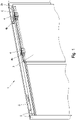
- FIG 1 shows a schematic representation of a shower cubicle sliding door system 1 according to the invention.
- the shower cubicle sliding door system 1 comprises a frame construction 2 for the suspension and guidance of at least one shower cubicle sliding door 3, at least one shower cubicle sliding door 3, and at least two guide devices 4, which are fixed at a distance from one another at an upper end of the shower cubicle sliding door 3, wherein each guide device 4 has at least one rotatably mounted roller 4b.
- the frame construction 2 has at least one guide channel 2a for guiding the rollers 4b, and the rollers 4b are set up to engage in this guide channel 2a and thereby allow the shower cubicle sliding door 3 to be displaced in relation to the frame construction 2.
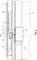
- the shower cubicle sliding door system 1 also comprises at least one damped closing device 5 firmly connected to the frame structure 2, the damped closing device 5 having a driver 5a with a first engagement section 5a' and a clamping means 5a" and a damping device 5b with a rod 5b' which is mounted in a damped manner so that it can be displaced along a displacement axis x.
- the driver 5a is connected to the rod 5b' and can be displaced together with the rod 5b'.
- the damped closing device has a clamping device 5c, the displaceability of the driver 5a along the displacement axis x between a release position P1 (see 3 ) and an end position P2 (see also figure 1 and 2 ) is limited, wherein between the release position P1 and the end position P2 a damping working area is formed by the damping device 5b, which extends to the end position P2.
- the clamping means 5c is set up to exert a force on the driver 5a, this force in the direction of the end position P2 opposite to the direction of the arrow in FIG 3 works.
- the end position P2 can be limited, for example, by a mechanical stop, which can be formed, for example, in the damper 5b.
- the driver 5a is mounted so that it can pivot in relation to the rod 5b' in order to switch between a driving position L2 (see 2 ) and a release position L1 (see 3 ) to be pivoted, wherein the locking device 5 also has a guide slot 5d, with the driver 5a is guided to change between driving position L2 and release position L1.
- the guide link 5d is designed in such a way that the driver 5a is rotated in relation to the rod 5b' when transferring to the release position P1, starting from the driver position L2 and into the release position L1, with the clamping means 5a" of the driver 5a being in the release position L1 with the locking device 5 is engaged in such a way that the driver 5a is held clamped against the force of the clamping device 5c on the locking device 5.
- the clamping device 5a" is guided in the guide slot 5d - for example in the form of a pin which is guided in a groove is, through which the guide slot 5d is formed.
- a second engagement section 4a' is provided on at least one of the at least two guide devices 4 for mechanical engagement in the first engagement section 5a', with the mechanical coupling of the two engagement sections 4a', 5a' being set up such that, starting from a position in which the driver 5a is in the release position L1, when approaching (against the direction of the arrow according to 3 ) of the second engagement portion 4a 'towards the driver 5a of the driver 5a by engaging in the second engagement section 4a' is pivoted into the driving position L2, in which the clamping means 5a" is released from a clamping position and the shower cubicle sliding door 3 can be moved to the end position P2 by means of the driver 5a due to the force of the clamping means 5c against the damping force of the damping device.
- the mechanical coupling of the two engagement sections 4a', 5a' is also set up so that, starting from a position in which the driver is in the driving position L2 and the two engagement sections 4a', 5a' engage in one another, the shower cubicle sliding door 3 together with the Driver 5a can be displaced counter to the force of the clamping means 5c towards the release position P1, with the driver 5a being guided back into the release position L1 when it reaches the release position P1 by being guided in the guide slot 5d, with a further displacement movement pointing away from the end position P2 in the release position L1 release the shower cubicle sliding door 3 and thus the position of the driver 5a is decoupled from the position of the second engagement section 4a'.
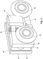
- each guide device 4 can also be made for each guide device 4 to have two rollers 4b and a metal support body 4c, with the rollers 4b being rotatably mounted on the support body 4c and the second engagement section 5a′ in the form of the projection protruding from the support body 4c.
- each guide device 4 has two clamps 4d that can be connected to one another, with a section of the shower cubicle sliding door 3 being framed by these clamps 4d, with a shaft 4e, which is oriented vertically in the assembled state, being formed on one of the two clamps 4d in each case.
- the supporting body 4c being fastened to the shaft 4e and being pivotable together with the rollers 4b in relation to the brackets 4d.
- the shaft 4e is formed by a threaded portion of a screw held in the supporting body 4c.
- Each clamp 4d in turn consists of a metal outer shell 4d' and a plastic carrier body 4d'' accommodated within the metal outer shell 4d'.
- the shower cubicle sliding door system 1 has a damped closing device 5 which is firmly connected to the frame construction 2 and which is arranged on the frame construction 2 in such a way that the shower cubicle sliding door 3 can be closed in a damped manner.
- the shower cubicle sliding door system 1 has a damped closing device 5 which is firmly connected to the frame construction 2 and which is arranged on the frame construction 2 in such a way that the shower cubicle sliding door 3 can reach a maximum opening position in a damped manner.
Landscapes
- Engineering & Computer Science (AREA)
- Mechanical Engineering (AREA)
- Health & Medical Sciences (AREA)
- Public Health (AREA)
- Epidemiology (AREA)
- General Health & Medical Sciences (AREA)
- Residential Or Office Buildings (AREA)
- Support Devices For Sliding Doors (AREA)
Description
- Die Erfindung betrifft ein Duschkabinenschiebetürsystem mit den Merkmalen des Anspruchs 1. Das Duschkabinenschiebetürsystem umfasst:
- eine Rahmenkonstruktion zur Aufhängung und Führung zumindest einer Duschkabinenschiebetür,
- zumindest eine Duschkabinenschiebetür, und
- zumindest zwei Führungsvorrichtungen, die an einem oberen Ende der Duschkabinenschiebetür zueinander beabstandet befestigt sind, wobei jede Führungsvorrichtung zumindest eine drehbar gelagerte Rolle aufweist,
wobei die Rahmenkonstruktion zumindest einen Führungskanal zur Führung der Rollen aufweist, und die Rollen dazu eingerichtet sind, in diesen Führungskanal einzugreifen und dadurch eine Verschiebung der Duschkabinenschiebetür in Bezug auf die Rahmenkonstruktion zu ermöglichen. - Das Duschkabinenschiebetürsystem weist ferner auf
- zumindest eine mit der Rahmenkonstruktion fest verbundene gedämpfte Schließeinrichtung, wobei die gedämpfte Schließeinrichtung
- einen Mitnehmer mit
- o einem ersten Eingriffsabschnitt und
- o einem Klemmmittel,
- eine Dämpfungsvorrichtung mit einer entlang einer Verschubachse gedämpft verschiebbar gelagerten Stange, wobei der Mitnehmer mit der Stange verbunden und mitsamt der Stange verschiebbar ist, und
- ein Spannmittel aufweist,
- einen Mitnehmer mit
- wobei der Mitnehmer in Bezug auf die Stange verschwenkbar gelagert ist, um zwischen einer Mitnahmelage und einer Freigabelage verschwenkt zu werden, wobei die Schließeinrichtung ferner eine Führungskulisse aufweist, mit der Mitnehmer zum Wechsel zwischen Mitnahmelage und Freigabelage geführt ist, wobei die Führungskulisse dergestalt ausgebildet ist, dass der Mitnehmer beim Überführen in die Freigabeposition in Bezug auf die Stange ausgehend von der Mitnahmelage in die Freigabelage gedreht wird, wobei in der Freigabelage das Klemmmittel des Mitnehmers mit der Schließeinrichtung dergestalt in Eingriff steht, dass der Mitnehmer entgegen der Kraft des Spannmittels an der Schließeinrichtung klemmend gehalten wird,
- wobei an zumindest einer der zumindest zwei Führungsvorrichtungen ein zum mechanischen Eingriff in den ersten Eingriffsabschnitt ausgebildeter zweiter Eingriffsabschnitt vorgesehen ist, wobei die mechanische Kopplung der beiden Eingriffsabschnitte dazu eingerichtet ist, dass sich ausgehend von einer Position, in der sich der Mitnehmer in der Freigabelage befindet, bei Heranführen des zweiten Eingriffsabschnitts hin zu dem Mitnehmer der Mitnehmer durch Eingriff in den zweiten Eingriffsabschnitt in die Mitnahmelage geschwenkt wird,in der das Klemmmittel von einer klemmenden Position gelöst und die Duschkabinenschiebetür mittels dem Mitnehmer aufgrund der Kraftwirkung des Spannmittels entgegen der Dämpfungskraft der Dämpfungsvorrichtung in die Endposition übergeführt werden kann, und
- wobei die mechanische Kopplung der beiden Eingriffsabschnitte ferner dazu eingerichtet ist, dass sich ausgehend von einer Position, in der sich der Mitnehmer in der Mitnahmelage befindet und die beiden Eingriffsabschnitte ineinander eingreifen, die Duschkabinenschiebetür mitsamt dem Mitnehmer entgegen der Kraftwirkung des Spannmittels hin zur Freigabeposition verschiebbar ist, wobei der Mitnehmer bei Erreichen der Freigabeposition durch Führung in der Führungskulisse in die Freigabelage rückgeführt wird, wobei in der Freigabelage eine weitere von der Endposition wegweisende Verschiebebewegung der Duschkabinenschiebetür freigeben und damit die Position des Mitnehmers von der Position des zweiten Eingriffsabschnittes entkoppelt wird, wobei jede Führungsvorrichtung zwei Rollen und einen metallischen Tragekörper aufweist, wobei die Rollen an dem Tragekörper drehbar gelagert sind und der zweite Eingriffsabschnitt in Form des Vorsprungs von dem Tragekörper absteht und wobei jede Führungsvorrichtung zwei miteinander verbindbaren Schellen aufweist, wobei ein Abschnitt der Duschkabinenschiebetür durch diese Schellen eingefasst ist.
- Weiters betrifft die Erfindung eine Duschkabine umfassend ein erfindungsgemäßes Duschkabinenschiebetürsystem.
- Duschkabinen mit Schiebetüren sind seit Jahrzehnten handelsüblich. Die Schiebetüren sind dabei üblicherweise über Rollen an einer Rahmenkonstruktion verschiebbar gelagert. Die Endpositionen der Schiebetüren werden durch Anschläge begrenzt, wobei das Erreichen der Endpositionen beispielsweise durch Aufeinandertreffen von Dichtungslippen gedämpft werden kann.
- Die Dokumente
DE 20 2013 100200 U1 undEP 2 617 336 A2 offenbaren Duschkabinenschiebetürsysteme nach dem Oberbegriff des Anspruchs 1. - Weiterhin offenbaren die
US 2015/033502 A1 undGB 2 535 441 A - Eine Aufgabe der Erfindung besteht daher darin eine Duschkabinenschiebetürsystem zu schaffen, welches die Nachteile des Standes der Technik überwindet. Diese Aufgabe wird mit einem Duschkabinenschiebetürsystem eingangs genannter Art gelöst, wobei auf einer der jeweils zwei Schellen eine im montierten Zustand vertikal orientierte Welle ausgebildet ist, wobei der Tragekörper an der Welle befestigt und mitsamt den Rollen in Bezug auf die Schellen verschwenkbar ist, und wobei die Welle durch einen Gewindeabschnitt einer Schraube ausgebildet ist, die im Tragekörper gehalten ist.
- Die jeweilige Schiebetür des Systems wird bei Annäherung in die Endposition automatisch und kontrolliert hin zur Endposition geführt.
- Die Führung erfolgt dabei rein mechanisch bzw. gegebenenfalls unter Verwendung hydraulischer Dämpfungsmittel und ohne Einsatz von elektrischer Energie. Durch diese Ausgestaltung des Duschkabinenschiebetürsystems wird eine kostengünstige und gleichzeitig robuste automatisierte gedämpfte Führungseinrichtung in einem Duschkabinenschiebetürsystem geschaffen.
- Insbesondere kann vorgesehen sein, dass der zweite Eingriffsabschnitt als Vorsprung und der erste Eingriffsabschnitt als dazu korrespondierende Vertiefung ausgebildet ist.
- Insbesondere kann vorgesehen sein, dass der Tragekörper aus verchromtem Messing besteht.
- Weiters kann vorgesehen sein, dass jede Schelle wiederum aus einer Metallaußenschale und innerhalb der Metallaußenschale aufgenommen Kunststoffträgerkörper besteht.
- Insbesondere kann vorgesehen sein, dass das Duschkabinenschiebetürsystem eine mit der Rahmenkonstruktion fest verbundene gedämpfte Schließeinrichtung aufweist, die dergestalt an der Rahmenkonstruktion angeordnet ist, dass dadurch ein Verschließen der Duschkabinenschiebetür gedämpft herbeiführbar ist.
- Weiters kann vorgesehen sein, dass das Duschkabinenschiebetürsystem eine mit der Rahmenkonstruktion fest verbundene gedämpfte Schließeinrichtung aufweist, die dergestalt an der Rahmenkonstruktion angeordnet ist, dass dadurch das Erreichen einer maximalen Öffnungsposition der Duschkabinenschiebetür gedämpft herbeiführbar ist.
- Insbesondere kann vorgesehen sein, dass die Duschkabinenschiebetür eben ausgebildet ist. Die Erfindung betrifft weiters eine Duschkabine umfassend ein erfindungsgemäßes Duschkabinenschiebetürsystem.
- Die Erfindung ist im Folgenden anhand einer beispielhaften und nicht einschränkenden Ausführungsform näher erläutert, die in den Figuren veranschaulicht ist. Darin zeigt
- Figur 1
- eine schematische Darstellung eines erfindungsgemäßen Duschkabinenschiebetürsystems,
- Figur 2
- eine detaillierte Darstellung einer Führungsvorrichtung sowie einer Schließeinrichtung des Duschkabinensystems gemäß
Fig. 1 in einer Schließposition P2, - Figur 3
- eine detaillierte Darstellung der Führungsvorrichtung sowie einer Schließeinrichtung des Duschkabinensystems gemäß
Fig. 1 in einer Freigabeposition P1, - Figur 4
- eine perspektivische Darstellung einer Führungsvorrichtung gemäß
Fig. 2 und3 , und - Figur 5
- eine Schnittdarstellung der Führungsvorrichtung sowie einer Schließeinrichtung des Duschkabinensystems gemäß
Fig. 1 . - In den folgenden Figuren bezeichnen - sofern nicht anders angegeben - gleiche Bezugszeichen gleiche Merkmale.
-
Figur 1 zeigt eine schematische Darstellung eines erfindungsgemäßen Duschkabinenschiebetürsystems 1. Das Duschkabinenschiebetürsystem 1 umfasst eine Rahmenkonstruktion 2 zur Aufhängung und Führung zumindest einer Duschkabinenschiebetür 3, zumindest eine Duschkabinenschiebetür 3, und zumindest zwei Führungsvorrichtungen 4, die an einem oberen Ende der Duschkabinenschiebetür 3 zueinander beabstandet befestigt sind, wobei jede Führungsvorrichtung 4 zumindest eine drehbar gelagerte Rolle 4b aufweist. - Die Rahmenkonstruktion 2 weist zumindest einen Führungskanal 2a zur Führung der Rollen 4b auf, und die Rollen 4b sind dazu eingerichtet, in diesen Führungskanal 2a einzugreifen und dadurch eine Verschiebung der Duschkabinenschiebetür 3 in Bezug auf die Rahmenkonstruktion 2 zu ermöglichen.
- Das Duschkabinenschiebetürsystem 1 umfasst ferner zumindest eine mit der Rahmenkonstruktion 2 fest verbundene gedämpfte Schließeinrichtung 5, wobei die gedämpfte Schließeinrichtung 5 einen Mitnehmer 5a mit einem ersten Eingriffsabschnitt 5a' und einem Klemmmittel 5a" sowie eine Dämpfungsvorrichtung 5b mit einer entlang einer Verschubachse x gedämpft verschiebbar gelagerten Stange 5b' aufweist. Der Mitnehmer 5a ist mit der Stange 5b' verbunden und mitsamt der Stange 5b' verschiebbar.
- Die gedämpfte Schließeinrichtung weist ein Spannmittel 5c auf, wobei die Verschiebbarkeit des Mitnehmers 5a entlang der Verschubachse x zwischen einer Freigabeposition P1 (siehe
Fig. 3 ) und einer Endpositionen P2 (siehe auchFig 1 und2 ) begrenzt ist, wobei zwischen der Freigabeposition P1 und Endposition P2 durch die Dämpfungsvorrichtung 5b ein Dämpfungsarbeitsbereich ausgebildet ist, der sich bis zur Endposition P2 erstreckt. Das Spannmittel 5c ist dazu eingerichtet, eine Kraft auf den Mitnehmer 5a auszuüben, wobei diese Kraft in Richtung der Endposition P2 entgegen der Pfeilrichtung inFig. 3 wirkt. Die Endposition P2 kann beispielsweise durch einen mechanischen Anschlag begrenzt sein, der z.B. im Dämpfer 5b ausgebildet sein kann. - Der Mitnehmer 5a ist in Bezug auf die Stange 5b' verschwenkbar gelagert, um zwischen einer Mitnahmelage L2 (siehe
Fig. 2 ) und einer Freigabelage L1 (sieheFig. 3 ) verschwenkt zu werden, wobei die Schließeinrichtung 5 ferner eine Führungskulisse 5d aufweist, mit der Mitnehmer 5a zum Wechsel zwischen Mitnahmelage L2 und Freigabelage L1 geführt ist. - Die Führungskulisse 5d ist dergestalt ausgebildet, dass der Mitnehmer 5a beim Überführen in die Freigabeposition P1 in Bezug auf die Stange 5b' ausgehend von der Mitnahmelage L2 in die Freigabelage L1 gedreht wird, wobei in der Freigabelage L1 das Klemmmittel 5a" des Mitnehmers 5a mit der Schließeinrichtung 5 dergestalt in Eingriff steht, dass der Mitnehmer 5a entgegen der Kraft des Spannmittels 5c an der Schließeinrichtung 5 klemmend gehalten wird. Zu diesem Zweck ist das Klemmmittel 5a" in der Führungskulisse 5d geführt - beispielsweise in Form eines Zapfens, der in einer Nut geführt wird, durch die die Führungskulisse 5d ausgebildet wird.
- An zumindest einer der zumindest zwei Führungsvorrichtungen 4 ist zum mechanischen Eingriff in den ersten Eingriffsabschnitt 5a' ein zweiter Eingriffsabschnitt 4a' vorgesehen, wobei die mechanische Kopplung der beiden Eingriffsabschnitte 4a', 5a' dazu eingerichtet ist, dass sich ausgehend von einer Position, in der sich der Mitnehmer 5a in der Freigabelage L1 befindet, bei Heranführen (entgegen der Pfeilrichtung gemäß
Fig. 3 ) des zweiten Eingriffsabschnitts 4a' hin zu dem Mitnehmer 5a der Mitnehmer 5a durch Eingriff in den zweiten Eingriffsabschnitt 4a' in die Mitnahmelage L2 geschwenkt wird, in der das Klemmmittel 5a" von einer klemmenden Position gelöst und die Duschkabinenschiebetür 3 mittels dem Mitnehmer 5a aufgrund der Kraftwirkung des Spannmittels 5c entgegen der Dämpfungskraft der Dämpfungsvorrichtung in die Endposition P2 übergeführt werden kann. - Die mechanische Kopplung der beiden Eingriffsabschnitte 4a', 5a' ist ferner dazu eingerichtet, dass sich ausgehend von einer Position, in der sich der Mitnehmer in der Mitnahmelage L2 befindet und die beiden Eingriffsabschnitte 4a', 5a' ineinander eingreifen, die Duschkabinenschiebetür 3 mitsamt dem Mitnehmer 5a entgegen der Kraftwirkung des Spannmittels 5c hin zur Freigabeposition P1 verschiebbar ist, wobei der Mitnehmer 5a bei Erreichen der Freigabeposition P1 durch Führung in der Führungskulisse 5d in die Freigabelage L1 rückgeführt wird, wobei in der Freigabelage L1 eine weitere von der Endposition P2 wegweisende Verschiebebewegung der Duschkabinenschiebetür 3 freigeben und damit die Position des Mitnehmers 5a von der Position des zweiten Eingriffsabschnittes 4a' entkoppelt wird.
- Zudem kann vorgesehen sein, dass der zweite Eingriffsabschnitt 4a' als Vorsprung und der erste Eingriffsabschnitt 5a' als dazu korrespondierende Vertiefung ausgebildet ist.
- Weiters kann vorgesehen sein, dass jede Führungsvorrichtung 4 zwei Rollen 4b und einen metallischen Tragekörper 4c aufweist, wobei die Rollen 4b an dem Tragekörper 4c drehbar gelagert sind und der zweite Eingriffsabschnitt 5a' in Form des Vorsprungs von dem Tragekörper 4c absteht.
- In der gezeigten Ausführungsform ist vorgesehen, dass jede Führungsvorrichtung 4 zwei miteinander verbindbaren Schellen 4d aufweist, wobei ein Abschnitt der Duschkabinenschiebetür 3 durch diese Schellen 4d eingefasst ist, wobei auf einer der jeweils zwei Schellen 4d eine im montierten Zustand vertikal orientierte Welle 4e ausgebildet ist, wobei der Tragekörper 4c an der Welle 4e befestigt und mitsamt den Rollen 4b in Bezug auf die Schellen 4d verschwenkbar ist. Dabei ist die Welle 4e durch Gewindeabschnitt einer Schraube ausgebildet, die im Tragekörper 4c gehalten ist. Jede Schelle 4d besteht wiederum aus einer Metallaußenschale 4d' und innerhalb der Metallaußenschale 4d' aufgenommen Kunststoffträgerkörper 4d".
- Das Duschkabinenschiebetürsystem 1 weist eine mit der Rahmenkonstruktion 2 fest verbundene gedämpfte Schließeinrichtung 5 auf, die dergestalt an der Rahmenkonstruktion 2 angeordnet ist, dass dadurch ein Verschließen der Duschkabinenschiebetür 3 gedämpft herbeiführbar ist.
- Das Duschkabinenschiebetürsystem 1 weist eine mit der Rahmenkonstruktion 2 fest verbundene gedämpfte Schließeinrichtung 5 aufweist, die dergestalt an der Rahmenkonstruktion 2 angeordnet ist, dass dadurch das Erreichen einer maximalen Öffnungsposition der Duschkabinenschiebetür 3 gedämpft herbeiführbar ist.
- In Anbetracht dieser Lehre ist der Fachmann in der Lage, ohne erfinderisches Zutun zu anderen, nicht gezeigten Ausführungsformen der Erfindung zu gelangen. Die Erfindung ist daher nicht auf die gezeigte Ausführungsform beschränkt, sondern durch den gesamten Schutzumfang der Ansprüche definiert. Auch können einzelne Aspekte der Erfindung bzw. der Ausführungsform aufgegriffen und miteinander kombiniert werden. Etwaige Bezugszeichen in den Ansprüchen sind beispielhaft und dienen nur der einfacheren Lesbarkeit der Ansprüche, ohne diese einzuschränken.
Claims (8)
- Duschkabinenschiebetürsystem (1) umfassend- eine Rahmenkonstruktion (2) zur Aufhängung und Führung zumindest einer Duschkabinenschiebetür (3),- zumindest eine Duschkabinenschiebetür (3), und- zumindest zwei Führungsvorrichtungen (4), die an einem oberen Ende der Duschkabinenschiebetür (3) zueinander beabstandet befestigt sind, wobei jede Führungsvorrichtung (4) zumindest eine drehbar gelagerte Rolle (4b) aufweist,wobei die Rahmenkonstruktion (2) zumindest einen Führungskanal (2a) zur Führung der Rollen (4b) aufweist, und die Rollen (4b) dazu eingerichtet sind, in diesen Führungskanal (2a) einzugreifen und dadurch eine Verschiebung der Duschkabinenschiebetür (3) in Bezug auf die Rahmenkonstruktion (2) zu ermöglichen,
wobei das Duschkabinenschiebetürsystem (1) ferner- zumindest eine mit der Rahmenkonstruktion (2) fest verbundene gedämpfte Schließeinrichtung (5) aufweist, wobei die gedämpfte Schließeinrichtung (5)wobei die Verschiebbarkeit des Mitnehmers (5a) entlang der Verschubachse (x) zwischen einer Freigabeposition (P1) und einer Endpositionen (P2) begrenzt ist, wobei zwischen der Freigabeposition (P1) und Endposition (P2) durch die Dämpfungsvorrichtung (5b) ein Dämpfungsarbeitsbereich ausgebildet ist, der sich bis zur Endposition erstreckt, wobei das Spannmittel (5c) dazu eingerichtet ist, eine Kraft auf den Mitnehmer (5a) auszuüben, wobei diese Kraft in Richtung der Endposition (P2) wirkt,• einen Mitnehmer (5a) mito einem ersten Eingriffsabschnitt (5a') undo einem Klemmmittel (5a"),• eine Dämpfungsvorrichtung (5b) mit einer entlang einer Verschubachse (x) gedämpft verschiebbar gelagerten Stange (5b'), wobei der Mitnehmer (5a) mit der Stange (5b') verbunden und mitsamt der Stange (5b') verschiebbar ist, und• ein Spannmittel (5c) aufweist,wobei der Mitnehmer (5a) in Bezug auf die Stange (5b') verschwenkbar gelagert ist, um zwischen einer Mitnahmelage (L2) und einer Freigabelage (L1) verschwenkt zu werden, wobei die Schließeinrichtung (5) ferner eine Führungskulisse (5d) aufweist, mit der Mitnehmer (5a) zum Wechsel zwischen Mitnahmelage (L2) und Freigabelage (L1) geführt ist, wobei die Führungskulisse (5d) dergestalt ausgebildet ist, dass der Mitnehmer (5a) beim Überführen in die Freigabeposition (P1) in Bezug auf die Stange (5b') ausgehend von der Mitnahmelage (L2) in die Freigabelage (L1) gedreht wird, wobei in der Freigabelage (L1) das Klemmmittel (5a") des Mitnehmers (5a) mit der Schließeinrichtung (5) dergestalt in Eingriff steht, dass der Mitnehmer (5a) entgegen der Kraft des Spannmittels (5c) an der Schließeinrichtung (5) klemmend gehalten wird,wobei an zumindest einer der zumindest zwei Führungsvorrichtungen (4) ein zum mechanischen Eingriff in den ersten Eingriffsabschnitt (5a') ausgebildeter zweiter Eingriffsabschnitt (4a') vorgesehen ist, wobei die mechanische Kopplung der beiden Eingriffsabschnitte (4a', 5a') dazu eingerichtet ist, dass sich ausgehend von einer Position, in der sich der Mitnehmer (5a) in der Freigabelage (L1) befindet, bei Heranführen des zweiten Eingriffsabschnitts (4a') hin zu dem Mitnehmer (5a) der Mitnehmer (5a) durch Eingriff in den zweiten Eingriffsabschnitt (4a') in die Mitnahmelage (L2) geschwenkt wird, in der das Klemmmittel (5a") von einer klemmenden Position gelöst und die Duschkabinenschiebetür (3) mittels dem Mitnehmer (5a) aufgrund der Kraftwirkung des Spannmittels (5c) entgegen der Dämpfungskraft der Dämpfungsvorrichtung in die Endposition (P2) übergeführt werden kann, undwobei die mechanische Kopplung der beiden Eingriffsabschnitte (4a', 5a') ferner dazu eingerichtet ist, dass sich ausgehend von einer Position, in der sich der Mitnehmer in der Mitnahmelage (L2) befindet und die beiden Eingriffsabschnitte (4a', 5a') ineinander eingreifen, die Duschkabinenschiebetür (3) mitsamt dem Mitnehmer (5a) entgegen der Kraftwirkung des Spannmittels (5c) hin zur Freigabeposition (P1) verschiebbar ist, wobei der Mitnehmer (5a) bei Erreichen der Freigabeposition (P1) durch Führung in der Führungskulisse (5d) in die Freigabelage (L1) rückgeführt wird, wobei in der Freigabelage (L1) eine weitere von der Endposition (P2) wegweisende Verschiebebewegung der Duschkabinenschiebetür (3) freigeben und damit die Position des Mitnehmers (5a) von der Position des zweiten Eingriffsabschnittes (4a') entkoppelt wird, wobei jede Führungsvorrichtung (4) zwei Rollen (4b) und einen metallischen Tragekörper (4c) aufweist, wobei die Rollen (4b) an dem Tragekörper (4c) drehbar gelagert sind und der zweite Eingriffsabschnitt (5a') in Form des Vorsprungs von dem Tragekörper (4c) absteht, wobei jede Führungsvorrichtung (4) zwei miteinander verbindbare Schellen (4d) aufweist, wobei ein Abschnitt der Duschkabinenschiebetür (3) durch diese Schellen (4d) eingefasst ist,dadurch gekennzeichnet, dassauf einer der jeweils zwei Schellen (4d) eine im montierten Zustand vertikal orientierte Welle (4e) ausgebildet ist, wobei der Tragekörper (4c) an der Welle (4e) befestigt und mitsamt den Rollen (4b) in Bezug auf die Schellen (4d) verschwenkbar ist, wobei die Welle (4e) durch einen Gewindeabschnitt einer Schraube ausgebildet ist, die im Tragekörper (4c) gehalten ist. - Duschkabinenschiebetürsystem (1) nach Anspruch 1, wobei der zweite Eingriffsabschnitt (4a') als Vorsprung und der erste Eingriffsabschnitt (5a') als dazu korrespondierende Vertiefung ausgebildet ist.
- Duschkabinenschiebetürsystem (1) nach Anspruch 1 oder 2, wobei der Tragekörper (4c) aus verchromtem Messing besteht.
- Duschkabinenschiebetürsystem (1) nach einem der vorhergehenden Ansprüche, wobei jede Schelle (4d) wiederum aus einer Metallaußenschale (4d') und innerhalb der Metallaußenschale (4d') aufgenommen Kunststoffträgerkörper (4d") besteht.
- Duschkabinenschiebetürsystem (1) nach einem der vorhergehenden Ansprüche, wobei das Duschkabinenschiebetürsystem (1) eine mit der Rahmenkonstruktion (2) fest verbundene gedämpfte Schließeinrichtung (5) aufweist, die dergestalt an der Rahmenkonstruktion (2) angeordnet ist, dass dadurch ein Verschließen der Duschkabinenschiebetür (3) gedämpft herbeiführbar ist.
- Duschkabinenschiebetürsystem (1) nach einem der vorhergehenden Ansprüche, wobei das Duschkabinenschiebetürsystem (1) eine mit der Rahmenkonstruktion (2) fest verbundene gedämpfte Schließeinrichtung (5) aufweist, die dergestalt an der Rahmenkonstruktion (2) angeordnet ist, dass dadurch das Erreichen einer maximalen Öffnungsposition der Duschkabinenschiebetür (3) gedämpft herbeiführbar ist.
- Duschkabinenschiebetürsystem (1) nach einem der vorhergehenden Ansprüche, wobei die Duschkabinenschiebetür (3) eben ausgebildet ist.
- Duschkabine, umfassend ein Duschkabinenschiebetürsystem (1) nach einem der vorhergehenden Ansprüche.
Priority Applications (1)
| Application Number | Priority Date | Filing Date | Title |
|---|---|---|---|
| EP20152871.8A EP3854974B1 (de) | 2020-01-21 | 2020-01-21 | Duschkabinenschiebetürsystem |
Applications Claiming Priority (1)
| Application Number | Priority Date | Filing Date | Title |
|---|---|---|---|
| EP20152871.8A EP3854974B1 (de) | 2020-01-21 | 2020-01-21 | Duschkabinenschiebetürsystem |
Publications (2)
| Publication Number | Publication Date |
|---|---|
| EP3854974A1 EP3854974A1 (de) | 2021-07-28 |
| EP3854974B1 true EP3854974B1 (de) | 2022-09-07 |
Family
ID=69185505
Family Applications (1)
| Application Number | Title | Priority Date | Filing Date |
|---|---|---|---|
| EP20152871.8A Active EP3854974B1 (de) | 2020-01-21 | 2020-01-21 | Duschkabinenschiebetürsystem |
Country Status (1)
| Country | Link |
|---|---|
| EP (1) | EP3854974B1 (de) |
Citations (7)
| Publication number | Priority date | Publication date | Assignee | Title |
|---|---|---|---|---|
| EP0956799A2 (de) | 1998-05-13 | 1999-11-17 | DORMA GmbH + Co. KG | Duschabtrennung |
| DE19914319A1 (de) | 1999-03-29 | 2000-10-12 | Dorma Gmbh & Co Kg | Duschabtrennung |
| DE202013100200U1 (de) | 2013-01-15 | 2013-01-25 | Ideal Sanitary Ware Co., Ltd. | Eine Duschtür mit verborgenen Puffervorrichtungen |
| EP2617336A2 (de) | 2012-01-20 | 2013-07-24 | Schulte Duschkabinenbau GmbH & Co. KG | Duschabtrennung |
| DE202013007992U1 (de) | 2013-07-30 | 2013-10-15 | Foshan Ideal Co., Ltd | Duschtür-Baugruppe mit selbstschließender Funktion |
| US20150033502A1 (en) | 2013-07-30 | 2015-02-05 | Ideal Sanitary Ware Co., Ltd. | Pulley mechanism |
| GB2535441A (en) | 2015-01-08 | 2016-08-24 | Lorenzo Darren | Adjustable runner apparatus |
-
2020
- 2020-01-21 EP EP20152871.8A patent/EP3854974B1/de active Active
Patent Citations (7)
| Publication number | Priority date | Publication date | Assignee | Title |
|---|---|---|---|---|
| EP0956799A2 (de) | 1998-05-13 | 1999-11-17 | DORMA GmbH + Co. KG | Duschabtrennung |
| DE19914319A1 (de) | 1999-03-29 | 2000-10-12 | Dorma Gmbh & Co Kg | Duschabtrennung |
| EP2617336A2 (de) | 2012-01-20 | 2013-07-24 | Schulte Duschkabinenbau GmbH & Co. KG | Duschabtrennung |
| DE202013100200U1 (de) | 2013-01-15 | 2013-01-25 | Ideal Sanitary Ware Co., Ltd. | Eine Duschtür mit verborgenen Puffervorrichtungen |
| DE202013007992U1 (de) | 2013-07-30 | 2013-10-15 | Foshan Ideal Co., Ltd | Duschtür-Baugruppe mit selbstschließender Funktion |
| US20150033502A1 (en) | 2013-07-30 | 2015-02-05 | Ideal Sanitary Ware Co., Ltd. | Pulley mechanism |
| GB2535441A (en) | 2015-01-08 | 2016-08-24 | Lorenzo Darren | Adjustable runner apparatus |
Also Published As
| Publication number | Publication date |
|---|---|
| EP3854974A1 (de) | 2021-07-28 |
Similar Documents
| Publication | Publication Date | Title |
|---|---|---|
| DE69001041T2 (de) | Moebelscharnier, insbesondere mit scharniertopf. | |
| DE102017113862B3 (de) | Endlagedämpfungsvorrichtung und Anordnung mit einer Endlagedämpfungsvorrichtung | |
| DE102008022096A1 (de) | Stangeneinstellklemme für Fahrzeugtür | |
| EP3625415B1 (de) | Klappenlager mit einer einstellhilfe | |
| WO2020236100A1 (de) | Möbelbeschlag | |
| EP3580418A1 (de) | Einfach zu montierendes möbelscharnier | |
| EP3050413B1 (de) | Lüftereinrichtung | |
| EP2180121B1 (de) | Vorrichtung zur Festlegung der Lage einer Klappe | |
| EP3511499B1 (de) | Vorrichtung zur schwenkbaren befestigung eines türflügels an einer türzarge | |
| DE102013104420A1 (de) | Führungsanordnung einer Schiebetür, Schiebetür und Möbel | |
| EP2672045B1 (de) | Führungsanordnung einer Schiebetür eines Schiebetürmöbels | |
| EP3854974B1 (de) | Duschkabinenschiebetürsystem | |
| EP3251571A1 (de) | Scharnier zur verschwenkung einer tür | |
| DE2530199A1 (de) | Halterung zum befestigen eines geraetes der nachrichtentechnik | |
| DE69402940T2 (de) | Türhalter mit wählbarer Reibungsunterstützung | |
| DE69400735T2 (de) | Vorrichtung zum Anbringen von Dichtungen | |
| DE102005002759A1 (de) | Schlittenbaugruppe für einen Fensterheber, insbesondere für Fahrzeuge | |
| DE4400249C1 (de) | Wandinstallationskanal für Elektroinstallationseinrichtungen | |
| DE102020119523B4 (de) | Verfahren zur Installation eines Garagentors | |
| EP2636836A2 (de) | Schiebetüranordnung | |
| DE19700619B4 (de) | Gelenkband mit Schließkraftverstellung | |
| EP0619635B1 (de) | Sammelhalter für Kabel oder Rohre | |
| DE102012104863B3 (de) | Türbandanordnung mit einem Türband und einem Aufnahmeelement | |
| AT525709A1 (de) | Beschlag zur bewegbaren Lagerung eines Schwenkelements | |
| DE102020114807A1 (de) | Möbel |
Legal Events
| Date | Code | Title | Description |
|---|---|---|---|
| PUAI | Public reference made under article 153(3) epc to a published international application that has entered the european phase |
Free format text: ORIGINAL CODE: 0009012 |
|
| STAA | Information on the status of an ep patent application or granted ep patent |
Free format text: STATUS: THE APPLICATION HAS BEEN PUBLISHED |
|
| AK | Designated contracting states |
Kind code of ref document: A1 Designated state(s): AL AT BE BG CH CY CZ DE DK EE ES FI FR GB GR HR HU IE IS IT LI LT LU LV MC MK MT NL NO PL PT RO RS SE SI SK SM TR |
|
| STAA | Information on the status of an ep patent application or granted ep patent |
Free format text: STATUS: REQUEST FOR EXAMINATION WAS MADE |
|
| 17P | Request for examination filed |
Effective date: 20220125 |
|
| RBV | Designated contracting states (corrected) |
Designated state(s): AL AT BE BG CH CY CZ DE DK EE ES FI FR GB GR HR HU IE IS IT LI LT LU LV MC MK MT NL NO PL PT RO RS SE SI SK SM TR |
|
| GRAP | Despatch of communication of intention to grant a patent |
Free format text: ORIGINAL CODE: EPIDOSNIGR1 |
|
| STAA | Information on the status of an ep patent application or granted ep patent |
Free format text: STATUS: GRANT OF PATENT IS INTENDED |
|
| INTG | Intention to grant announced |
Effective date: 20220412 |
|
| GRAS | Grant fee paid |
Free format text: ORIGINAL CODE: EPIDOSNIGR3 |
|
| GRAA | (expected) grant |
Free format text: ORIGINAL CODE: 0009210 |
|
| STAA | Information on the status of an ep patent application or granted ep patent |
Free format text: STATUS: THE PATENT HAS BEEN GRANTED |
|
| AK | Designated contracting states |
Kind code of ref document: B1 Designated state(s): AL AT BE BG CH CY CZ DE DK EE ES FI FR GB GR HR HU IE IS IT LI LT LU LV MC MK MT NL NO PL PT RO RS SE SI SK SM TR |
|
| REG | Reference to a national code |
Ref country code: GB Ref legal event code: FG4D Free format text: NOT ENGLISH |
|
| REG | Reference to a national code |
Ref country code: CH Ref legal event code: EP Ref country code: AT Ref legal event code: REF Ref document number: 1517174 Country of ref document: AT Kind code of ref document: T Effective date: 20220915 |
|
| REG | Reference to a national code |
Ref country code: DE Ref legal event code: R096 Ref document number: 502020001627 Country of ref document: DE |
|
| REG | Reference to a national code |
Ref country code: IE Ref legal event code: FG4D Free format text: LANGUAGE OF EP DOCUMENT: GERMAN |
|
| REG | Reference to a national code |
Ref country code: LT Ref legal event code: MG9D |
|
| REG | Reference to a national code |
Ref country code: NL Ref legal event code: MP Effective date: 20220907 |
|
| PG25 | Lapsed in a contracting state [announced via postgrant information from national office to epo] |
Ref country code: SE Free format text: LAPSE BECAUSE OF FAILURE TO SUBMIT A TRANSLATION OF THE DESCRIPTION OR TO PAY THE FEE WITHIN THE PRESCRIBED TIME-LIMIT Effective date: 20220907 Ref country code: RS Free format text: LAPSE BECAUSE OF FAILURE TO SUBMIT A TRANSLATION OF THE DESCRIPTION OR TO PAY THE FEE WITHIN THE PRESCRIBED TIME-LIMIT Effective date: 20220907 Ref country code: NO Free format text: LAPSE BECAUSE OF FAILURE TO SUBMIT A TRANSLATION OF THE DESCRIPTION OR TO PAY THE FEE WITHIN THE PRESCRIBED TIME-LIMIT Effective date: 20221207 Ref country code: LV Free format text: LAPSE BECAUSE OF FAILURE TO SUBMIT A TRANSLATION OF THE DESCRIPTION OR TO PAY THE FEE WITHIN THE PRESCRIBED TIME-LIMIT Effective date: 20220907 Ref country code: LT Free format text: LAPSE BECAUSE OF FAILURE TO SUBMIT A TRANSLATION OF THE DESCRIPTION OR TO PAY THE FEE WITHIN THE PRESCRIBED TIME-LIMIT Effective date: 20220907 Ref country code: FI Free format text: LAPSE BECAUSE OF FAILURE TO SUBMIT A TRANSLATION OF THE DESCRIPTION OR TO PAY THE FEE WITHIN THE PRESCRIBED TIME-LIMIT Effective date: 20220907 |
|
| PG25 | Lapsed in a contracting state [announced via postgrant information from national office to epo] |
Ref country code: HR Free format text: LAPSE BECAUSE OF FAILURE TO SUBMIT A TRANSLATION OF THE DESCRIPTION OR TO PAY THE FEE WITHIN THE PRESCRIBED TIME-LIMIT Effective date: 20220907 Ref country code: GR Free format text: LAPSE BECAUSE OF FAILURE TO SUBMIT A TRANSLATION OF THE DESCRIPTION OR TO PAY THE FEE WITHIN THE PRESCRIBED TIME-LIMIT Effective date: 20221208 |
|
| PG25 | Lapsed in a contracting state [announced via postgrant information from national office to epo] |
Ref country code: SM Free format text: LAPSE BECAUSE OF FAILURE TO SUBMIT A TRANSLATION OF THE DESCRIPTION OR TO PAY THE FEE WITHIN THE PRESCRIBED TIME-LIMIT Effective date: 20220907 Ref country code: RO Free format text: LAPSE BECAUSE OF FAILURE TO SUBMIT A TRANSLATION OF THE DESCRIPTION OR TO PAY THE FEE WITHIN THE PRESCRIBED TIME-LIMIT Effective date: 20220907 Ref country code: PT Free format text: LAPSE BECAUSE OF FAILURE TO SUBMIT A TRANSLATION OF THE DESCRIPTION OR TO PAY THE FEE WITHIN THE PRESCRIBED TIME-LIMIT Effective date: 20230109 Ref country code: ES Free format text: LAPSE BECAUSE OF FAILURE TO SUBMIT A TRANSLATION OF THE DESCRIPTION OR TO PAY THE FEE WITHIN THE PRESCRIBED TIME-LIMIT Effective date: 20220907 Ref country code: CZ Free format text: LAPSE BECAUSE OF FAILURE TO SUBMIT A TRANSLATION OF THE DESCRIPTION OR TO PAY THE FEE WITHIN THE PRESCRIBED TIME-LIMIT Effective date: 20220907 |
|
| PG25 | Lapsed in a contracting state [announced via postgrant information from national office to epo] |
Ref country code: SK Free format text: LAPSE BECAUSE OF FAILURE TO SUBMIT A TRANSLATION OF THE DESCRIPTION OR TO PAY THE FEE WITHIN THE PRESCRIBED TIME-LIMIT Effective date: 20220907 Ref country code: PL Free format text: LAPSE BECAUSE OF FAILURE TO SUBMIT A TRANSLATION OF THE DESCRIPTION OR TO PAY THE FEE WITHIN THE PRESCRIBED TIME-LIMIT Effective date: 20220907 Ref country code: IS Free format text: LAPSE BECAUSE OF FAILURE TO SUBMIT A TRANSLATION OF THE DESCRIPTION OR TO PAY THE FEE WITHIN THE PRESCRIBED TIME-LIMIT Effective date: 20230107 Ref country code: EE Free format text: LAPSE BECAUSE OF FAILURE TO SUBMIT A TRANSLATION OF THE DESCRIPTION OR TO PAY THE FEE WITHIN THE PRESCRIBED TIME-LIMIT Effective date: 20220907 |
|
| REG | Reference to a national code |
Ref country code: DE Ref legal event code: R026 Ref document number: 502020001627 Country of ref document: DE |
|
| PLBI | Opposition filed |
Free format text: ORIGINAL CODE: 0009260 |
|
| P01 | Opt-out of the competence of the unified patent court (upc) registered |
Effective date: 20230524 |
|
| PLAX | Notice of opposition and request to file observation + time limit sent |
Free format text: ORIGINAL CODE: EPIDOSNOBS2 |
|
| PG25 | Lapsed in a contracting state [announced via postgrant information from national office to epo] |
Ref country code: NL Free format text: LAPSE BECAUSE OF FAILURE TO SUBMIT A TRANSLATION OF THE DESCRIPTION OR TO PAY THE FEE WITHIN THE PRESCRIBED TIME-LIMIT Effective date: 20220907 Ref country code: AL Free format text: LAPSE BECAUSE OF FAILURE TO SUBMIT A TRANSLATION OF THE DESCRIPTION OR TO PAY THE FEE WITHIN THE PRESCRIBED TIME-LIMIT Effective date: 20220907 |
|
| 26 | Opposition filed |
Opponent name: SCHULTE DUSCHKABINENBAU GMBH & CO. KG Effective date: 20230607 |
|
| PG25 | Lapsed in a contracting state [announced via postgrant information from national office to epo] |
Ref country code: DK Free format text: LAPSE BECAUSE OF FAILURE TO SUBMIT A TRANSLATION OF THE DESCRIPTION OR TO PAY THE FEE WITHIN THE PRESCRIBED TIME-LIMIT Effective date: 20220907 |
|
| PG25 | Lapsed in a contracting state [announced via postgrant information from national office to epo] |
Ref country code: SI Free format text: LAPSE BECAUSE OF FAILURE TO SUBMIT A TRANSLATION OF THE DESCRIPTION OR TO PAY THE FEE WITHIN THE PRESCRIBED TIME-LIMIT Effective date: 20220907 |
|
| REG | Reference to a national code |
Ref country code: CH Ref legal event code: PL |
|
| PG25 | Lapsed in a contracting state [announced via postgrant information from national office to epo] |
Ref country code: LU Free format text: LAPSE BECAUSE OF NON-PAYMENT OF DUE FEES Effective date: 20230121 |
|
| REG | Reference to a national code |
Ref country code: BE Ref legal event code: MM Effective date: 20230131 |
|
| PG25 | Lapsed in a contracting state [announced via postgrant information from national office to epo] |
Ref country code: LI Free format text: LAPSE BECAUSE OF NON-PAYMENT OF DUE FEES Effective date: 20230131 Ref country code: CH Free format text: LAPSE BECAUSE OF NON-PAYMENT OF DUE FEES Effective date: 20230131 |
|
| PLBB | Reply of patent proprietor to notice(s) of opposition received |
Free format text: ORIGINAL CODE: EPIDOSNOBS3 |
|
| PG25 | Lapsed in a contracting state [announced via postgrant information from national office to epo] |
Ref country code: FR Free format text: LAPSE BECAUSE OF NON-PAYMENT OF DUE FEES Effective date: 20230131 Ref country code: BE Free format text: LAPSE BECAUSE OF NON-PAYMENT OF DUE FEES Effective date: 20230131 |
|
| PG25 | Lapsed in a contracting state [announced via postgrant information from national office to epo] |
Ref country code: IE Free format text: LAPSE BECAUSE OF NON-PAYMENT OF DUE FEES Effective date: 20230121 |
|
| PG25 | Lapsed in a contracting state [announced via postgrant information from national office to epo] |
Ref country code: IT Free format text: LAPSE BECAUSE OF FAILURE TO SUBMIT A TRANSLATION OF THE DESCRIPTION OR TO PAY THE FEE WITHIN THE PRESCRIBED TIME-LIMIT Effective date: 20220907 |
|
| PG25 | Lapsed in a contracting state [announced via postgrant information from national office to epo] |
Ref country code: MC Free format text: LAPSE BECAUSE OF FAILURE TO SUBMIT A TRANSLATION OF THE DESCRIPTION OR TO PAY THE FEE WITHIN THE PRESCRIBED TIME-LIMIT Effective date: 20220907 |
|
| PG25 | Lapsed in a contracting state [announced via postgrant information from national office to epo] |
Ref country code: MC Free format text: LAPSE BECAUSE OF FAILURE TO SUBMIT A TRANSLATION OF THE DESCRIPTION OR TO PAY THE FEE WITHIN THE PRESCRIBED TIME-LIMIT Effective date: 20220907 |
|
| GBPC | Gb: european patent ceased through non-payment of renewal fee |
Effective date: 20240121 |
|
| PG25 | Lapsed in a contracting state [announced via postgrant information from national office to epo] |
Ref country code: GB Free format text: LAPSE BECAUSE OF NON-PAYMENT OF DUE FEES Effective date: 20240121 |
|
| PG25 | Lapsed in a contracting state [announced via postgrant information from national office to epo] |
Ref country code: GB Free format text: LAPSE BECAUSE OF NON-PAYMENT OF DUE FEES Effective date: 20240121 |
|
| PG25 | Lapsed in a contracting state [announced via postgrant information from national office to epo] |
Ref country code: BG Free format text: LAPSE BECAUSE OF FAILURE TO SUBMIT A TRANSLATION OF THE DESCRIPTION OR TO PAY THE FEE WITHIN THE PRESCRIBED TIME-LIMIT Effective date: 20220907 |
|
| PG25 | Lapsed in a contracting state [announced via postgrant information from national office to epo] |
Ref country code: BG Free format text: LAPSE BECAUSE OF FAILURE TO SUBMIT A TRANSLATION OF THE DESCRIPTION OR TO PAY THE FEE WITHIN THE PRESCRIBED TIME-LIMIT Effective date: 20220907 |
|
| PGFP | Annual fee paid to national office [announced via postgrant information from national office to epo] |
Ref country code: DE Payment date: 20250121 Year of fee payment: 6 |
|
| PGFP | Annual fee paid to national office [announced via postgrant information from national office to epo] |
Ref country code: AT Payment date: 20250129 Year of fee payment: 6 |
|
| PG25 | Lapsed in a contracting state [announced via postgrant information from national office to epo] |
Ref country code: CY Free format text: LAPSE BECAUSE OF FAILURE TO SUBMIT A TRANSLATION OF THE DESCRIPTION OR TO PAY THE FEE WITHIN THE PRESCRIBED TIME-LIMIT; INVALID AB INITIO Effective date: 20200121 |
|
| PG25 | Lapsed in a contracting state [announced via postgrant information from national office to epo] |
Ref country code: HU Free format text: LAPSE BECAUSE OF FAILURE TO SUBMIT A TRANSLATION OF THE DESCRIPTION OR TO PAY THE FEE WITHIN THE PRESCRIBED TIME-LIMIT; INVALID AB INITIO Effective date: 20200121 |
|
| PLBP | Opposition withdrawn |
Free format text: ORIGINAL CODE: 0009264 |
|
| PG25 | Lapsed in a contracting state [announced via postgrant information from national office to epo] |
Ref country code: TR Free format text: LAPSE BECAUSE OF FAILURE TO SUBMIT A TRANSLATION OF THE DESCRIPTION OR TO PAY THE FEE WITHIN THE PRESCRIBED TIME-LIMIT Effective date: 20220907 |