EP3854953A1 - Ankerschiene - Google Patents
Ankerschiene Download PDFInfo
- Publication number
- EP3854953A1 EP3854953A1 EP21150822.1A EP21150822A EP3854953A1 EP 3854953 A1 EP3854953 A1 EP 3854953A1 EP 21150822 A EP21150822 A EP 21150822A EP 3854953 A1 EP3854953 A1 EP 3854953A1
- Authority
- EP
- European Patent Office
- Prior art keywords
- profile rail
- anchor
- rail
- structural part
- slot
- Prior art date
- Legal status (The legal status is an assumption and is not a legal conclusion. Google has not performed a legal analysis and makes no representation as to the accuracy of the status listed.)
- Granted
Links
Images



Classifications
-
- E—FIXED CONSTRUCTIONS
- E04—BUILDING
- E04B—GENERAL BUILDING CONSTRUCTIONS; WALLS, e.g. PARTITIONS; ROOFS; FLOORS; CEILINGS; INSULATION OR OTHER PROTECTION OF BUILDINGS
- E04B1/00—Constructions in general; Structures which are not restricted either to walls, e.g. partitions, or floors or ceilings or roofs
- E04B1/38—Connections for building structures in general
- E04B1/41—Connecting devices specially adapted for embedding in concrete or masonry
- E04B1/4107—Longitudinal elements having an open profile, with the opening parallel to the concrete or masonry surface, i.e. anchoring rails
-
- E—FIXED CONSTRUCTIONS
- E04—BUILDING
- E04B—GENERAL BUILDING CONSTRUCTIONS; WALLS, e.g. PARTITIONS; ROOFS; FLOORS; CEILINGS; INSULATION OR OTHER PROTECTION OF BUILDINGS
- E04B1/00—Constructions in general; Structures which are not restricted either to walls, e.g. partitions, or floors or ceilings or roofs
- E04B1/38—Connections for building structures in general
- E04B1/41—Connecting devices specially adapted for embedding in concrete or masonry
- E04B1/4114—Elements with sockets
Definitions
- the invention relates to an anchor rail with the features of the preamble of claim 1. Furthermore, the invention relates to two fastening arrangements with such an anchor rail according to claims 11 and 12.
- Anchor rails are typically sunk in a floor or a wall made of concrete and are used to fasten objects, for example machines, with the aid of hammer head screws, for example.
- "Sunk flush" means that the anchor rail is embedded in the concrete and one side of the anchor rail is flush with a surface of the concrete, for example.
- the anchor rails are encased with the concrete on three sides.
- the anchor rails typically have a C-profile rail, that is to say a square tubular profile or a rectangular tubular profile with a continuous longitudinal slot in a transverse center of a side also referred to here as the "top".
- the European patent application EP 3 438 361 A1 discloses an anchor rail with a C-profile rail from which, for anchoring in concrete, bolt-shaped anchors with foot disks protrude in a longitudinal center plane of the C-profile rail from an underside opposite a slot of the C-profile rail, which are concreted in the concrete when the anchor rail is set in concrete and anchor the anchor rail perpendicular to a surface of the concrete in the concrete against tearing out of the concrete.
- the anchor rail is arranged parallel to and near the edge of the concrete body. If too great a transverse force acts on the anchor rail parallel to the surface of the concrete and in the direction of the edge, the anchor rail could break out of the concrete body due to its arrangement near the edge and leave an eruption cone or generally an eruption point in the concrete body.
- anchor channels that are structurally located close to an edge of a concrete body usually have to be "anchored back".
- the known Anchor rail on rod-shaped anchors which protrude perpendicular to the central plane in which the bolt-shaped anchors are located, from the bottom opposite the slot of the C-profile rail.
- the rod-shaped anchors When setting in concrete, the rod-shaped anchors are set in concrete parallel to the surface of the concrete and sunk by a height of the C-profile rail below the surface of the concrete.
- the rod-shaped anchors absorb a transverse force acting on the anchor rail and prevent the anchor rail from breaking out of the concrete body in the direction of the edge of the concrete body.
- a disadvantage of the back anchoring of the prior art is that this back anchoring is not attached to a concrete body afterwards, but inevitably has to be cast in when the concrete body is manufactured.
- the object of the invention is to propose a more flexible back anchoring which, on the one hand, offers the possibility of a subsequent back anchoring of an anchor rail on or in concrete and, on the other hand, enables a planned back anchoring of an anchor rail while the concrete is being poured.
- the anchor rail according to the invention has a C-profile rail with a slot in a first side of the C-profile rail, which is intended to be set in concrete, such that the first side of the C-profile rail, in particular, is flush with a surface of the concrete and the C-profile rail is also embedded in the concrete.
- the slot is in particular a continuous slot in a longitudinal direction of the C-profile rail, in particular in a transverse center of the C-profile rail or its first side.
- One or more anchoring elements protrude from a second side opposite the first side and anchor the concreted C-profile rail in the concrete.
- the anchor rail according to the invention has at least one surface anchor for back anchoring the C-profile rail, which rests on the first side of the C-profile rail and protrudes from a third side of the C-profile rail, that is, based on a third side adjoining the first side .
- the part of the surface anchor that protrudes from the C-profile rail protrudes in particular at a right angle from the C-profile rail and is designed as a bracket.
- the tab is in particular a flat steel or a cut or punched steel sheet.
- the flap has a width in particular of less than 60 mm, preferably between 30 mm and 50 mm. "Width" is to be understood as the extension of the bracket in the longitudinal direction of the C-profile rail.
- a length of the tab is many times greater than the width of the tab.
- the length of the flap preferably corresponds to at least three times and in particular at least five times the width of the flap. However, depending on the structural environment and the intended use of the surface anchor, the length can also be five to ten or twenty times the width. Even longer straps are possible.
- several surface anchors are arranged on the anchor rail, in particular equidistant from one another, so that constant back anchoring is achieved over the entire length of the anchor rail.
- the surface anchor does not have to be directly connected to the third side or arranged directly on it, but only protrudes or protrudes over this surface.
- the support can be done directly or indirectly, for example via an intermediate piece for height compensation.
- the surface anchor can preferably be connected to the C-profile rail on the first side.
- the surface anchor is in operative connection with the slot of the C-profile rail and can also be connected to the first side of the C-profile rail.
- the surface anchor does not necessarily have to be engaged with the slot.
- the surface anchor could, for example, only be placed flush with the surface and in particular only partially cover the slot on the first side of the C-profile rail and be fastened there to the C-profile rail, in particular by welding.
- the surface anchor can be designed at least in sections as a type of sheet metal strip with an opening, the dimension of the opening essentially corresponding to the extent of the slot in the C-profile rail.
- the sheet metal strip with the opening is welded to the first side of the C-profile rail or otherwise fastened to it, for example by riveting, in such a way that the opening covers the slot at most partially.
- a width of the opening corresponds to the transverse width of the slot in the C-profile rail
- the surface anchor more precisely formulated the tab of the surface anchor, is arranged on the C-profile rail in such a way that when the C-profile rail is concreted in as intended, it protrudes to the side of the C-profile rail and rests on the surface of the concrete or is flush with the surface of the Concrete completes.
- the surface anchor or anchors have an anchoring means at a distance from the C-profile rail, in particular at one end of the bracket.
- the anchoring means is generally a possibility or device for attaching the surface anchor to the concrete.
- it can be a hole in the tab through which the Surface anchor by means of a fastening means, for example a bolt anchor, a concrete screw, an anchor rod chemically fastened in the concrete or the like can be fixed to the concrete.
- the surface anchor it is also possible to fix the surface anchor, for example, by gluing it onto the concrete, with a surface center point of an adhesive surface being at the distance from the C-profile rail when the adhesive reaches up to the C-profile rail.
- the anchoring element in this case is the adhesive.
- the surface anchor can also be anchored so deeply to a structural part made of concrete, in particular cast into the structural part, that it is in particular flush with the surface of the concrete or the structural part. The surface anchor is therefore in particular flush with the surface.
- the anchoring means are in particular holes, bolts, shaft anchors or the like.
- the advantage of the planned type of anchoring is based on the fact that the surface of the concrete is essentially completely usable and is not blocked by the surface anchor. In the case of subsequent anchoring, the surface anchor rests on the C-profile rail and consequently this results in a possibly disturbing elevation on the otherwise flat surface of the concrete.
- the invention has the advantage, on the one hand, that a C-profile rail of an anchor rail that has already been concreted in can subsequently be secured against a transverse force load, that is to say it can be anchored back.
- This can be advantageous or even necessary in the case of an arrangement of the C-profile rail close to the edge in concrete, if an eruption of the concrete to the side of the C-profile rail at the edge of the concrete is to be feared or has already occurred.
- the planned anchoring of the C-profile rail also prevents the concrete from breaking out, whereby, as already mentioned, the entire surface of the concrete can be used.
- the surface anchor more precisely formulated the tab, on a plane that is flush with the first side of the C-profile rail having the slot, protrudes laterally from the C-profile rail or from its third side or that is flush with the first side of the C-profile rail Enforce level.
- the third side is the side of the C-profile rail adjoining the first side having the slot.
- the second case is intended for an original attachment of the surface anchor to the C-profile rail, so that the surface anchor is also concreted in when the C-profile rail is set in concrete and does not have to be sunk into the concrete afterwards.
- this embodiment has the advantage that the surface anchor does not rest on the concrete over its full length, but is located partially or entirely in the concrete.
- the surface anchor can be attached to the C-profile rail, for example, by hanging the surface anchor in the slot of the C-profile rail.
- the suspension only needs to be tensile in the direction in which the surface anchor protrudes from the C-profile rail, i.e. it must be able to transmit a transverse force of the C-profile rail as a tensile force to the surface anchor. Hooking the surface anchor into the slot of the C-profile rail is a simple, quick and inexpensive way of connecting the surface anchor to the C-profile rail.
- the surface anchor can have a single hook which, for connection to the C-profile rail, engages around a first slot edge of the slot of the C-profile rail, so that it transmits a transverse force of the C-profile rail as a tensile force to the surface anchor.
- the surface anchor can also have a double hook that engages around the first slot edge of the slot of the C-profile rail and engages under an opposite second slot edge of the slot of the C-profile rail when the double hook or the surface anchor is connected to the C-profile rail, so that the double hook cannot easily be lifted out of the C-profile rail.
- another embodiment of the invention provides a fastener attached to or in the C-profile rail, which fastener has a shaft that protrudes from the slot in the first side of the C-profile rail.
- the fastener can be, for example, a hammer head screw or a slot nut with a screwed-in threaded bolt.
- the surface anchor is attached to the shank of the fastener protruding from the slot in the C-profile rail.
- the surface anchor has a surface structure, in particular a toothing, on a side facing away from the first side.
- a fastener for example a fastener as described in the previous paragraph, can be secured against displacement along the slot of the C-profile rail by form and / or frictional engagement.
- One embodiment of the invention provides that the surface anchor connects the C-profile rail with a second C-profile rail, which is arranged at a distance from the one C-profile rail.
- the surface anchor transfers the load from one C-profile rail to the other, spaced-apart C-profile rail.
- the surface anchor has a pseudoplastically expanded shape memory alloy or consists of a pseudoplastically expanded shape memory alloy.
- Shape memory alloys are metal alloys that change their shape through a phase change in their crystal structures, in particular between martensite and austenite. The phase transformation and change in shape take place when a transformation temperature is reached or exceeded.
- the shape memory alloy must first be pseudoplastically deformed, which typically, but not necessarily, takes place by mechanical deformation, which can then be completely or partially reversed by heating to or above the transformation temperature.
- Shape memory alloys with a two-way effect are also known, which reshape at high temperature and completely or partially reshape at low temperature.
- a tensile stress can be generated in the surface anchor after the surface anchor has been fixed on or in the concrete by heating the surface anchor to or above the transformation temperature of the shape memory alloy, that is, the surface anchor is pretensioned.
- One embodiment of the invention provides an elastically and / or plastically deformable strip on the outside on a fourth side of the C-profile rail adjoining the first side and opposite the third side.
- the first side has the slot and the surface anchor protrudes from the adjacent third side.
- the deformable strip is therefore on the outside of the C-profile rail opposite the side from which the surface anchor protrudes.
- the deformable strip preferably takes up an entire area of the fourth side of the C-profile rail.
- the deformable strip enables a slight displacement of the C-profile rail in the concrete in a direction transverse to the C-profile rail opposite to the direction in which the surface anchor protrudes from the C-profile rail.
- the slight displacement due to compression of the strip enables the single and double hooks, in particular, to be clamped in the slot of the C-profile rail before the C-profile rail comes into contact with the concrete.
- a certain game between the simple and the double hook and the C-profile rail can be compensated before the C-profile rail actually comes into contact with the concrete.
- the C-profile rail of the anchor rail is anchored sunk in a structural part made of concrete so that its first side having the slot is flush with a surface of the structural part.
- the surface anchor is connected to the C-profile rail on the first side and protrudes from the C-profile rail on the third side adjoining the first side.
- the surface anchor more precisely formulated the tab, rests on the surface of the structural part and is fixed on the structural part at a distance from the C-profile rail or penetrates laterally from the C-profile rail into the structural part.
- the C-profile rail is arranged close to an edge of the structural part, that is to say close to the edge, and in particular parallel to the edge of the structural part.
- Near means here that the distance between the C-profile rail and the edge corresponds at most to twice the length of the C-profile rail, in particular that the distance is less than the length of the profile rail.
- the surface anchor more precisely formulated the tab of the surface anchor, extends away from the edge of the structural part at a particularly right angle to the C-rail. The tab of the surface anchor is therefore facing away from the edge.
- the lug is fixed in particular at one end of the lug which faces away from the C-profile rail, on the surface of the structural part or in the structural part itself, whereby a stable anchoring of the anchor rail is ensured.
- the C-profile rail can also be sunk so deeply anchored in the structural part made of concrete, in particular cast into the structural part, that the surface anchor is flush with the surface of the structural part.
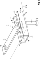
- the anchor rail 1 according to the invention shown has a C-profile rail 2, which has a rectangular hollow profile with a longitudinally continuous slot 3 in a first side 4, which can also be referred to as the top of the C-profile rail 2.
- the anchor rail 1 or its C-profile rail 2 is intended to be set in concrete in a structural part 5 such as a concrete floor so that, as in FIG Figure 1 To see, the first side 4 of the C-profile rail 2, having the slot 3, is flush with a surface of the structural part 5 and the C-profile rail 2 is sunk into the structural part 5. From the structural part 5 only individual edges are drawn and it is drawn transparently so that the anchor rail 1 is visible.
- anchoring elements 7 protrude, which are attached to the second side 6 of the C-profile rail 2, for example welded on.
- the anchoring elements 7 are bolts with flange-shaped feet 8 at their ends remote from the C-profile rail 2.
- the anchoring elements 7 are embedded in the concrete of the structural part 5 and hold the C-profile rail 2 against being torn out of the structural part 5 perpendicular to its surface. in the In the exemplary embodiment, the anchoring elements 7 are arranged in a longitudinal center plane of the C-profile rail 2.
- the anchoring elements 7 can, for example, also protrude obliquely from the second side 6 of the C-profile rail 2 in a V-shape when viewed in the longitudinal direction of the C-profile rail 2 and protrude into the structural part 5 (not shown).
- a surface anchor 9 which is strip-shaped in the exemplary embodiment and rests on the first side 4 of the C-profile rail 2 and on or from a third side 10 of the C-profile rail 2 adjoining the first side 4, is suspended in the slot 3 of the C-profile rail 2 Tab protrudes.
- the surface anchor 9 rests on the surface of the structural part 5.
- the surface anchor 9 has a single hook 11 which engages around a first slot edge 12 of the slot 3 of the C-profile rail 2 and in this way connects the surface anchor 9 to the C-profile rail 2 in a tensile manner.
- tensile strength is meant that the single hook 11 of the surface anchor 9 suspended in the slot 3 of the C-profile rail 2 transmits a transverse force acting transversely to the C-profile rail 2 as a tensile force acting in a longitudinal direction of the surface anchor 9 to the surface anchor 9.
- the surface anchor 9 Near an end remote from the C-profile rail 2 of the anchor rail 1 according to the invention and at least at a distance from the C-profile rail 2, the surface anchor 9 has a hole at one end of the bracket, which is generally referred to here as anchoring means 13 of the surface anchor 9.
- anchoring means 13 of the surface anchor 9 Through the hole in the bracket forming the anchoring means 13, the surface anchor 9 can be fixed at a distance from the C-profile rail 2 on the structural part 5 and thus serves to anchor the C-profile rail 2.
- a screw can be inserted through the anchoring means 13 designed as a hole of the surface anchor 9 are screwed into an expansion dowel, which is expanded and anchored in the structural part 5 (not shown).
- the surface anchor 9 can also be fixed, for example, by gluing onto the surface of the structural part 5.
- the adhesive forms the anchoring means that also connects the surface anchor 9 to the structural part 5 at a distance from the C-profile rail 2 when the adhesive is applied to the surface anchor 9 up to the C-profile rail 2.
- the C-profile rail 2 has a deformable strip 15 on the outside, which completely or almost completely covers the fourth side 14 of the C-profile rail 2 covered.
- the strip 15 consists of an elastic, solid foam.
- the fourth side 14 of the C-profile rail 2 adjoins its first side 4 with the slot 3 and the opposite second side 6 from which the anchoring elements 7 protrude.
- the fourth side 14 of the C-profile rail 2 is located opposite the third side 10, on or from which the surface anchor 9 protrudes.
- the deformable strip 15 enables a slight movement of the C-profile rail 2 in the structural part 5 transversely to the C-profile rail 2, parallel to the surface of the structural part 5 and away from the surface anchor 9 when the C-profile rail 2 is transverse to itself, that is is loaded along the surface anchor 9 and away from it. An early eruption of the concrete of the structural part 5 in the event of such a transverse load on the C-profile rail 2 is avoided.
- the C-profile rail 2 of the anchor rail 1 preferably has a plurality of surface anchors 9, which are suspended transversely to the C-profile rail 2, parallel to one another and at intervals in the longitudinal direction of the C-profile rail 2 from one another in the slot 3 of the C-profile rail 2 and on Structural part 5 are set.
- the surface anchors 9 secure the C-profile rail 2 against a transverse force and prevent the concrete from breaking out, especially if the C-profile rail 2 is arranged close to the edge in the structural part 5.
- the surface anchors 9 stand on an edge 16 of the structural part 5 that is close to the C-profile rail 2 opposite side from the C-profile rail 2.
- the surface anchor 9 can also be angled so that it penetrates laterally next to the C-profile rail 2 in the concrete of the structural part 5 and secures the C-profile rail 2 on the structural part 5 against a transverse force.
- the surface anchor 9 penetrates the surface of the structural part 5 laterally next to the C-profile rail 2, the surface of the structural part 5 being flush with the first side 4 of the C-profile rail 2 and thus one with the first side 4 of the C-profile rail 2 forms a flush level.
- the surface anchor 9 has a double hook 17 instead of the single hook 11 at its end.
- the double hook 17 engages around the first slot edge 12 of the slot 3 of the C-profile rail 2 and additionally engages under a second slot edge 18 opposite the first slot edge 12, so that the double hook 17 is not pulled out of the slot 3 and the surface anchor 9 is not can be lifted from the first side 4 of the C-profile rail 2.
- a hammer head screw 19 connects the surface anchor 9 to the C-profile rail 2.
- the hammer-head screw 19, which can generally also be understood as a fastener 20, is hung with its hammer head 21 in the C-profile rail 2, so that its shaft 22 on the first side 4 from the slot 3 of the C-profile rail 2 protrudes.
- the surface anchor 9 in this embodiment of the invention has a hole that the shaft 22 of the hammer head screw 19, which forms the fastener 20, reaches through, so that the surface anchor 9 is hooked into the slot 3 of the C-profile rail 2 and is connected to the C-profile rail 2 in this way.
- a component (not shown), for example a machine frame, can be fastened to the shaft 22 of the hammer head screw 19, which protrudes from the C profile rail 2 and at the same time from the structural part 5, of the hammer head screw 19 forming the fastener 20.
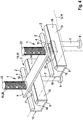
- the in Figure 4 illustrated embodiment of the invention are two C-profile rails 2 spaced apart and parallel to each other with their first sides 4 having the slot 3 flush with the surface of the structural part 5 sunk into this.
- Several surface anchors 9 arranged transversely to the C-profile rails 2 and parallel to one another connect the two C-profile rails 2, whereby a C-profile rail 2 arranged near an edge of the structural part 5 is secured to a C-profile rail 2 further away from the edge of the structural part 5 can be.
- Figure 4 only one surface anchor 9 is shown.
- the surface anchor 9 is formed by two tabs, each with an anchoring means 13 and a sheet metal strip 25, which has an opening 26.
- the sheet metal strip 25 is welded onto the first side 4 of the C-profile rail 2 in such a way that the opening 26 is oriented parallel to the slot 3 and thus does not cover the slot 3 of the C-profile rail 2.
- the main difference of the embodiment of the Figure 5 Compared to the previous exemplary embodiments, it is not the first side 4 of the C-profile rail 2 that is flush with the surface of the structural part 5, but that the surface anchor 9 is flush with the surface of the component 5. As a result, the entire surface of the component 5 can be used, since the surface anchor 9 does not protrude.
- the C-profile rail 2 is cast into the structural part 5 together with the surface anchor 9.
- the surface anchor 9 has a surface structure 23 in the form of a toothing 24.
- a toothing 24 This allows, for example, a hammer head screw that by means of a toothed washer is fastened in the slot 3, can be secured against slipping in the longitudinal direction of the rail, that is, along the slot 3 (not shown).
- the toothed washer engages in the toothing 24.
- the surface anchor 9 can consist of any material, for example a metal strip. It is also possible that the surface anchor 9 consists of plastic, in particular of fiber-reinforced plastic. For example, the surface anchor 9 can consist of a prepreg or have such a prepreg. A prepreg has fibers embedded in a synthetic resin, it being possible for the synthetic resin to be cured for bonding to the surface of the structural part 5 (not shown).
- the surface anchor 9 consists of a pseudoplastically expanded shape memory alloy or at least has one.
- the surface anchor 9 is shortened when it is heated to or above a transformation temperature of the shape memory alloy. This makes it possible to generate a tensile stress in the surface anchor 9, which prestresses the C-profile rail 2 transversely to the C-profile rail 2 and parallel to the surface of the structural part 5 away from the edge of the structural part 5 near the C-profile rail 2.
Landscapes
- Engineering & Computer Science (AREA)
- Architecture (AREA)
- Physics & Mathematics (AREA)
- Electromagnetism (AREA)
- Civil Engineering (AREA)
- Structural Engineering (AREA)
- Joining Of Building Structures In Genera (AREA)
Abstract
Description
- Die Erfindung betrifft eine Ankerschiene mit den Merkmalen des Oberbegriffs des Anspruchs 1. Des Weiteren betrifft die Erfindung zwei Befestigungsanordnungen mit einer solchen Ankerschiene gemäß den Ansprüchen 11 und 12.
- Ankerschienen werden typischerweise bündig versenkt in einem Boden oder auch einer Wand aus Beton angeordnet und dienen einer Befestigung von Gegenständen, beispielsweise von Maschinen, mit Hilfe beispielsweise von Hammerkopfschrauben. "Bündig versenkt" bedeutet, dass die Ankerschiene in den Beton eingebettet und eine Seite der Ankerschiene bündig mit einer Oberfläche beispielsweise des Betons ist. Bei der Herstellung des Bodens oder dergleichen werden die Ankerschienen auf drei Seiten mit dem Beton umgossen. Die Ankerschienen weisen typischerweise eine C-Profilschiene auf, das heißt ein quadratisches Rohrprofil oder ein Rechteck-Rohrprofil mit einem durchgehenden Längsschlitz in einer Quermitte einer hier auch als "Oberseite" bezeichneten Seite.
- Die europäische Patentanmeldung
EP 3 438 361 A1 offenbart eine Ankerschiene mit einer C-Profilschiene, von der zu einer Verankerung in Beton bolzenförmige Anker mit Fußscheiben in einer Längsmittelebene der C-Profilschiene von einer einem Schlitz der C-Profilschiene gegenüberliegenden Unterseite abstehen, die bei einem Einbetonieren der Ankerschiene in den Beton einbetoniert werden und die Ankerschiene gegen ein Herausreißen aus dem Beton senkrecht zu einer Oberfläche des Betons im Beton verankern. Die Ankerschiene ist parallel zu und nahe der Kante des Betonkörpers angeordnet. Wirkt auf die Ankerschiene parallel zur Oberfläche des Betons und in Richtung der Kante eine zu große Querkraft, könnte die Ankerschiene aufgrund der Anordnung nahe der Kante aus dem Betonkörper herausbrechen und im Betonkörper einen Ausbruchkegel oder generell eine Ausbruchstelle hinterlassen. Daher müssen Ankerschienen, die baulich bedingt nahe an einer Kante eines Betonkörpers angeordnet sind, zumeist "rückverankert" werden. Zu einer Rückverankerung gegen eine Querkraft quer zur C-Profilschiene und parallel zur Oberfläche des Betons weist die bekannte Ankerschiene stangenförmige Anker auf, die senkrecht zu der Mittelebene, in der sich die bolzenförmigen Anker befinden, von der dem Schlitz der C-Profilschiene gegenüberliegenden Unterseite abstehen. Beim Einbetonieren werden die stangenförmigen Anker parallel zu der Oberfläche des Betons und um eine Höhe der C-Profilschiene versenkt unter der Oberfläche des Betons einbetoniert. Die stangenförmigen Anker nehmen eine auf die Ankerschiene einwirkende Querkraft auf und verhindern, dass die Ankerschiene in Richtung der Kante des Betonkörpers aus dem Betonkörper herausbrechen kann. Nachteilig an der Rückverankerung des Stands der Technik ist, dass diese Rückverankerung nicht nachträglich an einen Betonkörper angebracht, sondern zwangsläufig bei der Herstellung des Betonkörpers bereits mit eingegossen werden muss. - Aufgabe der Erfindung ist, eine flexiblere Rückverankerung vorzuschlagen, welche zum einen eine Möglichkeit zu einer nachträglichen Rückverankerung einer Ankerschiene an oder in Beton bietet und zum anderen eine geplante Rückverankerung einer Ankerschiene bereits während des Gießens des Betons ermöglicht.
- Diese Aufgabe wird erfindungsgemäß durch die Merkmale der Ansprüche 1, 11 und 12 gelöst. Die erfindungsgemäße Ankerschiene weist eine C-Profilschiene mit einem Schlitz in einer ersten Seite der C-Profilschiene auf, die zu einem Einbetonieren vorgesehen ist, derart, dass die erste Seite der C-Profilschiene insbesondere bündig mit einer Oberfläche des Betons und die C-Profilschiene im Übrigen in den Beton eingebettet ist. Der Schlitz ist insbesondere ein in einer Längsrichtung der C-Profilschiene durchgehender Schlitz insbesondere in einer Quermitte der C-Profilschiene beziehungsweise ihrer ersten Seite. Von einer der ersten Seite gegenüberliegenden zweiten Seite stehen ein oder mehrere Verankerungselemente ab, die die einbetonierte C-Profilschiene in dem Beton verankern.
- Des Weiteren weist die erfindungsgemäße Ankerschiene mindestens einen Oberflächenanker für eine Rückverankerung der C-Profilschiene auf, der an der ersten Seite der C-Profilschiene aufliegt und von einer, das heißt, bezogen auf eine an die erste Seite angrenzenden dritten Seite der C-Profilschiene absteht. Der Teil des Oberflächenankers, der von der C-Profilschiene absteht, steht insbesondere in einem rechten Winkel von der C-Profilschiene ab und ist als eine Lasche ausgestaltet. Die Lasche ist insbesondere ein Flachstahl oder ein zugeschnittenes oder gestanztes Stahlblech. Die Lasche weist eine Breite insbesondere von weniger als 60 mm, bevorzugt zwischen 30 mm und 50 mm auf. Unter "Breite" ist die Ausdehnung der Lasche in Längsrichtung der C-Profilschiene zu verstehen. Insbesondere ist eine Länge der Lasche um ein Vielfaches größer als die Breite der Lasche. Unter der "Länge" ist die Erstreckung der Lasche weg von der Ankerschiene zu verstehen. Bevorzugt entspricht die Länge der Lasche mindestens dem dreifachen und insbesondere mindestens dem fünffachen der Breite der Lasche. Abhängig von der baulichen Umgebung und dem Einsatzzweck des Oberflächenankers kann die Länge jedoch auch dem fünf- bis zehn oder zwanzig-fachen der Breite entsprechen. Auch noch längere Laschen sind möglich. Insbesondere sind bei längeren Ankerschienen mehrere Oberflächenanker, insbesondere äquidistant zueinander, an der Ankerschiene angeordnet, wodurch eine konstante Rückverankerung über die komplette Ankerschienenlänge erreicht wird.
- Der Oberflächenanker muss nicht direkt mit der dritten Seite verbunden oder direkt an dieser angeordnet sein, sondern nur über diese Fläche ab- beziehungsweise überstehen. Die Auflage kann direkt oder indirekt, beispielsweise über ein Zwischenstück zum Höhenausgleich erfolgen. Vorzugsweise kann der Oberflächenanker an der ersten Seite mit der C-Profilschiene verbunden sein. Insbesondere steht der Oberflächenanker mit dem Schlitz der C-Profilschiene in Wirkverbindung und kann hierbei zusätzlich mit der ersten Seite der C-Profilschiene verbunden sein. Der Oberflächenanker muss jedoch nicht zwangsläufig mit dem Schlitz in Eingriff stehen. Der Oberflächenanker könnte beispielsweise lediglich oberflächenbündig und insbesondere den Schlitz nur teilweise abdeckend auf die erste Seite der C-Profilschiene aufgelegt und dort, insbesondere durch Schweißen, mit der C-Profilschiene befestigt sein. Der Oberflächenanker kann zumindest abschnittsweise als eine Art Blechstreifen mit einem Durchbruch ausgestaltet sein, wobei die Dimension des Durchbruchs im Wesentlichen mit der Ausdehnung des Schlitzes der C-Profilschiene korrespondiert. Insbesondere ist der Blechstreifen mit dem Durchbruch derart auf die erste Seite der C-Profilschiene aufgeschweißt oder anderweitig, beispielsweise durch nieten, mit dieser befestigt, dass der Durchbruch den Schlitz höchstens teilweise bedeckt. Insbesondere korrespondiert eine Breite des Durchbruchs mit der Querbreite des Schlitzes der C-Profilschiene
- Der Oberflächenanker, genauer formuliert die Lasche des Oberflächenankers, ist so an der C-Profilschiene angeordnet, dass er bei in vorgesehener Weise einbetonierter C-Profilschiene zur Seite von der C-Profilschiene absteht und auf der Oberfläche des Betons aufliegt oder bündig mit der Oberfläche des Betons abschließt. Der oder die Oberflächenanker weisen ein Verankerungsmittel in einem Abstand von der C-Profilschiene insbesondere an einem Ende der Lasche auf. Das Verankerungsmittel ist allgemein eine Möglichkeit oder Einrichtung zu einer Befestigung des Oberflächenankers am Beton. Es kann sich beispielsweise um ein Loch in der Lasche handeln, durch das der Oberflächenanker mittels eines Befestigungsmittels, beispielsweise einem Bolzenanker, einer Betonschraube, einer im Beton chemisch befestigten Ankerstange oder dergleichen an dem Beton festlegbar ist. Möglich ist eine Festlegung des Oberflächenankers beispielsweise auch durch Aufkleben auf den Beton, wobei hier ein Flächenmittelpunkt einer Klebefläche den Abstand von der C-Profilschiene aufweist, wenn der Klebstoff bis zur C-Profilschiene heran reicht. Das Verankerungselement ist in diesem Fall der Klebstoff. Der Oberflächenanker kann jedoch auch derart tief einem Bauwerksteil aus Beton verankert, insbesondere in das Bauwerksteil eingegossen sein, dass dieser mit der Oberfläche des Betons, respektive des Bauwerkteils insbesondere bündig ist. Der Oberflächenanker schließt also insbesondere bündig mit der Oberfläche ab. Bei dieser geplanten Art der Verankerung der C-Profilschiene in Beton wird somit der Oberflächenanker zumindest teilweise stoffschlüssig mit dem Beton verbunden und die Verankerungsmittel werden hierbei insbesondere ebenfalls zumindest teilweise in den Beton mit eingegossen. In diesem Fall sind die Verankerungsmittel insbesondere Löcher, Bolzen, Wellenanker oder dergleichen. Der Vorteil der geplanten Art der Verankerung liegt darin begründet, dass die Oberfläche des Betons im Wesentlichen komplett nutzbar ist und nicht durch den Oberflächenanker blockiert ist. Bei der nachträglichen Verankerung liegt der Oberflächenanker auf der C-Profilschiene auf und folglich ergibt sich dadurch eine möglicherweise störende Erhebung auf der sonst ebenen Oberfläche des Betons.
- Die Erfindung hat zum einen den Vorteil, dass eine bereits einbetonierte C-Profilschiene einer Ankerschiene nachträglich gegen eine Querkraftbelastung gesichert, sprich rückverankert werden kann. Das kann bei einer randnahen Anordnung der C-Profilschiene in Beton vorteilhaft oder sogar notwendig sein, wenn ein Ausbruch des Betons seitlich der C-Profilschiene am Rand des Betons zu befürchten oder bereits aufgetreten ist. Eine Verhinderung des Betonausbruchs liefert auch das geplante Verankern der C-Profilschiene, wobei hierbei, wie bereits erwähnt, die komplette Oberfläche des Betons genutzt werden kann.
- Erfindungsgemäß kann der Oberflächenanker, genauer formuliert die Lasche, an einer mit der ersten, den Schlitz aufweisenden Seite der C-Profilschiene bündigen Ebene seitlich von der C-Profilschiene an beziehungsweise von deren dritter Seite abstehen oder die mit der ersten Seite der C-Profilschiene bündigen Ebene durchsetzen. Die dritte Seite ist die an die erste, den Schlitz aufweisenden Seite angrenzende Seite der C-Profilschiene. Im ersten Fall liegt der Oberflächenanker auf der Oberfläche des Betons auf, wenn die C-Profilschiene wie vorgesehen einbetoniert ist. Im zweiten Fall dringt der Oberflächenanker seitlich von der C-Profilschiene in den Beton ein. Der zweite Fall ist für ein ursprüngliches Anbringen des Oberflächenankers an der C-Profilschiene vorgesehen, so dass der Oberflächenanker beim Einbetonieren der C-Profilschiene ebenfalls einbetoniert wird und nicht nachträglich in den Beton versenkt werden muss. Diese Ausführung hat, wie bereits erwähnt, den Vorteil, dass der Oberflächenanker nicht auf seiner vollen Länge auf dem Beton aufliegt, sondern sich teilweise oder gänzlich im Beton befindet.
- Eine Befestigung des Oberflächenankers an der C-Profilschiene ist beispielsweise durch Einhängen des Oberflächenankers in den Schlitz der C-Profilschiene möglich. Die Einhängung muss nur in der Richtung, in der der Oberflächenanker von der C-Profilschiene absteht, zugfest sein, das heißt eine Querkraft der C-Profilschiene als Zugkraft auf den Oberflächenanker übertragen können. Das Einhängen des Oberflächenankers in den Schlitz der C-Profilschiene ist eine einfache, schnelle und preisgünstige Möglichkeit des Verbindens des Oberflächenankers mit der C-Profilschiene.
- Der Oberflächenanker kann einen Einfachhaken aufweisen, der zum Verbinden mit der C-Profilschiene einen ersten Schlitzrand des Schlitzes der C-Profilschiene umgreift, so dass er eine Querkraft der C-Profilschiene als Zugkraft auf den Oberflächenanker überträgt. Der Oberflächenanker kann auch einen Doppelhaken aufweisen, der den ersten Schlitzrand des Schlitzes der C-Profilschiene umgreift und einen gegenüberliegenden zweiten Schlitzrand des Schlitzes der C-Profilschiene untergreift, wenn der Doppelhaken beziehungsweise der Oberflächenanker mit der C-Profilschiene verbunden ist, so dass der Doppelhaken nicht ohne Weiteres aus der C-Profilschiene herausgehoben werden kann.
- Zum Verbinden des Oberflächenankers mit der C-Profilschiene sieht eine andere Ausgestaltung der Erfindung einen an beziehungsweise in der C-Profilschiene befestigten Befestiger vor, der einen Schaft aufweist, der aus dem Schlitz in der ersten Seite der C-Profilschiene vorsteht. Bei dem Befestiger kann es sich beispielsweise um eine Hammerkopfschraube oder einen Nutenstein mit eingeschraubtem Gewindebolzen handeln. An dem aus dem Schlitz der C-Profilschiene vorstehenden Schaft des Befestigers ist der Oberflächenanker befestigt.
- In einer weiteren vorteilhaften Ausgestaltung der Erfindung weist der Oberflächenanker auf einer der ersten Seite abgewandten Seite eine Oberflächenstrukturierung, insbesondere eine Verzahnung, auf. Hierdurch kann ein Befestiger, beispielsweise ein Befestiger wie im vorangegangenen Absatz beschrieben, gegen Verschiebung längs des Schlitzes der C-Profilschiene durch Form und/oder Reibschluss gesichert werden.
- Eine Ausgestaltung der Erfindung sieht vor, dass der Oberflächenanker die C-Profilschiene mit einer zweiten C-Profilschiene verbindet, die in einem Abstand von der einen C-Profilschiene angeordnet ist. Der Oberflächenanker trägt die Last von der einen C-Profilschiene auf die andere, in einem Abstand angeordnete C-Profilschiene ab.
- Eine Ausgestaltung der Erfindung sieht vor, dass der Oberflächenanker eine pseudoplastisch gedehnte Formgedächtnislegierung aufweist oder aus einer pseudoplastisch gedehnten Formgedächtnislegierung besteht. Formgedächtnislegierungen sind Metalllegierungen, die durch eine Phasenumwandlung ihrer Kristallstrukturen, insbesondere zwischen Martensit und Austenit, ihre Form ändern. Die Phasenumwandlung und Formänderung erfolgt bei Erreichen oder Überschreiten einer Umwandlungstemperatur. Zuvor muss die Formgedächtnislegierung pseudoplastisch verformt werden, was typischerweise, aber nicht zwingend, durch eine mechanische Verformung erfolgt, die anschließend durch Erwärmung auf oder über die Umwandlungstemperatur vollständig oder teilweise rückgängig gemacht werden kann. Es sind auch Formgedächtnislegierungen mit einem Zweiweg-Effekt bekannt, die sich bei hoher Temperatur umformen und bei niedriger Temperatur vollständig oder teilweise rückumformen. Bei dieser Ausgestaltung der Erfindung lässt sich eine Zugspannung im Oberflächenanker erzeugen, nachdem der Oberflächenanker an oder in dem Beton festgelegt worden ist, indem der Oberflächenanker auf oder über die Umwandlungstemperatur der Formgedächtnislegierung erwärmt wird, das heißt, der Oberflächenanker wird vorgespannt.
- Eine Ausgestaltung der Erfindung sieht einen elastisch und/oder plastisch verformbaren Streifen außen an einer an die erste Seite angrenzenden und der dritten Seite gegenüberliegenden vierten Seite der C-Profilschiene vor. Die erste Seite weist den Schlitz auf und von der angrenzenden dritten Seite steht der Oberflächenanker ab. Der verformbare Streifen befindet sich also außen an der C-Profilschiene gegenüber der Seite, von der der Oberflächenanker absteht. Vorzugsweise nimmt der verformbare Streifen eine gesamte Fläche der vierten Seite der C-Profilschiene ein. Der verformbare Streifen ermöglicht eine geringe Verlagerung der C-Profilschiene im Beton in einer Richtung quer zur C-Profilschiene entgegengesetzt zu der Richtung, in der der Oberflächenanker von der C-Profilschiene absteht. Die geringe Verlagerung durch eine Kompression des Streifens ermöglicht es insbesondere den Einfach- und den Doppelhaken, sich in dem Schlitz der C-Profilschiene spannend festzulegen, bevor die C-Profilschiene in Kontakt zum Beton tritt. Anders gesprochen ist es möglich, dass ein gewisses Spiel zwischen den Einfach- und den Doppelhaken und der C-Profilschiene kompensiert werden kann, bevor die C-Profilschiene in den eigentlichen Kontakt zum Beton tritt.
- Zur Erläuterung der erfindungsgemäßen Befestigungsanordnung werden die vorstehenden Erläuterungen der erfindungsgemäßen Ankerschiene in Bezug genommen.
- In einer erfindungsgemäßen Befestigungsanordnung zur Rückverankerung der Ankerschiene ist die C-Profilschiene der Ankerschiene so versenkt in einem Bauwerksteil aus Beton verankert, dass ihre den Schlitz aufweisende erste Seite bündig mit einer Oberfläche des Bauwerkteils ist. Zudem ist der Oberflächenanker an der ersten Seite mit der C-Profilschiene verbunden und steht an der an die erste Seite angrenzenden dritten Seite von der C-Profilschiene ab. Der Oberflächenanker, genauer formuliert die Lasche, liegt hierbei auf der Oberfläche des Bauwerkteils auf und ist mit Abstand zur C-Profilschiene an dem Bauwerkteil festgelegt oder dringt seitlich von der C-Profilschiene in das Bauwerkteil ein.
- Insbesondere ist in dieser Befestigungsanordnung die C-Profilschiene nahe an einer Kante des Bauwerkteils, also randnah, und insbesondere parallel zur Kante des Bauwerkteils angeordnet. "Nahe" meint hier, dass der Abstand der C-Profilschiene von der Kante maximal dem Doppelten der Länge der C-Profilschiene entspricht, insbesondere dass der Abstand geringer als die Länge der Profilschiene ist. Der Oberflächenanker, genauer formuliert die Lasche des Oberflächenankers, erstreckt sich in einem insbesondere rechten Winkel zur C-Schiene von der Kante des Bauwerkteils weg. Die Lasche des Oberflächenankers ist also der Kante abgewandt. Die Lasche ist insbesondere an einem Laschenende, welches der C-Profilschiene abgewandt ist, auf der Oberfläche des Bauwerkteils oder im Bauwerkteil selbst festgelegt, wodurch eine stabile Rückverankerung der Ankerschiene gewährleistet ist. Durch die erfindungsgemäße Befestigungsanordnung können Ankerschienen somit sicher in Randnähe in einem Bauteil eingegossen werden ohne dass die Gefahr besteht, dass sie bei Belastung aus dem Bauwerkteil herausbrechen.
- Die C-Profilschiene kann wie bereits beschrieben, auch derart tief versenkt in dem Bauwerksteil aus Beton verankert, insbesondere in das Bauwerksteil eingegossen sein, dass der Oberflächenanker bündig mit der Oberfläche des Bauwerkteils ist.
- Die vorstehend in der Beschreibung genannten Merkmale und Merkmalskombinationen, Ausführungen und Ausgestaltungen der Erfindung, sowie die nachfolgend in der Figurenbeschreibung genannten und/oder in einer Figur gezeichneten Merkmale und Merkmalskombinationen sind nicht nur in der jeweils angegebenen oder gezeichneten Kombination, sondern auch in grundsätzlich beliebigen anderen Kombinationen oder aber einzeln verwendbar. Es sind Ausführungen der Erfindung möglich, die nicht alle Merkmale eines abhängigen Anspruchs aufweisen. Auch können einzelne Merkmale eines Anspruchs durch andere offenbarte Merkmale oder Merkmalskombinationen ersetzt werden. Ausführungen der Erfindung, die nicht alle Merkmale des oder der Ausführungsbeispiele, sondern einen grundsätzlich beliebigen Teil der gekennzeichneten Merkmale eines Ausführungsbeispiels gegebenenfalls in Kombination mit einem, mehreren oder allen Merkmalen eines oder mehrerer weiterer Ausführungsbeispiele aufweisen, sind möglich.
- Die Erfindung wird nachfolgend anhand in der Zeichnung dargestellter Ausführungsbeispiele näher erläutert. Die fünf Figuren zeigen fünf Ausführungsbeispiele erfindungsgemäßer Ankerschienen in perspektivischer Darstellung. Aus Gründen der Übersichtlichkeit und der Einfachheit werden in allen Figuren identische Bezugszeichen verwendet.
- Die in
Figur 1 dargestellte, erfindungsgemäße Ankerschiene 1 weist eine C-Profilschiene 2 auf, die ein Rechteck-Hohlprofil mit einem in Längsrichtung durchgehenden Schlitz 3 in einer ersten Seite 4 aufweist, die auch als Oberseite der C-Profilschiene 2 bezeichnet werden kann. - Die Ankerschiene 1 beziehungsweise ihre C-Profilschiene 2 ist zu einem Einbetonieren in einem Bauwerksteil 5 wie beispielsweise einen Betonboden so vorgesehen, dass, wie in
Figur 1 zu sehen, die erste, den Schlitz 3 aufweisende Seite 4 der C-Profilschiene 2 bündig mit einer Oberfläche des Bauwerksteils 5 und die C-Profilschiene 2 im Übrigen in das Bauwerksteil 5 versenkt ist. Vom Bauwerksteil 5 sind nur einzelne Kanten gezeichnet und es ist durchsichtig gezeichnet, damit die Ankerschiene 1 sichtbar ist. - Von einer der ersten Seite 4 gegenüberliegenden zweiten Seite 6, die auch als Unterseite der C-Profilschiene 2 bezeichnet werden kann, stehen Verankerungselemente 7 ab, die an der zweiten Seite 6 der C-Profilschiene 2 befestigt, beispielsweise angeschweißt sind. Im Ausführungsbeispiel sind die Verankerungselemente 7 Bolzen mit flanschförmigen Füßen 8 an ihren der C-Profilschiene 2 fernen Enden. Die Verankerungselemente 7 sind in den Beton des Bauwerksteils 5 eingebettet und halten die C-Profilschiene 2 gegen ein Herausreißen aus dem Bauwerksteil 5 senkrecht zu dessen Oberfläche. Im Ausführungsbeispiel sind die Verankerungselemente 7 in einer Längsmittelebene der C-Profilschiene 2 angeordnet. Die Verankerungselemente 7 können beispielsweise auch in der Längsrichtung der C-Profilschiene 2 gesehen V-förmig schräg auseinander von der zweiten Seite 6 der C-Profilschiene 2 abstehen und in das Bauwerksteil 5 ragen (nicht dargestellt).
- In den Schlitz 3 der C-Profilschiene 2 ist ein im Ausführungsbeispiel streifenförmiger Oberflächenanker 9 eingehängt, der auf der ersten Seite 4 der C-Profilschiene 2 aufliegt und an beziehungsweise von einer an die erste Seite 4 angrenzenden dritten Seite 10 der C-Profilschiene 2 als Lasche absteht. Der Oberflächenanker 9 liegt auf der Oberfläche des Bauwerksteils 5 auf. An einem Ende weist der Oberflächenanker 9 einen Einfachhaken 11 auf, der einen ersten Schlitzrand 12 des Schlitzes 3 der C-Profilschiene 2 umgreift und auf diese Weise den Oberflächenanker 9 zugfest mit der C-Profilschiene 2 verbindet. Mit "zugfest" ist gemeint, dass der in den Schlitz 3 der C-Profilschiene 2 eingehängte Einfachhaken 11 des Oberflächenankers 9 eine quer zur C-Profilschiene 2 wirkende Querkraft als in einer Längsrichtung des Oberflächenankers 9 wirkende Zugkraft auf den Oberflächenanker 9 überträgt.
- Nahe einem der C-Profilschiene 2 der erfindungsgemäßen Ankerschiene 1 fernen Ende und jedenfalls in einem Abstand von der C-Profilschiene 2 weist der Oberflächenanker 9 an einem Ende der Lasche ein Loch auf, das hier verallgemeinernd als Verankerungsmittel 13 des Oberflächenankers 9 bezeichnet wird. Durch das das Verankerungsmittel 13 bildende Loch in der Lasche ist der Oberflächenanker 9 mit Abstand von der C-Profilschiene 2 an dem Bauwerksteil 5 festlegbar und dient so der Rückverankerung der C-Profilschiene 2. Dazu kann beispielsweise eine Schraube durch das als Loch ausgebildete Verankerungsmittel 13 des Oberflächenankers 9 in einen Spreizdübel geschraubt werden, der in dem Bauwerksteil 5 aufgespreizt und verankert ist (nicht dargestellt).
- Die Festlegung des Oberflächenankers 9 kann beispielsweise auch durch Kleben auf die Oberfläche des Bauwerksteils 5 erfolgen. In diesem Fall bildet der Klebstoff das Verankerungsmittel, das den Oberflächenanker 9 auch dann mit Abstand von der C-Profilschiene 2 mit dem Bauwerksteil 5 verbindet, wenn der Klebstoff bis zur C-Profilschiene 2 auf den Oberflächenanker 9 aufgetragen ist.
- An einer vierten Seite 14 weist die C-Profilschiene 2 außen einen verformbaren Streifen 15 auf, der die vierte Seite 14 der C-Profilschiene 2 vollständig oder nahezu vollständig bedeckt. Im Ausführungsbeispiel besteht der Streifen 15 aus einem elastischen, festen Schaum. Die vierte Seite 14 der C-Profilschiene 2 grenzt an deren erste Seite 4 mit dem Schlitz 3 und an die gegenüberliegende zweite Seite 6, von der die Verankerungselemente 7 abstehen, an. Die vierte Seite 14 der C-Profilschiene 2 befindet sich der dritten Seite 10 gegenüber, an beziehungsweise von der der Oberflächenanker 9 absteht. Der verformbare Streifen 15 ermöglicht eine geringe Bewegung der C-Profilschiene 2 in dem Bauwerksteil 5 quer zur C-Profilschiene 2, parallel zu der Oberfläche des Bauwerksteils 5 und weg von dem Oberflächenanker 9, wenn die C-Profilschiene 2 quer zu sich, das heißt längs zu dem Oberflächenanker 9 und von diesem weg belastet wird. Ein frühzeitiger Ausbruch des Betons des Bauwerksteils 5 bei einer solchen Querbeanspruchung der C-Profilschiene 2 wird dadurch vermieden.
- Die C-Profilschiene 2 der erfindungsgemäßen Ankerschiene 1 weist vorzugsweise mehrere Oberflächenanker 9 auf, die quer zur C-Profilschiene 2, parallel zueinander und mit Abständen in der Längsrichtung der C-Profilschiene 2 voneinander in den Schlitz 3 der C-Profilschiene 2 eingehängt und am Bauwerksteil 5 festgelegt sind. Die Oberflächenanker 9 sichern die C-Profilschiene 2 gegen eine Querkraft und vermeiden einen Ausbruch des Betons insbesondere bei einer randnahen Anordnung der C-Profilschiene 2 im Bauwerksteil 5. Die Oberflächenanker 9 stehen auf einer dem der C-Profilschiene 2 nahen Rand 16 des Bauwerksteils 5 gegenüberliegenden Seite von der C-Profilschiene 2 ab.
- Wie in
Figur 1 mit Strichlinien dargestellt, kann der Oberflächenanker 9 auch abgewinkelt sein, so dass er seitlich neben der C-Profilschiene 2 in den Beton des Bauwerksteils 5 eindringt und die C-Profilschiene 2 am Bauwerksteil 5 gegen eine Querkraft sichert. In diesem Fall durchdringt der Oberflächenanker 9 die Oberfläche des Bauwerksteils 5 seitlich neben der C-Profilschiene 2, wobei die Oberfläche des Bauwerksteils 5 bündig mit der ersten Seite 4 der C-Profilschiene 2 ist und somit eine mit der ersten Seite 4 der C-Profilschiene 2 bündige Ebene bildet. - In
Figur 2 weist der Oberflächenanker 9 einen Doppelhaken 17 anstelle des Einfachhakens 11 an seinem Ende auf. Wie der Einfachhaken 11 umgreift der Doppelhaken 17 den ersten Schlitzrand 12 des Schlitzes 3 der C-Profilschiene 2 und greift zusätzlich unter einen dem ersten Schlitzrand 12 gegenüberliegenden zweiten Schlitzrand 18, so dass der Doppelhaken 17 nicht aus dem Schlitz 3 herausgezogen und der Oberflächenanker 9 nicht von der ersten Seite 4 der C-Profilschiene 2 abgehoben werden kann. - Bei dem in
Figur 3 dargestellten Ausführungsbeispiel der Erfindung verbindet eine Hammerkopfschraube 19 den Oberflächenanker 9 mit der C-Profilschiene 2. Die Hammerkopfschraube 19, die allgemein auch als Befestiger 20 aufgefasst werden kann, ist mit ihrem Hammerkopf 21 in die C-Profilschiene 2 eingehängt, so dass ihr Schaft 22 auf der ersten Seite 4 aus dem Schlitz 3 der C-Profilschiene 2 vorsteht. Anstelle des Hakens 11, 17 weist der Oberflächenanker 9 bei diesem Ausführungsbeispiel der Erfindung ein Loch auf, das der Schaft 22 der Hammerkopfschraube 19, die den Befestiger 20 bildet, durchgreift, so dass der Oberflächenanker 9 am Schlitz 3 der C-Profilschiene 2 eingehängt und auf diese Weise mit der C-Profilschiene 2 verbunden ist. An dem aus der C-Profilschiene 2 und zugleich aus dem Bauwerksteil 5 vorstehenden Schaft 22 der den Befestiger 20 bildenden Hammerkopfschraube 19 kann ein nicht dargestelltes Bauteil, beispielsweise ein Maschinengestell befestigt werden. - Bei dem in
Figur 4 dargestellten Ausführungsbeispiel der Erfindung sind zwei C-Profilschienen 2 mit Abstand voneinander und parallel zueinander mit ihren den Schlitz 3 aufweisenden ersten Seiten 4 bündig mit der Oberfläche des Bauwerksteils 5 in dieses versenkt angeordnet. Mehrere quer zu den C-Profilschienen 2 und parallel zueinander angeordnete Oberflächenanker 9 verbinden die beiden C-Profilschienen 2, wodurch eine nahe einem Rand des Bauwerksteils 5 angeordnete C-Profilschiene 2 an einer weiter von dem Rand des Bauwerksteils 5 entfernten C-Profilschiene 2 gesichert werden kann. InFigur 4 ist nur ein Oberflächenanker 9 dargestellt. - Bei dem in
Figur 5 dargestellten Ausführungsbeispiel ist der Oberflächenanker 9 durch zwei Laschen mit jeweils einem Verankerungsmittel 13 sowie einem Blechstreifen 25, der einen Durchbruch 26 aufweist, gebildet. Der Blechstreifen 25 ist so auf der ersten Seite 4 der C-Profilschiene 2 angeschweißt, dass der Durchbruch 26 parallel zum Schlitz 3 orientiert ist und somit den Schlitz 3 der C-Profilschiene 2 nicht verdeckt. Der wesentliche Unterschied des Ausführungsbeispiels derFigur 5 verglichen mit den vorangegangenen Ausführungsbeispielen ist, dass nicht die erste Seite 4 der C-Profilschiene 2 bündig mit der Oberfläche des Bauwerksteils 5 ist, sondern dass der Oberflächenanker 9 bündig mit der Oberfläche des Bauteils 5 abschließt. Dadurch kann die komplette Oberfläche des Bauteils 5 genutzt werden, da kein Überstand durch den Oberflächenanker 9 entsteht. Die C-Profilschiene 2 ist zusammen mit dem Oberflächenanker 9 in das Bauwerksteil 5 eingegossen. - Der Oberflächenanker 9 weist eine Oberflächenstrukturierung 23 in Form einer Verzahnung 24 auf. Dadurch kann beispielsweise eine Hammerkopfschraube, die mittels einer verzahnten Unterlegscheibe in dem Schlitz 3 befestigt ist, gegen ein Verrutschen in Schienenlängsrichtung, also entlang des Schlitzes 3, gesichert werden (nicht dargestellt). Hierbei greift die verzahnte Unterlegscheibe in die Verzahnung 24 ein.
- Der Oberflächenanker 9 kann aus einem grundsätzlich beliebigen Material, beispielsweise aus einem Metallstreifen bestehen. Möglich ist auch, dass der Oberflächenanker 9 aus Kunststoff, insbesondere aus faserverstärkten Kunststoff besteht. Beispielsweise kann der Oberflächenanker 9 aus einem Prepreg bestehen oder ein solches aufweisen. Ein Prepreg weist in ein Kunstharz eingebettete Fasern auf, wobei das Kunstharz zum Aufkleben auf die Oberfläche des Bauwerksteils 5 ausgehärtet werden kann (nicht dargestellt).
- Ein Ausführungsbeispiel der Erfindung sieht vor, dass der Oberflächenanker 9 aus einer pseudoplastisch gedehnten Formgedächtnislegierung besteht oder jedenfalls eine solche aufweist. Der Oberflächenanker 9 verkürzt sich, wenn er auf oder über eine Umwandlungstemperatur der Formgedächtnislegierung erwärmt wird. Das ermöglicht es, eine Zugspannung in dem Oberflächenanker 9 zu erzeugen, die die C-Profilschiene 2 quer zur C-Profilschiene 2 und parallel zur Oberfläche des Bauwerksteils 5 weg von dem der C-Profilschiene 2 nahen Rand des Bauwerksteils 5 vorspannt.
- Die Ankerschiene 1 mit ihrer in das Bauwerksteil 5 eingebetteten C-Profilschiene 2, den von ihrer Unterseite abstehenden und ebenfalls in das Bauwerksteil 5 eingebetteten Verankerungselementen 7 und dem oder den Oberflächenankern 9, die am oder im Bauwerksteil 5 festgelegt sind, bilden eine erfindungsgemäße Befestigungsanordnung.
-
- 1
- Ankerschiene
- 2
- C-Profilschiene
- 3
- Schlitz
- 4
- erste Seite
- 5
- Bauwerksteil
- 6
- zweite Seite
- 7
- Verankerungselement
- 8
- Fuß
- 9
- Oberflächenanker
- 10
- dritte Seite
- 11
- Einfachhaken
- 12
- erster Schlitzrand
- 13
- Verankerungsmittel
- 14
- vierte Seite
- 15
- Streifen
- 16
- Rand
- 17
- Doppelhaken
- 18
- zweiter Schlitzrand
- 19
- Hammerkopfschraube
- 20
- Befestiger
- 21
- Hammerkopf
- 22
- Schaft
- 23
- Oberflächenstrukturierung
- 24
- Verzahnung
- 25
- Blechstreifen
- 26
- Durchbruch
Claims (12)
- Ankerschiene zur Verankerung in Beton, mit einer C-Profilschiene (2), die einen Schlitz (3) in einer ersten Seite (4) aufweist, und mit einem Verankerungselement (7) auf einer der ersten Seite gegenüberliegenden zweiten Seite (6), dadurch gekennzeichnet, dass die Ankerschiene (1) einen Oberflächenanker (9) zur Rückverankerung für die C-Profilschiene (2) aufweist, der an der ersten Seite (4) der C-Profilschiene (2) aufliegt und von einer an die erste Seite (4) angrenzenden dritten Seite (10) von der C-Profilschiene (2) absteht und dass der Oberflächenanker (9) ein Verankerungsmittel (13) aufweist, das einen Abstand zur C-Profilschiene (2) aufweist.
- Ankerschiene nach Anspruch 1, dadurch gekennzeichnet, dass der Oberflächenanker (9) an der ersten Seite (4) mit der C-Profilschiene (2) verbunden ist.
- Ankerschiene nach Anspruch 1 oder 2, dadurch gekennzeichnet, dass der Oberflächenanker (9) an einer mit der ersten Seite (4) der C-Profilschiene (2) bündigen Ebene von der dritten Seite (10) von der C-Profilschiene (2) absteht oder die mit der ersten Seite (4) der C-Profilschiene (2) bündige Ebene durchsetzt.
- Ankerschiene nach einem der Ansprüche 1 bis 3, dadurch gekennzeichnet, dass der Oberflächenanker (9) in den Schlitz (3) der C-Profilschiene (2) eingehängt ist.
- Ankerschiene nach einem oder mehreren der Ansprüche 1 bis 4, dadurch gekennzeichnet, dass der Oberflächenanker (9) einen Einfachhaken (11), der einen ersten Schlitzrand (12) des Schlitzes (3) der C-Profilschiene (2) umgreift, oder einen Doppelhaken (17), der den ersten Schlitzrand (12) des Schlitzes (3) der C-Profilschiene (2) umgreift und einen zweiten Schlitzrand (18) des Schlitzes (3) der C-Profilschiene (2) untergreift, aufweist.
- Ankerschiene nach einem oder mehreren der vorhergehenden Ansprüche, dadurch gekennzeichnet, dass aus dem Schlitz (3) in der ersten Seite (4) der C-Profilschiene (2) ein Schaft (22) eines Befestigers (20) vorsteht, der an der C-Profilschiene (2) befestigt ist, und dass der Oberflächenanker (9) an dem Schaft (22) befestigt ist.
- Ankerschiene nach einem oder mehreren der vorhergehenden Ansprüche, dadurch gekennzeichnet, dass der Oberflächenanker (9) die C-Profilschiene (2) mit einer zweiten C-Profilschiene (2) verbindet, die in einem Abstand von der einen C-Profilschiene (2) angeordnet ist.
- Ankerschiene nach einem oder mehreren der vorhergehenden Ansprüche, dadurch gekennzeichnet, dass der Oberflächenanker (9) eine pseudoplastisch gedehnte Formgedächtnislegierung aufweist.
- Ankerschiene nach einem oder mehreren der vorhergehenden Ansprüche, dadurch gekennzeichnet, dass die C-Profilschiene (2) einen verformbaren Streifen (15) außen an einer an die erste Seite (4) angrenzenden und der dritten Seite (10) gegenüberliegenden vierten Seite (14) aufweist.
- Ankerschiene nach einem oder mehreren der vorhergehenden Ansprüche, dadurch gekennzeichnet, dass der Oberflächenanker (9) auf einer der ersten Seite (4) abgewandten Seite eine Oberflächenstrukturierung (23), insbesondere eine Verzahnung (24), aufweist.
- Befestigungsanordnung mit einer Ankerschiene (1) nach einem oder mehreren der vorhergehenden Ansprüche, dadurch gekennzeichnet, dass die C-Profilschiene (2) so versenkt in einem Bauwerksteil (5) aus Beton verankert ist, dass ihre den Schlitz (3) aufweisende erste Seite (4) bündig mit einer Oberfläche des Bauwerkteils (5) ist, dass der Oberflächenanker (9) an der ersten Seite (4) mit der C-Profilschiene (2) verbunden ist und an der an die erste Seite (4) angrenzenden dritten Seite (10) von der C-Profilschiene (2) absteht, und dass der Oberflächenanker (9) auf der Oberfläche des Bauwerkteils (5) aufliegt und mit Abstand zur C-Profilschiene (2) an dem Bauwerkteil (5) festgelegt ist oder seitlich von der C-Profilschiene (2) in das Bauwerkteil (5) eindringt.
- Befestigungsanordnung mit einer Ankerschiene (1) nach einem oder mehreren der Ansprüche 1 bis 10, dadurch gekennzeichnet, dass die C-Profilschiene (2) derart tief versenkt in einem Bauwerksteil (5) aus Beton verankert, insbesondere in das Bauwerksteil (5) eingegossen, ist, dass der Oberflächenanker (9) bündig mit einer Oberfläche des Bauwerkteils (5) ist, dass der Oberflächenanker (9) an der ersten Seite (4) mit der C-Profilschiene (2) verbunden ist und an der an die erste Seite (4) angrenzenden dritten Seite (10) von der C-Profilschiene (2) absteht, und dass der Oberflächenanker (9) mit Abstand zur C-Profilschiene (2) an dem Bauwerkteil (5) festgelegt ist oder seitlich von der C-Profilschiene (2) in das Bauwerkteil (5) eindringt.
Applications Claiming Priority (3)
| Application Number | Priority Date | Filing Date | Title |
|---|---|---|---|
| DE102020101790 | 2020-01-27 | ||
| DE102020115245 | 2020-06-09 | ||
| DE102020131596.1A DE102020131596A1 (de) | 2020-01-27 | 2020-11-30 | Ankerschiene |
Publications (2)
| Publication Number | Publication Date |
|---|---|
| EP3854953A1 true EP3854953A1 (de) | 2021-07-28 |
| EP3854953B1 EP3854953B1 (de) | 2024-02-21 |
Family
ID=74130045
Family Applications (1)
| Application Number | Title | Priority Date | Filing Date |
|---|---|---|---|
| EP21150822.1A Active EP3854953B1 (de) | 2020-01-27 | 2021-01-11 | Befestigungsanordnung |
Country Status (1)
| Country | Link |
|---|---|
| EP (1) | EP3854953B1 (de) |
Citations (4)
| Publication number | Priority date | Publication date | Assignee | Title |
|---|---|---|---|---|
| DE1683213A1 (de) * | 1967-10-27 | 1970-08-13 | Lutz Ing Buero | Haltevorrichtung |
| GB2265640A (en) * | 1992-03-31 | 1993-10-06 | Halfen Fixing Systems Limited | Pour stop for concrete structure |
| EP1865118A2 (de) * | 2006-06-09 | 2007-12-12 | ITW Construction Products Australia PTY Ltd. | Paneelverbindungssystem |
| EP3438361A1 (de) | 2017-08-01 | 2019-02-06 | HILTI Aktiengesellschaft | Profilschiene mit versteifungselement |
-
2021
- 2021-01-11 EP EP21150822.1A patent/EP3854953B1/de active Active
Patent Citations (4)
| Publication number | Priority date | Publication date | Assignee | Title |
|---|---|---|---|---|
| DE1683213A1 (de) * | 1967-10-27 | 1970-08-13 | Lutz Ing Buero | Haltevorrichtung |
| GB2265640A (en) * | 1992-03-31 | 1993-10-06 | Halfen Fixing Systems Limited | Pour stop for concrete structure |
| EP1865118A2 (de) * | 2006-06-09 | 2007-12-12 | ITW Construction Products Australia PTY Ltd. | Paneelverbindungssystem |
| EP3438361A1 (de) | 2017-08-01 | 2019-02-06 | HILTI Aktiengesellschaft | Profilschiene mit versteifungselement |
Also Published As
| Publication number | Publication date |
|---|---|
| EP3854953B1 (de) | 2024-02-21 |
Similar Documents
| Publication | Publication Date | Title |
|---|---|---|
| EP3708730B1 (de) | Ankerschiene | |
| EP1977935A2 (de) | Kraftfahrzeug-Rahmenstruktur und Crashbox dafür | |
| DE102010036305A1 (de) | Vorrichtung zur Befestigung einer Tragkonstruktion auf einem Flachdach | |
| DE102007010073B4 (de) | Verbindungssystem für Rinnenunterteile | |
| EP2188465B1 (de) | Baugerüst mit aushebesicherungsvorrichtung für belageinheiten | |
| DE202010012937U1 (de) | Befestigungssystem | |
| EP0145886B1 (de) | Spreiznagel | |
| EP2937492B1 (de) | Konsolanker | |
| EP1722037B1 (de) | Verkehrs-Leit-Einrichtung | |
| EP2378030B1 (de) | Schalungssystem | |
| EP3854953B1 (de) | Befestigungsanordnung | |
| DE20003056U1 (de) | Befestigungsvorrichtung für plattenförmige Fassadenelemente | |
| DE102020131596A1 (de) | Ankerschiene | |
| EP3708728A1 (de) | Reibplatte für eine holzverbindung | |
| DE102019114492A1 (de) | Befestigungssystem mit Kraftverteilung | |
| EP1111289A2 (de) | Wärme- und/oder Schalldämmung für eine ebene Fläche und Verfahren zur Befestigung von Dämmstoffplatten bzw. Dämmstoffplattenabschnitten auf ebenen Flächen | |
| EP3333336B1 (de) | Konsolanker | |
| EP3067486B1 (de) | Gitterrostsicherung | |
| EP3144448A1 (de) | Montageplatte zur befestigung eines bauteils an einer wand | |
| EP2653632A1 (de) | Anordnung zur Montage von Dachzubehörelementen auf geneigten Gebäudedächern | |
| DE202008008405U1 (de) | Verbindungsbeschlag | |
| EP3173632A1 (de) | Betonanker, betonankersystem, befestigungsanordnung und verfahren zum herstellen einer befestigungsanordnung | |
| EP0818592A1 (de) | Bewehrungsvorrichtung | |
| DE102010027368A1 (de) | Vorrichtung zur Eckbefestigung einer Leibungsplatte | |
| EP0536675B1 (de) | Kragarm-Regal |
Legal Events
| Date | Code | Title | Description |
|---|---|---|---|
| PUAI | Public reference made under article 153(3) epc to a published international application that has entered the european phase |
Free format text: ORIGINAL CODE: 0009012 |
|
| STAA | Information on the status of an ep patent application or granted ep patent |
Free format text: STATUS: THE APPLICATION HAS BEEN PUBLISHED |
|
| AK | Designated contracting states |
Kind code of ref document: A1 Designated state(s): AL AT BE BG CH CY CZ DE DK EE ES FI FR GB GR HR HU IE IS IT LI LT LU LV MC MK MT NL NO PL PT RO RS SE SI SK SM TR |
|
| STAA | Information on the status of an ep patent application or granted ep patent |
Free format text: STATUS: REQUEST FOR EXAMINATION WAS MADE |
|
| 17P | Request for examination filed |
Effective date: 20220119 |
|
| RBV | Designated contracting states (corrected) |
Designated state(s): AL AT BE BG CH CY CZ DE DK EE ES FI FR GB GR HR HU IE IS IT LI LT LU LV MC MK MT NL NO PL PT RO RS SE SI SK SM TR |
|
| GRAP | Despatch of communication of intention to grant a patent |
Free format text: ORIGINAL CODE: EPIDOSNIGR1 |
|
| STAA | Information on the status of an ep patent application or granted ep patent |
Free format text: STATUS: GRANT OF PATENT IS INTENDED |
|
| INTG | Intention to grant announced |
Effective date: 20230921 |
|
| GRAS | Grant fee paid |
Free format text: ORIGINAL CODE: EPIDOSNIGR3 |
|
| GRAA | (expected) grant |
Free format text: ORIGINAL CODE: 0009210 |
|
| STAA | Information on the status of an ep patent application or granted ep patent |
Free format text: STATUS: THE PATENT HAS BEEN GRANTED |
|
| AK | Designated contracting states |
Kind code of ref document: B1 Designated state(s): AL AT BE BG CH CY CZ DE DK EE ES FI FR GB GR HR HU IE IS IT LI LT LU LV MC MK MT NL NO PL PT RO RS SE SI SK SM TR |
|
| REG | Reference to a national code |
Ref country code: GB Ref legal event code: FG4D Free format text: NOT ENGLISH |
|
| REG | Reference to a national code |
Ref country code: CH Ref legal event code: EP |
|
| REG | Reference to a national code |
Ref country code: DE Ref legal event code: R096 Ref document number: 502021002719 Country of ref document: DE |
|
| REG | Reference to a national code |
Ref country code: IE Ref legal event code: FG4D Free format text: LANGUAGE OF EP DOCUMENT: GERMAN |
|
| REG | Reference to a national code |
Ref country code: LT Ref legal event code: MG9D |
|
| REG | Reference to a national code |
Ref country code: NL Ref legal event code: MP Effective date: 20240221 |
|
| PG25 | Lapsed in a contracting state [announced via postgrant information from national office to epo] |
Ref country code: IS Free format text: LAPSE BECAUSE OF FAILURE TO SUBMIT A TRANSLATION OF THE DESCRIPTION OR TO PAY THE FEE WITHIN THE PRESCRIBED TIME-LIMIT Effective date: 20240621 |
|
| PG25 | Lapsed in a contracting state [announced via postgrant information from national office to epo] |
Ref country code: LT Free format text: LAPSE BECAUSE OF FAILURE TO SUBMIT A TRANSLATION OF THE DESCRIPTION OR TO PAY THE FEE WITHIN THE PRESCRIBED TIME-LIMIT Effective date: 20240221 |
|
| PG25 | Lapsed in a contracting state [announced via postgrant information from national office to epo] |
Ref country code: GR Free format text: LAPSE BECAUSE OF FAILURE TO SUBMIT A TRANSLATION OF THE DESCRIPTION OR TO PAY THE FEE WITHIN THE PRESCRIBED TIME-LIMIT Effective date: 20240522 |
|
| PG25 | Lapsed in a contracting state [announced via postgrant information from national office to epo] |
Ref country code: RS Free format text: LAPSE BECAUSE OF FAILURE TO SUBMIT A TRANSLATION OF THE DESCRIPTION OR TO PAY THE FEE WITHIN THE PRESCRIBED TIME-LIMIT Effective date: 20240521 Ref country code: NL Free format text: LAPSE BECAUSE OF FAILURE TO SUBMIT A TRANSLATION OF THE DESCRIPTION OR TO PAY THE FEE WITHIN THE PRESCRIBED TIME-LIMIT Effective date: 20240221 Ref country code: HR Free format text: LAPSE BECAUSE OF FAILURE TO SUBMIT A TRANSLATION OF THE DESCRIPTION OR TO PAY THE FEE WITHIN THE PRESCRIBED TIME-LIMIT Effective date: 20240221 |
|
| PG25 | Lapsed in a contracting state [announced via postgrant information from national office to epo] |
Ref country code: ES Free format text: LAPSE BECAUSE OF FAILURE TO SUBMIT A TRANSLATION OF THE DESCRIPTION OR TO PAY THE FEE WITHIN THE PRESCRIBED TIME-LIMIT Effective date: 20240221 |
|
| PG25 | Lapsed in a contracting state [announced via postgrant information from national office to epo] |
Ref country code: RS Free format text: LAPSE BECAUSE OF FAILURE TO SUBMIT A TRANSLATION OF THE DESCRIPTION OR TO PAY THE FEE WITHIN THE PRESCRIBED TIME-LIMIT Effective date: 20240521 Ref country code: NO Free format text: LAPSE BECAUSE OF FAILURE TO SUBMIT A TRANSLATION OF THE DESCRIPTION OR TO PAY THE FEE WITHIN THE PRESCRIBED TIME-LIMIT Effective date: 20240521 Ref country code: NL Free format text: LAPSE BECAUSE OF FAILURE TO SUBMIT A TRANSLATION OF THE DESCRIPTION OR TO PAY THE FEE WITHIN THE PRESCRIBED TIME-LIMIT Effective date: 20240221 Ref country code: LT Free format text: LAPSE BECAUSE OF FAILURE TO SUBMIT A TRANSLATION OF THE DESCRIPTION OR TO PAY THE FEE WITHIN THE PRESCRIBED TIME-LIMIT Effective date: 20240221 Ref country code: IS Free format text: LAPSE BECAUSE OF FAILURE TO SUBMIT A TRANSLATION OF THE DESCRIPTION OR TO PAY THE FEE WITHIN THE PRESCRIBED TIME-LIMIT Effective date: 20240621 Ref country code: HR Free format text: LAPSE BECAUSE OF FAILURE TO SUBMIT A TRANSLATION OF THE DESCRIPTION OR TO PAY THE FEE WITHIN THE PRESCRIBED TIME-LIMIT Effective date: 20240221 Ref country code: GR Free format text: LAPSE BECAUSE OF FAILURE TO SUBMIT A TRANSLATION OF THE DESCRIPTION OR TO PAY THE FEE WITHIN THE PRESCRIBED TIME-LIMIT Effective date: 20240522 Ref country code: FI Free format text: LAPSE BECAUSE OF FAILURE TO SUBMIT A TRANSLATION OF THE DESCRIPTION OR TO PAY THE FEE WITHIN THE PRESCRIBED TIME-LIMIT Effective date: 20240221 Ref country code: ES Free format text: LAPSE BECAUSE OF FAILURE TO SUBMIT A TRANSLATION OF THE DESCRIPTION OR TO PAY THE FEE WITHIN THE PRESCRIBED TIME-LIMIT Effective date: 20240221 Ref country code: BG Free format text: LAPSE BECAUSE OF FAILURE TO SUBMIT A TRANSLATION OF THE DESCRIPTION OR TO PAY THE FEE WITHIN THE PRESCRIBED TIME-LIMIT Effective date: 20240221 |
|
| PG25 | Lapsed in a contracting state [announced via postgrant information from national office to epo] |
Ref country code: PT Free format text: LAPSE BECAUSE OF FAILURE TO SUBMIT A TRANSLATION OF THE DESCRIPTION OR TO PAY THE FEE WITHIN THE PRESCRIBED TIME-LIMIT Effective date: 20240621 |
|
| PG25 | Lapsed in a contracting state [announced via postgrant information from national office to epo] |
Ref country code: SE Free format text: LAPSE BECAUSE OF FAILURE TO SUBMIT A TRANSLATION OF THE DESCRIPTION OR TO PAY THE FEE WITHIN THE PRESCRIBED TIME-LIMIT Effective date: 20240221 Ref country code: PT Free format text: LAPSE BECAUSE OF FAILURE TO SUBMIT A TRANSLATION OF THE DESCRIPTION OR TO PAY THE FEE WITHIN THE PRESCRIBED TIME-LIMIT Effective date: 20240621 Ref country code: LV Free format text: LAPSE BECAUSE OF FAILURE TO SUBMIT A TRANSLATION OF THE DESCRIPTION OR TO PAY THE FEE WITHIN THE PRESCRIBED TIME-LIMIT Effective date: 20240221 |
|
| PG25 | Lapsed in a contracting state [announced via postgrant information from national office to epo] |
Ref country code: DK Free format text: LAPSE BECAUSE OF FAILURE TO SUBMIT A TRANSLATION OF THE DESCRIPTION OR TO PAY THE FEE WITHIN THE PRESCRIBED TIME-LIMIT Effective date: 20240221 |
|
| PG25 | Lapsed in a contracting state [announced via postgrant information from national office to epo] |
Ref country code: SM Free format text: LAPSE BECAUSE OF FAILURE TO SUBMIT A TRANSLATION OF THE DESCRIPTION OR TO PAY THE FEE WITHIN THE PRESCRIBED TIME-LIMIT Effective date: 20240221 |
|
| PG25 | Lapsed in a contracting state [announced via postgrant information from national office to epo] |
Ref country code: CZ Free format text: LAPSE BECAUSE OF FAILURE TO SUBMIT A TRANSLATION OF THE DESCRIPTION OR TO PAY THE FEE WITHIN THE PRESCRIBED TIME-LIMIT Effective date: 20240221 Ref country code: EE Free format text: LAPSE BECAUSE OF FAILURE TO SUBMIT A TRANSLATION OF THE DESCRIPTION OR TO PAY THE FEE WITHIN THE PRESCRIBED TIME-LIMIT Effective date: 20240221 |
|
| PG25 | Lapsed in a contracting state [announced via postgrant information from national office to epo] |
Ref country code: SK Free format text: LAPSE BECAUSE OF FAILURE TO SUBMIT A TRANSLATION OF THE DESCRIPTION OR TO PAY THE FEE WITHIN THE PRESCRIBED TIME-LIMIT Effective date: 20240221 |
|
| PG25 | Lapsed in a contracting state [announced via postgrant information from national office to epo] |
Ref country code: SM Free format text: LAPSE BECAUSE OF FAILURE TO SUBMIT A TRANSLATION OF THE DESCRIPTION OR TO PAY THE FEE WITHIN THE PRESCRIBED TIME-LIMIT Effective date: 20240221 Ref country code: SK Free format text: LAPSE BECAUSE OF FAILURE TO SUBMIT A TRANSLATION OF THE DESCRIPTION OR TO PAY THE FEE WITHIN THE PRESCRIBED TIME-LIMIT Effective date: 20240221 Ref country code: RO Free format text: LAPSE BECAUSE OF FAILURE TO SUBMIT A TRANSLATION OF THE DESCRIPTION OR TO PAY THE FEE WITHIN THE PRESCRIBED TIME-LIMIT Effective date: 20240221 Ref country code: EE Free format text: LAPSE BECAUSE OF FAILURE TO SUBMIT A TRANSLATION OF THE DESCRIPTION OR TO PAY THE FEE WITHIN THE PRESCRIBED TIME-LIMIT Effective date: 20240221 Ref country code: DK Free format text: LAPSE BECAUSE OF FAILURE TO SUBMIT A TRANSLATION OF THE DESCRIPTION OR TO PAY THE FEE WITHIN THE PRESCRIBED TIME-LIMIT Effective date: 20240221 Ref country code: CZ Free format text: LAPSE BECAUSE OF FAILURE TO SUBMIT A TRANSLATION OF THE DESCRIPTION OR TO PAY THE FEE WITHIN THE PRESCRIBED TIME-LIMIT Effective date: 20240221 |
|
| REG | Reference to a national code |
Ref country code: DE Ref legal event code: R097 Ref document number: 502021002719 Country of ref document: DE |
|
| PG25 | Lapsed in a contracting state [announced via postgrant information from national office to epo] |
Ref country code: IT Free format text: LAPSE BECAUSE OF FAILURE TO SUBMIT A TRANSLATION OF THE DESCRIPTION OR TO PAY THE FEE WITHIN THE PRESCRIBED TIME-LIMIT Effective date: 20240221 |
|
| PLBE | No opposition filed within time limit |
Free format text: ORIGINAL CODE: 0009261 |
|
| STAA | Information on the status of an ep patent application or granted ep patent |
Free format text: STATUS: NO OPPOSITION FILED WITHIN TIME LIMIT |
|
| PG25 | Lapsed in a contracting state [announced via postgrant information from national office to epo] |
Ref country code: IT Free format text: LAPSE BECAUSE OF FAILURE TO SUBMIT A TRANSLATION OF THE DESCRIPTION OR TO PAY THE FEE WITHIN THE PRESCRIBED TIME-LIMIT Effective date: 20240221 |
|
| 26N | No opposition filed |
Effective date: 20241122 |
|
| PG25 | Lapsed in a contracting state [announced via postgrant information from national office to epo] |
Ref country code: SI Free format text: LAPSE BECAUSE OF FAILURE TO SUBMIT A TRANSLATION OF THE DESCRIPTION OR TO PAY THE FEE WITHIN THE PRESCRIBED TIME-LIMIT Effective date: 20240221 |
|
| PGFP | Annual fee paid to national office [announced via postgrant information from national office to epo] |
Ref country code: AT Payment date: 20250417 Year of fee payment: 5 |
|
| REG | Reference to a national code |
Ref country code: CH Ref legal event code: PL |
|
| PG25 | Lapsed in a contracting state [announced via postgrant information from national office to epo] |
Ref country code: MC Free format text: LAPSE BECAUSE OF FAILURE TO SUBMIT A TRANSLATION OF THE DESCRIPTION OR TO PAY THE FEE WITHIN THE PRESCRIBED TIME-LIMIT Effective date: 20240221 Ref country code: LU Free format text: LAPSE BECAUSE OF NON-PAYMENT OF DUE FEES Effective date: 20250111 |
|
| GBPC | Gb: european patent ceased through non-payment of renewal fee |
Effective date: 20250111 |
|
| PG25 | Lapsed in a contracting state [announced via postgrant information from national office to epo] |
Ref country code: BE Free format text: LAPSE BECAUSE OF NON-PAYMENT OF DUE FEES Effective date: 20250131 Ref country code: GB Free format text: LAPSE BECAUSE OF NON-PAYMENT OF DUE FEES Effective date: 20250111 |
|
| PG25 | Lapsed in a contracting state [announced via postgrant information from national office to epo] |
Ref country code: FR Free format text: LAPSE BECAUSE OF NON-PAYMENT OF DUE FEES Effective date: 20250131 |
|
| PG25 | Lapsed in a contracting state [announced via postgrant information from national office to epo] |
Ref country code: CH Free format text: LAPSE BECAUSE OF NON-PAYMENT OF DUE FEES Effective date: 20250131 |
|
| REG | Reference to a national code |
Ref country code: BE Ref legal event code: MM Effective date: 20250131 |
|
| PG25 | Lapsed in a contracting state [announced via postgrant information from national office to epo] |
Ref country code: IE Free format text: LAPSE BECAUSE OF NON-PAYMENT OF DUE FEES Effective date: 20250111 |
|
| PGFP | Annual fee paid to national office [announced via postgrant information from national office to epo] |
Ref country code: DE Payment date: 20251220 Year of fee payment: 6 |
|
| PGFP | Annual fee paid to national office [announced via postgrant information from national office to epo] |
Ref country code: PL Payment date: 20251231 Year of fee payment: 6 |