EP3854292B1 - Videoendoskop mit flexibler spitze - Google Patents
Videoendoskop mit flexibler spitze Download PDFInfo
- Publication number
- EP3854292B1 EP3854292B1 EP21163741.8A EP21163741A EP3854292B1 EP 3854292 B1 EP3854292 B1 EP 3854292B1 EP 21163741 A EP21163741 A EP 21163741A EP 3854292 B1 EP3854292 B1 EP 3854292B1
- Authority
- EP
- European Patent Office
- Prior art keywords
- endoscope
- control wheel
- control
- handle
- shaft
- Prior art date
- Legal status (The legal status is an assumption and is not a legal conclusion. Google has not performed a legal analysis and makes no representation as to the accuracy of the status listed.)
- Active
Links
Images


Classifications
-
- A—HUMAN NECESSITIES
- A61—MEDICAL OR VETERINARY SCIENCE; HYGIENE
- A61B—DIAGNOSIS; SURGERY; IDENTIFICATION
- A61B1/00—Instruments for performing medical examinations of the interior of cavities or tubes of the body by visual or photographical inspection, e.g. endoscopes; Illuminating arrangements therefor
- A61B1/005—Flexible endoscopes
- A61B1/0051—Flexible endoscopes with controlled bending of insertion part
- A61B1/0052—Constructional details of control elements, e.g. handles
-
- A—HUMAN NECESSITIES
- A61—MEDICAL OR VETERINARY SCIENCE; HYGIENE
- A61B—DIAGNOSIS; SURGERY; IDENTIFICATION
- A61B1/00—Instruments for performing medical examinations of the interior of cavities or tubes of the body by visual or photographical inspection, e.g. endoscopes; Illuminating arrangements therefor
- A61B1/00002—Operational features of endoscopes
- A61B1/00011—Operational features of endoscopes characterised by signal transmission
- A61B1/00018—Operational features of endoscopes characterised by signal transmission using electrical cables
-
- A—HUMAN NECESSITIES
- A61—MEDICAL OR VETERINARY SCIENCE; HYGIENE
- A61B—DIAGNOSIS; SURGERY; IDENTIFICATION
- A61B1/00—Instruments for performing medical examinations of the interior of cavities or tubes of the body by visual or photographical inspection, e.g. endoscopes; Illuminating arrangements therefor
- A61B1/00064—Constructional details of the endoscope body
- A61B1/00066—Proximal part of endoscope body, e.g. handles
-
- A—HUMAN NECESSITIES
- A61—MEDICAL OR VETERINARY SCIENCE; HYGIENE
- A61B—DIAGNOSIS; SURGERY; IDENTIFICATION
- A61B1/00—Instruments for performing medical examinations of the interior of cavities or tubes of the body by visual or photographical inspection, e.g. endoscopes; Illuminating arrangements therefor
- A61B1/00064—Constructional details of the endoscope body
- A61B1/0011—Manufacturing of endoscope parts
-
- A—HUMAN NECESSITIES
- A61—MEDICAL OR VETERINARY SCIENCE; HYGIENE
- A61B—DIAGNOSIS; SURGERY; IDENTIFICATION
- A61B1/00—Instruments for performing medical examinations of the interior of cavities or tubes of the body by visual or photographical inspection, e.g. endoscopes; Illuminating arrangements therefor
- A61B1/005—Flexible endoscopes
- A61B1/0051—Flexible endoscopes with controlled bending of insertion part
- A61B1/0057—Constructional details of force transmission elements, e.g. control wires
-
- G—PHYSICS
- G02—OPTICS
- G02B—OPTICAL ELEMENTS, SYSTEMS OR APPARATUS
- G02B23/00—Telescopes, e.g. binoculars; Periscopes; Instruments for viewing the inside of hollow bodies; Viewfinders; Optical aiming or sighting devices
- G02B23/24—Instruments or systems for viewing the inside of hollow bodies, e.g. fibrescopes
- G02B23/2476—Non-optical details, e.g. housings, mountings, supports
-
- A—HUMAN NECESSITIES
- A61—MEDICAL OR VETERINARY SCIENCE; HYGIENE
- A61B—DIAGNOSIS; SURGERY; IDENTIFICATION
- A61B1/00—Instruments for performing medical examinations of the interior of cavities or tubes of the body by visual or photographical inspection, e.g. endoscopes; Illuminating arrangements therefor
- A61B1/00002—Operational features of endoscopes
- A61B1/00057—Operational features of endoscopes provided with means for testing or calibration
-
- A—HUMAN NECESSITIES
- A61—MEDICAL OR VETERINARY SCIENCE; HYGIENE
- A61B—DIAGNOSIS; SURGERY; IDENTIFICATION
- A61B1/00—Instruments for performing medical examinations of the interior of cavities or tubes of the body by visual or photographical inspection, e.g. endoscopes; Illuminating arrangements therefor
- A61B1/00002—Operational features of endoscopes
- A61B1/00059—Operational features of endoscopes provided with identification means for the endoscope
-
- A—HUMAN NECESSITIES
- A61—MEDICAL OR VETERINARY SCIENCE; HYGIENE
- A61B—DIAGNOSIS; SURGERY; IDENTIFICATION
- A61B1/00—Instruments for performing medical examinations of the interior of cavities or tubes of the body by visual or photographical inspection, e.g. endoscopes; Illuminating arrangements therefor
- A61B1/005—Flexible endoscopes
-
- A—HUMAN NECESSITIES
- A61—MEDICAL OR VETERINARY SCIENCE; HYGIENE
- A61B—DIAGNOSIS; SURGERY; IDENTIFICATION
- A61B1/00—Instruments for performing medical examinations of the interior of cavities or tubes of the body by visual or photographical inspection, e.g. endoscopes; Illuminating arrangements therefor
- A61B1/012—Instruments for performing medical examinations of the interior of cavities or tubes of the body by visual or photographical inspection, e.g. endoscopes; Illuminating arrangements therefor characterised by internal passages or accessories therefor
- A61B1/018—Instruments for performing medical examinations of the interior of cavities or tubes of the body by visual or photographical inspection, e.g. endoscopes; Illuminating arrangements therefor characterised by internal passages or accessories therefor for receiving instruments
-
- A—HUMAN NECESSITIES
- A61—MEDICAL OR VETERINARY SCIENCE; HYGIENE
- A61B—DIAGNOSIS; SURGERY; IDENTIFICATION
- A61B1/00—Instruments for performing medical examinations of the interior of cavities or tubes of the body by visual or photographical inspection, e.g. endoscopes; Illuminating arrangements therefor
- A61B1/267—Instruments for performing medical examinations of the interior of cavities or tubes of the body by visual or photographical inspection, e.g. endoscopes; Illuminating arrangements therefor for the respiratory tract, e.g. laryngoscopes, bronchoscopes
Definitions
- An endoscope refers to a medical device that allows remote examination of the interior of a patient's body. Endoscopes may be used for a variety of diagnostic and treatment procedures relating, for example, to the gastrointestinal and respiratory systems. To increase the ability to view particular internal structures, endoscopes having articulated tips have been designed. However, such articulated endoscopes suffer from problems relating to precision and image quality.
- US2017/035993A1 is considered to represent the most relevant prior art and discloses a steering control apparatus includes a first wire and a second wire extending from a distal end of a catheter to a steering assembly.
- US2005/171402A1 discloses an endoscope channel cap that may be used separately with two or more endoscopes each having a cap interface portion with a different configuration.
- US2003/181787A1 discloses a suction valve for an endoscope use, which includes a valve casing which is set up in the control portion of an endoscope and is connected with a suction side path having an opening as a suction inlet at the tip distal end of the insertion portion of the endoscope.
- US5637075A discloses an apparatus for optically observing a body cavity in which the view field is made more clear by eliminating mucus in the body cavity.
- the invention is defined in claim 1.
- a video-based endoscope and system are described that allow for examination of a patient's airway to facilitate placement of endotracheal devices (e.g., an endotracheal tube, etc.), delivery of medicine, etc.
- the system employs video endoscope embodiments that include a flexible tip that is controlled by manipulating a control lever in a handle of the endoscope device.
- the video endoscope includes a number of components for ensuring accurate and reproducible positioning of the flexible tip.
- the endoscope further includes a mechanism for engaging the outside diameter on the proximal side of an endotracheal tube concentrically positioned about the endoscope shaft at an initial position proximate the endoscope handle. The endotracheal tube may then be deployed into the patient's airway following the endoscope shaft following accurate placement of the endoscope.
- the tip further includes video capture components that capture video and/or images and transmit the video to a remote video monitoring viewable by the user.
- the described video endoscope further includes a working channel that facilitates application of negative pressure (suction) and/or delivery of fluid and/or other devices into the airway.
- Embodiments of the endoscope described herein include both single-use (i.e., disposable) and reusable endoscopes that include image capturing and lighting elements. During and after insertion of the endoscope into the patient's airway, images obtained from the image capturing elements are conveyed to a video monitor viewable by the endoscope user via a data cable.
- the endoscope, the data cable, and the remote video monitor may each include logic components configured to enable image data to be exchanged between the image capturing element and the video monitor in an efficient and optimized manner.
- the endoscope may include logical components for authenticating the endoscope with other components in the system (e.g., the video monitor and/or data cable) and logging use of the endoscope (e.g., number of times used, dates/times, etc), and for negotiating between components in the endoscope system (e.g., between the endoscope and the video monitor) to determine which component has the most up-to-date software, which may include optimized camera settings and other instructions relevant to the particular endoscope (e.g., based on size, capabilities, age, etc.).
- logical components for authenticating the endoscope with other components in the system (e.g., the video monitor and/or data cable) and logging use of the endoscope (e.g., number of times used, dates/times, etc), and for negotiating between components in the endoscope system (e.g., between the endoscope and the video monitor) to determine which component has the most up-to-date software, which may include optimized camera settings and other instructions relevant to the
- one or more components of the image capturing element may be included within the data cable, thus rendering the remaining image capturing components in the endoscope less expensive, which is particularly advantageous for a single use device.
- the data cable may include one or more logical components configured to identify when an endoscope has been connected, which endoscope type/size has been connected, and to negotiate with the endoscope and the video monitor to determine which component has a most up-to-date software, which may include optimized camera settings and other instructions relevant to the identified endoscope.
- one or more of the logical components of the data cable described above may be integrated within the endoscope and negotiation/communication may take place directly between the endoscope and the video monitor.
- Fig. 1 illustrates a video endoscope system 100 consistent with implementations described herein.
- video endoscope system 100 comprises an endoscope 102, a data cable 104, and a video monitor 106.
- Fig. 2A is an exploded front perspective view of a single-use endoscope 102 configured in accordance with embodiments described herein.
- Fig. 2B is a longitudinal cross-sectional view of a handle portion of single-use endoscope 102.
- Fig. 2C is a longitudinal cross-sectional view of the handle portion illustrating an opposite view than that shown in Fig. 2B .
- endoscope 102 includes a handle 108 and a shaft 110.
- Shaft 110 couples with and projects longitudinally from handle 108.
- handle 108 may be formed of two similarly sized halves, referred to as a right shell 200 (interior features of which are shown in Fig. 2B ) and a left shell 202 ((interior features of which are shown in Fig. 2C ), which snap or otherwise connect together along a longitudinal center line of handle 108, as shown in Fig. 2A .
- handle 108 When assembled, handle 108 includes, among other things, a grip portion 111, a control lever 112, a suction valve assembly 114, an access port assembly 116, control wheel assembly 204, and a data interface assembly 205.
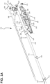
- Shaft 110 includes a distal end 118, an intermediate portion 120, and a proximal end 122 relative to handle portion 108.
- Distal end 118 includes a flexible tip 124 and proximal end 122 includes a tube engagement portion 126.
- dimensions of shaft 110 e.g., length, outside diameter, and inside diameter
- flexible tip 124 of endoscope 102 is introduced into the body cavity being inspected (such as the patient's mouth).
- a camera module and light source module are provided at distal end 118 of shaft 110 so as to capture and transmit images of the distal end 118 and corresponding patient anatomy to video monitor 106 via data cable 104.
- data cable 104 may include one or more components of the image capturing element, such as a serializer component.
- the data cable 104 may further include one or more logical components configured to identify when an endoscope has been connected, which endoscope has been connected, and to negotiate with video monitor 106 to determine which of the data cable 104 and the video monitor 106 have the most up-to-date camera settings for use during image capture.
- the combination of the data cable 104 and the endoscope 102 may together perform functions corresponding to a reusable endoscope.
- Video monitor 106 may provide power to and initiate image capture from endoscope 102 via data cable 104.
- video monitor 106 may include a display 128, and a control pad 130. Practitioners (e.g., medical personnel) may interface with video monitor 106 during use to initiate image capture, freeze a particular frame, or adjust certain limited settings.
- video monitor 106 may also include a data cable interface for receiving an end of data cable 104, a battery or other power source, and a remote monitor interface for enabling the view of display 128 to be transmitted to one or more other display monitors.
- shaft 110 may be formed of a number of discrete components.
- proximal and intermediate portions 122/120 of shaft 110 may be formed of a braided, semi-rigid polymer material having a single lumen therethrough, sized to accommodate the internal components described below.
- Flexible tip 124 in contrast, may be formed of an extruded polymer material profile formed to include three distinct lumens and cut to provide single-plane flexibility.
- Figs. 3B and 3C are isometric views of distal end 118 of endoscope shaft 110 in partially assembled and assembled configurations, respectively. As shown, distal end 118 includes flexible tip 124, an image capturing sub-assembly 306, and coupling rings 308.
- flexible tip 124 further includes a pair of opposing (i.e., 180° apart) longitudinally spaced webs 310.
- each web 310 is further positioned 90° relative to its respective pull wire lumen 304. The above-described relationship between webs 310 and pull wire lumens 304 allows for symmetric in-plane bi-directional articulation.
- webs 310 are formed by laser cutting the extruded polymer material of flexible tip 124.
- flexible tip 124 is such a small thin-walled polymer part
- a traditional laser cutting system is not capable of cutting such a part without melting the polymer. Accordingly, webs 310 are formed by using an ultrashort, pulse laser system.
- Image capturing sub-assembly 306 includes a housing 312, camera module 314, and light source module 316.
- Housing 312 may include a length of substantially cylindrical polymeric material that includes a plurality of apertures therein for receiving camera module 312, light source module 316 and working channel 206.
- an outside diameter of housing 312 may be sized to fit within an inside diameter of a distal coupling ring 308.
- housing 312 may be secured, e.g., via adhesive (e.g., Loctite ® , etc.) to the distal coupling ring 308.
- adhesive e.g., Loctite ® , etc.
- the components of image capturing sub-assembly 306 may be potted with a curable adhesive, such as an ultraviolet light curable adhesive, after assembly.
- each of housing 312 and coupling rings 308 may be keyed, as shown in Figs. 3A and 3B , to prevent twisting of housing 312 relative to coupling ring 308 during assembly.
- camera module 314 and light source module 316 may be formed as part of a circuit board assembly, such as a printed circuit board assembly (PCBA), flexible printed circuit board assembly (FPCBA), or rigid flexible printed circuit board assembly (RFPCBA) (not shown).
- the PCBA (or FPCBA/RFPCBA) may be configured to couple camera module 114 and light source module 116 to data interface assembly 205 via electrical wires 214 ( Fig. 2B ) that extend the length of endoscope 102.
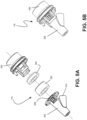
- FIGs. 5A and 5B are exploded and cross-sectional detailed views of access port assembly 116 consistent with embodiments described herein.
- access port assembly 116 includes a housing 500, a tube fitting portion 502, and seal portions 504 and 506.
- Housing 500 is a generally tubular structure formed of a rigid or semi-rigid material and includes engagement features that correspond to engagement structures provided in right and left shells 200/202.
- housing 500 includes a peripheral channel configured to engage generally u-shaped projections in right and left shells 200/202.
- Seal portions 502/504 are formed of a resilient material and include respective apertures aligned with first inlet 508 and housing 500. The size of the respective apertures is consistent with the potential uses for access port assembly, such as corresponding to particular sizes of medical tubing, instrument diameters, etc.
- Seal 502 is normally closed, and therefore allows for suction functionality as described below to occur entirely from the distal end of the working channel 206.
- Seal 504 provides an airtight seal with accessories such as a luer lock connector (e.g., syringe) or similar when used in the access port assembly 116, while seal 502 is opened by such accessories to gain access to working channel 206. This functionality, for example, enables connecting a syringe into the access port assembly 116 so that fluids can be administered into the working channel 206 without leakage.
- suction valve assembly 114 is also configured for insertion between right shell 200 and left shell 202 during assembly and operatively couples an external source of suction to working channel 206 via suction connector 224 and tube fitting 502 described above.
- Fig. 6A is an exploded detailed view of suction valve assembly 114 consistent with embodiments described herein.
- Figs. 6B and 6C are cross-sectional detailed views of suction valve assembly 114 in closed and open states, respectively.
- suction valve assembly 114 includes a housing 600, bottom cover 602, plunger 604, O-ring seal 606, spring 608, washer seal 610, and valve button 612.
- Housing 600 is a generally tubular structure formed of a rigid or semi-rigid material and includes engagement features that correspond to engagement structures provided in right and left shells 200/202.
- housing 600 includes a peripheral channel in an intermediate portion thereof configured to engage a generally u-shaped projection in right and left shells 200/202.
- suction valve assembly 114 is placed between right and left shells 200/202.
- housing 600 further includes an upper chamber 614, a lower chamber 616, an upper aperture 618, a central aperture 620, a lower aperture 622, an outlet 624, and an inlet 626.
- Outlet 624 is fluidly coupled with upper chamber 614, while inlet 626 is fluidly coupled with lower chamber 616.
- Upper and lower chambers 614/616 are fluidly coupled by central aperture 620, which is sized to allow plunger 604 to move therethrough, as described below.
- Outlet 624 is configured to project outwardly from housing 600 adjacent upper chamber 614 to receive a source of negative pressure (suction). As shown in Fig.
- an outer surface of outlet 624 may include a plurality of ribs or barbs 628 for engaging and sealing with a suction tube that is pushed thereon.
- Inlet 626 is configured project outwardly from housing 600 adjacent lower chamber 616 and sized to receive a proximal end of suction connector 224 therein, as shown in Figs. 2A and 2B .
- Bottom cover 602 is configured to be received within and enclose lower chamber 616 and includes a central cavity 630 therein for receiving a lower portion of plunger 604 during actuation of valve 114. Furthermore, as shown in Figs. 6B and 6C , bottom cover 602 further includes a groove or channel 632 for receiving O-ring seal 606, which prevents suction from affecting other components in the interior of handle 108.
- Valve button 612 engages an upper end of plunger 604 and includes a lower portion that is received within upper aperture 618.
- a space or gap 636 formed between valve button 612 and housing 600 allows any suction from outlet 624 to be applied outside of endoscope 102 via upper chamber 614 and upper aperture 618, while washer seal 610 prevents the suction from being applied to lower chamber 616 and inlet 626.
- valve button 612 is depressed, plunger 604 moves downwardly with respect to housing 600, thereby moving washer seal 610 away from central aperture 620, and thereby allowing negative pressure to be applied to lower chamber 616 and inlet 626.
- valve button 612 includes a lower portion and an upper portion 640 and an upper portion 642 that extends radially outwardly with respect to lower portion 640. As shown in Figs. 6C , a bottom surface of upper portion 642 is configured to seal upper aperture 618 when valve assembly 114 is in the closed state.
- pull wires 208 extend through shaft 120 proximal and intermediate portions 122/120 of shaft 110 and couple to control wheel assembly 204. More particularly, in one implementation, as shown in Figs. 2A and 2B , proximal ends of pull wires 208 and 210 are secured to termination elements 209 and 211, respectively. As described more fully below, termination elements 209 and 211 may include generally cylindrical or disc-shaped elements configured to be received and retained within control wheel assembly 204. Termination elements 209 and 211 may be formed of any suitable material, such as plastic, a metal, etc. and may be secured to pull wires 208 and 210 in any suitable manner, such as via welding, an adhesive, soldering, brazing, crimping, etc.
- Figs. 7A and 7B are detailed partially exploded and cross-sectional views, respectively, illustrating a portion of right shell 200.
- right shell 200 is provided with a coil stop receptacle 700 positioned generally along a center line of right shell 200 (e.g., aligned with the central aperture of tubular shaft entry portion 414) and sized to securely receive a coil stop 702.
- coil stop receptacle 700 is formed integrally with right shell 200, while in other embodiments, coil stop receptacle 700 is formed separately and is secured to right shell 200 during assembly or manufacture, such as via adhesive, welding, screws, etc.
- Coil stop 702 is formed of a resilient or semi-rigid material and is sized to fit within coil stop receptacle 700 and be retained therein via a friction fit. As shown in Fig. 7A , coil stop 702 includes a pair of slots 704 formed in a top surface thereof for receiving pull wires 208/210. As shown in Figs. 7A and 7B , consistent with embodiments described herein, each pull wire 208/210 includes a Bowden-style cable having an inner wire 706 an outer compression coil (which is an incompressible spring) 708. Compression coil 708 extends between coil stop 702 and flexible tip 124, while inner wire 706 extends between control wheel assembly 204 and flexible tip 124 distal end.
- pull wire termination element 211 may be initially inserted into wire fixing aperture 856.
- wire fixing aperture 856 may include a wire entry slot to facilitate entry of terminal element 211 and pull wire 210 into wire fixing aperture 856.
- central aperture 850 may be placed loosely onto second central shaft 812 of first control wheel 800, in a spaced relationship relative to engagement ring 820 of first control wheel 800.
- Second central shaft 812 of first control wheel 800 projects inwardly from central flange region 810 concentrically with first central shaft 808. As shown in Fig. 2A and described in additional detail below, second central shaft 812 is configured to receive a central aperture in third control wheel 804 to affect concentric alignment of third control wheel 804 with first control wheel 800 (and second control wheel 804).
- central shaft 848 of third control wheel 804 includes a generally tubular configuration having an inside surface 856 therein. As described above, during assembly, second central shaft 812 projects into central shaft 848. The relationship between inside surface 856 of central shaft 848 and the outside surface of second central shaft 812 of first control wheel 800 is configured to receive secondary control wheel boss 227 therebetween, upon assembly of left shell 202 to right shell 200.
- control wheels 800/804 less than three control wheels may be used.
- second control wheel 802 e.g., an attachment mechanism for control lever 112, etc.
- control wheels 800/804 may be integrated into one or more of control wheels 800/804. In this manner, independent tensioning of control wheels 800/804 may be maintained.
- control wheel assembly 204 may include or support electrical tensioning and/or control.
- a small electric motor e.g., a servo motor
- the electric motor may be configured to engage first central shaft 808.
- the motor may be mounted to right shell 200 adjacent to or in lieu of main control wheel boss 226. Control of such a motor could be performed using one or more switches or actuators mounted on device handle 108.
- endoscope 102 may be a single use or disposable device. As such, it may be beneficial to simplify the components of endoscope 102 to reduce the cost of the device.
- endoscope system 100 may include alternative processing capabilities that decrease the cost and complexity of the disposable portion, e.g., endoscope 102.
- Fig. 9 illustrates a simplified exemplary configuration of one or more components 900 of endoscope system 100, such as endoscope 102, data cable 104, and video monitor 106.
- component 900 may include bus 910, a processing unit 920, a memory 930, an input device 940, an output device 950, and a communication interface 960.
- Bus 910 may include a path that permits communication among the components 900 of endoscope system 100.
- bus 910 may include an I 2 C bus which supports a master/slave relationship between components 900. As described below, in exemplary implementations, the master and slave roles may be negotiated between the components, or alternatively, between multi-use devices, such as data cable 104 and video monitor 106.
- Input device 940 may include a mechanism that permits a user to input information to endoscope system 100, such as a keyboard, a keypad, a mouse, a pen, a microphone, a touch screen, voice recognition and/or biometric mechanisms, etc.
- Output device 950 may include a mechanism that outputs information to the user, including a display (e.g., a liquid crystal display (LCD)), a data interface assembly (e.g., port), a printer, a speaker, etc.
- a touch screen display may act as both an input device and an output device.
- endoscope 102 and data cable 104 may be implemented as headless devices that are not directly provided with input device 940 or output device 950 and may receive commands from, for example, video monitor 106.
- Communication interface 960 may include one or more transceivers that endoscope system 100 (e.g., video monitor 106) uses to communicate with other devices via wired, wireless or optical mechanisms.
- communication interface 960 may include a modem or an Ethernet interface to a local area network (LAN) or other mechanisms for communicating with elements in a communication network (not shown in Fig. 1 ).
- communication interface 960 may include one or more radio frequency (RF) transmitters, receivers and/or transceivers and one or more antennas for transmitting and receiving RF data via a communication network, such as a wireless LAN or Wi-Fi network.
- RF radio frequency
- endoscope system 100 may include more or fewer components than illustrated in Fig. 9 .
- endoscope system 100 performs operations in response to one or more processing units 920 executing sequences of instructions contained in a computer-readable medium, such as memory 990.
- a computer-readable medium may be defined as a physical or logical memory device.
- the software instructions may be read into memory 990 from another computer-readable medium (e.g., a hard disk drive (HDD), SSD, etc.), or from another device via communication interface 960.
- HDD hard disk drive
- SSD etc.
- hard-wired circuitry may be used in place of or in combination with software instructions to implement processes consistent with the implementations described herein.
- implementations described herein are not limited to any specific combination of hardware circuitry and software.
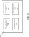
- Fig. 10 is an exemplary functional block diagram of components implemented in a single-use endoscope 102 in accordance with an embodiment described herein. In the embodiment of Fig. 10 , all or some of the components may be implemented by processing unit 920 executing software instructions stored in memory 990.
- endoscope 102 may include identification and authentication logic 1005, version checking logic 1010, settings storage 1015, data logger 1020, light source logic 1025, image capture logic 1030, and image output logic 1035.
- Identification and authentication logic 1005 is configured to, upon power up of endoscope 102, exchange identification and authentication information with data cable 104 and/or video monitor 106.
- endoscope 102 may communicate identification information to data cable 104 via bus 910 (e.g., the I 2 C bus).
- the identification information may comprise information relating to the type of endoscope 102, such as the size, application, model, particular video format, etc.
- the identification information may include information specific to the particular endoscope 102, such as serial number or other uniquely identifying information.
- Version checking logic 1010 is configured to, in coordination with similar logic in data cable 104 and video monitor 106, determine which component has a most recently updated set of camera settings. For example, because components of medical devices may not be upgradable in the field, providing an integrated upgrade path between the separate components (e.g., separate components released at different times) provides an efficient manner for rolling out updated camera settings using only a single factory-updated component, without requiring a dedicated field update process for all components within the system.
- data cable 104 and/or video monitor 106 identify endoscope 102 and determines whether it is authentic. For example, as described above, identification and authentication logic 605 requests and receives blade identification information from endoscope 102 and determines whether endoscope 102 is authentic and, potentially, that it has not exceeded its authorized number of uses. If not (block 1304 - NO), the process may end and a notification or alert is output via video monitor 106 (block 1305). In other embodiments, unauthorized devices for which a video path can be determined may be permitted to transmit video to video monitor, and, accordingly, in such embodiments, processing for unidentified or unauthorized devices may proceed to block 1312, described below.
Landscapes
- Health & Medical Sciences (AREA)
- Life Sciences & Earth Sciences (AREA)
- Surgery (AREA)
- Physics & Mathematics (AREA)
- Optics & Photonics (AREA)
- Engineering & Computer Science (AREA)
- Biomedical Technology (AREA)
- General Health & Medical Sciences (AREA)
- Pathology (AREA)
- Nuclear Medicine, Radiotherapy & Molecular Imaging (AREA)
- Biophysics (AREA)
- Heart & Thoracic Surgery (AREA)
- Medical Informatics (AREA)
- Molecular Biology (AREA)
- Animal Behavior & Ethology (AREA)
- Radiology & Medical Imaging (AREA)
- Public Health (AREA)
- Veterinary Medicine (AREA)
- Astronomy & Astrophysics (AREA)
- General Physics & Mathematics (AREA)
- Manufacturing & Machinery (AREA)
- Endoscopes (AREA)
- Instruments For Viewing The Inside Of Hollow Bodies (AREA)
Claims (9)
- Endoskopvorrichtung (102), umfassend:einen Griff (108);einen Schaft (110), der aus dem Griff herausragt,wobei der Schaft einen proximalen Abschnitt und einen distalen Abschnitt relativ zum Griff beinhaltet;eine Schlaucheingriffsvorrichtung (126) angrenzend an ein distales Ende des Griffs zum Befestigen eines Vorrichtungsschlauchs über dem Schaft vor der Verwendung,wobei die Schlaucheingriffsvorrichtung Folgendes umfasst:einen inneren Schlauchabschnitt (402) zum Aufnehmen des Schafts darin; undeinen äußeren Schlauchabschnitt (404), der konzentrisch über dem inneren Schlauchabschnitt gebildet ist,wobei ein Innendurchmesser des äußeren Schlauchabschnitts dazu konfiguriert ist, mit einem Außendurchmesser des Vorrichtungsschlauchs reibschlüssig in Eingriff zu gelangen, und wobei der Innendurchmesser des äußeren Schlauchabschnitts von dem Außendurchmesser des inneren Schlauchabschnitts beabstandet ist, sodass ein Außendurchmesser des inneren Schlauchabschnitts dazu konfiguriert ist, nicht mit einem Innendurchmesser des Vorrichtungsschlauchs in Eingriff zu gelangen;eine flexible Spitze (124), die mit dem distalen Abschnitt des Schafts verbunden ist; undein Paar von Ziehkabeln (208, 210), die vom Griffabschnitt durch den Schaftabschnitt verlaufen und mit der flexiblen Spitze verbunden sind,wobei der Griffabschnitt eine Steuerradanordnung (204) umfasst, die mit dem Paar von Ziehkabeln verbunden ist,wobei die Steuerradanordnung mindestens zwei Steuerräder (800, 802) umfasst undwobei jedes der mindestens zwei Steuerräder zu einer unabhängigen Rotation in der Lage ist, um ein exaktes Spannen des Paars von Ziehkabeln während des Zusammenbaus der Endoskopvorrichtung zu gewährleisten.
- Endoskopvorrichtung nach Anspruch 1, wobei ein Innendurchmesser des äußeren Schlauchabschnitts ein oder mehrere Eingriffsmittel umfasst, um mit dem Außendurchmesser des Vorrichtungsschlauchs reibschlüssig in Eingriff zu gelangen.
- Endoskopvorrichtung nach Anspruch 2, wobei die Eingriffsmittel mindestens eines der Folgenden umfassen: Rippen, Erhebungen oder Rasten.
- Endoskopvorrichtung nach Anspruch 2, wobei eine Vorderkante eines oder mehrerer des inneren Schlauchabschnitts oder des äußeren Schlauchabschnitts eine Fase umfasst.
- Endoskopvorrichtung nach Anspruch 1, wobei die Schlaucheingriffsvorrichtung aus einem elastischen oder halbstarren Material gebildet ist.
- Endoskopvorrichtung nach Anspruch 1, wobei die mindestens zwei Steuerräder ein erstes Steuerrad zum Verbinden mit einem ersten Ziehkabel des Paars von Ziehkabeln und ein zweites Steuerrad zum Verbinden mit einem zweiten Ziehkabel des Paars von Ziehkabeln umfassen,wobei das erste Steuerrad konzentrisch relativ zu dem zweiten Steuerrad positioniert ist,wobei, während des Zusammenbaus, das erste und das zweite Steuerrad in entgegengesetzte Richtungen relativ zueinander gedreht werden, um das Spannen durchzuführen, undwobei, nach dem Spannen, das erste und das zweite Steuerrad drehend miteinander verbunden werden, sodass eine Bewegung eines Steuerhebels bewirkt, dass sich sowohl das erste als auch das zweite Steuerrad gemeinsam drehen.
- Endoskopvorrichtung nach Anspruch 6, wobei das erste und das zweite Steuerrad jeweils ringförmige Nuten an ihrem Umfang beinhalten, um das erste und das zweite Ziehkabel aufzunehmen.
- Endoskopvorrichtung nach Anspruch 7, wobei die Steuerradanordnung ein drittes Steuerrad umfasst, das drehbar zwischen dem ersten und dem zweiten Steuerrad verbunden ist, wobei das dritte Steuerrad einen Steuerhebeleingriffsabschnitt beinhaltet.
- Endoskopvorrichtung nach Anspruch 8, wobei das dritte Steuerrad einen bogenförmigen Abschnitt beinhaltet, der zumindest einen Abschnitt des ersten und des zweiten Steuerrads abdeckt, um zu verhindern, dass externe Verunreinigungen in den Griff angrenzend an den Steuerhebel eindringen, und um ferner zu verhindern, dass das erste und das zweite Ziehkabel aus den ringförmigen Nuten am Umfang des ersten und des zweiten Steuerrads herausspringen.
Applications Claiming Priority (2)
| Application Number | Priority Date | Filing Date | Title |
|---|---|---|---|
| US201862673268P | 2018-05-18 | 2018-05-18 | |
| EP19174661.9A EP3598932B1 (de) | 2018-05-18 | 2019-05-15 | Endoskopsystem mit einer an zugdrähten verbundenen lenkradeinheit |
Related Parent Applications (1)
| Application Number | Title | Priority Date | Filing Date |
|---|---|---|---|
| EP19174661.9A Division EP3598932B1 (de) | 2018-05-18 | 2019-05-15 | Endoskopsystem mit einer an zugdrähten verbundenen lenkradeinheit |
Publications (2)
| Publication Number | Publication Date |
|---|---|
| EP3854292A1 EP3854292A1 (de) | 2021-07-28 |
| EP3854292B1 true EP3854292B1 (de) | 2025-07-02 |
Family
ID=66554276
Family Applications (6)
| Application Number | Title | Priority Date | Filing Date |
|---|---|---|---|
| EP21163741.8A Active EP3854292B1 (de) | 2018-05-18 | 2019-05-15 | Videoendoskop mit flexibler spitze |
| EP21163734.3A Active EP3861919B1 (de) | 2018-05-18 | 2019-05-15 | Videoendoskop mit flexibler spitze |
| EP21163738.4A Active EP3865045B1 (de) | 2018-05-18 | 2019-05-15 | Videoendoskop mit flexibler spitze |
| EP19174661.9A Active EP3598932B1 (de) | 2018-05-18 | 2019-05-15 | Endoskopsystem mit einer an zugdrähten verbundenen lenkradeinheit |
| EP25163167.7A Pending EP4544983A3 (de) | 2018-05-18 | 2019-05-15 | Videoendoskop mit flexibler spitze |
| EP21163739.2A Pending EP3854291A1 (de) | 2018-05-18 | 2019-05-15 | Videoendoskop mit flexibler spitze |
Family Applications After (5)
| Application Number | Title | Priority Date | Filing Date |
|---|---|---|---|
| EP21163734.3A Active EP3861919B1 (de) | 2018-05-18 | 2019-05-15 | Videoendoskop mit flexibler spitze |
| EP21163738.4A Active EP3865045B1 (de) | 2018-05-18 | 2019-05-15 | Videoendoskop mit flexibler spitze |
| EP19174661.9A Active EP3598932B1 (de) | 2018-05-18 | 2019-05-15 | Endoskopsystem mit einer an zugdrähten verbundenen lenkradeinheit |
| EP25163167.7A Pending EP4544983A3 (de) | 2018-05-18 | 2019-05-15 | Videoendoskop mit flexibler spitze |
| EP21163739.2A Pending EP3854291A1 (de) | 2018-05-18 | 2019-05-15 | Videoendoskop mit flexibler spitze |
Country Status (5)
| Country | Link |
|---|---|
| US (3) | US11800971B2 (de) |
| EP (6) | EP3854292B1 (de) |
| AU (1) | AU2019203477B2 (de) |
| CA (2) | CA3227205A1 (de) |
| ES (1) | ES2870373T3 (de) |
Families Citing this family (19)
| Publication number | Priority date | Publication date | Assignee | Title |
|---|---|---|---|---|
| EP3836826B1 (de) * | 2018-08-17 | 2024-02-21 | Cook Medical Technologies LLC | Endoskop mit steuerung der spitzenablenkung |
| USD936221S1 (en) * | 2018-10-02 | 2021-11-16 | Ambu A/S | Endoscope handle |
| CN113966190B (zh) * | 2019-05-01 | 2025-08-29 | 波士顿科学国际有限公司 | 医疗装置的腔体手柄 |
| CN110367907B (zh) * | 2019-08-07 | 2024-04-12 | 湖南省华芯医疗器械有限公司 | 一种内窥镜的手持端 |
| EP4090223B1 (de) * | 2020-01-15 | 2025-06-25 | Entellect Medical Holdings | Endoskopsteuergriff mit einer lenkanordnung |
| US11426055B2 (en) | 2020-02-21 | 2022-08-30 | Ambu A/S | Medical visualisation system including a monitor and a graphical user interface therefore |
| EP3903660A1 (de) * | 2020-04-30 | 2021-11-03 | Ambu A/S | Verfahren zur montage eines endoskopsteuersystems |
| US12402782B2 (en) | 2020-04-30 | 2025-09-02 | Ambu A/S | Endoscope control system |
| US11324394B2 (en) | 2020-09-15 | 2022-05-10 | Ambu A/S | Endoscope |
| CN216675693U (zh) * | 2021-01-08 | 2022-06-07 | 北冰洋天诺贸易有限公司 | 一种抽吸阀门和内窥镜 |
| JP2024511447A (ja) * | 2021-03-24 | 2024-03-13 | ボストン サイエンティフィック サイムド,インコーポレイテッド | 内視鏡ハンドル及び展開デバイス |
| DE102021109025A1 (de) | 2021-04-12 | 2022-10-13 | Karl Storz Se & Co. Kg | Handstück für ein flexibles Endoskop oder für ein flexibles endoskopisches Instrument |
| WO2023052237A1 (en) * | 2021-09-28 | 2023-04-06 | Ambu A/S | An endoscope |
| EP4190223B1 (de) | 2021-12-01 | 2025-02-12 | Ambu A/S | Endoskopgriff mit rahmen und verfahren zum zusammenbau |
| EP4190224A1 (de) * | 2021-12-01 | 2023-06-07 | Ambu A/S | Endoskopgriff mit rahmen |
| FR3131188B1 (fr) * | 2021-12-23 | 2024-05-10 | Axess Vision Tech | Procédé d’assemblage pour une poignée de commande d’un endoscope médical |
| EP4520246A1 (de) | 2023-09-05 | 2025-03-12 | Ambu A/S | Endoskop mit saugventil |
| EP4483778A1 (de) * | 2023-06-28 | 2025-01-01 | Ambu A/S | Handgriff für ein endoskop |
| CN117958725B (zh) * | 2024-04-01 | 2024-06-18 | 湖南省华芯医疗器械有限公司 | 一种吸引阀、内窥镜手柄和内窥镜 |
Family Cites Families (77)
| Publication number | Priority date | Publication date | Assignee | Title |
|---|---|---|---|---|
| US4207873A (en) * | 1977-05-16 | 1980-06-17 | American Cystoscope Makers, Inc. | Endoscope deflection control |
| JPS5878639A (ja) * | 1981-11-04 | 1983-05-12 | オリンパス光学工業株式会社 | 内視鏡 |
| JPS6389138A (ja) * | 1986-10-03 | 1988-04-20 | オリンパス光学工業株式会社 | 内視鏡用弯曲管外皮 |
| EP0489937B1 (de) * | 1990-12-07 | 1995-06-21 | Willy Rüsch Ag | Medizinisches Instrument mit lenkbarer Spitze |
| US5609563A (en) | 1991-12-12 | 1997-03-11 | Olympus Optical Co., Ltd. | Endoscope apparatus provided with curvature and fluid flow control |
| US5462527A (en) | 1993-06-29 | 1995-10-31 | C.R. Bard, Inc. | Actuator for use with steerable catheter |
| US5554098A (en) * | 1993-02-26 | 1996-09-10 | Olympus Optical Co., Ltd. | Endoscope system including endoscope and disposable protection cover |
| JPH07289514A (ja) * | 1994-04-25 | 1995-11-07 | I L:Kk | 内視鏡の先端レンズ洗浄管 |
| FR2785132B1 (fr) | 1998-10-27 | 2000-12-22 | Tokendo Sarl | Sonde videoendoscopique a capteur ccd couleur distal |
| US6468203B2 (en) | 2000-04-03 | 2002-10-22 | Neoguide Systems, Inc. | Steerable endoscope and improved method of insertion |
| JP2002078674A (ja) | 2000-09-08 | 2002-03-19 | Fuji Photo Optical Co Ltd | 内視鏡の湾曲部構造 |
| US6793622B2 (en) | 2001-09-05 | 2004-09-21 | Olympus Optical Co., Ltd. | Electric bending endoscope |
| US8723936B2 (en) | 2002-03-12 | 2014-05-13 | Karl Storz Imaging, Inc. | Wireless camera coupling with rotatable coupling |
| JP4026744B2 (ja) * | 2002-03-22 | 2007-12-26 | フジノン株式会社 | 内視鏡用吸引バルブ |
| US6852078B2 (en) * | 2002-05-22 | 2005-02-08 | Pentax Corporation | Outer sheathed endoscope |
| US20040199052A1 (en) | 2003-04-01 | 2004-10-07 | Scimed Life Systems, Inc. | Endoscopic imaging system |
| JP4323209B2 (ja) | 2003-04-25 | 2009-09-02 | オリンパス株式会社 | 電動湾曲内視鏡 |
| US7758497B2 (en) * | 2003-06-20 | 2010-07-20 | Contura A/S | Endoscopic attachment device |
| US7530946B2 (en) | 2003-08-15 | 2009-05-12 | Scimed Life Systems, Inc. | Compact endoscope |
| US7025721B2 (en) * | 2004-01-29 | 2006-04-11 | Boston Scientific Scimed, Inc. | Endoscope channel cap |
| US8858425B2 (en) | 2004-09-24 | 2014-10-14 | Vivid Medical, Inc. | Disposable endoscope and portable display |
| US8827899B2 (en) | 2004-09-24 | 2014-09-09 | Vivid Medical, Inc. | Disposable endoscopic access device and portable display |
| US7789826B2 (en) | 2004-09-30 | 2010-09-07 | Boston Scientific Scimed, Inc. | Manually controlled endoscope |
| TW200630066A (en) | 2005-02-23 | 2006-09-01 | Chung Shan Inst Of Science | Disposable two-stage endoscope |
| GB2425424B (en) | 2005-04-22 | 2010-09-29 | Single Use Surgical Ltd | Disposable flexible endoscope |
| US20070225556A1 (en) | 2006-03-23 | 2007-09-27 | Ethicon Endo-Surgery, Inc. | Disposable endoscope devices |
| US20070232858A1 (en) * | 2006-03-31 | 2007-10-04 | Boston Scientific Scimed, Inc. | Steering system tension control devices |
| US8992470B2 (en) * | 2006-05-19 | 2015-03-31 | Boston Scientific Scimed, Inc. | Control mechanism for steerable medical device |
| JP2008110071A (ja) | 2006-10-30 | 2008-05-15 | Olympus Corp | 内視鏡の湾曲部構造 |
| EP2190341A2 (de) | 2007-07-26 | 2010-06-02 | Avantis Medical Systems, Inc. | Endoskopsystem |
| US7789862B2 (en) | 2007-09-05 | 2010-09-07 | Thorne Consulting & Intellectual Property, LLC | Multi-chamber, sequentially dispensing syringe |
| US8152715B2 (en) | 2007-09-14 | 2012-04-10 | Optim, Incorporated | Endoscope with internal light source and power supply |
| US20090076329A1 (en) | 2007-09-17 | 2009-03-19 | Wei Su | Disposable Stereoscopic Endoscope System |
| JP2009119064A (ja) * | 2007-11-15 | 2009-06-04 | Olympus Corp | カバー式内視鏡、カバー用内視鏡および内視鏡カバー |
| FR2926715B1 (fr) * | 2008-01-24 | 2010-03-26 | Tokendo | Dispositif de commande d'un bequillage d'endoscope |
| DE102008017300A1 (de) | 2008-03-31 | 2009-10-01 | Karl Storz Gmbh & Co. Kg | Medizinisches Instrument mit arretierbarer Abwinkelsteuerung |
| US8047236B2 (en) | 2008-09-12 | 2011-11-01 | Boston Scientific Scimed, Inc. | Flexible conduit with locking element |
| WO2010044862A1 (en) | 2008-10-17 | 2010-04-22 | Ai Medical Devices, Inc. | Endotracheal intubation device |
| ES2551131T3 (es) | 2008-12-10 | 2015-11-16 | Ambu A/S | Endoscopio que tiene un receptáculo de cámara y procedimiento para fabricar un receptáculo de cámara |
| WO2010066789A1 (en) | 2008-12-10 | 2010-06-17 | Ambu A/S | Endoscope bending section control mechanism |
| WO2010066788A2 (en) | 2008-12-10 | 2010-06-17 | Ambu A/S | Endoscope with a bending portion |
| US20100249639A1 (en) | 2009-01-20 | 2010-09-30 | Samir Bhatt | Airway management devices, endoscopic conduits, surgical kits, and methods of using the same |
| US8419623B2 (en) | 2009-01-28 | 2013-04-16 | Cani Optical Systems, Llc | Portable endoscope for diverse medical disciplines |
| US9179831B2 (en) | 2009-11-30 | 2015-11-10 | King Systems Corporation | Visualization instrument |
| WO2011066760A1 (zh) | 2009-12-02 | 2011-06-09 | 武汉佑康科技有限公司 | 组合式软硬质内窥镜 |
| US20150011830A1 (en) | 2010-08-27 | 2015-01-08 | Massachusetts Institute Of Technology | Tip actuated disposable endoscope |
| US9888832B2 (en) | 2010-09-24 | 2018-02-13 | Blink Device LLC | Endotracheal intubation device |
| DE102011106386A1 (de) | 2011-07-04 | 2013-01-10 | Karl Storz Gmbh & Co. Kg | Endoskopische Anordnung |
| JP6239509B2 (ja) * | 2011-08-15 | 2017-11-29 | アトリキュア インクAtricure Inc. | 外科装置 |
| EP2830478B1 (de) | 2012-03-27 | 2019-08-21 | Medigus Ltd. | Integrierte endoskopbewässerung |
| DE102012205598A1 (de) * | 2012-04-04 | 2013-10-10 | Henke-Sass, Wolf Gmbh | Schutzhülse für ein ein Endoskoprohr aufweisendes Endoskop |
| DE102012106755A1 (de) | 2012-07-25 | 2014-01-30 | Karl Storz Gmbh & Co. Kg | Endoskop |
| US9636481B2 (en) * | 2012-09-27 | 2017-05-02 | Boston Scientific Scimed, Inc. | Steerable catheter with brake assembly |
| US9107628B2 (en) | 2012-10-12 | 2015-08-18 | Karl Storz Gmbh & Co. Kg | Video laryngoscope with disposable blade |
| DE102012111290A1 (de) | 2012-11-22 | 2014-05-22 | Karl Storz Gmbh & Co. Kg | Ein Endoskop mit einstellbarer Blickrichtung |
| WO2014106511A1 (en) | 2013-01-07 | 2014-07-10 | Ambu A/S | An articulated tip part for an endoscope |
| CN104955376B (zh) * | 2013-01-21 | 2018-04-27 | G.I.视频有限公司 | 一体式操纵装置 |
| CN105050477A (zh) * | 2013-02-22 | 2015-11-11 | 安布股份有限公司 | 用于保持内窥镜中拉紧的牵引线的装置 |
| US9375550B2 (en) * | 2013-03-15 | 2016-06-28 | St. Jude Medical, Atrial Fibrillation Division, Inc. | Catheter actuators providing mechanical advantage |
| US20140275763A1 (en) | 2013-03-15 | 2014-09-18 | Lucent Medical Systems, Inc. | Partially disposable endoscopic device |
| US9095682B2 (en) * | 2013-04-30 | 2015-08-04 | St. Jude Medical Luxembourg Holding S.À.R.L. | Control handles for catheters |
| CN105431093B (zh) | 2013-08-06 | 2019-03-29 | 奥林巴斯株式会社 | 气腹装置 |
| WO2015029718A1 (ja) | 2013-08-28 | 2015-03-05 | オリンパスメディカルシステムズ株式会社 | 挿入機器及び内視鏡 |
| US20150099927A1 (en) | 2013-10-03 | 2015-04-09 | Ali Sadoughi | Devices, systems and methods for improved intubation and management of airways |
| US8928746B1 (en) | 2013-10-18 | 2015-01-06 | Stevrin & Partners | Endoscope having disposable illumination and camera module |
| EP3047786A4 (de) * | 2013-11-07 | 2017-07-05 | Olympus Corporation | Endoskop |
| WO2015098210A1 (ja) * | 2013-12-24 | 2015-07-02 | オリンパス株式会社 | 内視鏡用シース |
| US20160000301A1 (en) | 2014-07-02 | 2016-01-07 | Xenocor, Inc. | Borescopes and related methods and systems |
| US9943214B2 (en) | 2014-07-02 | 2018-04-17 | Xenocor, Inc. | Medical borescopes and related methods and systems |
| US10959868B2 (en) * | 2014-09-15 | 2021-03-30 | Cook Medical Technologies, LLC | Ratchet operated vascular intervention device delivery system |
| US10646107B2 (en) * | 2015-05-27 | 2020-05-12 | Ambu A/S | Endoscope with a tool |
| US9931487B2 (en) * | 2015-08-06 | 2018-04-03 | Boston Scientific Scimed, Inc. | Bidirectional steering control apparatus for a catheter |
| CN109069799B (zh) * | 2016-04-08 | 2021-07-16 | 圣犹达医疗用品心脏病学部门有限公司 | 标测可调环圈导管手柄 |
| KR102229513B1 (ko) * | 2016-07-28 | 2021-03-18 | 쿡 메디컬 테크놀러지스 엘엘씨 | 조향 가능 카테터 핸들 |
| US20180028784A1 (en) * | 2016-07-28 | 2018-02-01 | Cook Medical Technolgoies Llc | Control wire distal securement in steerable catheter |
| EP3592200B1 (de) * | 2017-03-08 | 2023-11-08 | Ambu A/S | Griff für ein endoskop |
| TWI659728B (zh) * | 2017-11-02 | 2019-05-21 | 國立交通大學 | 具末端轉向機構的微創手術用具 |
-
2019
- 2019-05-15 EP EP21163741.8A patent/EP3854292B1/de active Active
- 2019-05-15 EP EP21163734.3A patent/EP3861919B1/de active Active
- 2019-05-15 EP EP21163738.4A patent/EP3865045B1/de active Active
- 2019-05-15 EP EP19174661.9A patent/EP3598932B1/de active Active
- 2019-05-15 ES ES19174661T patent/ES2870373T3/es active Active
- 2019-05-15 EP EP25163167.7A patent/EP4544983A3/de active Pending
- 2019-05-15 EP EP21163739.2A patent/EP3854291A1/de active Pending
- 2019-05-17 US US16/415,145 patent/US11800971B2/en active Active
- 2019-05-17 CA CA3227205A patent/CA3227205A1/en active Pending
- 2019-05-17 CA CA3043908A patent/CA3043908C/en active Active
- 2019-05-17 AU AU2019203477A patent/AU2019203477B2/en active Active
-
2023
- 2023-09-28 US US18/477,077 patent/US20240023793A1/en active Pending
-
2024
- 2024-08-02 US US18/793,144 patent/US20240389838A1/en active Pending
Also Published As
| Publication number | Publication date |
|---|---|
| EP4544983A2 (de) | 2025-04-30 |
| US20240023793A1 (en) | 2024-01-25 |
| EP3854291A1 (de) | 2021-07-28 |
| EP3598932A3 (de) | 2020-04-22 |
| US20190350440A1 (en) | 2019-11-21 |
| US11800971B2 (en) | 2023-10-31 |
| EP3865045B1 (de) | 2025-05-14 |
| EP3598932B1 (de) | 2021-03-31 |
| ES2870373T3 (es) | 2021-10-26 |
| AU2019203477A1 (en) | 2019-12-05 |
| EP3598932A2 (de) | 2020-01-29 |
| EP4544983A3 (de) | 2025-08-06 |
| CA3043908C (en) | 2024-03-19 |
| CA3043908A1 (en) | 2019-11-18 |
| AU2019203477B2 (en) | 2021-04-08 |
| EP3861919B1 (de) | 2025-05-14 |
| EP3865045A1 (de) | 2021-08-18 |
| EP3854292A1 (de) | 2021-07-28 |
| US20240389838A1 (en) | 2024-11-28 |
| CA3227205A1 (en) | 2019-11-18 |
| EP3861919A1 (de) | 2021-08-11 |
Similar Documents
| Publication | Publication Date | Title |
|---|---|---|
| US20240389838A1 (en) | Video endoscope with flexible tip | |
| US11253141B2 (en) | Handheld surgical endoscope | |
| US11019987B2 (en) | Endoscope having shaft rotatably connected to handle | |
| US11903562B2 (en) | Encasement platform for smartdevice for attachment to endoscope | |
| US20180326144A1 (en) | Endoscope system and method of use | |
| US20220192471A1 (en) | Detachable shafts for endoscopes | |
| KR20200094797A (ko) | 패닝가능한 카메라를 구비한 내시경 | |
| US20210186307A1 (en) | Endoscope with detachable camera module | |
| US11889992B2 (en) | Endoscope and method of use | |
| JP2024500321A (ja) | 内視鏡システム及びアセンブリ | |
| JP7273830B2 (ja) | 耳下手術のための可視化デバイス | |
| JP6937439B2 (ja) | 内視鏡補助具及び内視鏡 | |
| JP7326098B2 (ja) | 内視鏡用送液装置、送液チューブ及び送液装置本体 | |
| HK40016333A (en) | Endoscope system with a control wheel assembly coupled to pull wires | |
| HK40016333B (en) | Endoscope system with a control wheel assembly coupled to pull wires | |
| EP2574270A1 (de) | Verschlussvorrichtung für die Endöffnung eines Endoskops | |
| KR20200059556A (ko) | 내시경 카테터 조립체 | |
| JP2004129720A (ja) | 内視鏡装置 |
Legal Events
| Date | Code | Title | Description |
|---|---|---|---|
| PUAI | Public reference made under article 153(3) epc to a published international application that has entered the european phase |
Free format text: ORIGINAL CODE: 0009012 |
|
| STAA | Information on the status of an ep patent application or granted ep patent |
Free format text: STATUS: THE APPLICATION HAS BEEN PUBLISHED |
|
| AC | Divisional application: reference to earlier application |
Ref document number: 3598932 Country of ref document: EP Kind code of ref document: P |
|
| AK | Designated contracting states |
Kind code of ref document: A1 Designated state(s): AL AT BE BG CH CY CZ DE DK EE ES FI FR GB GR HR HU IE IS IT LI LT LU LV MC MK MT NL NO PL PT RO RS SE SI SK SM TR |
|
| STAA | Information on the status of an ep patent application or granted ep patent |
Free format text: STATUS: REQUEST FOR EXAMINATION WAS MADE |
|
| 17P | Request for examination filed |
Effective date: 20220127 |
|
| RBV | Designated contracting states (corrected) |
Designated state(s): AL AT BE BG CH CY CZ DE DK EE ES FI FR GB GR HR HU IE IS IT LI LT LU LV MC MK MT NL NO PL PT RO RS SE SI SK SM TR |
|
| P01 | Opt-out of the competence of the unified patent court (upc) registered |
Effective date: 20230527 |
|
| GRAP | Despatch of communication of intention to grant a patent |
Free format text: ORIGINAL CODE: EPIDOSNIGR1 |
|
| STAA | Information on the status of an ep patent application or granted ep patent |
Free format text: STATUS: GRANT OF PATENT IS INTENDED |
|
| INTG | Intention to grant announced |
Effective date: 20241218 |
|
| GRAS | Grant fee paid |
Free format text: ORIGINAL CODE: EPIDOSNIGR3 |
|
| GRAA | (expected) grant |
Free format text: ORIGINAL CODE: 0009210 |
|
| STAA | Information on the status of an ep patent application or granted ep patent |
Free format text: STATUS: THE PATENT HAS BEEN GRANTED |
|
| AC | Divisional application: reference to earlier application |
Ref document number: 3598932 Country of ref document: EP Kind code of ref document: P |
|
| AK | Designated contracting states |
Kind code of ref document: B1 Designated state(s): AL AT BE BG CH CY CZ DE DK EE ES FI FR GB GR HR HU IE IS IT LI LT LU LV MC MK MT NL NO PL PT RO RS SE SI SK SM TR |
|
| REG | Reference to a national code |
Ref country code: GB Ref legal event code: FG4D |
|
| REG | Reference to a national code |
Ref country code: CH Ref legal event code: EP |
|
| REG | Reference to a national code |
Ref country code: DE Ref legal event code: R096 Ref document number: 602019072163 Country of ref document: DE |
|
| REG | Reference to a national code |
Ref country code: IE Ref legal event code: FG4D |
|
| REG | Reference to a national code |
Ref country code: NL Ref legal event code: FP |
|
| PG25 | Lapsed in a contracting state [announced via postgrant information from national office to epo] |
Ref country code: PT Free format text: LAPSE BECAUSE OF FAILURE TO SUBMIT A TRANSLATION OF THE DESCRIPTION OR TO PAY THE FEE WITHIN THE PRESCRIBED TIME-LIMIT Effective date: 20251103 |
|
| REG | Reference to a national code |
Ref country code: AT Ref legal event code: MK05 Ref document number: 1808266 Country of ref document: AT Kind code of ref document: T Effective date: 20250702 |
|
| PG25 | Lapsed in a contracting state [announced via postgrant information from national office to epo] |
Ref country code: IS Free format text: LAPSE BECAUSE OF FAILURE TO SUBMIT A TRANSLATION OF THE DESCRIPTION OR TO PAY THE FEE WITHIN THE PRESCRIBED TIME-LIMIT Effective date: 20251102 |
|
| PG25 | Lapsed in a contracting state [announced via postgrant information from national office to epo] |
Ref country code: NO Free format text: LAPSE BECAUSE OF FAILURE TO SUBMIT A TRANSLATION OF THE DESCRIPTION OR TO PAY THE FEE WITHIN THE PRESCRIBED TIME-LIMIT Effective date: 20251002 |
|
| REG | Reference to a national code |
Ref country code: LT Ref legal event code: MG9D |
|
| PG25 | Lapsed in a contracting state [announced via postgrant information from national office to epo] |
Ref country code: AT Free format text: LAPSE BECAUSE OF FAILURE TO SUBMIT A TRANSLATION OF THE DESCRIPTION OR TO PAY THE FEE WITHIN THE PRESCRIBED TIME-LIMIT Effective date: 20250702 |
|
| PG25 | Lapsed in a contracting state [announced via postgrant information from national office to epo] |
Ref country code: FI Free format text: LAPSE BECAUSE OF FAILURE TO SUBMIT A TRANSLATION OF THE DESCRIPTION OR TO PAY THE FEE WITHIN THE PRESCRIBED TIME-LIMIT Effective date: 20250702 |
|
| PG25 | Lapsed in a contracting state [announced via postgrant information from national office to epo] |
Ref country code: HR Free format text: LAPSE BECAUSE OF FAILURE TO SUBMIT A TRANSLATION OF THE DESCRIPTION OR TO PAY THE FEE WITHIN THE PRESCRIBED TIME-LIMIT Effective date: 20250702 |
|
| PG25 | Lapsed in a contracting state [announced via postgrant information from national office to epo] |
Ref country code: GR Free format text: LAPSE BECAUSE OF FAILURE TO SUBMIT A TRANSLATION OF THE DESCRIPTION OR TO PAY THE FEE WITHIN THE PRESCRIBED TIME-LIMIT Effective date: 20251003 |
|
| PG25 | Lapsed in a contracting state [announced via postgrant information from national office to epo] |
Ref country code: SE Free format text: LAPSE BECAUSE OF FAILURE TO SUBMIT A TRANSLATION OF THE DESCRIPTION OR TO PAY THE FEE WITHIN THE PRESCRIBED TIME-LIMIT Effective date: 20250702 Ref country code: CZ Free format text: LAPSE BECAUSE OF FAILURE TO SUBMIT A TRANSLATION OF THE DESCRIPTION OR TO PAY THE FEE WITHIN THE PRESCRIBED TIME-LIMIT Effective date: 20250702 |
|
| PG25 | Lapsed in a contracting state [announced via postgrant information from national office to epo] |
Ref country code: LV Free format text: LAPSE BECAUSE OF FAILURE TO SUBMIT A TRANSLATION OF THE DESCRIPTION OR TO PAY THE FEE WITHIN THE PRESCRIBED TIME-LIMIT Effective date: 20250702 |
|
| PG25 | Lapsed in a contracting state [announced via postgrant information from national office to epo] |
Ref country code: PL Free format text: LAPSE BECAUSE OF FAILURE TO SUBMIT A TRANSLATION OF THE DESCRIPTION OR TO PAY THE FEE WITHIN THE PRESCRIBED TIME-LIMIT Effective date: 20250702 Ref country code: BG Free format text: LAPSE BECAUSE OF FAILURE TO SUBMIT A TRANSLATION OF THE DESCRIPTION OR TO PAY THE FEE WITHIN THE PRESCRIBED TIME-LIMIT Effective date: 20250702 |
|
| PG25 | Lapsed in a contracting state [announced via postgrant information from national office to epo] |
Ref country code: RS Free format text: LAPSE BECAUSE OF FAILURE TO SUBMIT A TRANSLATION OF THE DESCRIPTION OR TO PAY THE FEE WITHIN THE PRESCRIBED TIME-LIMIT Effective date: 20251002 |
|
| PG25 | Lapsed in a contracting state [announced via postgrant information from national office to epo] |
Ref country code: ES Free format text: LAPSE BECAUSE OF FAILURE TO SUBMIT A TRANSLATION OF THE DESCRIPTION OR TO PAY THE FEE WITHIN THE PRESCRIBED TIME-LIMIT Effective date: 20250702 |