EP3853595B1 - Détecteur électromagnétique permettant la détection de propriétés de produits de l'industrie du tabac - Google Patents
Détecteur électromagnétique permettant la détection de propriétés de produits de l'industrie du tabac Download PDFInfo
- Publication number
- EP3853595B1 EP3853595B1 EP19801412.8A EP19801412A EP3853595B1 EP 3853595 B1 EP3853595 B1 EP 3853595B1 EP 19801412 A EP19801412 A EP 19801412A EP 3853595 B1 EP3853595 B1 EP 3853595B1
- Authority
- EP
- European Patent Office
- Prior art keywords
- emitting
- receiving
- detector
- initial
- shell
- Prior art date
- Legal status (The legal status is an assumption and is not a legal conclusion. Google has not performed a legal analysis and makes no representation as to the accuracy of the status listed.)
- Active
Links
- 241000208125 Nicotiana Species 0.000 title claims description 42
- 235000002637 Nicotiana tabacum Nutrition 0.000 title claims description 42
- 239000000523 sample Substances 0.000 claims description 57
- 239000000047 product Substances 0.000 claims description 38
- 230000005672 electromagnetic field Effects 0.000 claims description 26
- 239000011265 semifinished product Substances 0.000 claims description 23
- 238000001514 detection method Methods 0.000 claims description 14
- 239000002245 particle Substances 0.000 claims description 9
- 239000011810 insulating material Substances 0.000 claims description 3
- 230000001419 dependent effect Effects 0.000 claims 1
- 238000004140 cleaning Methods 0.000 description 75
- 239000000463 material Substances 0.000 description 18
- 238000009826 distribution Methods 0.000 description 14
- 239000000126 substance Substances 0.000 description 11
- 239000012530 fluid Substances 0.000 description 9
- 239000002775 capsule Substances 0.000 description 8
- 230000005684 electric field Effects 0.000 description 8
- 235000019504 cigarettes Nutrition 0.000 description 7
- 238000007689 inspection Methods 0.000 description 7
- 239000000428 dust Substances 0.000 description 6
- 239000000725 suspension Substances 0.000 description 5
- 230000008878 coupling Effects 0.000 description 4
- 238000010168 coupling process Methods 0.000 description 4
- 238000005859 coupling reaction Methods 0.000 description 4
- 238000004519 manufacturing process Methods 0.000 description 4
- 238000005259 measurement Methods 0.000 description 3
- 239000000443 aerosol Substances 0.000 description 2
- 230000007547 defect Effects 0.000 description 2
- 239000007789 gas Substances 0.000 description 2
- 229920001903 high density polyethylene Polymers 0.000 description 2
- 239000004700 high-density polyethylene Substances 0.000 description 2
- 239000007788 liquid Substances 0.000 description 2
- 238000004458 analytical method Methods 0.000 description 1
- 230000004888 barrier function Effects 0.000 description 1
- 230000008859 change Effects 0.000 description 1
- 239000003795 chemical substances by application Substances 0.000 description 1
- 235000019506 cigar Nutrition 0.000 description 1
- 230000001143 conditioned effect Effects 0.000 description 1
- 230000002950 deficient Effects 0.000 description 1
- 239000003571 electronic cigarette Substances 0.000 description 1
- 239000000835 fiber Substances 0.000 description 1
- 238000000265 homogenisation Methods 0.000 description 1
- 230000006872 improvement Effects 0.000 description 1
- 238000009413 insulation Methods 0.000 description 1
- 230000007257 malfunction Effects 0.000 description 1
- 239000013528 metallic particle Substances 0.000 description 1
- 238000000034 method Methods 0.000 description 1
- 239000000203 mixture Substances 0.000 description 1
- 238000005457 optimization Methods 0.000 description 1
- 238000012858 packaging process Methods 0.000 description 1
- 230000008569 process Effects 0.000 description 1
- 230000001737 promoting effect Effects 0.000 description 1
- 230000001681 protective effect Effects 0.000 description 1
- 230000005855 radiation Effects 0.000 description 1
- 230000009467 reduction Effects 0.000 description 1
- 238000011144 upstream manufacturing Methods 0.000 description 1
Images


Classifications
-
- G—PHYSICS
- G01—MEASURING; TESTING
- G01N—INVESTIGATING OR ANALYSING MATERIALS BY DETERMINING THEIR CHEMICAL OR PHYSICAL PROPERTIES
- G01N22/00—Investigating or analysing materials by the use of microwaves or radio waves, i.e. electromagnetic waves with a wavelength of one millimetre or more
- G01N22/04—Investigating moisture content
-
- A—HUMAN NECESSITIES
- A24—TOBACCO; CIGARS; CIGARETTES; SIMULATED SMOKING DEVICES; SMOKERS' REQUISITES
- A24C—MACHINES FOR MAKING CIGARS OR CIGARETTES
- A24C5/00—Making cigarettes; Making tipping materials for, or attaching filters or mouthpieces to, cigars or cigarettes
- A24C5/32—Separating, ordering, counting or examining cigarettes; Regulating the feeding of tobacco according to rod or cigarette condition
- A24C5/34—Examining cigarettes or the rod, e.g. for regulating the feeding of tobacco; Removing defective cigarettes
- A24C5/3412—Examining cigarettes or the rod, e.g. for regulating the feeding of tobacco; Removing defective cigarettes by means of light, radiation or electrostatic fields
Definitions
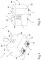
- the detector 1 comprises an emitting probe 4 for creating the field and a receiving probe 5 to receive a field altered by the presence of the product.
- the emitting probe 4 and the receiving probe 5 are positioned inside the detector 1.
- the emitting probe 4 and the receiving probe 5 have an angled shape and comprise, respectively, a terminal emitting portion 401 and a terminal receiving portion 501 which are parallel to the direction of the detection field.
- terminal emitting portion 401 and the terminal receiving portion 501 are filiform-shaped and parallel to each other.
- the electromagnetic detector 1 comprises a body 8, which is hollow and is provided with a base wall 801, an emitting half-shell 802 and a receiving half-shell 803.
- the emitting half-shell 802 and the receiving half-shell 803 extend from the base wall 801.
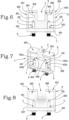
- the dielectric sheath 9 comprises a bottom zone 901 forming part of the bottom wall 201.
- the dielectric sheath 9 comprises an emitting zone 902 and a receiving zone 903 which face each other to define, in between them, a detecting chamber forming part of the detecting channel 2 in which the field is located, as described in more detail below.
- the dielectric sheath 9 internally delimits in the detector 1 an emitting cavity 805 in the emitting half-shell 802 and a receiving cavity 806 in the receiving half-shell 803.
- the dielectric sheath 9 extends as far as the base wall 801 and makes contact with the base wall 801.
- the dielectric sheath 9 is fixed to the body 8 in zones unaffected by the electromagnetic field and is not in contact with the base wall 801.
- the dielectric sheath 9 allows noticeable improvement of the efficiency and effectiveness of the detector 1, since it provides a protective barrier which prevents the access of unwanted external agents, for example dust, into the emitting cavity 805 and the receiving cavity 806, defines the detecting chamber and allows optimization of the measuring process by promoting concentration and homogenization of the radiation transmitted by the emitting probe 4 inside the detecting chamber, also optimizing its reception by the receiving probe 5.
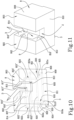
- the body 8 additionally comprises an emitting side wall 807 and a receiving side wall 808 which face each other, extend from the base wall 801 and laterally delimit the emitting half-shell 802 and the receiving half-shell 803, respectively.
- the initial emitting portion 402 and the initial receiving portion 502 are close to the rear wall 810. However, there must not be any contact between each filiform-shaped first stretch 402a, 502a (or the entire initial emitting portion 402 and the entire initial receiving portion if they are entirely filiform-shaped) and the rear wall 810. Preferably, the distance between each filiform-shaped first stretch 402a, 502a and the rear wall 810 is equal to at least 0.5 mm.
- the terminal emitting portion 401 and the terminal receiving portion 501 are positioned to face towards the front wall 809.
- the terminal emitting portion 401 and the terminal receiving portion 501 are linear.
- the terminal emitting portion 401 and the terminal receiving portion 501 have a length included in a range from 0.5 mm to a maximum length where each terminal portion 401, 501 extends until near the front wall 809 (without touching it).
- the detector 1 may be installed in an apparatus forming part of a machine of the tobacco industry.
- the apparatus may comprise a belt conveyor (not illustrated) configured to hold and convey the semi-finished product along a conveying path which comprises a guide channel (not illustrated) delimited at the sides by two side walls and at the top by a belt, perforated or porous, preferably a suction belt (not illustrated).
- a belt conveyor (not illustrated) configured to hold and convey the semi-finished product along a conveying path which comprises a guide channel (not illustrated) delimited at the sides by two side walls and at the top by a belt, perforated or porous, preferably a suction belt (not illustrated).
- the detecting channel 2 is configured to slidably receive, in the pass-through direction D, at least one portion of the suction belt and at least one portion of the semi-finished product held on the belt.
- the detecting channel 2 is also configured to receive guide elements (not illustrated) of the side walls of the conveyor, which delimit the suction belt in a localized way, that is to say, at the detecting channel 2.
- the detector 1 comprises a body 8, which is hollow and comprises a base wall 801, an emitting half-shell 802 and a receiving half-shell 803, which extend from the base wall 801.
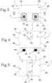
- the cleaning circuit 811 comprises at least a first cleaning opening 812 in the emitting half-shell 802, or the receiving half-shell 803, to deliver compressed air from the emitting half-shell 802, or the receiving half-shell 803.
- the second cleaning opening 813 delivers, preferably, an air jet directed towards the detecting channel 2 so that there is cleaning from both of the half-shells 802, 803 of the detecting channel 2.
- the first cleaning opening 812 and the second cleaning opening 813 lie in a first plane perpendicular to the pass-through direction D so that they face each other.
- the first cleaning opening 812 and the second cleaning opening 813 are aligned, so as to obtain symmetrically emitted air jets in the detecting channel 2.
- the cleaning circuit comprises a third cleaning opening 814 in the emitting half-shell 802, or the receiving half-shell 803, to deliver compressed air from the emitting half-shell 802, or the receiving half-shell 803, and a fourth cleaning opening 815 in the receiving half-shell 803, or the emitting half-shell 802, to deliver compressed air from the receiving half-shell 803, or the emitting half-shell 802.
- the third cleaning opening 814 and the fourth cleaning opening 815 lie in a second plane perpendicular to the pass-through direction D so that they face each other.
- the third cleaning opening 814 and the fourth cleaning opening 815 are also aligned, so as to obtain symmetrically emitted air jets in the detecting channel 2.
- the first cleaning opening 812, the second cleaning opening 813, the third cleaning opening 814 and the fourth cleaning opening 815 all lie in the same plane parallel to the pass-through direction D and also parallel to the bottom wall 201 of the detecting channel.
- the first cleaning opening 812, the second cleaning opening 813, the third cleaning opening 814 and the fourth cleaning opening 815 are near to the bottom wall 201 of the detecting channel 2.
- Those openings 812, 813, 814, 815 are preferably circular but may also be shaped like a crack, or shaped differently, with regard to the cleaning flow to be obtained.
- the detector 1 comprises an emitting wall 202 and a receiving wall 203 which face each other and laterally delimit the detecting channel 2.
- the emitting wall 202 and the receiving wall 203 extend from the bottom wall 201.
- the emitting wall 202 comprises a pair of external emitting portions 816', 816" of the emitting half-shell 802.
- the receiving wall 203 comprises a pair of external receiving portions 817', 817" of the receiving half-shell 803.
- the emitting zone 902 is located between the external emitting portions 816', 816
- the receiving zone 903 is located between the external receiving portions 817', 817".
- the external emitting portions 816', 816" are located at the sides of the emitting zone 902
- the external receiving portions 817', 817" are located at the sides of the receiving zone 903.
- the external emitting portions 816', 816" face the external receiving portions 817', 817" and define a first pair of facing external portions 816'; 817', and a second pair of facing external portions 816"; 817", respectively.
- the first cleaning opening 812 is located in one of the external emitting portions 816', or 816"; or in one of the external receiving portions 817', 817".
- the first cleaning opening 812 and the second cleaning opening 813 are located in the first pair of external portions 816', 817'.
- the third cleaning opening 814 and the fourth cleaning opening 815 are located in the second pair of external portions 816", 817".
- the feed connector 3 is positioned alongside the emitting connector 6 and the receiving connector 7 in the base wall 801 and therefore the detector 1 has a single wall, the base wall 801, set up for external connections.
- the cleaning circuit 811 is also configured to deliver compressed air internally, into the emitting cavity 805 of the emitting half-shell 802 and into the receiving cavity 806 of the receiving half-shell 803, in such a way as to maintain an overpressure in them.
- the internal emitting opening 824 and the internal receiving opening 825 are connected, respectively, to the third straight stretch and to the fourth straight stretch of the inlet section 820 which are respectively positioned at the emitting half-shell 802 and the receiving half-shell 803.
- the cleaning circuit 811 delivers into the detecting channel 2 cleaning air jets capable of creating a longitudinal cleaning flow directed towards the outside of the detecting channel 2, capable of conveying out of the detecting channel 2 any extraneous bodies present in it and capable of preventing any further extraneous bodies in suspension from accessing the detecting channel 2.
- the cleaning flow acts between the emitting wall 202 and one guide element and between the receiving wall 203 and the other guide element.
- the cleaning circuit 811 creates an overpressure in the emitting cavity 805 and in the receiving cavity 806 to prevent extraneous bodies from being able to enter and remain trapped in internal parts of the detector 1.
Landscapes
- Physics & Mathematics (AREA)
- General Health & Medical Sciences (AREA)
- Health & Medical Sciences (AREA)
- Biochemistry (AREA)
- Chemical & Material Sciences (AREA)
- Analytical Chemistry (AREA)
- Life Sciences & Earth Sciences (AREA)
- Electromagnetism (AREA)
- General Physics & Mathematics (AREA)
- Immunology (AREA)
- Pathology (AREA)
- Toxicology (AREA)
- Manufacturing Of Cigar And Cigarette Tobacco (AREA)
Claims (16)
- Détecteur électromagnétique (1) permettant la détection d'une ou plusieurs propriétés d'un produit, par exemple un article en forme de tige, ou d'un produit semi-fini de l'industrie du tabac, comprenant un canal de détection (2) qui est ouvert sur trois côtés pour permettre au produit de passer à travers le détecteur électromagnétique (1) le long d'une direction de passage (D), dans lequel dans le canal de détection (2) est situé un champ électromagnétique orienté dans une direction de détection parallèle à la direction de passage (D) ; dans lequel le détecteur électromagnétique (1) comprend une sonde émettrice (4) pour créer le champ électromagnétique et une sonde réceptrice (5) pour recevoir un champ électromagnétique modifié par la présence du produit, les sondes (4 ; 5) étant positionnées à l'intérieur du détecteur électromagnétique (1), caractérisé en ce que la sonde émettrice (4) et la sonde réceptrice (5) comprennent, respectivement, une portion émettrice terminale (401) et une portion réceptrice terminale (501) qui sont parallèles à la direction du champ de détection, et une portion émettrice initiale (402) et une portion réceptrice initiale (502) connectant le détecteur (1) à l'extérieur ; et dans lequel la portion émettrice initiale (402) forme un angle avec la portion émettrice terminale (401), la portion réceptrice initiale (502) forme un angle avec la portion réceptrice terminale (501), dans lequel la portion émettrice initiale (402) et la portion réceptrice initiale (502) sont droites, et chacune s'étend le long d'un axe d'extension unique respectif.
- Détecteur selon la revendication 1, dans lequel la portion émettrice terminale (401) et la portion réceptrice terminale (501) sont de forme filiforme et parallèles l'une à l'autre.
- Détecteur selon la revendication 1 ou 2, dans lequel la portion émettrice terminale (401) et la portion réceptrice terminale (501) ont la même longueur.
- Détecteur selon une ou plusieurs des revendications précédentes, et comprenant un connecteur d'émission externe (6) et un connecteur de réception externe (7) pour connecter le détecteur électromagnétique (1) à un émetteur et à un récepteur d'une unité de commande, respectivement, et dans lequel la portion émettrice initiale (402) et la portion réceptrice initiale (502) connectent, respectivement, la portion émettrice terminale (401) au connecteur émetteur externe (6) et la portion réceptrice terminale (501) au connecteur récepteur externe (7).
- Détecteur selon une ou plusieurs des revendications précédentes, dans lequel chaque portion initiale (402 ; 502) entre la portion émettrice initiale (401) et la portion réceptrice initiale (501) comprend un premier tronçon respectif (402a ; 502a), qui est de forme filiforme et connecté à la portion terminale respective (401 ; 501), et un second tronçon respectif (402b, 502b), qui est entouré par un matériau isolant et connecté au connecteur externe respectif (6 ; 7).
- Détecteur selon une ou plusieurs des revendications précédentes, dans lequel la portion émettrice initiale (402) et la portion réceptrice initiale (502) sont perpendiculaires à la portion émettrice terminale (401) et à la portion réceptrice terminale (501), respectivement.
- Détecteur selon une ou plusieurs des revendications précédentes, dans lequel la portion émettrice initiale (402) et la portion réceptrice initiale (502) sont parallèles l'une à l'autre et se trouvent dans un seul second plan qui est perpendiculaire à un premier plan dans lequel se trouvent la portion émettrice terminale (401) et la portion réceptrice terminale (501).
- Détecteur selon une ou plusieurs des revendications précédentes, dans lequel le détecteur électromagnétique (1) comprend un corps (8) qui est creux et comprend une paroi de base (801), une demi-coquille émettrice (802) et une demi-coquille réceptrice (803) qui s'étendent à partir de la paroi de base (801) ; une gaine diélectrique (9) logée dans le corps (8) et interposée au centre entre la demi-coquille émettrice (802) et la demi-coquille réceptrice (803) et qui est entourée par la demi-coquille émettrice (802) et par la demi-coquille réceptrice (803) ; dans lequel la gaine diélectrique (9) délimite intérieurement une cavité émettrice (805) dans la demi-coquille émettrice (802) et une cavité réceptrice (806) dans la demi-coquille réceptrice (803), la sonde émettrice (4) étant positionnée dans la cavité émettrice (805) et la sonde réceptrice (5) étant positionnée dans la cavité réceptrice (806).
- Détecteur selon la revendication 8, lorsqu'elle dépend de l'une quelconque des revendications 4 à 7, dans lequel le connecteur émetteur externe (6) et le connecteur récepteur externe (7) sont fixés à la paroi de base (801).
- Détecteur selon la revendication 8 ou 9, dans lequel la gaine diélectrique (9) comprend un panneau émetteur (902) qui délimite au moins partiellement la cavité émettrice (805) et un panneau récepteur (903) qui délimite au moins partiellement la cavité réceptrice (806) et dans lequel la portion émettrice initiale (402) est proche du panneau émetteur (902) et la portion réceptrice initiale (502) est proche du panneau récepteur (903).
- Détecteur selon la revendication 10, lorsque celle-ci est rattachée à l'une quelconque des revendications 5 à 7, dans lequel le second tronçon (402b) de la portion émettrice initiale (402) est en contact avec le panneau émetteur (902) et le second tronçon (502b) de la portion réceptrice initiale (502) est en contact avec le panneau récepteur (903).
- Détecteur selon une ou plusieurs des revendications 8 à 11, dans lequel le détecteur électromagnétique (1) comprend une paroi latérale émettrice (807) et une paroi latérale réceptrice (808), qui se font face, s'étendent depuis la paroi de base (801) et délimitent latéralement la demi-coquille émettrice (802) et la demi-coquille réceptrice (803), respectivement, une paroi avant (809) et une paroi arrière (810), qui se font également face, s'étendent depuis la paroi de base (801), ont la forme d'un U ou d'un C et sont positionnées entre la paroi latérale émettrice (807) et la paroi latérale réceptrice (808) pour délimiter frontalement la demi-coquille émettrice (802) et la demi-coquille réceptrice (803) ; la portion émettrice initiale (402) et la portion réceptrice initiale (502) étant positionnées à proximité de la paroi arrière (810), la portion émettrice terminale (401) et la portion réceptrice terminale (501) étant positionnées pour faire face vers la paroi avant (809).
- Détecteur selon la revendication 12, dans lequel la portion émettrice terminale (401) et la portion réceptrice terminale (501) sont linéaires et ont une longueur comprise dans une plage de 0,5 mm à une longueur maximale où chaque portion terminale (401 ; 501) s'étend jusqu'à atteindre la proximité de la paroi avant (809).
- Détecteur selon une ou plusieurs des revendications 8 à 13, dans lequel la gaine diélectrique (9) comprend une zone émettrice (902) et une zone réceptrice (903) qui se font face pour définir, entre elles, une chambre de détection faisant partie du canal de détection (2) et contenant le champ électromagnétique.
- Détecteur selon l'une quelconque des revendications précédentes, dans lequel le détecteur électromagnétique (1) est un détecteur à micro-ondes et fonctionne, par exemple, à une longueur d'onde comprise entre 108 et 1012 Hz pour mesurer la densité et/ou l'humidité du produit.
- Appareil pour transporter et inspecter un produit de l'industrie du tabac, où le produit est un produit semi-fini contenant des particules de tabac, et qui comprend :- un transporteur à bande configuré pour maintenir et transporter le produit semi-fini le long d'un parcours de transport qui comprend un canal de guidage délimité sur les côtés par deux parois latérales et sur le dessus par une bande, de préférence une bande aspirante ;- un détecteur électromagnétique (1) selon l'une quelconque des revendications 1 à 15, dans lequel le canal de détection (2) est configuré pour recevoir de manière coulissante, dans la direction de passage (D), au moins une portion de la bande et au moins une portion du produit semi-fini maintenu sur la bande.
Applications Claiming Priority (2)
| Application Number | Priority Date | Filing Date | Title |
|---|---|---|---|
| IT201800008793 | 2018-09-21 | ||
| PCT/IB2019/057855 WO2020058868A1 (fr) | 2018-09-21 | 2019-09-18 | Détecteur électromagnétique permettant la détection de propriétés de produits de l'industrie du tabac |
Publications (2)
| Publication Number | Publication Date |
|---|---|
| EP3853595A1 EP3853595A1 (fr) | 2021-07-28 |
| EP3853595B1 true EP3853595B1 (fr) | 2024-07-03 |
Family
ID=64557074
Family Applications (1)
| Application Number | Title | Priority Date | Filing Date |
|---|---|---|---|
| EP19801412.8A Active EP3853595B1 (fr) | 2018-09-21 | 2019-09-18 | Détecteur électromagnétique permettant la détection de propriétés de produits de l'industrie du tabac |
Country Status (3)
| Country | Link |
|---|---|
| EP (1) | EP3853595B1 (fr) |
| PL (1) | PL3853595T3 (fr) |
| WO (1) | WO2020058868A1 (fr) |
Families Citing this family (1)
| Publication number | Priority date | Publication date | Assignee | Title |
|---|---|---|---|---|
| IT202200010922A1 (it) * | 2022-05-25 | 2023-11-25 | Gd Spa | Rilevatore elettromagnetico per la rilevazione di proprietà di prodotti dell’industria del tabacco |
Family Cites Families (4)
| Publication number | Priority date | Publication date | Assignee | Title |
|---|---|---|---|---|
| DE29711571U1 (de) * | 1997-07-02 | 1998-11-05 | Tews Elektronik Dipl.-Ing. Manfred Tews, 22459 Hamburg | Feuchte- und Dichtesensor |
| DE102011083051A1 (de) * | 2011-09-20 | 2013-03-21 | Hauni Maschinenbau Ag | Mikrowellenresonatorgehäuse |
| DE102013213936A1 (de) * | 2013-07-16 | 2015-01-22 | Hauni Maschinenbau Ag | Anordnung und Verfahren zur Überprüfung von stabförmigen Artikeln der Tabak verarbeitenden Industrie |
| DE102015119722A1 (de) * | 2015-11-16 | 2017-05-18 | Hauni Maschinenbau Gmbh | Anordnung, Maschine, Verfahren und Verwendung zum Überprüfen einer Zigarettenkopfqualität |
-
2019
- 2019-09-18 PL PL19801412.8T patent/PL3853595T3/pl unknown
- 2019-09-18 WO PCT/IB2019/057855 patent/WO2020058868A1/fr unknown
- 2019-09-18 EP EP19801412.8A patent/EP3853595B1/fr active Active
Also Published As
| Publication number | Publication date |
|---|---|
| PL3853595T3 (pl) | 2024-09-09 |
| EP3853595A1 (fr) | 2021-07-28 |
| WO2020058868A1 (fr) | 2020-03-26 |
Similar Documents
| Publication | Publication Date | Title |
|---|---|---|
| US7793664B2 (en) | Apparatus and method for detection and segregation of faulty cigarettes | |
| US20060207616A1 (en) | Detection of non-homogeneities in a continuous filter rod | |
| JP5683126B2 (ja) | カプセルを備えるフィルタロッドを監視する方法と装置 | |
| US6768317B2 (en) | Method of and apparatus for testing a first material for potential presence of second materials | |
| US20050098744A1 (en) | Process and device for measuring the length and/or the diameter of filter bars | |
| EP3853595B1 (fr) | Détecteur électromagnétique permettant la détection de propriétés de produits de l'industrie du tabac | |
| CN103504473B (zh) | 对烟草加工业的材料条的条异质性进行识别的方法和装置 | |
| US20020130670A1 (en) | Microwave-resonator and measuring device | |
| CN104287086A (zh) | 用于对烟草加工业的棒形制品进行检查的设备和方法 | |
| CN106880078B (zh) | 用于制造杆状物品的方法和系统 | |
| ITBO20060585A1 (it) | Dispositivo per la rilevazione di una caratteristica di un materiale fibroso. | |
| CN105249529B (zh) | 烟草加工行业的机器、滚筒系统及棒形制品的检测方法 | |
| CN106455678B (zh) | 微波测量装置、用于检验烟草加工业的棒形制品或材料条的组件和方法及烟草加工业的机器 | |
| CN103960774A (zh) | 用于检查烟草加工工业的棒状制品的设备和方法 | |
| US20070006655A1 (en) | Glue quantity determination | |
| JPH0928365A (ja) | タバコの複素誘電率を測定する装置 | |
| EP3853594B1 (fr) | Détecteur électromagnétique pour la détection de propriétés de produits de l'industrie du tabac | |
| KR102431953B1 (ko) | 제품의 전기전도성 요소를 검출하는 측정 장치 및 방법, 및 담배 가공 산업의 제품을 생산하는 기계 | |
| WO2015039849A1 (fr) | Appareil pour la détection d'une substance dans un article en forme de tige de l'industrie du tabac | |
| JPH06197746A (ja) | シガレットのルース端を識別するための点検方法及び装置 | |
| WO2015039851A2 (fr) | Inspection d'articles en forme de tige de l'industrie du tabac | |
| EP3806666B1 (fr) | Unité de détection et procédé pour l'industrie du tabac | |
| EP3768099B1 (fr) | Station pour le transport et l'inspection d'un produit semi-fini de l'industrie du tabac | |
| US20040237973A1 (en) | Apparatus for ascertaining the transverse dimensions of rod-shaped articles | |
| EP3720304B1 (fr) | Machine pour la production d'un boudin continu de l'industrie du tabac |
Legal Events
| Date | Code | Title | Description |
|---|---|---|---|
| STAA | Information on the status of an ep patent application or granted ep patent |
Free format text: STATUS: UNKNOWN |
|
| STAA | Information on the status of an ep patent application or granted ep patent |
Free format text: STATUS: THE INTERNATIONAL PUBLICATION HAS BEEN MADE |
|
| PUAI | Public reference made under article 153(3) epc to a published international application that has entered the european phase |
Free format text: ORIGINAL CODE: 0009012 |
|
| STAA | Information on the status of an ep patent application or granted ep patent |
Free format text: STATUS: REQUEST FOR EXAMINATION WAS MADE |
|
| 17P | Request for examination filed |
Effective date: 20210413 |
|
| AK | Designated contracting states |
Kind code of ref document: A1 Designated state(s): AL AT BE BG CH CY CZ DE DK EE ES FI FR GB GR HR HU IE IS IT LI LT LU LV MC MK MT NL NO PL PT RO RS SE SI SK SM TR |
|
| DAV | Request for validation of the european patent (deleted) | ||
| DAX | Request for extension of the european patent (deleted) | ||
| P01 | Opt-out of the competence of the unified patent court (upc) registered |
Effective date: 20230525 |
|
| GRAP | Despatch of communication of intention to grant a patent |
Free format text: ORIGINAL CODE: EPIDOSNIGR1 |
|
| STAA | Information on the status of an ep patent application or granted ep patent |
Free format text: STATUS: GRANT OF PATENT IS INTENDED |
|
| INTG | Intention to grant announced |
Effective date: 20230912 |
|
| GRAJ | Information related to disapproval of communication of intention to grant by the applicant or resumption of examination proceedings by the epo deleted |
Free format text: ORIGINAL CODE: EPIDOSDIGR1 |
|
| STAA | Information on the status of an ep patent application or granted ep patent |
Free format text: STATUS: REQUEST FOR EXAMINATION WAS MADE |
|
| INTC | Intention to grant announced (deleted) | ||
| GRAP | Despatch of communication of intention to grant a patent |
Free format text: ORIGINAL CODE: EPIDOSNIGR1 |
|
| STAA | Information on the status of an ep patent application or granted ep patent |
Free format text: STATUS: GRANT OF PATENT IS INTENDED |
|
| INTG | Intention to grant announced |
Effective date: 20240202 |
|
| GRAS | Grant fee paid |
Free format text: ORIGINAL CODE: EPIDOSNIGR3 |
|
| GRAA | (expected) grant |
Free format text: ORIGINAL CODE: 0009210 |
|
| STAA | Information on the status of an ep patent application or granted ep patent |
Free format text: STATUS: THE PATENT HAS BEEN GRANTED |
|
| AK | Designated contracting states |
Kind code of ref document: B1 Designated state(s): AL AT BE BG CH CY CZ DE DK EE ES FI FR GB GR HR HU IE IS IT LI LT LU LV MC MK MT NL NO PL PT RO RS SE SI SK SM TR |
|
| REG | Reference to a national code |
Ref country code: CH Ref legal event code: EP |