EP3852468B1 - Comportement d'ue déterministe pour rapport csi/srs pendant drx - Google Patents
Comportement d'ue déterministe pour rapport csi/srs pendant drx Download PDFInfo
- Publication number
- EP3852468B1 EP3852468B1 EP21160396.4A EP21160396A EP3852468B1 EP 3852468 B1 EP3852468 B1 EP 3852468B1 EP 21160396 A EP21160396 A EP 21160396A EP 3852468 B1 EP3852468 B1 EP 3852468B1
- Authority
- EP
- European Patent Office
- Prior art keywords
- subframe
- drx
- mobile station
- active time
- srs
- Prior art date
- Legal status (The legal status is an assumption and is not a legal conclusion. Google has not performed a legal analysis and makes no representation as to the accuracy of the status listed.)
- Active
Links
- 230000005540 biological transmission Effects 0.000 claims description 124
- 230000000737 periodic effect Effects 0.000 claims description 89
- 238000000034 method Methods 0.000 claims description 68
- 230000011664 signaling Effects 0.000 claims description 52
- 230000004044 response Effects 0.000 claims description 4
- 230000008569 process Effects 0.000 description 30
- 239000000969 carrier Substances 0.000 description 28
- 101000741965 Homo sapiens Inactive tyrosine-protein kinase PRAG1 Proteins 0.000 description 21
- 102100038659 Inactive tyrosine-protein kinase PRAG1 Human genes 0.000 description 21
- 238000012545 processing Methods 0.000 description 21
- 238000010295 mobile communication Methods 0.000 description 20
- 230000002776 aggregation Effects 0.000 description 17
- 238000004220 aggregation Methods 0.000 description 17
- 230000006399 behavior Effects 0.000 description 13
- 230000001052 transient effect Effects 0.000 description 10
- 238000010586 diagram Methods 0.000 description 8
- 238000005516 engineering process Methods 0.000 description 7
- 230000014509 gene expression Effects 0.000 description 7
- 238000001228 spectrum Methods 0.000 description 7
- 230000008859 change Effects 0.000 description 6
- 238000005259 measurement Methods 0.000 description 6
- 101150116295 CAT2 gene Proteins 0.000 description 5
- 101100326920 Caenorhabditis elegans ctl-1 gene Proteins 0.000 description 5
- 101100126846 Neurospora crassa (strain ATCC 24698 / 74-OR23-1A / CBS 708.71 / DSM 1257 / FGSC 987) katG gene Proteins 0.000 description 5
- 238000004891 communication Methods 0.000 description 5
- 125000004122 cyclic group Chemical group 0.000 description 5
- 230000006870 function Effects 0.000 description 5
- 230000007774 longterm Effects 0.000 description 5
- 239000011159 matrix material Substances 0.000 description 5
- 101100494773 Caenorhabditis elegans ctl-2 gene Proteins 0.000 description 4
- 101100112369 Fasciola hepatica Cat-1 gene Proteins 0.000 description 4
- 101100005271 Neurospora crassa (strain ATCC 24698 / 74-OR23-1A / CBS 708.71 / DSM 1257 / FGSC 987) cat-1 gene Proteins 0.000 description 4
- 238000007726 management method Methods 0.000 description 4
- 238000013468 resource allocation Methods 0.000 description 4
- 230000001960 triggered effect Effects 0.000 description 4
- 230000004913 activation Effects 0.000 description 3
- 230000006978 adaptation Effects 0.000 description 3
- 230000001965 increasing effect Effects 0.000 description 3
- 230000007246 mechanism Effects 0.000 description 3
- 238000012546 transfer Methods 0.000 description 3
- 101100383920 Fragaria ananassa MCSI gene Proteins 0.000 description 2
- 101100005280 Neurospora crassa (strain ATCC 24698 / 74-OR23-1A / CBS 708.71 / DSM 1257 / FGSC 987) cat-3 gene Proteins 0.000 description 2
- 230000009286 beneficial effect Effects 0.000 description 2
- 230000002860 competitive effect Effects 0.000 description 2
- 238000007906 compression Methods 0.000 description 2
- 230000009849 deactivation Effects 0.000 description 2
- 230000001419 dependent effect Effects 0.000 description 2
- 238000012544 monitoring process Methods 0.000 description 2
- 229920000915 polyvinyl chloride Polymers 0.000 description 2
- 230000003595 spectral effect Effects 0.000 description 2
- 238000001774 stimulated Raman spectroscopy Methods 0.000 description 2
- 230000001360 synchronised effect Effects 0.000 description 2
- 241000700159 Rattus Species 0.000 description 1
- 238000013459 approach Methods 0.000 description 1
- 238000003491 array Methods 0.000 description 1
- 238000013475 authorization Methods 0.000 description 1
- 230000008901 benefit Effects 0.000 description 1
- 230000015556 catabolic process Effects 0.000 description 1
- 230000006835 compression Effects 0.000 description 1
- 238000012790 confirmation Methods 0.000 description 1
- 230000006837 decompression Effects 0.000 description 1
- 238000006731 degradation reaction Methods 0.000 description 1
- 238000013461 design Methods 0.000 description 1
- 238000011161 development Methods 0.000 description 1
- 230000000694 effects Effects 0.000 description 1
- 230000002708 enhancing effect Effects 0.000 description 1
- 238000005562 fading Methods 0.000 description 1
- 230000036039 immunity Effects 0.000 description 1
- 230000006872 improvement Effects 0.000 description 1
- 238000003780 insertion Methods 0.000 description 1
- 230000037431 insertion Effects 0.000 description 1
- 238000012986 modification Methods 0.000 description 1
- 230000004048 modification Effects 0.000 description 1
- 238000002360 preparation method Methods 0.000 description 1
- 230000002035 prolonged effect Effects 0.000 description 1
- 230000010076 replication Effects 0.000 description 1
- 230000007480 spreading Effects 0.000 description 1
- 238000003892 spreading Methods 0.000 description 1
- 238000003860 storage Methods 0.000 description 1
- 208000037918 transfusion-transmitted disease Diseases 0.000 description 1
- 230000007704 transition Effects 0.000 description 1
- 230000002618 waking effect Effects 0.000 description 1
- 239000002699 waste material Substances 0.000 description 1
Images


Classifications
-
- H—ELECTRICITY
- H04—ELECTRIC COMMUNICATION TECHNIQUE
- H04L—TRANSMISSION OF DIGITAL INFORMATION, e.g. TELEGRAPHIC COMMUNICATION
- H04L5/00—Arrangements affording multiple use of the transmission path
- H04L5/003—Arrangements for allocating sub-channels of the transmission path
- H04L5/0048—Allocation of pilot signals, i.e. of signals known to the receiver
- H04L5/0051—Allocation of pilot signals, i.e. of signals known to the receiver of dedicated pilots, i.e. pilots destined for a single user or terminal
-
- H—ELECTRICITY
- H04—ELECTRIC COMMUNICATION TECHNIQUE
- H04W—WIRELESS COMMUNICATION NETWORKS
- H04W76/00—Connection management
- H04W76/20—Manipulation of established connections
- H04W76/28—Discontinuous transmission [DTX]; Discontinuous reception [DRX]
-
- H—ELECTRICITY
- H04—ELECTRIC COMMUNICATION TECHNIQUE
- H04L—TRANSMISSION OF DIGITAL INFORMATION, e.g. TELEGRAPHIC COMMUNICATION
- H04L5/00—Arrangements affording multiple use of the transmission path
- H04L5/003—Arrangements for allocating sub-channels of the transmission path
- H04L5/0053—Allocation of signaling, i.e. of overhead other than pilot signals
- H04L5/0057—Physical resource allocation for CQI
-
- H—ELECTRICITY
- H04—ELECTRIC COMMUNICATION TECHNIQUE
- H04W—WIRELESS COMMUNICATION NETWORKS
- H04W72/00—Local resource management
- H04W72/04—Wireless resource allocation
- H04W72/044—Wireless resource allocation based on the type of the allocated resource
- H04W72/0446—Resources in time domain, e.g. slots or frames
-
- H—ELECTRICITY
- H04—ELECTRIC COMMUNICATION TECHNIQUE
- H04W—WIRELESS COMMUNICATION NETWORKS
- H04W72/00—Local resource management
- H04W72/20—Control channels or signalling for resource management
- H04W72/21—Control channels or signalling for resource management in the uplink direction of a wireless link, i.e. towards the network
-
- H—ELECTRICITY
- H04—ELECTRIC COMMUNICATION TECHNIQUE
- H04W—WIRELESS COMMUNICATION NETWORKS
- H04W72/00—Local resource management
- H04W72/20—Control channels or signalling for resource management
- H04W72/23—Control channels or signalling for resource management in the downlink direction of a wireless link, i.e. towards a terminal
-
- H—ELECTRICITY
- H04—ELECTRIC COMMUNICATION TECHNIQUE
- H04W—WIRELESS COMMUNICATION NETWORKS
- H04W16/00—Network planning, e.g. coverage or traffic planning tools; Network deployment, e.g. resource partitioning or cells structures
- H04W16/14—Spectrum sharing arrangements between different networks
-
- H—ELECTRICITY
- H04—ELECTRIC COMMUNICATION TECHNIQUE
- H04W—WIRELESS COMMUNICATION NETWORKS
- H04W24/00—Supervisory, monitoring or testing arrangements
- H04W24/10—Scheduling measurement reports ; Arrangements for measurement reports
-
- Y—GENERAL TAGGING OF NEW TECHNOLOGICAL DEVELOPMENTS; GENERAL TAGGING OF CROSS-SECTIONAL TECHNOLOGIES SPANNING OVER SEVERAL SECTIONS OF THE IPC; TECHNICAL SUBJECTS COVERED BY FORMER USPC CROSS-REFERENCE ART COLLECTIONS [XRACs] AND DIGESTS
- Y02—TECHNOLOGIES OR APPLICATIONS FOR MITIGATION OR ADAPTATION AGAINST CLIMATE CHANGE
- Y02D—CLIMATE CHANGE MITIGATION TECHNOLOGIES IN INFORMATION AND COMMUNICATION TECHNOLOGIES [ICT], I.E. INFORMATION AND COMMUNICATION TECHNOLOGIES AIMING AT THE REDUCTION OF THEIR OWN ENERGY USE
- Y02D30/00—Reducing energy consumption in communication networks
- Y02D30/70—Reducing energy consumption in communication networks in wireless communication networks
Definitions
- the invention relates to a mobile station and a method performed by a mobile station.
- LTE Long Term Evolution
- High-Speed Downlink Packet Access HSDPA
- HSUPA High Speed Uplink Packet Access
- LTE Long Term Evolution
- LTE Long-Term Evolution
- UTRA Evolved UMTS Terrestrial Radio Access
- UTRAN UMTS Terrestrial Radio Access Network
- LTE Rel. 8 The LTE system represents efficient packet-based radio access and radio access networks that provide full IP-based functionalities with low latency and low cost.
- scalable multiple transmission bandwidths are specified such as 1.4, 3.0, 5.0, 10.0, 15.0, and 20.0 MHz, in order to achieve flexible system deployment using a given spectrum.
- Orthogonal Frequency Division Multiplexing OFDM
- OFDM Orthogonal Frequency Division Multiplexing
- SC-FDMA Single-carrier frequency division multiple access
- UE user equipment
- MIMO multiple-input multiple-output
- the E-UTRAN consists of an eNodeB, providing the E-UTRA user plane (PDCP/RLC/MAC/PHY) and control plane (RRC) protocol terminations towards the user equipment (UE).
- the eNodeB hosts the Physical (PHY), Medium Access Control (MAC), Radio Link Control (RLC) and Packet Data Control Protocol (PDCP) layers that include the functionality of user-plane header-compression and encryption. It also offers Radio Resource Control (RRC) functionality corresponding to the control plane.
- RRC Radio Resource Control
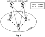
- the eNodeBs are interconnected with each other by means of the X2 interface.
- the eNodeBs are also connected by means of the S1 interface to the EPC (Evolved Packet Core), more specifically to the MME (Mobility Management Entity) by means of the S1-MME and to the Serving Gateway (SGW) by means of the S1-U.
- EPC Evolved Packet Core
- MME Mobility Management Entity
- SGW Serving Gateway
- the S1 interface supports a many-to-many relation between MMEs/Serving Gateways and eNodeBs.
- the SGW routes and forwards user data packets, while also acting as the mobility anchor for the user plane during inter-eNodeB handovers and as the anchor for mobility between LTE and other 3GPP technologies (terminating S4 interface and relaying the traffic between 2G/3G systems and PDN GW).
- the SGW terminates the downlink data path and triggers paging when downlink data arrives for the user equipment. It manages and stores user equipment contexts, e.g. parameters of the IP bearer service, network internal routing information. It also performs replication of the user traffic in case of lawful interception.
- user equipment contexts e.g. parameters of the IP bearer service, network internal routing information. It also performs replication of the user traffic in case of lawful interception.
- the MME is the key control-node for the LTE access-network. It is responsible for idle mode user equipment tracking and paging procedure including retransmissions. It is involved in the bearer activation/deactivation process and is also responsible for choosing the SGW for a user equipment at the initial attach and at time of intra-LTE handover involving Core Network (CN) node relocation. It is responsible for authenticating the user (by interacting with the HSS).
- NAS Non-Access Stratum
- the Non-Access Stratum (NAS) signaling terminates at the MME and it is also responsible for generation and allocation of temporary identities to user equipments. It checks the authorization of the user equipment to camp on the service provider's Public Land Mobile Network (PLMN) and enforces user equipment roaming restrictions.
- PLMN Public Land Mobile Network
- the MME is the termination point in the network for ciphering/integrity protection for NAS signaling and handles the security key management. Lawful interception of signaling is also supported by the MME.
- the MME also provides the control plane function for mobility between LTE and 2G/3G access networks with the S3 interface terminating at the MME from the SGSN.
- the MME also terminates the S6a interface towards the home HSS for roaming user equipments.
- the downlink component carrier of a 3GPP LTE is subdivided in the time-frequency domain in so-called subframes.
- each subframe is divided into two downlink slots as shown in Fig. 3 , wherein the first downlink slot comprises the control channel region (PDCCH region) within the first OFDM symbols.
- Each subframe consists of a give number of OFDM symbols in the time domain (12 or 14 OFDM symbols in 3GPP LTE (Release 8)), wherein each OFDM symbol spans over the entire bandwidth of the component carrier.
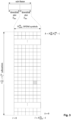
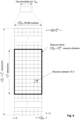
- the OFDM symbols thus each consists of a number of modulation symbols transmitted on respective N RB DL ⁇ N sc RB subcarriers as also shown in Fig. 4 .
- a physical resource block is defined as N symb DL consecutive OFDM symbols in the time domain (e.g. 7 OFDM symbols) and N sc RB consecutive subcarriers in the frequency domain as exemplified in Fig. 4 (e.g. 12 subcarriers for a component carrier).
- a physical resource block thus consists of N symb DL ⁇ N sc RB resource elements, corresponding to one slot in the time domain and 180 kHz in the frequency domain (for further details on the downlink resource grid, see for example 3GPP TS 36.211, "Evolved Universal Terrestrial Radio Access (E-UTRA); Physical Channels and Modulation (Release 8)", section 6.2, available at http://www.3gpp.org).
- One subframe consists of two slots, so that there are 14 OFDM symbols in a subframe when a so-called "normal” CP (cyclic prefix) is used, and 12 OFDM symbols in a subframe when a so-called “extended” CP is used.
- a "resource block pair” or equivalent "RB pair” or "PRB pair”.
- component carrier refers to a combination of several resource blocks in the frequency domain.
- cell refers to a combination of downlink and optionally uplink resources.
- the linking between the carrier frequency of the downlink resources and the carrier frequency of the uplink resources is indicated in the system information transmitted on the downlink resources.
- the frequency spectrum for IMT-Advanced was decided at the World Radio communication Conference 2007 (WRC-07). Although the overall frequency spectrum for IMT-Advanced was decided, the actual available frequency bandwidth is different according to each region or country. Following the decision on the available frequency spectrum outline, however, standardization of a radio interface started in the 3rd Generation Partnership Project (3GPP). At the 3GPP TSG RAN #39 meeting, the Study Item description on "Further Advancements for E-UTRA (LTE-Advanced)" was approved. The study item covers technology components to be considered for the evolution of E-UTRA, e.g. to fulfill the requirements on IMT-Advanced.
- 3GPP 3rd Generation Partnership Project
- the bandwidth that the LTE-Advanced system is able to support is 100 MHz, while an LTE system can only support 20 MHz.
- the lack of radio spectrum has become a bottleneck of the development of wireless networks, and as a result it is difficult to find a spectrum band which is wide enough for the LTE-Advanced system. Consequently, it is urgent to find a way to gain a wider radio spectrum band, wherein a possible answer is the carrier aggregation functionality.
- carrier aggregation two or more component carriers (component carriers) are aggregated in order to support wider transmission bandwidths up to 100MHz.
- component carriers component carriers
- Several cells in the LTE system are aggregated into one wider channel in the LTE-Advanced system which is wide enough for 100 MHz even though these cells in LTE are in different frequency bands.
- All component carriers can be configured to be LTE Rel. 8/9 compatible, at least when the aggregated numbers of component carriers in the uplink and the downlink are the same. Not all component carriers aggregated by a user equipment may necessarily be Rel. 8/9 compatible. Existing mechanism (e.g. barring) may be used to avoid Rel-8/9 user equipments to camp on a component carrier.
- a user equipment may simultaneously receive or transmit one or multiple component carriers (corresponding to multiple serving cells) depending on its capabilities.
- a LTE-A Rel. 10 user equipment with reception and/or transmission capabilities for carrier aggregation can simultaneously receive and/or transmit on multiple serving cells, whereas an LTE Rel. 8/9 user equipment can receive and transmit on a single serving cell only, provided that the structure of the component carrier follows the Rel. 8/9 specifications.
- Carrier aggregation is supported for both contiguous and non-contiguous component carriers with each component carrier limited to a maximum of 110 Resource Blocks in the frequency domain using the 3GPP LTE (Release 8/9) numerology.
- a 3GPP LTE-A (Release 10) compatible user equipment to aggregate a different number of component carriers originating from the same eNodeB (base station) and of possibly different bandwidths in the uplink and the downlink.
- the number of downlink component carriers that can be configured depends on the downlink aggregation capability of the UE.
- the number of uplink component carriers that can be configured depends on the uplink aggregation capability of the UE. It may not be possible to configure a mobile terminal with more uplink component carriers than downlink component carriers.
- the number of component carriers and the bandwidth of each component carrier in uplink and downlink is the same.
- Component carriers originating from the same eNodeB need not to provide the same coverage.
- the spacing between centre frequencies of contiguously aggregated component carriers shall be a multiple of 300 kHz. This is in order to be compatible with the 100 kHz frequency raster of 3GPP LTE (Release 8/9) and at the same time preserve orthogonality of the subcarriers with 15 kHz spacing. Depending on the aggregation scenario, the n ⁇ 300 kHz spacing can be facilitated by insertion of a low number of unused subcarriers between contiguous component carriers.
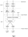
- the Layer 2 structure with activated carrier aggregation is shown in Fig. 5 and Fig. 6 for the downlink and uplink respectively.
- the mobile terminal When carrier aggregation is configured, the mobile terminal only has one RRC connection with the network.
- one cell At RRC connection establishment/re-establishment, one cell provides the security input (one ECGI, one PCI and one ARFCN) and the non-access stratum mobility information (e.g. TAI) similarly as in LTE Rel. 8/9.
- the component carrier corresponding to that cell is referred to as the downlink Primary Cell (PCell).
- PCell downlink Primary Cell
- DL PCell downlink PCell
- UL PCell uplink PCell
- SCells Secondary Cells
- DL SCC Downlink Secondary Component Carrier
- UL SCC Uplink Secondary Component Carrier
- the configuration and reconfiguration of component carriers can be performed by RRC. Activation and deactivation is done via MAC control elements.
- RRC can also add, remove, or reconfigure SCells for usage in the target cell.
- dedicated RRC signaling is used for sending the system information of the SCell, the information being necessary for transmission / reception (similarly as in Rel-8/9 for handover).
- ⁇ DL anchor carrier When a user equipment is configured with carrier aggregation there is one pair of uplink and downlink component carriers that is always active.
- the downlink component carrier of that pair might be also referred to as ⁇ DL anchor carrier'. Same applies also for the uplink.
- a user equipment When carrier aggregation is configured, a user equipment may be scheduled over multiple component carriers simultaneously but at most one random access procedure shall be ongoing at any time.
- Cross-carrier scheduling allows the PDCCH of a component carrier to schedule resources on another component carrier.
- a component carrier identification field is introduced in the respective DCI formats, called CIF.
- a linking between uplink and downlink component carriers allows identifying the uplink component carrier for which the grant applies when there is no-cross-carrier scheduling.
- the linkage of downlink component carriers to uplink component carrier does not necessarily need to be one to one. In other words, more than one downlink component carrier can link to the same uplink component carrier. At the same time, a downlink component carrier can only link to one uplink component carrier.
- LTE is based on only two main states: "RRC_IDLE” and “RRC_CONNECTED”.
- RRC_IDLE the radio is not active, but an ID is assigned and tracked by the network. More specifically, a mobile terminal in RRC_IDLE performs cell selection and reselection - in other words, it decides on which cell to camp.
- the cell (re)selection process takes into account the priority of each applicable frequency of each applicable Radio Access Technology (RAT), the radio link quality and the cell status (i.e. whether a cell is barred or reserved).
- An RRC_IDLE mobile terminal monitors a paging channel to detect incoming calls, and also acquires system information.
- the system information mainly consists of parameters by which the network (E-UTRAN) can control the cell (re)selection process.
- RRC specifies the control signalling applicable for a mobile terminal in RRC_IDLE, namely paging and system information.
- the mobile terminal behaviour in RRC_IDLE is specified in TS 36.304.
- RRC_CONNECTED the mobile terminal has an established RRC connection with contexts in the eNodeB.
- the E-UTRAN allocates radio resources to the mobile terminal to facilitate the transfer of (unicast) data via shared data channels.
- the mobile terminal monitors an associated control channel which is used to indicate the dynamic allocation of the shared transmission resources in time and frequency.
- the mobile terminal provides the network with reports of its buffer status and of the downlink channel quality, as well as neighbouring cell measurement information to enable E-UTRAN to select the most appropriate cell for the mobile terminal. These measurement reports include cells using other frequencies or RATs.
- the UE also receives system information, consisting mainly of information required to use the transmission channels.
- a UE in RRC_CONNECTED may be configured with a Discontinuous Reception (DRX) cycle.
- DRX Discontinuous Reception
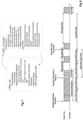
- Fig. 7 shows a state diagram with an overview of the relevant functions performed by the mobile terminal in IDLE and CONNECTED state.
- the MAC layer provides a data transfer service for the RLC layer through logical channels.
- Logical channels are either Control Logical Channels which carry control data such as RRC signalling, or Traffic Logical Channels which carry user plane data.
- Broadcast Control Channel (BCCH), Paging Control channel (PCCH), Common Control Channel (CCCH), Multicast Control Channel (MCCH) and Dedicated Control Channel (DCCH) are Control Logical Channels.
- Dedicated Traffic channel (DTCH) and Multicast Traffic Channel (MTCH) are Traffic Logical Channels.
- Transport Channels Data from the MAC layer is exchanged with the physical layer through Transport Channels. Data is multiplexed into transport channels depending on how it is transmitted over the air. Transport channels are classified as downlink or uplink as follows. Broadcast Channel (BCH), Downlink Shared Channel (DL-SCH), Paging Channel (PCH) and Multicast Channel (MCH) are downlink transport channels, whereas the Uplink Shared Channel (UL-SCH) and the Random Access Channel (RACH) are uplink transport channels.
- BCH Broadcast Channel
- DL-SCH Downlink Shared Channel
- PCH Paging Channel
- MCH Multicast Channel
- UL-SCH Uplink Shared Channel
- RACH Random Access Channel
- a multiplexing is then performed between logical channels and transport channels in the downlink and uplink respectively.
- L1/L2 control signaling is transmitted on the downlink along with the data.
- L1/L2 control signaling is multiplexed with the downlink data in a subframe, assuming that the user allocation can change from subframe to subframe.
- user allocation might also be performed on a TTI (Transmission Time Interval) basis, where the TTI length can be a multiple of the subframes.
- TTI length may be fixed in a service area for all users, may be different for different users, or may even by dynamic for each user.
- the L1/2 control signaling needs only be transmitted once per TTI. Without loss of generality, the following assumes that a TTI is equivalent to one subframe.
- the L1/L2 control signaling is transmitted on the Physical Downlink Control Channel (PDCCH).
- a PDCCH carries a message as a Downlink Control Information (DCI), which includes resource assignments and other control information for a mobile terminal or groups of UEs.
- DCI Downlink Control Information
- several PDCCHs can be transmitted in one subframe.
- uplink scheduling grants or uplink resource assignments are also transmitted on the PDCCH.
- the information sent on the L1/L2 control signaling may be separated into the following two categories, Shared Control Information (SCI) carrying Cat 1 information and Downlink Control Information (DCI) carrying Cat 2/3 information.
- SCI Shared Control Information
- DCI Downlink Control Information
- the shared control information part of the L1/L2 control signaling contains information related to the resource allocation (indication).
- the shared control information typically contains the following information:
- the shared control information may additionally contain information such as ACK/NACK for uplink transmission, uplink scheduling information, information on the DCI (resource, MCS, etc.).
- DCI Downlink Control Information
- the downlink control information part of the L1/L2 control signaling contains information related to the transmission format (Cat 2 information) of the data transmitted to a scheduled user indicated by the Cat 1 information. Moreover, in case of using (Hybrid) ARQ as a retransmission protocol, the Cat 2 information carries HARQ (Cat 3) information.
- the downlink control information needs only to be decoded by the user scheduled according to Cat 1.
- the downlink control information typically contains information on:
- Downlink control information occurs in several formats that differ in overall size and also in the information contained in its fields.
- the different DCI formats that are currently defined for LTE are described in detail in 3GPP TS 36.212, "Multiplexing and channel coding ", section 5.3.3.1 (available at http://www.3gpp.org).
- Uplink Control Information (UCI)
- uplink control signaling in mobile communication systems can be divided into two categories:
- Uplink data-associated control signaling is not necessary in LTE, as the relevant information is already known to the eNodeB. Therefore, only data-non-associated control signaling exists in the LTE uplink.
- the UCI can consist of:
- the amount of UCI a UE can transmit in a subframe depends on the number of SC-FDMA symbols available for transmission of control signaling data.
- the PUCCH supports eight different formats, depending on the amount of information to be signaled.
- the following UCI formats on PUCCH are supported, according to the following overview PUCCH Format Uplink Control Information (UCI) Format 1 Scheduling Request (SR) (unmodulated waveform) Format 1a 1-bit HARQ ACK/NACK with/without SR Format 1b 2-bit HARQ ACK/NACK with/without SR Format 2 CSI (20 coded bits) Format 2 CSI and 1- or 2-bit HARQ ACK/NACK for extended CP only Format 2a CSI and 1-bit HARQ ACK/NACK (20 + 1 coded bits) Format 2b CSI and 2-bit HARQ ACK/NACK (20 + 2 coded bits) Format 3 Multiple ACK/NACKs for carrier aggregation: up to 20 ACK/NACK bits plus optional SR, in 48 coded bits
- L1/L2 control signaling is transmitted on a separate physical channel (PDCCH), along with the downlink packet data transmission.
- This L1/L2 control signaling typically contains information on:
- L1/L2 control signaling is transmitted on the downlink (PDCCH) to tell the user equipment about the transmission details.
- This L1/L2 control signaling typically contains information on:
- the L1/L2 control information may also contain additional information or may omit some of the information. For example:
- the L1/L2 control information does not contain a HARQ process number, since a synchronous HARQ protocol is employed for LTE uplink.
- the HARQ process to be used for an uplink transmission is given by the timing.
- the redundancy version (RV) information is jointly encoded with the transport format information, i.e. the RV info is embedded in the transport format (TF) field.
- the Transport Format (TF) respectively modulation and coding scheme (MCS) field has for example a size of 5 bits, which corresponds to 32 entries.
- 3 TF/MCS table entries are reserved for indicating redundancy versions (RVs) 1, 2 or 3.
- the remaining MCS table entries are used to signal the MCS level (TBS) implicitly indicating RV0.
- the size of the CRC field of the PDCCH is 16 bits.
- PDSCH Downlink assignments
- RV Redundancy Version
- transport format information Similar to the uplink case there is 5 bit MCS field signaled on PDCCH. 3 of the entries are reserved to signal an explicit modulation order, providing no Transport format (Transport block) info. For the remaining 29 entries modulation order and Transport block size info are signaled.
- link adaptation is fundamental to the design of a radio interface which is efficient for packet-switched data traffic. Unlike the early versions of UMTS (Universal Mobile Telecommunication System), which used fast closed-loop power control to support circuit-switched services with a roughly constant data rate, link adaptation in LTE adjusts the transmitted data rate (modulation scheme and channel coding rate) dynamically to match the prevailing radio channel capacity for each user.
- UMTS Universal Mobile Telecommunication System
- link adaptation in LTE adjusts the transmitted data rate (modulation scheme and channel coding rate) dynamically to match the prevailing radio channel capacity for each user.
- the eNodeB For the downlink data transmissions in LTE, the eNodeB typically selects the modulation scheme and code rate (MCS) depending on a prediction of the downlink channel conditions.
- MCS modulation scheme and code rate
- An important input to this selection process is the Channel State Information (CSI) feedback transmitted by the User Equipment (UE) in the uplink to the eNodeB.
- CSI Channel State Information
- Channel state information is used in a multi-user communication system, such as for example 3GPP LTE to determine the quality of channel resource(s) for one or more users.
- the eNodeB in response to the CSI feedback the eNodeB can select between QPSK, 16-QAM and 64-QAM schemes and a wide range of code rates.
- This CSI information may be used to aid in a multi-user scheduling algorithm to assign channel resources to different users, or to adapt link parameters such as modulation scheme, coding rate or transmit power, so as to exploit the assigned channel resources to its fullest potential.
- the CSI is reported for every component carrier, and, depending on the reporting mode and bandwidth, for different sets of subbands of the component carrier.
- the smallest unit for which channel quality is reported is called a subband, which consists of multiple frequency-adjacent resource blocks.
- RSRP Reference Signal Received Power
- RSRQ Reference Signal Received Quality
- 3GPP LTE 3GPP LTE
- 3GPP LTE there exist three basic elements which may or may not be given as feedback for the channel quality. These channel quality elements are:
- the MCSI suggests a modulation and coding scheme that should be used for transmission, while the PMI points to a pre-coding matrix/vector that is to be employed for spatial multiplexing and multi-antenna transmission (MIMO) using a transmission matrix rank that is given by the RI.
- MIMO spatial multiplexing and multi-antenna transmission
- 3GPP LTE In 3GPP LTE, not all of the above identified three channel quality elements are reported at any time. The elements being actually reported depend mainly on the configured reporting mode. It should be noted that 3GPP LTE also supports the transmission of two codewords (i.e. two codewords of user data (transport blocks) may be multiplexed to and transmitted in a single sub-frame), so that feedback may be given either for one or two codewords.
- the individual reporting modes for the aperiodic channel quality feedback are defined in 3GPP LTE.
- the periodicity and frequency resolution to be used by a UE to report on the CSI are both controlled by the eNodeB.
- the Physical Uplink Control Channel (PUCCH) is used for periodic CSI reporting only (i.e. CSI reporting with a specific periodicity configured by RRC); the PUSCH is used for aperiodic reporting of the CSI, whereby the eNodeB specifically instructs (by a PDCCH) the UE to send an individual CSI report embedded into a resource which is scheduled for uplink data transmission.
- PUCCH Physical Uplink Control Channel
- CSI values(s) may be reported for a second codeword.
- additional feedback signaling consisting of Precoding Matrix Indicators (PMI) and Rank Indications (RI) is also transmitted by the UE.
- PMI Precoding Matrix Indicators
- RI Rank Indications
- eNodeB can schedule aperiodic CSI by setting a CSI request bit in an uplink resource grant sent on the Physical Downlink Control Channel.
- 3GPP LTE a simple mechanism is foreseen to trigger the so-called aperiodic channel quality feedback from the user equipment.
- An eNodeB in the radio access network sends a L1/L2 control signal to the user equipment to request the transmission of the so-called aperiodic CSI report (see 3GPP TS 36.212, section 5.3.3.1.1 and 3GPP TS 36.213, section 7.2.1 for details).
- Another possibility to trigger the provision of aperiodic channel quality feedback by the user equipments is linked to the random access procedure (see 3GPP TS 36.213, section 6.2).
- the user equipment Whenever a trigger for providing channel quality feedback is received by the user equipment, the user equipment subsequently transmits the channel quality feedback to the eNodeB.
- the channel quality feedback (i.e. the CSI report) is multiplexed with uplink (user) data on the Physical Uplink Shared CHannel (PUSCH) resources that have been assigned to the user equipment by L1/L2 signalling by the scheduler (eNodeB).
- the CSI report is multiplexed on those PUSCH resources that have been granted by the L1/L2 signal (i.e. the PDCCH) which triggered the channel quality feedback.
- the SRS are important for uplink channel sounding to support dynamic uplink resource allocation, as well as for reciprocity-aided beamforming in the downlink.
- Release 10 introduces the possibility of dynamically triggering individual SRS transmissions via the PDCCH; these dynamic aperiodic SRS transmissions are known as "type-1" SRSs, while the Release 8 periodic RRC-configured SRSs are known as "type-0" in Relase 10.
- An indicator in an uplink resource grant on the PDCCH can be used to trigger a single type 1 SRS transmission. This facilitates rapid channel sounding to respond to changes in traffic or channel conditions, without typing up SRS resources for a long period.
- DCI format 1 one new bit can indicate activation of a type 1 SRS according to a set of parameters that is configured beforehand by RRC signaling.
- DCI format 4 which is used for scheduling uplink SU-MIMO transmissions, two new bits allow one of three sets of RRC-configured type 1 SRS transmission parameters to be triggered.
- the SRS transmissions are always in the last SC-FDMA symbol of the corresponding subframe where reporting is configured/scheduled.
- PUSCH data transmission is not permitted on the SC-FDMA signal designated for SRS, i.e. PUSCH transmission is punctured such that all symbols but the last are used for PUSCH.
- the uplink control channel, PUCCH is used by a UE to transmit any necessary control signaling only in subframes in which the UE has not been allocated any RBs for PUSCH transmission.
- 3GPP LTE (Release 8/9) as well as 3GPP LTE-A (Release 10) provides a concept of discontinuous reception (DRX).
- DRX discontinuous reception
- the following parameters are available to define the DRX UE behavior; i.e. the periods at which the mobile node is active (i.e. in Active Time), and the periods where the mobile node is not active (i.e. in Non-Active Time, while in DRX mode).
- the total duration that the UE is awake is called "Active time".
- the Active Time includes the OnDuration time of the DRX cycle, the time UE is performing continuous reception while the DRX Inactivity Timer has not expired and the time UE is performing continuous reception while waiting for a downlink retransmission after one HARQ RTT.
- UE is awake at the subframes where Uplink retransmissions grants can be received, i.e. every 8ms after initial uplink transmission until maximum number of retransmissions is reached. Based on the above the minimum active time is of length equal to on-duration, and the maximum is undefined (infinite).
- the Non-Active Time is basically the duration of downlink subframes during which a UE can skip reception of downlink channels for battery saving purposes.
- DRX gives the mobile terminal the opportunity to deactivate the radio circuits repeatedly (according to the currently active DRX cycle) in order to save power.
- Whether the UE indeed remains in Non-Active Time (i.e. is not active) during the DRX period may be decided by the UE; for example, the UE usually performs inter-frequency measurements which cannot be conducted during the On-Duration, and thus need to be performed some other time.
- the parameterization of the DRX cycle involves a trade-off between battery saving and latency.
- a long DRX period is beneficial for lengthening the UE's battery life.
- a web browsing service it is usually a waste of resources for a UE continuously to receive downlink channels while the user is reading a downloaded web page.
- a shorter DRX period is better for faster response when data transfer is resumed - for example when a user requests another web page.
- two DRX cycles - a short cycle and a long cycle - can be configured for each UE.
- the transition between the short DRX cycle, the long DRX cycle and continuous reception is controlled either by a timer or by explicit commands from the eNB.
- the short DRX cycle can be considered as a confirmation period in case a late packet arrives, before the UE enters the long DRX cycle - if data arrives at the eNB while the UE is in the short DRX cycle, the data is scheduled for transmission at the next wake-up time and the UE then resumes continuous reception.
- the UE enters the long DRX cycle, assuming that the packet activity is finished for the time being.
- Available DRX values are controlled by the network and start from non-DRX up to x seconds.
- Value x may be as long as the paging DRX used in IDLE. Measurement requirement and reporting criteria can differ according to the length of the DRX interval i.e. long DRX intervals may experience more relaxed requirements.
- periodic CQI/SRS reports shall only be sent by the UE during the "active-time”.
- RRC can further restrict periodic CQI reports so that they are only sent during the on-duration.
- a per-subframe example of the DRX cycle is shown.
- the UE checks for scheduling messages (indicated by its C-RNTI on the PDCCH) during the 'On Duration' period of either the long DRX cycle or the short DRX cycle depending on the currently active cycle.
- the UE starts an 'Inactivity Timer' and monitors the PDCCH in every subframe while the Inactivity Timer is running. During this period, the UE can be regarded as being in a continuous reception mode.
- a scheduling message is received while the Inactivity Timer is running, the UE restarts the Inactivity Timer, and when it expires the UE moves into a short DRX cycle and starts a 'Short DRX cycle timer'.
- the short DRX cycle may also be initiated by means of a DRX MAC Control Element from the eNodeB, instructing the UE to enter DRX.
- the short DRX cycle timer expires, the UE moves into a long DRX cycle.
- a 'HARQ Round Trip Time (RTT) timer' is defined with the aim of allowing the UE to sleep during the HARQ RTT.
- the UE can assume that the next retransmission of the transport block will occur after at least 'HARQ RTT' subframes. While the HARQ RTT timer is running, the UE does not need to monitor the PDCCH. At the expiry of the HARQ RTT timer, the UE resumes reception of the PDCCH as normal.
- DRX related timers like DRX-Inactivity timer, HARQ RTT timer, DRX retransmission timer and Short DRX cycle timer are started and stopped by events such as reception of a PDCCH grant or MAC Control element (DRX MAC CE); hence the DRX status (active time or non-active time) of the UE can change from one subframe to another and is hence not always predictable by the mobile station or eNodeB.
- DRX MAC CE MAC Control element
- the DRX status (i.e. Active Time/non-Active Time) of a UE can change from subframe to subframe.
- DRX-related timers like DRX-Inactivity timer, HARQ RTT timer, DRX retransmission timer
- DRX MAC CE MAC control elements
- the UE needs some time to process received signaling or information changing its DRX status, and also need some time to prepare the CSI report and SRS.
- the processing time strongly depends on the implementation of the UE. This however may lead to problems during operation of the UE, as will be explained in detail below.
- a UE receives in the last subframe before the DRX Inactivity timer expires (e.g. subframe N) a PDCCH indicating a new transmission (UL or DL), the UE will also be in Active Time in the next subframe, i.e. subframe N+1 and the DRX Inactivity timer is restarted.
- the UE may only now at the beginning/middle of subframe N+1 that subframe N+1 is still Active Time. Assuming that the periodic CSI report is configured to be transmitted in subframe N+1, the UE may not have time to prepare the CSI report for transmission, since it initially assumed to enter DRX, i.e. be in non-Active Time during subframe N+1, and thus to not be necessary to transmit the CSI report. Consequently, the UE might not be able to transmit the periodic CSI report in subframe N+1, contrary to the specification mandating the UE to transmit periodic CSI on PUCCH during Active Time in the configured subframes.
- the UE behavior with respect to CSI/SRS transmission cannot immediately follow the DRX status of the UE, since the UE needs some time to become aware of the signaling and to prepare the necessary uplink transmission accordingly.
- the time after the Active Time has been suddenly started/prolonged or ended due to reception of respective signaling from the network is generally referred to as "transient phase" or "uncertain period”.
- transient phase or "uncertain period”.
- an exception on the periodic CSI transmission on PUCCH and periodic SRS transmission has been introduced for LTE Rel-8/9/10 in TS 36.321, as follows.
- a UE may optionally choose to not send CQI/PMI/RI/PTI reports on PUCCH and/or type-0-triggered SRS transmissions for up to 4 subframes following a PDCCH indicating a new transmission (UL or DL) received in subframe n-i, where n is the last subframe of Active Time and i is an integer value from 0 to 3. After Active Time is stopped due to the reception of a PDCCH or a MAC control element a UE may optionally choose to continue sending CQI/PMI/RI/PTI reports on PUCCH and/or SRS transmissions for up to 4 subframes.
- the eNB in general expects uplink transmissions from the UE according to the specification.
- the UE is expected to transmit periodic CSI reports on PUCCH and SRS, depending on the periodicity of CSI/SRS.
- the eNB does not expect any periodic CSI/SRS transmission from UE in subframes where the UE is in non-Active Time.
- the network must be able to correctly decode the PUCCH channel or the PUSCH channel for cases, when it does not know if periodic CSI or SRS reports have been sent or not.
- double decoding is necessary at the UE to cover both transmission cases, i.e. with or without CSI/SRS. For instance:
- the decoding in the eNB relies on the uplink transmissions having a certain transmission format, as for example Format 2, 2a and 2b always including a CSI.
- a certain transmission format as for example Format 2, 2a and 2b always including a CSI.
- the decoding in the eNB may fail due to the wrong transmission format, which in turn leads to degradation of the throughput.
- the assigned resource blocks for PUSCH are not overlapping with the cell-specific SRS frequency region, in case the UE doesn't transmit SRS in this subframe, the UE uses the last SC-FDMA symbol in the subframe for PUSCH. In case the UE transmit SRS in this subframe, the UE does not use the last SC-FDMA symbol for PUSCH. Therefore, depending on whether UE is transmitting SRS (which is dependent on the DRX status of the subframe), the number of SC-FDMA symbols for PUSCH changes, which in turn means that eNB would have to check two different PUSCH symbol usages in those subframes.
- One object of the invention is to provide a deterministic UE behavior for transmitting CSI and/or SRS, that solves the problems of the prior art as discussed above.
- the present description provides a method for transmitting a channel quality information report and/or a sounding reference symbol from a mobile station to a base station in a mobile communication system in subframe N.
- Subframe N is configured for the mobile station for transmission of periodic channel quality information reports and/or periodic sounding reference symbols. It is determined whether the mobile station will be in DRX Active Time or DRX Non-Active Time in subframe N, at least based on:
- the mobile station transmits the channel quality information report and/or the sounding reference symbol to the base station in subframe N, in case the mobile station is determined to be in DRX Active Time in subframe N.
- the base station performs the steps of:
- the determining is further based on MAC control elements, relating to the DRX operation, received by the mobile station until and including subframe N-(4+k) only, where k is an integer value from 1 to K.
- the determining is further based on MAC control elements, relating to the DRX operation, for which an acknowledgment is transmitted by the mobile station until and including subframe N-(3+k) only, where k is an integer value from 1 to K.
- the DRX-related timers are considered in the determining based on uplink resource grants for the uplink shared channel and/or downlink resource assignments for the downlink shared channel, received by the mobile station until and including subframe N-4 only, and further based on the value of the DRX-related timers at subframe N-4.
- the present description provides a mobile station according to said first aspect for transmitting a channel quality information report and/or a sounding reference symbol to a base station in a mobile communication system in subframe N.
- Subframe N is configured for the mobile station for transmission of periodic channel quality information reports and/or periodic sounding reference symbols.
- a processor of the mobile station determines whether the mobile station will be in DRX Active Time or DRX Non-Active Time in subframe N, at least based on:
- a transmitter of the mobile station transmits the channel quality information report and/or the sounding reference symbol to the base station in subframe N, in case the mobile station is determined by the processor to be in DRX Active Time in subframe N.
- the processor performs the determining further based on MAC control elements, relating to the DRX operation, received by the mobile station until and including subframe N-(4+k) only, where k is an integer value from 1 to K.
- the processor performs the determining further based on MAC control elements, relating to the DRX operation, for which an acknowledgment is transmitted by the mobile station until and including subframe N-(3+k) only, where k is an integer value from 1 to K.
- the present description provides a base station according to said first aspect for receiving a channel quality information report and/or a sounding reference symbol from a mobile station a mobile communication system in subframe N.
- Subframe N is configured for the mobile station for transmission of periodic channel quality information reports and/or periodic sounding reference symbols.
- a processor of the base station determines whether the mobile station will be in DRX Active Time or DRX Non-Active Time in subframe N, at least based on:
- a receiver of the base station receives the channel quality information report and/or the sounding reference symbol from the mobile station in subframe N, in case the mobile station is determined by the processor to be in DRX Active Time in subframe N.
- the present description provides a method in a second aspect for transmitting a channel quality information report and/or a sounding reference symbol from a mobile station to a base station in a mobile communication system in subframe N.
- Subframe N is configured for the mobile station for transmission of periodic channel quality information reports and/or periodic sounding reference symbols. It is determined whether the mobile station will be in DRX Active Time or DRX Non-Active Time in subframe N, at least based on MAC control elements, relating to the DRX operation, received by the mobile station until and including subframe N-(4+k) only, where k is an integer value from 1 to K.
- the mobile station transmits the channel quality information report and/or the sounding reference symbol to the base station in subframe N, in case the mobile station is determined by the determining step to be in DRX Active Time in subframe N.
- the base station determines whether the mobile station will be in DRX Active Time or DRX Non-Active Time in subframe N, at least based on MAC control elements, relating to the DRX operation, transmitted to the mobile station until and including subframe N-(4+k) only, where k is an integer value from 1 to K, and based on feedback received from the mobile station relating to the decoding success for the MAC control elements.
- the base station receives the channel quality information report and/or the sounding reference symbol from the mobile station in subframe N, in case the mobile station is determined by the determining to be in DRX Active Time in subframe N.
- the determining disregards any MAC control elements, relating to the DRX operation, destined for the mobile station in subframes N-(3+k) to N.
- the mobile station does not transmit the channel quality information report and/or the sounding reference symbol to the base station in subframe N, in case the mobile station is determined by the determining step to be in DRX Non-Active Time in subframe N.
- the determining is further based on uplink resource grants for the uplink shared channel and/or downlink resource assignments for the downlink shared channel, received by the mobile station until and including subframe N-4 only.
- the determining is further based on uplink resource grants for the uplink shared channel and/or downlink resource assignments for the downlink shared channel, received by the mobile station until and including subframe N-(4+k) only.
- the determining is further based on DRX-related timers running for the mobile station, including at least one of a DRX Inactivity Timer, a DRX OnDuration Timer and a DRX Retransmission Timer.
- the determining comprises the step of estimating the state of the DRX-related timers at subframe N based on uplink resource grants for the uplink shared channel and/or downlink resource assignments for the downlink shared channel, received by the mobile station until and including subframe N-4 only, and further based on the value of the DRX-related timers at subframe N-4.
- the mobile station transmits an acknowledgment or non-acknowledgment in subframe N-k for the MAC control element, relating to the DRX operation, received by the mobile station in subframe N-(4+k).
- the mobile station tramsmits an acknowledgment or non-acknowledgment in subframe N for a MAC control element, relating to the DRX operation, received by the mobile station in subframe N-4.
- processing of the determining step is started in the mobile station at subframe N-(4+k), and after finishing the process of the determining step, preparing by the mobile station the channel quality report and/or the sounding reference symbol for transmission in subframe N for the transmission step.
- the present description provides a mobile station according to the second aspect for transmitting a channel quality information report and/or a sounding reference symbol to a base station in a mobile communication system in subframe N.
- Subframe N is configured for the mobile station for transmission of periodic channel quality information reports and/or periodic sounding reference symbols.
- a processor of the mobile station determines whether the mobile station will be in DRX Active Time or DRX Non-Active Time in subframe N, at least based on MAC control elements, relating to the DRX operation, received by the mobile station until and including subframe N-(4+k) only, where k is an integer value from 1 to K.
- a transmitter of the mobile station transmits the channel quality information report and/or the sounding reference symbol to the base station in subframe N, in case the mobile station is determined by the processor to be in DRX Active Time in subframe N.
- the processor disregards any MAC control elements, relating to the DRX operation, destined for the mobile station in subframes N-(3+k) to N.
- the processor performs the determining further based on uplink resource grants for the uplink shared channel and/or downlink resource assignments for the downlink shared channel, received by the mobile station until and including subframe N-4 only.
- the processor performs the determining further based on the uplink resource grants for the uplink shared channel and/or downlink resource assignments for the downlink shared channel, received by the mobile station until and including subframe N-(4+k) only.
- the processor performs the determining further based on DRX-related timers running for the mobile station, including at least one of a DRX Inactivity Timer, a DRX OnDuration Timer and a DRX Retransmission Timer.
- the processor performs the determining comprising the step of estimating the state of the DRX-related timers at subframe N based on uplink resource grants for the uplink shared channel and/or downlink resource assignments for the downlink shared channel, received by the mobile station until and including subframe N-4 only, and further based on the value of the DRX-related timers at subframe N-4.
- the present description provides a base station according to the second aspect for receiving a channel quality information report and/or a sounding reference symbol from a mobile station a mobile communication system in subframe N.
- Subframe N is configured for the mobile station for transmission of periodic channel quality information reports and/or periodic sounding reference symbols.
- a processor of the base station determines whether the mobile station will be in DRX Active Time or DRX Non-Active Time in subframe N, at least based on MAC control elements, relating to the DRX operation, transmitted to the mobile station until and including subframe N-(4+k) only, where k is an integer value from 1 to K, and based on feedback received from the mobile station relating to the decoding success for the transmitted MAC control elements.
- a receiver of the base station receives the channel quality information report and/or the sounding reference symbol from the mobile station in subframe N, in case the mobile station is determined by the processor to be in DRX Active Time in subframe N.
- the present description provides a method in a third aspect for transmitting a channel quality information report and/or a sounding reference symbol from a mobile station to a base station in a mobile communication system in subframe N.
- Subframe N is configured for the mobile station for transmission of periodic channel quality information reports and/or periodic sounding reference symbols. It is determined whether the mobile station will be in DRX Active Time or DRX Non-Active Time in subframe N, at least based on:
- the mobile station transmits the channel quality information report and/or the sounding reference symbol to the base station in subframe N, in case the mobile station is determined by the determining to be in DRX Active Time in subframe N.
- the base station determines whether the mobile station will be in DRX Active Time or DRX Non-Active Time in subframe N, at least based on:
- the base station receives the channel quality information report and/or the sounding reference symbol from the mobile station in subframe N, in case the mobile station is determined by the determining step to be in DRX Active Time in subframe N.
- the determining is further based on DRX-related timers running for the mobile station, including at least one of a DRX Inactivity Timer, a DRX OnDuration Timer and a DRX Retransmission Timer.
- the determining then comprises estimating the state of the DRX-related timers at subframe N based on uplink resource grants for the uplink shared channel and/or downlink resource assignments for the downlink shared channel, received by the mobile station until and including subframe N-4 only, and further based on the value of the DRX-related timers at subframe N-4.
- the present description provides a mobile station according to the third aspect for transmitting a channel quality information report and/or a sounding reference symbol to a base station in a mobile communication system in subframe N.
- Subframe N is configured for the mobile station for transmission of periodic channel quality information reports and/or periodic sounding reference symbols.
- a processor of the mobile station determines whether the mobile station will be in DRX Active Time or DRX Non-Active Time in subframe N, at least based on:
- a transmitter of the mobile station transmits the channel quality information report and/or the sounding reference symbol to the base station in subframe N, in case the mobile station is determined by the processor to be in DRX Active Time in subframe N.
- the processor performs the determining further based on DRX-related timers running for the mobile station, including at least one of a DRX Inactivity Timer, a DRX OnDuration Timer and a DRX Retransmission Timer.
- the present description also provides a base station according to the third aspect for receiving a channel quality information report and/or a sounding reference symbol from a mobile station a mobile communication system in subframe N.
- Subframe N is configured for the mobile station for transmission of periodic channel quality information reports and/or periodic sounding reference symbols.
- a processor of the base station determines whether the mobile station will be in DRX Active Time or DRX Non-Active Time in subframe N, at least based on:
- a receiver of the base station receives the channel quality information report and/or the sounding reference symbol from the mobile station in subframe N, in case the mobile station is determined by the determining step to be in DRX Active Time in subframe N.
- the present description further provides a method in a fourth aspect for transmitting a channel quality information report and/or a sounding reference symbol from a mobile station to a base station in a mobile communication system in subframe N.
- Subframe N is configured for the mobile station for transmission of periodic channel quality information reports and/or periodic sounding reference symbols. It is determined whether the mobile station will be in DRX Active Time or DRX Non-Active Time in subframe N, at least based on MAC control elements, relating to the DRX operation, for which an acknowledgment is transmitted by the mobile station until and including subframe N-(3+k), where k is an integer value from 1 to K.
- the mobile station transmits the channel quality information report and/or the sounding reference symbol to the base station in subframe N, in case the mobile station is determined by the determining to be in DRX Active Time in subframe N.
- the base station determines whether the mobile station will be in DRX Active Time or DRX Non-Active Time in subframe N, at least based on MAC control elements, relating to the DRX operation, for which an acknowledgment is received from the mobile station until and including subframe N-(3+k), where k is an integer value from 1 to K.
- the base station receives the channel quality information report and/or the sounding reference symbol from the mobile station in subframe N, in case the mobile station is determined by the determining step to be in DRX Active Time in subframe N.
- the determining is further based on DRX-related timers running for the mobile station, including at least one of a DRX Inactivity Timer, a DRX OnDuration Timer and a DRX Retransmission Timer.
- this may be done by estimating the state of the DRX-related timers at subframe N based on uplink resource grants for the uplink shared channel and/or downlink resource assignments for the downlink shared channel, received by the mobile station until and including subframe N-4 only, and further based on the value of the DRX-related timers at subframe N-4
- the determining disregards any MAC control elements, relating to the DRX operation, for which an acknowledgement is transmitted by the mobile station in subframes N-(2+k) to N.
- the determining is further based on uplink resource grants for the uplink shared channel and/or downlink resource assignments for the downlink shared channel, received by the mobile station until and including subframe N-4 only.
- the present description further provides a mobile station according to the fourth aspect for transmitting a channel quality information report and/or a sounding reference symbol to a base station in a mobile communication system in subframe N.
- Subframe N is configured for the mobile station for transmission of periodic channel quality information reports and/or periodic sounding reference symbols.
- a processor of the mobile station determines whether the mobile station will be in DRX Active Time or DRX Non-Active Time in subframe N, at least based on MAC control elements, relating to the DRX operation, for which an acknowledgment is transmitted by the mobile station until and including subframe N-(3+k), where k is an integer value from 1 to K.
- a transmitter of the mobile station transmits the channel quality information report and/or the sounding reference symbol to the base station in subframe N, in case the mobile station is determined by the processor to be in DRX Active Time in subframe N.
- the processor performs the determining further based on DRX-related timers running for the mobile station, including at least one of a DRX Inactivity Timer, a DRX OnDuration Timer and a DRX Retransmission Timer.
- the processor performs the determining further based on uplink resource grants for the uplink shared channel and/or downlink resource assignments for the downlink shared channel, received by the mobile station until and including subframe N-4 only.
- the processor performs the determining by disregarding any MAC control elements, relating to the DRX operation, for which an acknowledgement is transmitted by the mobile station in subframes N-(2+k) to N.
- the present description further provides a base station according to the fourth aspect for receiving a channel quality information report and/or a sounding reference symbol from a mobile station a mobile communication system in subframe N.
- Subframe N is configured for the mobile station for transmission of periodic channel quality information reports and/or periodic sounding reference symbols.
- a processor of the base station determines whether the mobile station will be in DRX Active Time or DRX Non-Active Time in subframe N, at least based on MAC control elements, relating to the DRX operation, for which an acknowledgment is received from the mobile station until and including subframe N-(3+k), where k is an integer value from 1 to K.
- a receiver of the base station receives the channel quality information report and/or the sounding reference symbol from the mobile station in subframe N, in case the mobile station is determined by the determining step to be in DRX Active Time in subframe N.
- the present description further provides a method in a fifth aspect for transmitting a channel quality information report and/or a sounding reference symbol from a mobile station to a base station in a mobile communication system, in subframe N.
- Subframe N is configured for the mobile station for transmission of periodic channel quality information reports and/or periodic sounding reference symbols.
- the mobile station transmits the channel quality information report and/or the sounding reference symbol to the base station in subframe N, in case the mobile station is in DRX Active Time in subframe N-k, where k is an integer value from 1 to K.
- the present description further provides a mobile station according to the fifth aspect for transmitting a channel quality information report and/or a sounding reference symbol to a base station in a mobile communication system in subframe N.
- Subframe N is configured for the mobile station for transmission of periodic channel quality information reports and/or periodic sounding reference symbols.
- a transmitter of the mobile station transmits the channel quality information report and/or the sounding reference symbol to the base station in subframe N, in case the mobile station is in DRX Active Time in subframe N-k, where k is an integer value from 1 to K.
- the present description further provides a base station according to the fifth aspect for receiving a channel quality information report and/or a sounding reference symbol from a mobile station a mobile communication system in subframe N.
- Subframe N is configured for the mobile station for transmission of periodic channel quality information reports and/or periodic sounding reference symbols.
- a receiver of the base station receives the channel quality information report and/or the sounding reference symbol to the base station in subframe N, in case the mobile station is in DRX Active Time in subframe N-k, where k is an integer value from 1 to K.
- DRX status used in the claims and also throughout the description refers to the mobile station being either in “DRX Active Time” or in “DRX Non-Active Time”.
- the “DRX Active Time” mainly denotes the time during which the mobile station is monitoring the PDCCH and performs others tasks such as transmission of periodic SRS and/or periodic CSI, as configured.
- the “DRX Non-Active Time” mainly denotes the time during which the mobile station does not monitor the PDCCH and does not transmit the periodic SRS and/or periodic CSI.
- One main aspect of the invention is to make the determination of whether or not to transmit the CSI/SRS deterministic, i.e. where the result of the determination may be determined in advance; or put differently, no randomness is involved.
- subframe N is configured for periodic CSI/SRS reporting.
- periodic CSI and periodic SRS are configured for the same subframe (i.e. subframe N); however, this is not necessarily always the case.
- the aspects may well be applied to cases where the periodic CSI and SRS are configured for different subframes, in which case the aspects are to be applied separately for CSI and SRS.
- the Figures discussed below to explain the various aspects assume the ideal situation where the processing time at the UE/eNodeB is negligible and not taken into account for illustration purposes.
- the UEs and eNodeB need a certain processing time (e.g. several subframes) to properly decode a downlink transmission and process the decoded information accordingly.
- the UE is supposed to immediately enter DRX mode in the next subframe according to the standard; however, this will not be possible in reality, since the UE will need time to process the DRX MAC CE and may actually only enter DRX with a e.g. 2 subframe delay.
- the UE instead of acting according to the DRX status at the time of the actual uplink transmission, the UE estimates at subframe N-4 the DRX status of a subframe which is 4 subframes ahead (i.e. subframe N) and decides based on the estimated status whether to transmit the periodic CSI/SRS or not. For the estimation, the UE considers all PDCCHs (i.e. uplink resource grants and/or downlink resource assignments) which are received up to subframe N-4 (having possible influence on the DRX status of UE for subframe N), but does not consider any PDCCHs received after subframe N-4, i.e. at subframes N-3, N-2, N-1 and N. The reason why UE looks 4 subframes ahead, is that this corresponds to the same timing requirements as defined in the above-cited exception on the periodic CSI transmission on PUCCH and periodic SRS transmission introduced for LTE Rel-8/9/10 in TS 36.321.
- PDCCHs i.e. uplink resource grants and/
- the estimation is not only based on the UL grants/DL assignments as just mentioned but is also based on at least one of DRX-related timer(s) running for the mobile station at the time of subframe N, such as the Inactivity Timer, the OnDuration Timer, and/or the Retransmission Timer.
- the DRX timers usually have a direct influence on the DRX status of a subframe; i.e. whether or not the UE is in Active Time at subframe N. Not all timers may be running at the same time.
- not all of the DRX timers configured for the mobile station must be indeed considered; only a subset (e.g. one DRX timer) of the DRX timers could be taken into account. For example, it would be possible to just consider the OnDuration timer, but not the Retransmission Timer, even if same is currently running when performing the determination as to whether or not to transmit the CSI/SRS.
- the UE estimates the values and status of the DRX timer(s) at subframe N and thus foresees whether it will be in Active Time or not in subframe N depending on the estimated DRX timer status/value at subframe N.
- the UE estimates the values and status of the DRX timer(s) at subframe N and thus foresees whether it will be in Active Time or not in subframe N depending on the estimated DRX timer status/value at subframe N.
- only those DRX-related timers should be considered whose value at subframe N may be extrapolated already at subframe N-4.
- UE considers only those DRX timers whose value at subframe N are known already at subframe N-4, e.g. UE knows already at subframe N-4 based on grants/assignments received until and including subframe N-4 that OnDuration timer/DRX retransmission timer is running at subframe N; in case a DRX timer value is reset or the DRX timer is aborted due to the reception of a PDCCH, DRX MAC CE or a retransmission after subframe N-4 (i.e. in subframes N-3, N-2, N-1, N), this is not considered for the estimation.
- the estimation considering the DRX-related timers is based on uplink resource grants for the uplink shared channel and/or downlink resource assignments for the downlink shared channel, received by the UE until and including subframe N-4 only, and further based on the estimation of status/values of the DRX-related timers at subframe N.
- the UE shall transmit CSI/SRS to the eNodeB in case the subframe N is estimated to be DRX Active, i.e. that the UE is in Active Time, based on the information explained above.
- the UE shall not transmit CSI/SRS to the eNodeB in case the subframe N is estimated to be DRX Non-Active, i.e. that the UE is in Non-Active Time, based on the information explained above.
- the transmission of the CSI/SRS is depending on the estimation result for the DRX status, but is independent from the actual DRX status of the UE at subframe N; the latter one may differ from the estimated DRX status of the UE at subframe N.
- the UE might have to transmit CSI/SRS even though the UE is in Non-Active Time at subframe N; or conversely, the UE does not transmit CSI/SRS even though the UE is in Active Time at subframe N.
- the estimation of the subframe N status beforehand as explained above is performed at the eNodeB too.
- the eNodeB having the same information as the UE with respect to the estimation, will get to the same result of the estimation, and thus knows whether the UE will transmit the CSI/SRS or not in subframe N. Accordingly, the eNodeB will expect the transmission of CSI/SRS by the UE at subframe N and will receive the CSI/SRS accordingly, in case of a positive estimation result, or will not expect and not try to receive the CSI/SRS in case of a negative estimation result. No double decoding at the eNodeB is necessary anymore, which leads to less eNodeB complexity.
- the estimation as explained is deterministic and thus leads to foreseeable results of the estimation for both the eNodeB and the UE.
- this procedure basically provides the UE with 4 subframes for detecting the reception of the PDCCH and the preparing of the CSI/SRS transmission.
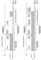
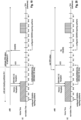
- Fig. 9 and 10 illustrate the DRX operation of a mobile station and a base station for the transmission or non-transmission of CSI/SRS depending on the result of the estimation as will be explained.
- the UE is in Active Time
- the DRX Inactivity Timer is running and would expire in subframe N-2, provided no PDDCH is received before.
- a PDCCH (be it an uplink grant or a downlink assignment) is received in subframe N-3, and subframes N-10 and N are configured for periodic CSI/SRS transmission.
- the UE reports CSI/SRS in subframe N-10 (not considered for explanation) and now needs to decide whether to report CSI/SRS in subframe N or not.
- the UE as well as the eNodeB now determine whether or not the UE shall transmit CSI/SRS as configured in subframe N or not. Correspondingly, the determination is based on whether subframe N is determined to be Active or Non-Active for the UE. Put differently, information relating to the DRX status of a subframe, available until and including subframe N-4 is considered for the determination, while information available after subframe N-4 is discarded for the determination (but still processed accordingly for other processes).
- the PDCCH is received in subframe N-3, i.e. after subframe N-4, and thus discarded for the determination as to whether or not the UE shall transmit CSI/SRS in subframe N.
- the PDCCH of subframe N-3 is considered as such for restarting the DRX-Inactivity Timer according to usual UE behavior, which thus leads to the case that the UE remains in Active Time.
- the UE and the eNodeB determine that the UE would be in Non-Active Time in subframe N (in contrast to the actual situation), for the following reason: until and including subframe N-4 no PDCCH was received to restart the DRX Inactivity Timer; thus, the UE and eNodeB determine, based on the current value of the DRX Inactivity Timer at subframe N-4, that the DRX Inactivity Timer will indeed expire in subframe N-2.
- the UE and the eNodeB determine that the UE will be in Non-Active Time in subframe N (which is not true, due to the not considered PDCCH in subframe N-3), and the UE will thus not transmit CSI/SRS contrary to the configuration (see Fig. 9 , "No UL transmission").
- the eNodeB will not expect any transmission of CSI/SRS from the UE and thus will not even try to receive CSI/SRS.
- Fig. 10 The exemplary scenario of Fig. 10 is quite similar to the one presented in Fig. 9 , with the important exception that the PDCCH is received in subframe N-4 instead of in subframe N-3. Consequently, the determination as to whether to transmit or not the CSI/SRS at the configured subframe N, in this case also considers the PDCCH at subframe N-4.
- the DRX-Inactivity Timer is restarted in subframe N-4, due to the received PDCCH.
- the estimation process estimates the DRX status of the UE for subframe N to be Active Time (assuming that DRX-Inactivity Timer will not have expired at subframe N), which means that the UE shall report CSI/SRS as configured.
- the eNodeB reaches the same conclusion based on the same information, and thus expects the CSI/SRS reporting from the UE. No double decoding at the eNodeB is necessary anymore, since the eNB and UE reach the same unambiguous estimation result.
- Fig. 11 a different DRX scenario is presented, based on which the above-described first aspect will be explained further. It is assumed that the UE is in DRX mode, in particular in the Short-DRX cycle, where OnDuration periods (Active Time) are alternated with DRX Opportunities (Non-Active Periods).
- OnDuration is taken as three subframes long, with the Short-DRX cycle being 7 subframes long; the Non-Active Time is thus 4 subframes.
- subframes N-10 and N are considered to be configured for periodic CSI/SRS reporting.
- the OnDuration Timer is running at the mobile station.
- the UE and the eNB can estimate at subframe N-4, considering grants/assignments received until and including subframe N-4, that the UE will be in Active Time in subframe N, i.e. OnDuration timer is running.
- OnDuration timer is running.
- the UE as well as the eNB can exactly estimate when the UE will be in Active Time and Non-Active Time.
- the UE and the eNodeB consider UL grants/DL assignments received up to and including subframe N-4 only, which in this case however means that no PDCCHs are considered since no PDCCHs are received recently.
- This in first instance means that the UE still remains in DRX mode, alternating Active Times with Non-Active Times.
- the UE/eNodeB would estimate that the UE is in Non-Active Time in subframe N, since no PDCCH was received in time (up to and including subframe N-4) to "wake up" the UE.
- the DRX-related timers at the subframe N-4 in particular the value of the Short-DRX cycle timer and the OnDuration timer
- the UE will be in Active Time in subframe N and thus shall report the CSI/SRS.
- Both the UE and the eNodeB come to the same determination result, and thus the UE transmits the CSI report and the SRS, and the eNodeB expects the CSI/SRS without the need of double decoding.
- the UE is thus in Active Time in subframe N (assuming DRX-Inactivity Timer does not expire before subframe N) and should report the CSI/SRS as configured.
- This case is one example where the DRX reporting would fall into the transient phase after the reception of a PDCCH, where the eNodeB needs to perform double decoding to determine whether CSI/SRS is actually transmitted or not.
- the present aspect however, it is possible to arrive at a foreseeable behavior of the UE which avoids the need of double decoding at the eNodeB.
- only UL grant and DL assignments are considered that are received until and including subframe N-4 for determining whether or not to transmit the periodic CSI/SRS as configured.
- the PDCCH is received at subframe N-2 and accordingly discarded for the estimation, which in combination with the DRX-related timer values/status leads to the estimation result that the UE is in Non-Active Time in subframe N, and thus the UE shall not transmit CSI/SRS to the eNodeB.
- the UE does not transmit CSI/SRS although it is in Active Time at subframe N, due to the received PDCCH in subframe N-2.
- the present aspect allows considering any or any combination of the DRX-related timers, also depending on which DRX timers are currently running, such as the DRX-retransmission timer or the Long-DRX cycle timer.
- the present aspect shall not be restricted to merely the above-explained exemplary scenarios.
- OnDuration timer is appealing for the determination whether to send CSI/SRS or not.
- the mobile can know beforehand when OnDuration timer is running based on the formula given in section 5.7 of TS36.321.
- the subframes where OnDuration timer is running can be unambiguously determined by the mobile station and the eNodeB for the different DRX cycles.
- whether DRX Short Cycle or DRX Long Cycle is used in a specific subframe depends on other factors like DRX-Inactivity timer status and correspondingly PDCCH reception status.
- UE will consider the grants/assignments received until and including subframe N-4 in order to determine whether OnDuration timer is running in subframe N, or in other words, UE will consider assignments/grants received until and including subframe N-4 only, in order to determine whether in subframe N DRX Short cycle or DRX Long Cycle is used and consequently whether OnDuration timer is running or not.
- the DRX-retransmission timer can be considered for the determination whether to send CSI/SRS info at a specific subframe. Since UE starts DRX-retransmission timer for the case that a transport block or PDSCH could not be decoded correctly in order to monitor PDCCH for further retransmissions of the transport block, UE knows already some subframes in advance whether DRX retransmission timer will be running in a specific subframe.
- UE when UE should determine whether to transmit periodic CSI/SRS at subframe N, UE knows already at subframe N-4 whether DRX-retransmission timer will be running at subframe N since HARQ feedback for a potential PDSCH transmission which might trigger the starting of DRX retransmission timer at subframe N would have been sent in subframe N-4. For example in case a PDSCH transmission was scheduled in subframe N-8 by a PDCCH which could't be correctly decoded, UE will sent a NACK at subframe N-4. Hence, the UE and also eNB know that UE will start the DRX retransmission timer at subframe N in order to monitor for potential retransmissions.
- the above aspect has been explained and illustrated in the figures as if no processing time would be necessary for the UE and the eNodeB to e.g. perform the estimation of whether or not to transmit the CSI/SRS at subframe N or process incoming PDCCHs.
- the above aspect was explained as if the processing took place "at subframe N-4".
- the UE and eNodeB will need more time to decode the PDCCH, process the transport block of the PDCCH, estimate the DRX-status of subframe N and of course also for preparing the CSI/SRS.
- the processing may start at subframe N-4 and may well last for another one or two subframes. The more important part is that although the estimation may actually take place in e.g.
- subframe N-3 (e.g. due to processing delay), only information (e.g. PDCCHs, DRX-timer values/status) until and including subframe N-4 are considered. Therefore, the time between subframe N-4 and subframe N may be considered as a time budget for the UE, to be used for amongst other: the decoding of the PDCCH, the processing of the transport block of the PDSCH, the estimation according to the aspect, the preparation of the CSI/SRS (if transmission is to be done). This applies in a similar manner to the remaining aspects, explained below.
- the processing according to the first aspect may only need to be performed four subframes before the subframe being configured for CSI and/or SRS; i.e. at subframe N-4 for configured subframe N
- the UE and/or eNodeB may also perform the estimation at every subframe N, independently from whether or not periodic CSI and/or periodic SRS are even configured for subframe N+4. Although this may lead to significant more processing, the complexity of the UE and eNodeB can be reduced.
- the second aspect deals with the problem that some unpredictable UE behavior remains for the case of DRX MAC control elements being received by the UE from the eNodeB, instructing the UE to enter DRX, i.e. to go into DRX mode and thus become Non-Active.
- the eNodeB does not know which transmission format will be used by the UE in subframe N, depending on whether or not CSI/SRS is transmitted (e.g. Format 1a vs Format 2a, see table for PUCCH format in background section).
- CSI/SRS e.g. Format 1a vs Format 2a
- subframes N-10 and N are configured for periodic CSI/SRS transmission.
- a PDCCH with a downlink resource assignment for a DRX MAC CE in the PDSCH is received in subframe N-4, as well as the DRX MAC CE via the PDSCH.
- the DRX MAC CE is an instruction from the eNodeB for the UE to enter DRX mode, i.e. to start e.g. the DRX-Short cycle (not depicted).
- HARQ is applied to the PDSCH containing the DRX MAC CE, for which reason the UE shall transmit a HARQ feedback (ACK/NACK) to the eNodeB at subframe N.
- ACK/NACK HARQ feedback
- the eNodeB does not know whether the UE received the DRX MAC CE sent in subframe N-4 correctly, without decoding the HARQ feedback (ACK/NACK) at subframe N.
- the estimation of the DRX status for the UE at subframe N depends on whether the UE received the MAC CE correctly or not.
- the UE goes into Non-Active Time as of subframe N-3 (ideally) and thus transmits an ACK without reporting CSI and transmitting SRS in subframe N (see Fig. 13 ).
- the UE fails to decode the DRX MAC CE correctly, thus stays in Active Time and transmits a NACK and CSI/SRS in subframe N (see Fig. 14 ).
- the eNodeB still needs to implement double decoding to cover for the above-described cases, which increases complexity of the eNodeB.
- a corresponding re-transmission of the DRX MAC CE is performed at the earliest 8 subframes after the initial transmission (according to configuration), and in the exemplary configuration of Fig. 14 is assumed to be 9 subframes after initial transmission in subframe N+5. It is assumed that the DRX MAC CE this time is decoded correctly, and thus the UE goes into DRX, Non-Active Time.
- the estimation as to whether or not to transmit the periodic CSI/SRS as configured considers only DRX MAC CEs received until and including subframe N-(4+k), where k is an integer of 1 to K, and subframe N is the subframe configured for periodic CSI and/or SRS. This ensures that the eNodeB knows in subframe N already whether the DRX MAC was correctly received by the UE or not. It may thus already know the transmission format used in subframe N.
- a transmission of the periodic CSI and/or SRS is controlled such that in case it is estimated that the UE will be in Active Time in subframe N, CSI/SRS is transmitted, and in case it is estimated that the UE will be in Non-Active Time in subframe N, CSI/SRS is not transmitted.
- CSI/SRS is transmitted, and in case it is estimated that the UE will be in Non-Active Time in subframe N, CSI/SRS is not transmitted.
- DRX MAC CE received in subframe N-4 is not considered for the estimation process, for which reason CSI/SRS is transmitted in subframe N together with the HARQ feedback (in the example of Fig. 15 , an ACK).
- the eNodeB performing the same determination and reaching the same result, expects the transmission of the CSI/SRS and a HARQ feedback for the DRX MAC CE. No double decoding is necessary. (ACK/NACK can be decoded without double decoding).
- the exemplary scenario of Fig. 16 assumes that the DRX MAC CE (and the corresponding PDCCH) is received in subframe N-5, instead of subframe N-4. It is further assumed that the DRX MAC CE was correctly decoded by the UE, which thus exits the Active Time and enters DRX Non-Active Time as of subframe N-4.
- an ACK is transmitted from the UE to the eNodeB four subframes after the DRX MAC CE, i.e. in subframe N-1.
- the eNodeB receives the HARQ feedback (e.g. ACK) and can deduce whether the DRX MAC CE was decoded correctly and applied by the UE.
- the HARQ feedback e.g. ACK
- the UE estimates that it will be in Non-Active Time in subframe N based on the correct reception of the DRX MAC CE, and thus does not transmit the periodic CSI/SRS.
- the eNodeB receiving the ACK, as HARQ feedback, also determines that the UE will be in Non-Active Time in subframe and thus does not expect any reception of the CSI/SRS.
- k may take other values too, such as 2, 3, 4 etc.
- Using a higher k value increases the internal processing time available to the eNB for processing the received HARQ feedback for a MAC CE and for deciding the expected PUCCH format to properly detect and decode the PUCCH in subframe N.
- the UE estimates the DRX status of itself for subframe N, and thus also whether or not to transmit the periodic CSI/SRS in subframe N based on:
- the UE may estimate the DRX status of itself in subframe N, and thus also whether or not to transmit the periodic CSI/SRS in subframe N based on:
- the processing according to the second aspect may only need to be performed five (or N-(4+k)) subframes before the subframe being configured for CSI and/or SRS.
- the UE and/or eNodeB may also perform the estimation at every subframe N, independently from whether or not periodic CSI and/or periodic SRS are even configured for subframe N+(4+k). Although this may lead to significant more processing, the complexity of the UE and eNodeB can be reduced.
- DRX MAC control elements that are received until and including subframe N-(4+k) are considered for the estimation as well as UL grants/DL assignments received until and including subframe N-4; in a further alternative variant DRX-related timers may be additionally considered for the estimation to improve the estimation.
- DRX-related timers may be additionally considered for the estimation to improve the estimation.
- the present third aspect is closely related to any of the variants of the second aspect, albeit changing the valid time periods of the information considered for the estimation.
- the UE and the eNodeB determine whether or not the UE is in Active Time for subframe N and thus whether it shall transmit periodic CSI/SRS as configured at subframe N based on UL grants / DL assignments received by the UE until and including subframe N-(4+k) where k is a positive integer value of 1 to K.
- DRX MAC CEs received by the UE until and including subframe N-(4+k) are also considered for the determination.
- the status of the DRX-related timers e.g.
- DRX OnDuration timer and DRX-retransmission timer for subframe N estimated at subframe N-(4+k), i.e. considering grants/assignments received until and including subframe N-(4+k), are to be considered, rather than at subframe N-4 as before.
- the fourth aspect deals also with the problem caused by the reception of DRX MAC control elements, as already explained for the second aspect (see above).
- DRX MAC CEs received by the UE until and including subframe N-(4+k) according to the second aspect
- only DRX MAC CEs are considered for the estimation for which an Acknowledgement (HARQ feedback) has been sent from the UE to the eNodeB until and including subframe N-(3+k); k is a positive integer from 1 to K.
- HARQ feedback Acknowledgement
- k is a positive integer from 1 to K.
- the advantage is that both the eNodeB and the UE have the same understanding of what information is taken into account for determining whether to send or not periodic CSI/SRS in subframe N.
- the fourth aspect will be explained in connection with Fig. 17 to 19 .
- the PDCCH, indicating the transmission for the DRX MAC CE on PDSCH, and the DRX MAC CE are received in subframe N-8.
- the UE determines whether or not to transmit the periodic CSI/SRS as configured for subframe N, based on the Acknowledgment for the DRX MAC CE sent at subframe N-4.
- the DRX MAC CE is acknowledged in subframe N-4, i.e. ACK is sent to the eNodeB, and thus the UE determines that it will not transmit the CSI/SRS as configured in subframe N, since it will be in Non-Active Time in subframe N.
- the eNodeB expects and receives the HARQ feedback ACK in subframe N-4, and thus determines that the UE will not transmit the periodic CSI/SRS in subframe N. No double decoding is necessary.
- Fig. 18 is similar to the exemplary scenario in Fig. 17 , with the difference that it is assumed that the DRX MAC CE was not successfully decoded by the UE, which thus transmits a NACK HARQ feedback to the eNodeB in subframe N-4, and stays Active accordingly. Since no Acknowledgement was sent for the DRX MAC CE until and including subframe N-4, but rather a NACK, the UE determines that it will send periodic CSI/SRS in subframe N. The eNodeB reaches the same conclusion, since it receives the NACK of subframe N-4 and thus learns that the UE could not decode and properly apply the DRX MAC CE.
- the eNodeB after receiving the NACK for the DRX MAC CE from the UE, retransmits the DRX MAC CE 9 subframes after the initial transmission. After the retransmission, the UE is assumed to be able to decode the DRX MAC CE correctly and to thus enter DRX mode, in particular Non-Active Time. A corresponding HARQ feedback ACK for the retransmitted DRX MAC CE is transmitted in subframe N+5.
- Fig. 19 illustrates an exemplary scenario, similar to the one of Fig. 17 and 18 , but with the significant difference that the DRX MAC CE is received in subframe N-7, not subframe N-8.
- the HARQ feedback for the reception of the DRX MAC CE is transmitted from the UE to the eNodeB four subframes after the reception, i.e. at subframe N-3, and thus outside of the window defined for being considered for the determination of whether or not to transmit the periodic CSI/SRS in subframe N. Therefore, the DRX MAC CE received by the UE in subframe N-7 is discarded for the determination, although it is of course properly processed by other functions of the UE.
- the UE in case the UE is able to successfully process the DRX MAC CE it will enter DRX, i.e. become Non-Active, but still has to transmit CSI/SRS in subframe N, although it would not be in Active Time at subframe N according to DRX.
- a further fifth aspect considerably differs from the previous aspects, and mainly avoids the ambiguousness of the CSI/SRS transmission from the UE in the transient phases, by considering a DRX status of a previous subframe N-k for the determination of whether or not to transmit the periodic CSI/SRS in subframe N.
- the UE shall transmit the periodic CSI and/or SRS to the eNodeB as configured for subframe N, in case the UE is in Active Time in subframe N-k, where k is a positive integer from 1 to K.
- This fifth aspect provides a simple behavior for the UE and eNodeB, but still ensuring predictability of the CSI/SRS transmission to avoid the double decoding at the eNodeB.
- the UE takes the DRX status (i.e. Active Time or Non-Active Time) in subframe N-4 and assumes for the determination same to be the DRX status of subframe N.
- the UE can thus determine whether or not to transmit the periodic CSI/SRS in subframe N based on the DRX status of subframe N-4.
- Fig. 20 illustrates the exemplary scenario of Fig. 19 , but with the fifth aspect applied, instead of applying the fourth aspect. Accordingly, it is assumed that a PDCCH and the DRX MAC CE indicated by the PDCCH, are received in subframe N-7, that the UE correctly decodes the DRX MAC CE and thus (ideally) enters the DRX Non-Active time as of subframe N-6. An Ack is transmitted as the HARQ feedback for the DRX MAC CE in subframe N-3 to the eNodeB.
- the UE determines whether it is in Active Time in subframe N-4 or not. Since the UE is not in Active Time in subframe N-4, due to the correctly decoded DRX MAC CE received previously, the UE will determine not to transmit the CSI/SRS.
- the eNodeB makes the similar determination and comes to the result that the UE will not transmit the CSI/SRS since the UE is in Non-Active Time in subframe N-4, which is the relevant DRX status for transmitting CSI/SRS in subframe N.
- the UE when the DRX MAC CE is not correctly decoded by the UE, which thus does not enter Non-Active time as of subframe N-6 but remains Active, the UE will be in Active time in subframe N-4, and thus CSI/SRS will be reported at subframe N as configured.
- eNodeB comes to the same determination result, and thus expects and receives the periodic CSI/SRS in subframe N.
- This fifth aspect reduces the complexity of the implementation for both the UE and eNodeB, while solving the problem of avoiding double decoding at the eNodeB.
- the CSI/SRS reporting period is basically shifted by k subframes compared to the DRX Active Time, i.e. CSI/SRS reporting starts k subframes after DRX Active Time is started, and ends k subframes after DRX Active Time ends.
- each of said aspects provides a user equipment (mobile terminal) and a eNodeB (base station).
- the user equipment is adapted to perform the methods described herein.
- a computing device or processor may for example be general purpose processors, digital signal processors (DSP), application specific integrated circuits (ASIC), field programmable gate arrays (FPGA) or other programmable logic devices, etc.
- DSP digital signal processors
- ASIC application specific integrated circuits
- FPGA field programmable gate arrays
- the various aspects of the invention may also be performed or embodied by a combination of these devices.
- the various aspects may also be implemented by means of software modules, which are executed by a processor or directly in hardware. Also a combination of software modules and a hardware implementation may be possible.
- the software modules may be stored on any kind of computer readable storage media, for example RAM, EPROM, EEPROM, flash memory, registers, hard disks, CD-ROM, DVD, etc.
Claims (15)
- Station mobile comprenant :un récepteur adapté pour recevoir, d'une station de base, une information de configuration pour la transmission, dans la sous-trame N d'une liaison montante vers la station de base, d'au moins un rapport d'information sur la qualité du canal et d'un symbole de référence de sondage, et pour recevoir de la station de base un élément de contrôle d'accès au support (MAC) concernant une opération de réception discontinue (DRX),des circuits adaptés pour déterminer si la station mobile sera en période active DRX ou en période non active DRX dans la sous-trame N, sur la base au moins de l'élément de contrôle MAC reçu jusqu'à la sous-trame N-(4+k) incluse, où k est une valeur entière égale ou supérieure à 1, etun émetteur adapté pour ne pas transmettre le rapport d'information sur la qualité du canal ou le symbole de référence de sondage à la station de base dans la sous-trame N, s'il est déterminé que la station mobile n'est pas en période active DRX dans la sous-trame N.
- Station mobile selon la revendication 1, qui est configurée pour transmettre périodiquement au moins l'un du rapport d'information sur la qualité du canal et du symbole de référence de sondage.
- Station mobile selon la revendication 1 ou 2, dans laquelle le circuit est adapté pour déterminer si la station mobile sera en période active DRX ou en période non active DRX dans la sous-trame N, sur la base d'au moins une des concessions de ressources sur la liaison montante pour un canal partagé sur la liaison montante et des allocations de ressources sur la liaison descendante pour un canal partagé sur la liaison descendante, qui sont reçues par la station mobile jusqu'à la sous-trame N-(4+k) incluse.
- Station mobile selon l'une des revendications 1 à 3, dans laquelle l'émetteur est adapté pour transmettre au moins l'un du rapport d'information sur la qualité du canal et du symbole de référence de sondage à la station de base dans la sous-trame N, dans le cas où la station mobile est déterminée comme étant en période active DRX dans la sous-trame N.
- Station mobile selon l'une des revendications 1 à 4, dans laquelle le circuit est adapté pour déterminer si la station mobile sera en période active DRX ou en période non active DRX dans la sous-trame N, sur la base des horloges liées à DRX en cours d'exécution pour la station mobile, y compris au moins une horloge d'inactivité DRX, une horloge de durée d'activation DRX et une horloge de retransmission DRX.
- Station mobile selon l'une des revendications 1 à 5, dans laquelle l'émetteur est configuré, par la signalisation de contrôle des ressources radio (RRC), pour limiter la transmission périodique des rapports d'information sur la qualité du canal à la seule période d'activité DRX.
- Station mobile selon l'une des revendications 1 à 6, dans laquelle le circuit est adapté pour déterminer de ne pas tenir compte de tout élément de contrôle MAC concernant une opération DRX dans les sous-trames N-(3+k) à N.
- Station mobile selon l'une des revendications 1 à 7, dans laquelle la valeur entière de k est égale à 1.
- Procédé exécuté par une station mobile comprenant :la réception, d'une station de base, d'information de configuration pour la transmission, dans la sous-trame N d'une liaison montante vers la station de base, d'au moins un rapport d'information sur la qualité du canal et d'un symbole de référence de sondage,la réception, de la station de base, d'un élément de contrôle de contrôle d'accès au support (MAC) concernant une opération de réception discontinue (DRX),la détermination du fait que la station mobile sera en période active DRX ou en période non active DRX dans la sous-trame N, sur la base au moins de l'élément de contrôle MAC reçu jusqu'à la sous-trame N-(4+k) incluse, où k est une valeur entière égale ou supérieure à 1, etla détermination du fait de ne pas transmettre le rapport d'information sur la qualité du canal ou le symbole de référence de sondage à la station de base dans la sous-trame N, s'il est déterminé que la station mobile n'est pas en période active DRX dans la sous-trame N.
- Procédé selon la revendication 9, comprenant :
la transmission périodiquement d'au moins l'un du rapport d'information sur la qualité du canal et du symbole de référence de sondage. - Procédé selon la revendication 9 ou 10, dans lequel l'étape consistant à déterminer si la station mobile sera en période active DRX ou en période non active DRX dans la sous-trame N, est basée sur au moins l'une des concessions de ressources en liaison montante pour un canal partagé en liaison montante et des allocations de ressources en liaison descendante pour un canal partagé en liaison descendante, qui sont reçues par la station mobile jusqu'à la sous-trame N-(4+k) incluse.
- Procédé selon l'une des revendications 9 à 11, comprenant :
la transmission d'au moins l'un du rapport d'information sur la qualité du canal et du symbole de référence de sondage à la station de base dans la sous-trame N, s'il est déterminé que la station mobile n'est pas en période active DRX dans la sous-trame N. - Procédé selon l'une des revendications 9 à 12, dans lequel l'étape de détermination est basée sur les horloges liées à DRX en cours d'exécution pour la station mobile, y compris au moins une horloge d'inactivité DRX, une horloge de durée d'activation DRX et une horloge de retransmission DRX.
- Procédé selon l'une des revendications 9 à 13, comprenant :
en réponse à la signalisation de contrôle des ressources radio (RRC), limiter la transmission périodique des rapports d'information sur la qualité du canal à la seule période d'activité DRX. - Procédé selon l'une des revendications 9 à 14, comprenant :la détermination du fait de ne pas tenir compte de tout élément de contrôle MAC concernant une opération DRX dans les sous-trames N-(3+k) à N, et/ouoù la valeur entière de k est égale à 1.
Priority Applications (1)
| Application Number | Priority Date | Filing Date | Title |
|---|---|---|---|
| EP23192198.2A EP4254852A3 (fr) | 2013-03-20 | 2013-12-04 | Comportement d'ue déterministe pour rapport csi/srs pendant une drx |
Applications Claiming Priority (6)
| Application Number | Priority Date | Filing Date | Title |
|---|---|---|---|
| EP13160199.9A EP2782409A1 (fr) | 2013-03-20 | 2013-03-20 | Comportement d'UE déterministe pour rapport CSI/SRS en DRX |
| EP17153572.7A EP3179808B1 (fr) | 2013-03-20 | 2013-12-04 | Comportement d'ue déterministe pour rapport csi/srs pendant drx |
| EP13801555.7A EP2976923B1 (fr) | 2013-03-20 | 2013-12-04 | Comportement d'ue déterministe pour rapport csi/srs en drx |
| EP19212244.8A EP3634064B1 (fr) | 2013-03-20 | 2013-12-04 | Comportement d'ue déterministe pour rapport csi/srs pendant drx |
| PCT/EP2013/075499 WO2014146736A1 (fr) | 2013-03-20 | 2013-12-04 | Comportement d'ue déterministe pour la déclaration csi/srs pendant le drx |
| EP18180846.0A EP3416443B1 (fr) | 2013-03-20 | 2013-12-04 | Comportement d'ue déterministe pour rapport csi/srs pendant drx |
Related Parent Applications (5)
| Application Number | Title | Priority Date | Filing Date |
|---|---|---|---|
| EP13801555.7A Division EP2976923B1 (fr) | 2013-03-20 | 2013-12-04 | Comportement d'ue déterministe pour rapport csi/srs en drx |
| EP18180846.0A Division EP3416443B1 (fr) | 2013-03-20 | 2013-12-04 | Comportement d'ue déterministe pour rapport csi/srs pendant drx |
| EP17153572.7A Division EP3179808B1 (fr) | 2013-03-20 | 2013-12-04 | Comportement d'ue déterministe pour rapport csi/srs pendant drx |
| EP19212244.8A Division-Into EP3634064B1 (fr) | 2013-03-20 | 2013-12-04 | Comportement d'ue déterministe pour rapport csi/srs pendant drx |
| EP19212244.8A Division EP3634064B1 (fr) | 2013-03-20 | 2013-12-04 | Comportement d'ue déterministe pour rapport csi/srs pendant drx |
Related Child Applications (2)
| Application Number | Title | Priority Date | Filing Date |
|---|---|---|---|
| EP23192198.2A Division EP4254852A3 (fr) | 2013-03-20 | 2013-12-04 | Comportement d'ue déterministe pour rapport csi/srs pendant une drx |
| EP23192198.2A Division-Into EP4254852A3 (fr) | 2013-03-20 | 2013-12-04 | Comportement d'ue déterministe pour rapport csi/srs pendant une drx |
Publications (3)
| Publication Number | Publication Date |
|---|---|
| EP3852468A1 EP3852468A1 (fr) | 2021-07-21 |
| EP3852468B1 true EP3852468B1 (fr) | 2023-11-01 |
| EP3852468C0 EP3852468C0 (fr) | 2023-11-01 |
Family
ID=47915502
Family Applications (7)
| Application Number | Title | Priority Date | Filing Date |
|---|---|---|---|
| EP13160199.9A Withdrawn EP2782409A1 (fr) | 2013-03-20 | 2013-03-20 | Comportement d'UE déterministe pour rapport CSI/SRS en DRX |
| EP21160396.4A Active EP3852468B1 (fr) | 2013-03-20 | 2013-12-04 | Comportement d'ue déterministe pour rapport csi/srs pendant drx |
| EP19212244.8A Active EP3634064B1 (fr) | 2013-03-20 | 2013-12-04 | Comportement d'ue déterministe pour rapport csi/srs pendant drx |
| EP17153572.7A Active EP3179808B1 (fr) | 2013-03-20 | 2013-12-04 | Comportement d'ue déterministe pour rapport csi/srs pendant drx |
| EP23192198.2A Pending EP4254852A3 (fr) | 2013-03-20 | 2013-12-04 | Comportement d'ue déterministe pour rapport csi/srs pendant une drx |
| EP18180846.0A Active EP3416443B1 (fr) | 2013-03-20 | 2013-12-04 | Comportement d'ue déterministe pour rapport csi/srs pendant drx |
| EP13801555.7A Active EP2976923B1 (fr) | 2013-03-20 | 2013-12-04 | Comportement d'ue déterministe pour rapport csi/srs en drx |
Family Applications Before (1)
| Application Number | Title | Priority Date | Filing Date |
|---|---|---|---|
| EP13160199.9A Withdrawn EP2782409A1 (fr) | 2013-03-20 | 2013-03-20 | Comportement d'UE déterministe pour rapport CSI/SRS en DRX |
Family Applications After (5)
| Application Number | Title | Priority Date | Filing Date |
|---|---|---|---|
| EP19212244.8A Active EP3634064B1 (fr) | 2013-03-20 | 2013-12-04 | Comportement d'ue déterministe pour rapport csi/srs pendant drx |
| EP17153572.7A Active EP3179808B1 (fr) | 2013-03-20 | 2013-12-04 | Comportement d'ue déterministe pour rapport csi/srs pendant drx |
| EP23192198.2A Pending EP4254852A3 (fr) | 2013-03-20 | 2013-12-04 | Comportement d'ue déterministe pour rapport csi/srs pendant une drx |
| EP18180846.0A Active EP3416443B1 (fr) | 2013-03-20 | 2013-12-04 | Comportement d'ue déterministe pour rapport csi/srs pendant drx |
| EP13801555.7A Active EP2976923B1 (fr) | 2013-03-20 | 2013-12-04 | Comportement d'ue déterministe pour rapport csi/srs en drx |
Country Status (18)
| Country | Link |
|---|---|
| US (9) | US9686067B2 (fr) |
| EP (7) | EP2782409A1 (fr) |
| JP (3) | JP6685032B2 (fr) |
| KR (2) | KR102166750B1 (fr) |
| CN (2) | CN105165085B (fr) |
| BR (1) | BR112015023339B1 (fr) |
| CA (1) | CA2904392C (fr) |
| DK (1) | DK3179808T3 (fr) |
| ES (2) | ES2694673T3 (fr) |
| HU (1) | HUE041847T2 (fr) |
| MY (1) | MY174678A (fr) |
| PL (1) | PL3179808T3 (fr) |
| PT (1) | PT3179808T (fr) |
| RU (2) | RU2739584C2 (fr) |
| TR (1) | TR201815664T4 (fr) |
| TW (1) | TWI643473B (fr) |
| WO (1) | WO2014146736A1 (fr) |
| ZA (1) | ZA201506898B (fr) |
Families Citing this family (107)
| Publication number | Priority date | Publication date | Assignee | Title |
|---|---|---|---|---|
| EP2782409A1 (fr) * | 2013-03-20 | 2014-09-24 | Panasonic Intellectual Property Corporation of America | Comportement d'UE déterministe pour rapport CSI/SRS en DRX |
| CN104753627A (zh) * | 2013-12-26 | 2015-07-01 | 中兴通讯股份有限公司 | 多路径传输方法、系统及数据发送装置和数据接收装置 |
| WO2015137719A1 (fr) * | 2014-03-12 | 2015-09-17 | 엘지전자 주식회사 | Procédé permettant de recevoir un canal de communication en liaison descendante dans un système de communication sans fil appliquant la technique d'agrégation de porteuses, et appareil associé |
| CN106165519B (zh) * | 2014-05-08 | 2020-04-21 | 华为技术有限公司 | 一种数据调度方法及装置 |
| US9930626B2 (en) * | 2014-05-09 | 2018-03-27 | Futurewei Technologies, Inc. | Device, network, and method for communications with dynamic adaptation |
| US10187186B2 (en) | 2014-09-30 | 2019-01-22 | Qualcomm Incorporated | Uplink grant management for LTE in unlicensed spectrum |
| CN105723752B (zh) * | 2014-10-20 | 2019-12-06 | 华为技术有限公司 | 信息传输方法、设备和系统 |
| CN110035439B (zh) * | 2014-10-23 | 2023-02-28 | 上海朗帛通信技术有限公司 | 一种蜂窝网中的laa传输方法和装置 |
| US10856357B2 (en) * | 2014-11-13 | 2020-12-01 | Telefonaktiebolaget Lm Ericsson (Publ) | Systems and methods of discontinuous operation for wireless devices |
| WO2016093745A1 (fr) * | 2014-12-08 | 2016-06-16 | Telefonaktiebolaget Lm Ericsson (Publ) | Procédé et nœud de réseau radio pour estimer la qualité d'un canal |
| US9924525B2 (en) * | 2015-02-25 | 2018-03-20 | Qualcomm Incorporated | Channel feedback preceding downlink data transmissions in cellular IoT systems |
| US10555367B2 (en) * | 2015-02-27 | 2020-02-04 | Kyocera Corporation | Radio terminal |
| US10355828B2 (en) * | 2015-03-02 | 2019-07-16 | Qualcomm Incorporated | Fast radio link control error recovery with low latency transmissions |
| US9936519B2 (en) | 2015-03-15 | 2018-04-03 | Qualcomm Incorporated | Self-contained time division duplex (TDD) subframe structure for wireless communications |
| US10075970B2 (en) | 2015-03-15 | 2018-09-11 | Qualcomm Incorporated | Mission critical data support in self-contained time division duplex (TDD) subframe structure |
| US9980204B2 (en) | 2015-03-16 | 2018-05-22 | Ofinno Technologies, Llc | Channel state information transmission |
| US9954668B2 (en) | 2015-03-23 | 2018-04-24 | Qualcomm Incorporated | Co-existence system synchronization on a shared communication medium |
| US9877334B2 (en) | 2015-04-05 | 2018-01-23 | Ofinno Technologies, Llc | Cell configuration in a wireless device and wireless network |
| US11641255B2 (en) | 2015-04-05 | 2023-05-02 | Comcast Cable Communications, Llc | Uplink control information transmission in a wireless network |
| WO2016164058A1 (fr) * | 2015-04-08 | 2016-10-13 | Ntt Docomo, Inc. | Station de base, équipement utilisateur et procédé pour déterminer une matrice de pré-codage |
| US9814058B2 (en) | 2015-05-15 | 2017-11-07 | Qualcomm Incorporated | Scaled symbols for a self-contained time division duplex (TDD) subframe structure |
| JP6967450B2 (ja) * | 2015-06-19 | 2021-11-17 | シャープ株式会社 | 端末装置、通信方法、および、集積回路 |
| WO2017003047A1 (fr) | 2015-07-02 | 2017-01-05 | 엘지전자(주) | Procédé de transmission et de réception de données de liaison montante dans un système de communications sans fil, et dispositif associé |
| US9992790B2 (en) | 2015-07-20 | 2018-06-05 | Qualcomm Incorporated | Time division duplex (TDD) subframe structure supporting single and multiple interlace modes |
| DE102015009779B4 (de) * | 2015-07-27 | 2021-08-12 | Apple Inc. | Leistungsoptimierung für Kanalzustandsmeldungen in einem drahtlosen Kommunikationsnetz |
| JP6745870B2 (ja) | 2015-08-14 | 2020-08-26 | 華為技術有限公司Huawei Technologies Co.,Ltd. | アップリンク制御情報を送信するための方法および装置 |
| JP6646738B2 (ja) * | 2015-09-10 | 2020-02-14 | 華為技術有限公司Huawei Technologies Co.,Ltd. | データ伝送方法、端末及びranデバイス |
| EP3343973B1 (fr) * | 2015-09-25 | 2019-11-13 | Huawei Technologies Co., Ltd. | Procédé pour rapporter un résultat de mesure et appareil de mesure |
| WO2017067573A1 (fr) * | 2015-10-19 | 2017-04-27 | Huawei Technologies Co., Ltd. | Dispositif utilisateur, noeud de réseau, procédé et programme informatique associés |
| US11129185B2 (en) * | 2015-12-09 | 2021-09-21 | Qualcomm Incorporated | Macro and micro discontinuous transmission |
| EP3394991B1 (fr) * | 2015-12-23 | 2021-10-20 | Telefonaktiebolaget LM Ericsson (publ) | Procédé et appareil de commande de transmission de faisceau vers des équipements utilisateur groupés |
| CN106954270B (zh) * | 2016-01-06 | 2021-12-28 | 夏普株式会社 | 无线资源控制流程监测方法和设备 |
| EP3402109B1 (fr) * | 2016-01-08 | 2021-12-01 | LG Electronics Inc. | Procédé de récupération d'erreur et dispositif multicanal associé dans un système de communication sans fil |
| JP6682890B2 (ja) * | 2016-02-05 | 2020-04-15 | 富士通株式会社 | 基地局、無線端末、無線通信システム、基地局のスケジューリング方法および無線端末の通信方法 |
| US9967293B2 (en) * | 2016-02-10 | 2018-05-08 | Samsung Electronics Co., Ltd. | Framework for comprehensive monitoring and learning context of VoLTE call |
| WO2017164667A1 (fr) * | 2016-03-24 | 2017-09-28 | Lg Electronics Inc. | Procédé de configuration de réception discontinue dans un système de communication, et dispositif associé |
| EP3226456B1 (fr) * | 2016-04-01 | 2020-06-03 | Panasonic Intellectual Property Corporation of America | Protocole de retransmission asynchrone |
| WO2017176189A1 (fr) * | 2016-04-07 | 2017-10-12 | Telefonaktiebolaget Lm Ericsson (Publ) | Nœud de réseau radio, dispositif sans fil et procédés réalisés dans ceux-ci |
| WO2017177440A1 (fr) * | 2016-04-15 | 2017-10-19 | 富士通株式会社 | Appareil et procédé de transmission de l'indication d'état, et système de communication |
| WO2017204524A1 (fr) * | 2016-05-23 | 2017-11-30 | 엘지전자 주식회사 | Procédé et équipement utilisateur pour la réception d'informations de commande de liaison descendante |
| EP3497869B1 (fr) * | 2016-08-11 | 2020-09-09 | Fraunhofer Gesellschaft zur Förderung der Angewand | Appareils de communication de données, système de communication de données et procédés utilisant des symboles de référence |
| WO2018028620A1 (fr) * | 2016-08-12 | 2018-02-15 | 上海朗帛通信技术有限公司 | Procédé et dispositif de transmission sans fil |
| US10708938B2 (en) | 2016-10-31 | 2020-07-07 | Samsung Electronics Co., Ltd. | Transmission of UL control channels with dynamic structures |
| US10334533B2 (en) | 2016-11-02 | 2019-06-25 | At&T Intellectual Property I, L.P. | Non-orthogonal design for channel state information reference signals for a 5G air interface or other next generation network interfaces |
| US10362571B2 (en) * | 2016-11-04 | 2019-07-23 | Qualcomm Incorporated | Power control and triggering of sounding reference signal on multiple component carriers |
| US10779312B2 (en) * | 2016-11-11 | 2020-09-15 | Qualcomm Incorporated | Discontinuous reception and scheduling techniques in wireless communication systems using multiple transmission time intervals |
| EP3547761B1 (fr) * | 2016-12-01 | 2022-05-04 | Guangdong Oppo Mobile Telecommunications Corp., Ltd. | Procédé et dispositif pour réception discontinue |
| US10237032B2 (en) | 2017-01-06 | 2019-03-19 | At&T Intellectual Property I, L.P. | Adaptive channel state information reference signal configurations for a 5G wireless communication network or other next generation network |
| US10320512B2 (en) | 2017-01-08 | 2019-06-11 | At&T Intellectual Property I, L.P. | Interference cancelation for 5G or other next generation network |
| BR112019019679B1 (pt) * | 2017-03-23 | 2020-12-08 | Lg Electronics Inc | método e equipamento de usuário para receber sinais de enlace descendente |
| JP7091359B2 (ja) | 2017-03-23 | 2022-06-27 | フラウンホーファー-ゲゼルシャフト・ツール・フェルデルング・デル・アンゲヴァンテン・フォルシュング・アインゲトラーゲネル・フェライン | 移動通信ネットワークの無線アクセスネットワークのエンティティ間での信頼できるデータパケット送信 |
| WO2019014908A1 (fr) * | 2017-07-20 | 2019-01-24 | Zte Corporation | Configuration de porteuse de liaison montante |
| WO2019033017A1 (fr) * | 2017-08-10 | 2019-02-14 | Convida Wireless, Llc | Procédures de drx en mode connecté améliorées pour nr |
| US11395269B2 (en) | 2017-08-11 | 2022-07-19 | Telefonaktiebolaget Lm Ericsson (Publ) | Code rate for control information |
| CN111357388B (zh) * | 2017-09-15 | 2023-12-29 | 诺基亚技术有限公司 | 用于具有连接模式非连续接收的波束管理的基于时间的有效性 |
| US10524266B2 (en) | 2017-10-20 | 2019-12-31 | Google Llc | Switching transmission technologies within a spectrum based on network load |
| US10805979B2 (en) * | 2017-11-21 | 2020-10-13 | Qualcomm Incorporated | Dual band discontinuous reception |
| EP4191919A1 (fr) * | 2017-11-22 | 2023-06-07 | FG Innovation Company Limited | Opérations de réception discontinue parmi de multiples parties de bande passante |
| US11006413B2 (en) | 2017-12-06 | 2021-05-11 | Google Llc | Narrow-band communication |
| US10779303B2 (en) | 2017-12-12 | 2020-09-15 | Google Llc | Inter-radio access technology carrier aggregation |
| JP7027150B2 (ja) * | 2017-12-13 | 2022-03-01 | シャープ株式会社 | 端末装置、基地局装置、通信方法、および、集積回路 |
| US10608721B2 (en) | 2017-12-14 | 2020-03-31 | Google Llc | Opportunistic beamforming |
| US11246143B2 (en) * | 2017-12-15 | 2022-02-08 | Google Llc | Beamforming enhancement via strategic resource utilization |
| CN111480305B (zh) | 2017-12-15 | 2022-04-19 | 谷歌有限责任公司 | 基于卫星的窄带通信 |
| US10868654B2 (en) | 2017-12-15 | 2020-12-15 | Google Llc | Customizing transmission of a system information message |
| CN110011752B (zh) * | 2018-01-04 | 2021-10-22 | 维沃移动通信有限公司 | 一种cqi上报方法、终端设备及网络设备 |
| US10772151B2 (en) | 2018-01-05 | 2020-09-08 | Ofinno, Llc | Beam management in discontinuous reception |
| US10834777B2 (en) * | 2018-01-11 | 2020-11-10 | Ofinnon, LLC | Discontinuous reception and CSI |
| CN110099394B (zh) * | 2018-01-29 | 2022-07-29 | 展讯通信(上海)有限公司 | 异频测量及异系统测量的实现方法、装置及用户设备 |
| US11251847B2 (en) | 2018-03-28 | 2022-02-15 | Google Llc | User device beamforming |
| KR102450978B1 (ko) * | 2018-03-28 | 2022-10-05 | 삼성전자 주식회사 | 차세대 무선통신 시스템에서 비연속수신모드가 적용시 채널상태보고를 수행하는 방법 및 장치 |
| CN110351813B (zh) * | 2018-04-03 | 2020-10-27 | 维沃移动通信有限公司 | 一种信息上报方法、终端及网络设备 |
| WO2019191954A1 (fr) * | 2018-04-04 | 2019-10-10 | Oppo广东移动通信有限公司 | Procédé de transmission d'informations, et dispositif terminal |
| US11115150B2 (en) * | 2018-05-09 | 2021-09-07 | FG Innovation Company Limited | Methods and devices for reporting CSI during DRX operations |
| CN108738162B (zh) * | 2018-06-22 | 2020-12-08 | 广州红贝科技有限公司 | 一种无线物联网通信系统快速释放信道的方法 |
| CN112425254B (zh) * | 2018-07-16 | 2023-03-24 | 华为技术有限公司 | 用于低功耗的调度装置及方法 |
| CN112640327B (zh) | 2018-09-10 | 2024-04-09 | 谷歌有限责任公司 | 实现快速波束跟踪的方法、基站及用户设备 |
| US10660152B1 (en) * | 2018-09-13 | 2020-05-19 | Sprint Spectrum L.P. | Invoking DRX mode based on high-quality connection |
| KR102602381B1 (ko) | 2018-10-05 | 2023-11-16 | 삼성전자주식회사 | 무선 통신 시스템에서 무선 통신망을 이용한 동기화를 위한 장치 및 방법 |
| US11546103B2 (en) * | 2018-10-19 | 2023-01-03 | Qualcomm Incorporated | Physical layer aspects of round-trip time and observed time difference of arrival based positioning |
| WO2020122528A1 (fr) * | 2018-12-12 | 2020-06-18 | 엘지전자 주식회사 | Procédé de réalisation d'une surveillance de pdcch par un terminal dans un système de communication sans fil, et terminal faisant appel audit procédé |
| TWI690234B (zh) * | 2018-12-27 | 2020-04-01 | 財團法人工業技術研究院 | 調配通道狀態回報的基站與通道狀態回報調配方法 |
| US11146921B2 (en) | 2018-12-27 | 2021-10-12 | Industrial Technology Research Institute | Method of grouping user devices |
| TWI690225B (zh) * | 2018-12-27 | 2020-04-01 | 財團法人工業技術研究院 | 用戶設備的分群方法 |
| US10862656B2 (en) * | 2018-12-27 | 2020-12-08 | Industrial Technology Research Institute | Base station capable of allocating channel-state report and method for allocating channel-state report |
| CN111436126A (zh) * | 2019-01-11 | 2020-07-21 | 中兴通讯股份有限公司 | 一种信息的发送方法及装置、存储介质和电子装置 |
| CN111698106A (zh) * | 2019-03-12 | 2020-09-22 | 大唐移动通信设备有限公司 | 一种参数配置的方法和装置 |
| CN111917492B (zh) * | 2019-05-09 | 2023-03-28 | 中国移动通信有限公司研究院 | 一种校准方法、网络设备及终端设备 |
| US11284384B2 (en) | 2019-05-21 | 2022-03-22 | Commscope Technologies Llc | Dummy downlink transmission assignments for extension of on state of discontinuous reception (DRX) cycle |
| US11665566B2 (en) * | 2019-08-09 | 2023-05-30 | Qualcomm Incorporated | Event triggered reference signal transmission |
| US11405288B2 (en) * | 2019-08-22 | 2022-08-02 | Qualcomm Incorporated | Dynamic physical downlink control channel skipping indication |
| US11690132B2 (en) * | 2019-09-03 | 2023-06-27 | Qualcomm Incorporated | Medium access control-control element (MAC-CE) communication |
| US11553418B2 (en) | 2019-09-12 | 2023-01-10 | Lenovo (Singapore) Pte. Ltd. | Reporting transmission for discontinuous reception |
| EP4123915A1 (fr) * | 2019-10-03 | 2023-01-25 | Ofinno, LLC | Réception discontinue pour une procédure d'accès aléatoire en deux étapes |
| US11792671B2 (en) * | 2019-11-18 | 2023-10-17 | Qualcomm Incorporated | Channel state information reporting over discontinuous reception operations |
| CN112887066B (zh) * | 2019-11-29 | 2023-03-31 | 中国移动通信有限公司研究院 | Cdrx参数的配置方法及装置 |
| KR20220148199A (ko) * | 2020-02-07 | 2022-11-04 | 프라운호퍼-게젤샤프트 추르 푀르데룽 데어 안제반텐 포르슝 에 파우 | Nr 사용자 디바이스를 위한 다이나믹 프로세싱 시간 및 다이나믹 블라인드 디코딩 성능 |
| CN113497687B (zh) | 2020-03-20 | 2023-07-07 | 维沃移动通信有限公司 | Srs的发送、配置及测量方法、定位方法及设备 |
| US20220014313A1 (en) * | 2020-07-07 | 2022-01-13 | Qualcomm Incorporated | Efficient turbo hybrid automatic repeat request feedback reporting |
| CN114071558B (zh) * | 2020-08-07 | 2024-01-16 | 华为技术有限公司 | 一种通信方法、装置及计算机可读存储介质 |
| CN112532363B (zh) * | 2020-09-14 | 2022-04-22 | 中兴通讯股份有限公司 | Srs传输方法、终端及存储介质 |
| CN112469131B (zh) * | 2020-12-23 | 2023-04-18 | Oppo(重庆)智能科技有限公司 | 一种配置srs资源符号数的方法及终端设备 |
| US20240057106A1 (en) * | 2021-01-08 | 2024-02-15 | Kt Corporation | Method for controlling sidelink communication, and device therefor |
| EP4264997A1 (fr) * | 2021-01-15 | 2023-10-25 | Samsung Electronics Co., Ltd. | Procédé et système d'opération de mesure pour des services de multidiffusion et de diffusion en 5g |
| WO2022162748A1 (fr) * | 2021-01-26 | 2022-08-04 | 株式会社Nttドコモ | Terminal, station de base et procédé de communication sans fil |
| US20240113838A1 (en) * | 2021-04-16 | 2024-04-04 | Qualcomm Incorporated | Uplink control channel group and cross-carrier scheduling for user equipment cooperation |
| US20230038500A1 (en) * | 2021-08-06 | 2023-02-09 | Mediatek Inc. | Enhanced drx operation for power saving when there is no uplink data for transmission |
Family Cites Families (29)
| Publication number | Priority date | Publication date | Assignee | Title |
|---|---|---|---|---|
| US8094595B2 (en) * | 2005-08-26 | 2012-01-10 | Qualcomm Incorporated | Method and apparatus for packet communications in wireless systems |
| EP2271151B1 (fr) * | 2007-05-02 | 2016-08-17 | Telefonaktiebolaget LM Ericsson (publ) | Procédé et agencement dans un réseau de communication |
| JP4942815B2 (ja) * | 2007-06-22 | 2012-05-30 | 三菱電機株式会社 | 通信方法、基地局及び移動端末 |
| CN101355573B (zh) * | 2007-07-27 | 2011-09-07 | 中国移动通信集团公司 | 提高无线数据业务接入速度的方法 |
| US7899003B2 (en) * | 2007-08-13 | 2011-03-01 | Sharp Laboratories Of America, Inc. | Method and system for control of discontinuous reception (DRX) by a mobile device in a wireless communications network supporting voice-over-internet-protocol (VoIP) |
| BRPI0816243A2 (pt) * | 2007-08-15 | 2015-04-07 | Ntt Docomo Inc | Sistema de comunicação móvel e estação móvel |
| CN101483891B (zh) * | 2008-01-08 | 2012-12-05 | 株式会社Ntt都科摩 | 对用户设备设置激活期起始点的方法及装置 |
| US8249004B2 (en) * | 2008-03-14 | 2012-08-21 | Interdigital Patent Holdings, Inc. | Coordinated uplink transmission in LTE DRX operations for a wireless transmit receive unit |
| ES2508240T3 (es) * | 2008-03-21 | 2014-10-16 | Blackberry Limited | Configuración de un ciclo de DRX largo en una red de comunicación móvil LTE (E-UTRA) |
| CN101588625B (zh) * | 2008-05-20 | 2012-07-25 | 电信科学技术研究院 | 一种激活时刻的控制方法和装置 |
| US20100130137A1 (en) | 2008-11-21 | 2010-05-27 | Interdigital Patent Holdings, Inc. | Method and apparatus for multiple carrier utilization in wireless communications |
| KR20130041969A (ko) * | 2010-07-26 | 2013-04-25 | 노키아 지멘스 네트웍스 오와이 | 통신 네트워크 내에서의 데이터 처리를 위한 방법 및 디바이스 |
| JP5986084B2 (ja) * | 2010-08-13 | 2016-09-06 | インターデイジタル パテント ホールディングス インコーポレイテッド | デバイス内干渉軽減のための方法およびシステム |
| JP5549561B2 (ja) | 2010-11-29 | 2014-07-16 | 富士通株式会社 | 移動局、無線基地局装置 |
| JP5856763B2 (ja) | 2011-06-21 | 2016-02-10 | シャープ株式会社 | 移動局装置、基地局装置、通信システム、移動局装置能力通知方法および集積回路 |
| JP5893859B2 (ja) | 2011-06-29 | 2016-03-23 | 株式会社Nttドコモ | 移動通信方法、移動局及び無線基地局 |
| CN102905286B (zh) * | 2011-07-29 | 2017-07-11 | 上海贝尔股份有限公司 | 在用户设备和基站设备中进行drx配置和测量的方法 |
| US9668207B2 (en) * | 2011-08-12 | 2017-05-30 | Telefonaktiebolaget Lm Ericsson (Publ) | Deciding whether to send uplink control signaling based on the active time status of a user equipment configured with discontinuous reception (DRX) |
| US9663842B2 (en) | 2012-05-04 | 2017-05-30 | Vale S.A. | System and method for rare earths extraction |
| US9125209B2 (en) * | 2012-07-18 | 2015-09-01 | Qualcomm Incorporated | Method to report CQI in connected-mode DRX and reduce UE wake up time for 3GPP long term evolution (LTE) systems |
| WO2014031829A2 (fr) * | 2012-08-23 | 2014-02-27 | Interdigital Patent Holdings, Inc. | Procédé et appareil pour effectuer une découverte de dispositif à dispositif |
| TWI644463B (zh) * | 2012-10-26 | 2018-12-11 | 黑拉耶烏斯貴金屬公司 | 在OLEDs中具有高導電度及高效能之透明層及其製造方法 |
| KR20140099764A (ko) | 2013-02-04 | 2014-08-13 | 한국전자통신연구원 | 직교 주파수 분할 다중접속 수동형 광가입자망에서의 상향 대역폭 자원 할당방법 및 데이터 상향 전송방법 |
| EP2782409A1 (fr) | 2013-03-20 | 2014-09-24 | Panasonic Intellectual Property Corporation of America | Comportement d'UE déterministe pour rapport CSI/SRS en DRX |
| EP3064014B1 (fr) * | 2013-11-01 | 2022-04-27 | Samsung Electronics Co., Ltd. | Appareil et procédé d'attribution de ressource et transmission/réception d'informations d'attribution de ressource dans un système de communication prenant en charge un schéma appareil à appareil |
| US11553403B2 (en) * | 2015-04-06 | 2023-01-10 | Samsung Electronics Co., Ltd. | Apparatus and method for transmitting and receiving device to device discovery message in wireless communication system supporting device to device scheme |
| US11057896B2 (en) * | 2018-11-01 | 2021-07-06 | FG Innovation Company Limited | Methods and apparatuses of determining quasi co-location (QCL) assumptions for beam operations |
| US11265881B2 (en) * | 2018-11-02 | 2022-03-01 | Qualcomm Incorporated | Implicit radio link monitoring resource configuration |
| US11405094B2 (en) * | 2020-01-16 | 2022-08-02 | Qualcomm Incorporated | Default quasi co-location assumption after beam failure recovery for single-downlink control information-based multiple transmit receive point communication |
-
2013
- 2013-03-20 EP EP13160199.9A patent/EP2782409A1/fr not_active Withdrawn
- 2013-12-04 DK DK17153572.7T patent/DK3179808T3/en active
- 2013-12-04 EP EP21160396.4A patent/EP3852468B1/fr active Active
- 2013-12-04 CN CN201380074872.6A patent/CN105165085B/zh active Active
- 2013-12-04 TR TR2018/15664T patent/TR201815664T4/tr unknown
- 2013-12-04 RU RU2017139245A patent/RU2739584C2/ru active
- 2013-12-04 CA CA2904392A patent/CA2904392C/fr active Active
- 2013-12-04 MY MYPI2015002137A patent/MY174678A/en unknown
- 2013-12-04 WO PCT/EP2013/075499 patent/WO2014146736A1/fr active Application Filing
- 2013-12-04 RU RU2015139699A patent/RU2636581C2/ru active
- 2013-12-04 EP EP19212244.8A patent/EP3634064B1/fr active Active
- 2013-12-04 KR KR1020157025583A patent/KR102166750B1/ko active IP Right Grant
- 2013-12-04 ES ES17153572.7T patent/ES2694673T3/es active Active
- 2013-12-04 CN CN201910022399.6A patent/CN109981237B/zh active Active
- 2013-12-04 US US14/777,721 patent/US9686067B2/en active Active
- 2013-12-04 ES ES13801555.7T patent/ES2635048T3/es active Active
- 2013-12-04 EP EP17153572.7A patent/EP3179808B1/fr active Active
- 2013-12-04 PL PL17153572T patent/PL3179808T3/pl unknown
- 2013-12-04 EP EP23192198.2A patent/EP4254852A3/fr active Pending
- 2013-12-04 EP EP18180846.0A patent/EP3416443B1/fr active Active
- 2013-12-04 EP EP13801555.7A patent/EP2976923B1/fr active Active
- 2013-12-04 HU HUE17153572A patent/HUE041847T2/hu unknown
- 2013-12-04 KR KR1020207028916A patent/KR102305061B1/ko active IP Right Grant
- 2013-12-04 BR BR112015023339-2A patent/BR112015023339B1/pt active IP Right Grant
- 2013-12-04 JP JP2016503557A patent/JP6685032B2/ja active Active
- 2013-12-04 PT PT17153572T patent/PT3179808T/pt unknown
-
2014
- 2014-02-12 TW TW103104586A patent/TWI643473B/zh active
-
2015
- 2015-09-17 ZA ZA2015/06898A patent/ZA201506898B/en unknown
-
2017
- 2017-05-12 US US15/594,424 patent/US9838187B2/en active Active
- 2017-10-30 US US15/798,127 patent/US9979529B2/en active Active
-
2018
- 2018-04-19 US US15/957,821 patent/US10313085B2/en active Active
- 2018-08-28 JP JP2018159473A patent/JP6709962B2/ja active Active
-
2019
- 2019-04-17 US US16/387,252 patent/US10516520B2/en active Active
- 2019-11-05 US US16/674,873 patent/US10833831B2/en active Active
-
2020
- 2020-05-01 JP JP2020081330A patent/JP7133815B2/ja active Active
- 2020-09-30 US US17/038,539 patent/US11336417B2/en active Active
-
2022
- 2022-04-18 US US17/723,288 patent/US11750353B2/en active Active
-
2023
- 2023-07-12 US US18/351,387 patent/US20230361974A1/en active Pending
Also Published As
Similar Documents
| Publication | Publication Date | Title |
|---|---|---|
| US11750353B2 (en) | Controlling UE behavior for CSI/SRS reporting during DRX | |
| US10715281B2 (en) | Asynchronous retransmission protocol | |
| RU2779409C2 (ru) | Детерминистическое поведение ue для сообщения csi/srs во время drx |
Legal Events
| Date | Code | Title | Description |
|---|---|---|---|
| PUAI | Public reference made under article 153(3) epc to a published international application that has entered the european phase |
Free format text: ORIGINAL CODE: 0009012 |
|
| STAA | Information on the status of an ep patent application or granted ep patent |
Free format text: STATUS: REQUEST FOR EXAMINATION WAS MADE |
|
| 17P | Request for examination filed |
Effective date: 20210303 |
|
| AC | Divisional application: reference to earlier application |
Ref document number: 3634064 Country of ref document: EP Kind code of ref document: P Ref document number: 3416443 Country of ref document: EP Kind code of ref document: P Ref document number: 3179808 Country of ref document: EP Kind code of ref document: P Ref document number: 2976923 Country of ref document: EP Kind code of ref document: P |
|
| AK | Designated contracting states |
Kind code of ref document: A1 Designated state(s): AL AT BE BG CH CY CZ DE DK EE ES FI FR GB GR HR HU IE IS IT LI LT LU LV MC MK MT NL NO PL PT RO RS SE SI SK SM TR |
|
| REG | Reference to a national code |
Ref country code: DE Ref legal event code: R079 Ref document number: 602013084894 Country of ref document: DE Free format text: PREVIOUS MAIN CLASS: H04W0072040000 Ipc: H04W0072210000 Ref country code: DE Ref legal event code: R079 Ipc: H04W0072210000 |
|
| GRAP | Despatch of communication of intention to grant a patent |
Free format text: ORIGINAL CODE: EPIDOSNIGR1 |
|
| STAA | Information on the status of an ep patent application or granted ep patent |
Free format text: STATUS: GRANT OF PATENT IS INTENDED |
|
| RIC1 | Information provided on ipc code assigned before grant |
Ipc: H04L 5/00 20060101ALI20230426BHEP Ipc: H04W 76/28 20180101ALI20230426BHEP Ipc: H04W 72/21 20230101AFI20230426BHEP |
|
| INTG | Intention to grant announced |
Effective date: 20230519 |
|
| GRAS | Grant fee paid |
Free format text: ORIGINAL CODE: EPIDOSNIGR3 |
|
| GRAA | (expected) grant |
Free format text: ORIGINAL CODE: 0009210 |
|
| STAA | Information on the status of an ep patent application or granted ep patent |
Free format text: STATUS: THE PATENT HAS BEEN GRANTED |
|
| AC | Divisional application: reference to earlier application |
Ref document number: 2976923 Country of ref document: EP Kind code of ref document: P Ref document number: 3179808 Country of ref document: EP Kind code of ref document: P Ref document number: 3416443 Country of ref document: EP Kind code of ref document: P Ref document number: 3634064 Country of ref document: EP Kind code of ref document: P |
|
| AK | Designated contracting states |
Kind code of ref document: B1 Designated state(s): AL AT BE BG CH CY CZ DE DK EE ES FI FR GB GR HR HU IE IS IT LI LT LU LV MC MK MT NL NO PL PT RO RS SE SI SK SM TR |
|
| REG | Reference to a national code |
Ref country code: GB Ref legal event code: FG4D |
|
| REG | Reference to a national code |
Ref country code: CH Ref legal event code: EP |
|
| REG | Reference to a national code |
Ref country code: IE Ref legal event code: FG4D |
|
| REG | Reference to a national code |
Ref country code: DE Ref legal event code: R096 Ref document number: 602013084894 Country of ref document: DE |
|
| U01 | Request for unitary effect filed |
Effective date: 20231127 |
|
| U07 | Unitary effect registered |
Designated state(s): AT BE BG DE DK EE FI FR IT LT LU LV MT NL PT SE SI Effective date: 20231204 |
|
| PGFP | Annual fee paid to national office [announced via postgrant information from national office to epo] |
Ref country code: GB Payment date: 20231220 Year of fee payment: 11 |
|
| U20 | Renewal fee paid [unitary effect] |
Year of fee payment: 11 Effective date: 20240124 |
|
| PG25 | Lapsed in a contracting state [announced via postgrant information from national office to epo] |
Ref country code: GR Free format text: LAPSE BECAUSE OF FAILURE TO SUBMIT A TRANSLATION OF THE DESCRIPTION OR TO PAY THE FEE WITHIN THE PRESCRIBED TIME-LIMIT Effective date: 20240202 |
|
| PG25 | Lapsed in a contracting state [announced via postgrant information from national office to epo] |
Ref country code: IS Free format text: LAPSE BECAUSE OF FAILURE TO SUBMIT A TRANSLATION OF THE DESCRIPTION OR TO PAY THE FEE WITHIN THE PRESCRIBED TIME-LIMIT Effective date: 20240301 |
|
| PGFP | Annual fee paid to national office [announced via postgrant information from national office to epo] |
Ref country code: ES Payment date: 20240130 Year of fee payment: 11 |
|
| PG25 | Lapsed in a contracting state [announced via postgrant information from national office to epo] |
Ref country code: IS Free format text: LAPSE BECAUSE OF FAILURE TO SUBMIT A TRANSLATION OF THE DESCRIPTION OR TO PAY THE FEE WITHIN THE PRESCRIBED TIME-LIMIT Effective date: 20240301 Ref country code: GR Free format text: LAPSE BECAUSE OF FAILURE TO SUBMIT A TRANSLATION OF THE DESCRIPTION OR TO PAY THE FEE WITHIN THE PRESCRIBED TIME-LIMIT Effective date: 20240202 |