EP3851830A1 - Verfahren zur zustandsbestimmung einer opferanode in einem wasserspeicher - Google Patents
Verfahren zur zustandsbestimmung einer opferanode in einem wasserspeicher Download PDFInfo
- Publication number
- EP3851830A1 EP3851830A1 EP21151000.3A EP21151000A EP3851830A1 EP 3851830 A1 EP3851830 A1 EP 3851830A1 EP 21151000 A EP21151000 A EP 21151000A EP 3851830 A1 EP3851830 A1 EP 3851830A1
- Authority
- EP
- European Patent Office
- Prior art keywords
- sacrificial anode
- impedance
- anode
- state
- measurement
- Prior art date
- Legal status (The legal status is an assumption and is not a legal conclusion. Google has not performed a legal analysis and makes no representation as to the accuracy of the status listed.)
- Granted
Links
Images


Classifications
-
- G—PHYSICS
- G01—MEASURING; TESTING
- G01N—INVESTIGATING OR ANALYSING MATERIALS BY DETERMINING THEIR CHEMICAL OR PHYSICAL PROPERTIES
- G01N17/00—Investigating resistance of materials to the weather, to corrosion, or to light
- G01N17/02—Electrochemical measuring systems for weathering, corrosion or corrosion-protection measurement
-
- C—CHEMISTRY; METALLURGY
- C23—COATING METALLIC MATERIAL; COATING MATERIAL WITH METALLIC MATERIAL; CHEMICAL SURFACE TREATMENT; DIFFUSION TREATMENT OF METALLIC MATERIAL; COATING BY VACUUM EVAPORATION, BY SPUTTERING, BY ION IMPLANTATION OR BY CHEMICAL VAPOUR DEPOSITION, IN GENERAL; INHIBITING CORROSION OF METALLIC MATERIAL OR INCRUSTATION IN GENERAL
- C23F—NON-MECHANICAL REMOVAL OF METALLIC MATERIAL FROM SURFACE; INHIBITING CORROSION OF METALLIC MATERIAL OR INCRUSTATION IN GENERAL; MULTI-STEP PROCESSES FOR SURFACE TREATMENT OF METALLIC MATERIAL INVOLVING AT LEAST ONE PROCESS PROVIDED FOR IN CLASS C23 AND AT LEAST ONE PROCESS COVERED BY SUBCLASS C21D OR C22F OR CLASS C25
- C23F13/00—Inhibiting corrosion of metals by anodic or cathodic protection
- C23F13/02—Inhibiting corrosion of metals by anodic or cathodic protection cathodic; Selection of conditions, parameters or procedures for cathodic protection, e.g. of electrical conditions
- C23F13/06—Constructional parts, or assemblies of cathodic-protection apparatus
- C23F13/08—Electrodes specially adapted for inhibiting corrosion by cathodic protection; Manufacture thereof; Conducting electric current thereto
- C23F13/22—Monitoring arrangements therefor
-
- F—MECHANICAL ENGINEERING; LIGHTING; HEATING; WEAPONS; BLASTING
- F24—HEATING; RANGES; VENTILATING
- F24H—FLUID HEATERS, e.g. WATER OR AIR HEATERS, HAVING HEAT-GENERATING MEANS, e.g. HEAT PUMPS, IN GENERAL
- F24H9/00—Details
- F24H9/40—Arrangements for preventing corrosion
- F24H9/45—Arrangements for preventing corrosion for preventing galvanic corrosion, e.g. cathodic or electrolytic means
-
- F—MECHANICAL ENGINEERING; LIGHTING; HEATING; WEAPONS; BLASTING
- F24—HEATING; RANGES; VENTILATING
- F24H—FLUID HEATERS, e.g. WATER OR AIR HEATERS, HAVING HEAT-GENERATING MEANS, e.g. HEAT PUMPS, IN GENERAL
- F24H9/00—Details
- F24H9/40—Arrangements for preventing corrosion
- F24H9/45—Arrangements for preventing corrosion for preventing galvanic corrosion, e.g. cathodic or electrolytic means
- F24H9/455—Arrangements for preventing corrosion for preventing galvanic corrosion, e.g. cathodic or electrolytic means for water heaters
-
- F—MECHANICAL ENGINEERING; LIGHTING; HEATING; WEAPONS; BLASTING
- F28—HEAT EXCHANGE IN GENERAL
- F28D—HEAT-EXCHANGE APPARATUS, NOT PROVIDED FOR IN ANOTHER SUBCLASS, IN WHICH THE HEAT-EXCHANGE MEDIA DO NOT COME INTO DIRECT CONTACT
- F28D20/00—Heat storage plants or apparatus in general; Regenerative heat-exchange apparatus not covered by groups F28D17/00 or F28D19/00
- F28D20/0034—Heat storage plants or apparatus in general; Regenerative heat-exchange apparatus not covered by groups F28D17/00 or F28D19/00 using liquid heat storage material
-
- F—MECHANICAL ENGINEERING; LIGHTING; HEATING; WEAPONS; BLASTING
- F28—HEAT EXCHANGE IN GENERAL
- F28F—DETAILS OF HEAT-EXCHANGE AND HEAT-TRANSFER APPARATUS, OF GENERAL APPLICATION
- F28F19/00—Preventing the formation of deposits or corrosion, e.g. by using filters or scrapers
-
- Y—GENERAL TAGGING OF NEW TECHNOLOGICAL DEVELOPMENTS; GENERAL TAGGING OF CROSS-SECTIONAL TECHNOLOGIES SPANNING OVER SEVERAL SECTIONS OF THE IPC; TECHNICAL SUBJECTS COVERED BY FORMER USPC CROSS-REFERENCE ART COLLECTIONS [XRACs] AND DIGESTS
- Y02—TECHNOLOGIES OR APPLICATIONS FOR MITIGATION OR ADAPTATION AGAINST CLIMATE CHANGE
- Y02E—REDUCTION OF GREENHOUSE GAS [GHG] EMISSIONS, RELATED TO ENERGY GENERATION, TRANSMISSION OR DISTRIBUTION
- Y02E60/00—Enabling technologies; Technologies with a potential or indirect contribution to GHG emissions mitigation
- Y02E60/14—Thermal energy storage
Definitions
- the invention relates to a method for determining the state of a sacrificial anode in a water reservoir.
- Hot water storage tanks with enamelled tanks are usually equipped with a cathodic corrosion protection system in order to permanently reduce the corrosion of the tank. Due to the manufacturing process, the enamelling always has flaws where the steel container is in direct contact with the electrolyte. Cathodic corrosion protection systems protect these imperfections from corrosion by shifting the potential. In hot water storage tanks, cathodic corrosion protection is usually ensured by external current anodes or galvanic sacrificial anodes. Impressed current anode systems are maintenance-free, but require an uninterruptible power supply to guarantee continuous corrosion protection. Galvanic sacrificial anodes such as magnesium anodes do not require an external power supply, but they are subject to continuous consumption of the anode material. Therefore, sacrificial anodes must be checked and replaced regularly to ensure continuous corrosion protection.
- hot water storage tanks can have display devices that show the consumption status of the sacrificial anode.
- Special magnesium anodes which are also referred to as signal anodes, are used for these display devices.
- Signal anodes have a hollow channel inside the anode rod. If the anode material is used up with increasing operating time, water will eventually get into the sewer and overflow this is passed to a sensor that contains a pressure switch that is actuated by the applied water pressure when the sacrificial anode is exhausted and the inner channel is exposed.
- the water penetrating into the channel can cause a discoloration of a color change pill, which is visible on a sight glass that can be seen from the outside.
- the aforementioned monitoring devices have the disadvantage that they only supply a digital signal that is present when water penetrates the inner channel. Nevertheless, there may be a considerable residual mass of the material of the sacrificial material that can still be used for corrosion protection. The state of wear is indicated too early, so that the theoretically possible service life of the sacrificial anode is not used.
- a device for monitoring the consumption of a sacrificial anode is described.
- This device has a switching device that measures the current of the magnesium anode and compares it with a limit value.
- the international publication WO 2007/010335 describes a hot water storage tank with a device for monitoring the sacrificial anode, including by measuring an anode current and measuring potential by means of an external current anode, for which additional components and electrical devices are required.
- the object of the invention is therefore to provide a method for determining the state of a sacrificial anode in a water tank, with which a wear state of the sacrificial anode is only signaled when there is only a small residual mass of the sacrificial anode and / or to monitor the wear state over the service life be able.
- This object is achieved by a method for determining the state of a sacrificial anode in a water reservoir with the features of claim 1.
- the invention is based on the use of an impedance measurement on the sacrificial anode using a high-frequency measurement signal. This allows a direct conclusion to be drawn about the actual state of consumption of the magnesium anode.
- the invention is based on the knowledge that a so-called Helmholtz double layer forms or develops in a boundary layer between the magnesium material of the sacrificial anode or another base metal and the electrolyte.
- the Helmholtz double layer consists of the above-mentioned Helmholtz layer and the oppositely charged layer in the electrode.
- a Helmholtz layer is a narrow area within an electrolyte that is directly adjacent to an electrode and that carries an excess charge.
- the metallic electrode has a positive excess charge in this area, which is balanced by the charge of the anions in the Helmholtz layer on the electrolyte side. Due to the alignment of all electrical particles in this area, it is electrically non-conductive and acts like a capacitor.
- a qualitative and quantitative assessment of the surface of the sacrificial anode can be carried out using the known methods of impedance or capacitance measurement.
- the capacitance of the area which is similar to a capacitor, depends on the surface of the anode.
- the measured capacity and the size of the surface of the sacrificial anode can be viewed as directly proportional for the purpose of reliable wear measurement in the hot water storage tank, since the other influences such as the chemical composition of the electrolyte and the temperature in the hot water storage tank are almost constant.
- a large anode surface can therefore be linked to a larger capacity than a small anode surface.
- the state of wear of the anode can be determined via regular measurements of the capacitance, and a signal for the wear of the sacrificial anode can only be output when the capacitance falls below a certain residual surface area of the anode.
- the capacitance resulting from the Helmholtz double layer cannot be measured directly.
- An impedance measurement is therefore carried out between the sacrificial anode and the container wall and the impedance of the entire hot water storage system consisting of the container, sacrificial anode and electrolyte is measured.
- the impedance describes the alternating current resistance of the system, this can be from ohmic, capacitive and inductive components exist.
- the high-frequency signal is only influenced by the Helmholtz double layer, so that the other system-related influences of the measured impedance can be viewed as constant and the measured impedance can be viewed as proportional to the capacitance at the sacrificial anode.
- the extent of the Helmholtz double layer and thus the effective surface of the sacrificial anode can be determined quantitatively.
- An essential advantage of the present invention is that the life cycle of the sacrificial anode can be tracked at any time and the signal for the necessary replacement of the sacrificial anode is only given when it is almost completely worn.
- the capacitance or the anode surface quantitatively, in particular by comparing the temporary measured values with reference measurements that were carried out either at the factory or before commissioning.
- a reference value is set which, for. B. is defined as 100% of the original capacity or the original surface area of the sacrificial anode.
- the choice of the surface has the advantage that it can be determined mathematically from the known geometry of the sacrificial anode and no reference measurement is necessary.
- Another important finding for the present invention is that the increasing decomposition of the sacrificial anode during operation of the drinking water storage tank due to the detachment of near-surface areas initially leads to an increase in the surface area of the sacrificial anode, which is associated with an increase in the capacitance and consequently the measurable impedance.
- the original, mostly cylindrical geometry of the sacrificial anode has been largely destroyed, i.e. the sacrificial anode has become significantly shorter and / or has decreased in diameter, do you lift it the effects of surface enlargement due to porosity and surface reduction due to reduction of the geometry, so that temporarily an impedance can be measured which corresponds to the original reference value.
- This point can already be used as a preliminary indicator for wear. It can e.g. B. output a signal for the user or shorten the measurement interval for the subsequent impedance measurements.
- Figure 1 the exemplary progression of the state of a magnesium sacrificial anode in a water storage tank over time is shown, with the size of the surface A (t) of the casing of the sacrificial anode formed from the base anode material being set as the state indicator.
- a relative reference value is sufficient, as it is sufficient for monitoring the cathodic protective measures and quantitative determination is not necessary. It is also possible to use the specific surface size known from production as a reference value.
- a surface enlargement A max occurs up to time t 1 .
- the surface A (t) determined by the periodic impedance measurement drops continuously again.
- a 0 100% again.
- the remaining surface of the sacrificial anode is so small that a necessary replacement is signaled.
- a particularly advantageous embodiment of the method according to the invention provides not only to make a comparison with the reference value for each measurement, but also to record the time course of all measured values for the impedance since commissioning, to form an approximate function therefrom, in particular with the known methods of numerical analysis, and from this in turn to form at least a differential derivative thereof.
- a further advantageous embodiment of the method according to the invention also provides for the time course of the derivative function A '(t) to be observed, in particular when an extreme value of the surface function A (t) is reached, and for the derivative function A' ( t) has the value zero, whereby a saddle point can be observed.
- This saddle point can indicate the expected state of surface enlargement at t 1 .
- the value of the derivative function A '(t) must again be unequal to zero in a certain time interval.
- the passivation of the sacrificial anode always means that the water storage tank is operated unnoticed without an effective cathodic protection system and the metallic container wall will inevitably be destroyed without the geometry of the sacrificial anode having changed.
- the passivating layer separates the anode from the electrolyte and thus also acts as a capacitor. Since there is no longer any change in the surface when the anode is passivated, there is no change in impedance over time.
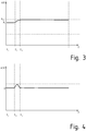
- Figure 3 shows in a schematic manner the surface size of a passivated sacrificial anode determined by the impedance measurement provided according to the invention in the water reservoir.
- a first change in the surface A (t) can be determined from a point in time t 31 , which is also expressed in the fact that the differential derivative according to Figure 4 is greater than zero.
- the enlargement of the sacrificial area stops very soon, namely at a level A max ' ⁇ A max , ie as extensive a surface enlargement as after Figure 1 was observed is nowhere near reached with a passivated, i.e. defective, sacrificial anode.
- such a fault condition in the cathodic protection system can be detected on the basis of passivation by activating an additional monitoring function for a certain period of time when the derivative function A '(t) has a zero value.
- the monitoring function is therefore preferably direct started after the reference measurement and aborted as soon as A '(t) ⁇ > 0. Whenever A' (t) subsequently equals zero again, the monitoring function is retriggered. Instead of a zero value, a very narrow value interval for A '(t) can also be defined around the zero point, which is equated with an apparently unchanged anode state.
- FIG. 5 shows a hot water tank 10 with an anode monitoring device 20.
- the hot water tank 10 comprises a metallic, internally enamelled container wall 11 with a hot water outlet 12, a cold water inlet 14 and a heating device 13, which can be an electric heating rod or a heat exchanger.
- a heating device 13 which can be an electric heating rod or a heat exchanger.
- In the bottom area there is a rod-shaped sacrificial anode 15 made of magnesium, which is always under water due to a level control.
- the sacrificial anode 15 is electrically insulated from the container wall 11.
- This structure is supplemented by a monitoring device 20.
- This is connected to the container wall 11 via an earth cable 22 and to the sacrificial anode 15 via a measuring line 21.
- the monitoring device 20 sends at least one high-frequency signal to the sacrificial anode 15 via a frequency generator, with which the impedance of the hot water tank 10 can be measured as an overall system.
- An operating and display unit 23 can be provided in order to be able to display the anode status to a user directly on the hot water tank 10 or to trigger the reference measurement after the anode has been replaced. However, it is also possible to provide a connection to a higher-level control unit of a heating system or to provide only an optical and / or acoustic fault indicator with which a malfunction of the sacrificial anode is signaled.
Landscapes
- Engineering & Computer Science (AREA)
- Physics & Mathematics (AREA)
- Chemical & Material Sciences (AREA)
- Mechanical Engineering (AREA)
- Thermal Sciences (AREA)
- General Engineering & Computer Science (AREA)
- Combustion & Propulsion (AREA)
- Life Sciences & Earth Sciences (AREA)
- Health & Medical Sciences (AREA)
- Immunology (AREA)
- Environmental & Geological Engineering (AREA)
- Environmental Sciences (AREA)
- Biodiversity & Conservation Biology (AREA)
- Analytical Chemistry (AREA)
- Biochemistry (AREA)
- General Health & Medical Sciences (AREA)
- General Physics & Mathematics (AREA)
- Ecology (AREA)
- Pathology (AREA)
- Materials Engineering (AREA)
- Metallurgy (AREA)
- Organic Chemistry (AREA)
- Prevention Of Electric Corrosion (AREA)
- Heat-Pump Type And Storage Water Heaters (AREA)
- Investigating Or Analyzing Materials By The Use Of Electric Means (AREA)
Abstract
Description
- Die Erfindung betrifft ein Verfahren zur Zustandsbestimmung einer Opferanode in einem Wasserspeicher.
- Warmwasserspeicher mit emaillierten Behältern sind in der Regel mit einem kathodischen Korrosionsschutzsystem ausgestattet, um die Korrosion des Behälters dauerhaft zu verringern. Fertigungsbedingt weist die Emaillierung stets Fehlstellen auf, an denen der Stahlbehälter im direkten Kontakt mit dem Elektrolyt steht. Kathodische Korrosionsschutzsysteme schützen diese Fehlstellen durch eine Potenzialverschiebung vor Korrosion. Bei Warmwasserspeichern wird der kathodische Korrosionsschutz üblicherweise durch Fremdstromanoden oder galvanische Opferanoden sichergestellt. Fremdstromanodensysteme sind wartungsfrei, benötigen allerdings eine unterbrechungsfreie Stromversorgung, um den Korrosionsschutz durchgehend zu gewährleisten. Galvanische Opferanoden wie beispielsweise Magnesiumanoden benötigen keine externe Stromversorgung, allerdings unterliegen sie einem fortwährenden Verbrauch des Anodenmaterials. Daher müssen Opferanoden regelmäßig kontrolliert und ausgetauscht werden, um einen durchgehenden Korrosionsschutz sicherzustellen.
- Um diese Wartung und den damit verbundenen Aufwand nur im Fall einer verbrauchten Anode durchführen zu müssen, können Warmwasserspeicher über Anzeigeeinrichtungen verfügen, die den Verbrauchszustand der Opferanode anzeigen. Für diese Anzeigeeinrichtungen werden spezielle Magnesiumanoden eingesetzt, die auch als Signalanoden bezeichnet werden. Signalanoden weisen einen hohlen Kanal im Inneren des Anodenstabs auf. Verbraucht sich das Anodenmaterial mit zunehmender Betriebszeit, so gelangt irgendwann Wasser in den Kanal und wird über diesen zu einem Sensor geleitet, der einen Druckschalter enthält, der über den einwirkenden Wasserdruck bei verbrauchter Opferanode mit offen liegendem inneren Kanal betätigt wird.
- Alternativ kann das in den Kanal eindringende Wasser eine Verfärbung einer Farbumschlagpille bewirken, die an einem von außen einsehbaren Schauglas sichtbar ist.
- Die vorgenannten Überwachungsvorrichtungen haben den Nachteil, dass sie nur ein digitales Signal liefern, das anliegt, wenn Wasser in den inneren Kanal eindringt. Dennoch kann eine erhebliche Restmasse des Materials des Opfermaterials vorhanden sein, die weiterhin für den Korrosionsschutz nutzbar ist. Der Verschleißzustand wird also zu früh angezeigt, so dass die theoretisch mögliche Standzeit der Opferanode nicht ausgenutzt wird.
- In der
DE 10 2004 004 064 B4 wird eine Vorrichtung zur Überwachung des Verbrauchs einer Opferanode beschrieben. Diese Vorrichtung verfügt über eine Schalteinrichtung, die den Strom der Magnesiumanode misst und mit einem Grenzwert vergleicht. - Die Internationale Veröffentlichung
WO 2007/010335 beschreibt einen Warmwasserspeicher mit einer Vorrichtung zur Überwachung der Opferanode, unter anderem durch Messung eines Anodenstroms und eine Potenzialmessung mittels einer Fremdstromanode, wozu zusätzliche Bauteile und elektrische Einrichtungen erforderlich sind. - Die Aufgabe der Erfindung besteht somit darin, ein Verfahren zur Zustandsbestimmung einer Opferanode in einem Wassertank anzugeben, mit dem erst dann ein Verschleißzustand der Opferanode signalisiert wird, wenn nur noch eine geringe Restmasse der Opferanode vorhanden ist und/oder den Verschleißzustand über die Lebensdauer überwachen zu können.
- Diese Aufgabe wird durch ein Verfahren zur Zustandsbestimmung einer Opferanode in einem Wasserspeicher mit den Merkmalen des Anspruchs 1 gelöst.
- Die Erfindung basiert auf einer Anwendung einer Impedanzmessung an der Opferanode über ein hochfrequentes Messsignal. Hierüber kann ein direkter Rückschluss auf den tatsächlichen Verbrauchszustand der Magnesiumanode gezogen werden.
- Die Erfindung geht von der Erkenntnis aus, dass sich in einer Grenzschicht zwischen dem Magnesiumwerkstoff der Opferanode bzw. einem anderen unedlen Metall und dem Elektrolyt eine sogenannte Helmholtz-Doppelschicht ausbildet oder ausprägt. Die Helmholtz-Doppelschicht besteht aus der genannten Helmholtzschicht und der entgegengesetzt geladenen Schicht in der Elektrode. Eine Helmholtzschicht ist ein schmaler Bereich innerhalb eines Elektrolyten, der direkt an eine Elektrode angrenzt und der eine Überschussladung trägt. Die metallische Elektrode besitzt in dem Bereich eine positive Überschussladung, die durch die Ladung der Anionen in der Helmholtzschicht auf der Elektrolytseite ausgeglichen wird. Durch die Ausrichtung aller elektrischen Teilchen in diesem Bereich ist dieser elektrisch nicht leitfähig und wirkt wie ein Kondensator. Folglich kann nach der Erfindung eine qualitative und quantitative Bewertung der Oberfläche der Opferanode mit den bekannten Methoden der Impedanz- bzw. Kapazitätsmessung durchgeführt werden. Die Kapazität des einem Kondensator ähnelnden Bereich ist abhängig von der Oberfläche der Anode. Die gemessene Kapazität und die Größe der Oberfläche der Opferanode können für den Zweck einer zuverlässigen Verschleißmessung im Warmwasserspeicher als direkt proportional angesehen werden, da die übrigen Einflüsse wie die chemische Zusammensetzung des Elektrolyten und auch die Temperatur im Warmwasserspeicher nahezu konstant sind. Eine große Anodenoberfläche ist also mit einer größeren Kapazität verknüpfbar als eine kleine Anodenoberfläche. Entsprechend kann über regelmäßige Messungen der Kapazität der Verschleißzustand der Anode bestimmt werden und erst bei Unterschreiten einer Mindestkapazität, die einer bestimmten Restoberfläche der Anode entspricht, ein Signal für den Verschleiß der Opferanode ausgegeben werden.
- Da die Opferanode im eingebauten Zustand im Wasserspeicher überwacht werden soll, kann die aus der Helmholtz-Doppelschicht resultierende Kapazität nicht direkt gemessen werden. Daher wird eine Impedanzmessung zwischen Opferanode und Behälterwand durchgeführt und es wird die Impedanz des gesamten Warmwasserspeichersystems bestehend aus Behälter, Opferanode und Elektrolyt gemessen. Die Impedanz beschreibt den Wechselstromwiderstand des Systems, dieser kann aus ohmschen, kapazitiven und induktiven Anteilen bestehen. Das hochfrequente Signal wird aber nur durch die Helmholtz-Doppelschicht beeinflusst, so dass die übrigen systembedingten Einflüsse der gemessenen Impedanz als konstant anzusehen ist und die gemessene Impedanz als proportional zur Kapazität an der Opferanode angesehen werden kann. Durch einen Vergleich des eingespeisten und des gemessenen Signals kann somit die Ausdehnung der Helmholtz-Doppelschicht und damit die wirksame Oberfläche der Opferanode quantitativ ermittelt werden.
- Ein wesentlicher Vorteil der vorliegenden Erfindung liegt also darin, dass der Lebenszyklus der Opferanode jederzeit nachzuverfolgen ist und erst bei nahezu vollständigem Verschleiß das Signal für den notwendigen Austausch der Opferanode abgegeben wird.
- In eine Basisausführung des Verfahrens reicht es aus, aus den fortlaufenden Messungen eine Tendenz abzuleiten und anhand bestimmter Erfahrungswerte oder Grenzwerte einen Zustand zu erfassen, bei dem ein Austausch der Opferanode notwendig wird.
- Möglich ist aber auch die quantitative Bestimmung der Kapazität oder der Anodenoberfläche, und zwar insbesondere durch einen Vergleich der temporären Messwerte mit Referenzmessungen, die entweder werksseitig oder vor Inbetriebnahme durchgeführt wurden. Indem bei der Inbetriebnahme des Wasserspeichers oder nach einem Austausch der Opferanode eine Referenzmessung der Impedanz vorgenommen wird, wird ein Referenzwert gesetzt, der z. B. als 100% der ursprünglichen Kapazität oder der ursprünglichen Oberfläche der Opferanode definiert ist. Die Wahl der Oberfläche hat den Vorteil, dass sie aus der bekannten Geometrie der Opferanode rechnerisch bestimmt werden kann und keine Referenzmessung notwendig ist.
- Eine weitere wichtige Erkenntnis für die vorliegende Erfindung ist, dass die zunehmende Zersetzung der Opferanode im Betrieb des Trinkwasserspeichers aufgrund der Herauslösung von oberflächennahen Bereichen zunächst zu einer Oberflächenvergrößerung an der Opferanode führt, was mit einer Erhöhung der Kapazität und demzufolge der messbaren Impedanz einhergeht. Erst wenn die ursprüngliche, meist zylindrische Geometrie der Opferanode weit zerstört ist, die Opferanode also deutlich kürzer geworden ist und/oder im Durchmesser abgenommen hat, heben sich die Effekte von Oberflächenvergrößerung durch Porosität und Oberflächenreduzierung durch Reduzierung der Geometrie auf, so dass vorübergehend eine Impedanz messbar ist, die dem ursprüngliche Referenzwert entspricht. Bereits dieser Punkt kann als Vorindikator für den Verschleiß genutzt werden. Es kann z. B. ein Signal für den Benutzer ausgeben werden oder das Messintervall für die nachfolgenden Impedanzmessungen verkürzt werden.
- Zur näheren Beschreibung der Erfindung wird auf die Zeichnungen Bezug genommen. Die Figuren zeigen im Einzelnen:
- Fig. 1
- den Verlauf der Oberflächengröße einer Opferanode über der Zeit;
- Fig. 2
- die Ableitungsfunktion zu dem Verlauf aus
Figur 1 und - Fig. 3
- einen weiteren Verlauf der Oberflächengröße einer Opferanode über der Zeit;
- Fig. 4
- die Ableitungsfunktion zu dem Verlauf aus
Figur 3 und - Fig. 5
- ein Warmwasserspeicher mit einer Anodenüberwachungseinrichtung in schematischer Ansicht.
- In
Figur 1 ist der exemplarische Verlauf des Zustands einer Magnesium-Opferanode in einem Wasserspeicher über der Zeit dargestellt, wobei in dem Beispiel als Zustandsindikator die Größe der Oberfläche A(t) des aus dem unedlen Anodenmaterial gebildeten Mantels der Opferanode gesetzt ist. - Bei der Inbetriebnahme zum Zeitpunkt t0 wird eine Referenzmessung der Impedanz der Opferanode durchgeführt und der Messwert mit einer relativen Anodenoberfläche A0 = 100% als Bezugswert definiert. Eine relative Bezugsgröße ist ausreichend, da sie für die Überwachung der kathodischen Schutzmaßnahmen ausreichend ist und quantitative Bestimmung nicht notwendig sind. Möglich ist auch, die aus der Fertigung bekannte konkrete Oberflächengröße als Referenzwert heranzuziehen.
- Aufgrund zunehmender Porosität infolge des im Betrieb des Warmwasserspeichers einsetzenden elektrolytischen Abbaus der Opferanode, erfolgt bis zum Zeitpunkt t1 eine Oberflächenvergrößerung Amax. Danach sinkt die über die periodische Impedanzmessung bestimmte Oberfläche A(t) wieder kontinuierlich ab. Zum Zeitpunkt t2 ist sie wieder beim Referenzwert A0 = 100% angelangt. Zum Zeitpunkt t3 ist die restliche Oberfläche der Opferanode so klein, dass ein notwendiger Austausch signalisiert wird.
- Eine besonders vorteilhafte Ausführungsform des erfindungsgemäßen Verfahrens sieht vor, nicht nur bei jeder Messung einen Vergleich mit dem Referenzwert vorzunehmen, sondern den zeitlichen Verlauf aller Messwerte für die Impedanz seit Inbetriebnahme aufzunehmen, daraus eine Näherungsfunktion zu bilden, insbesondere mit den bekannten Methoden der numerischen Analyse, und aus dieser wiederum zumindest eine differenzielle Ableitung davon zu bilden.
- Mittels der ersten differentiellen Ableitungsfunktion A'(t), die in
Figur 2 dargestellt ist, ist ohne die Notwendigkeit einer graphischen Darstellung und/oder einer Auswertung durch einen Benutzer die Entwicklung der Opferanode direkt charakterisierbar: - Ist der Wert der Ableitungsfunktion A'(t) positiv, liegt die Phase der Oberflächenvergrößerung zwischen t0 und t1 vor.
- Dann folgt ein Sattelpunkt mit einem Nulldurchgang der Ableitungsfunktion A'(t), der das temporäre Maximum der porösen Anodenoberfläche charakterisiert.
- Schließlich folgt ein negativer Wert der Ableitungsfunktion A'(t) entsprechend der Zersetzungsphase des Anodenkörpers zwischen t1 und t3.
- Eine weitere vorteilhafte Ausführungsform des Verfahrens nach der Erfindung sieht vor, auch den zeitlichen Verlauf der Ableitungsfunktion A'(t) zu beobachten, und zwar insbesondere dann, wenn ein Extremwert der Oberflächenfunktion A(t) erreicht wird, und bei der Ableitungsfunktion A'(t) den Wert null hat, wobei ein Sattelpunkt zu beobachten ist. Dieser Sattelpunkt kann auf den zu erwartenden Zustand der Oberflächenvergrößerung bei t1 hindeuten. Allerdings muss davor und danach eine Veränderung stattfinden, der Betrag der Ableitungsfunktion A'(t) also in einem gewissen Zeitintervall wieder ungleich null sein.
- Wenn diese erwartete Veränderung bei A'(t) jedoch über einen längeren Zeitraum nicht eintritt, so bedeutet das, dass an der Opferanode keine Oberflächenveränderung mehr stattfindet, was auf eine sogenannte Passivierung der Opferanode hindeutet. Das heißt, dass sich auf der gesamten Oberfläche der Anode eine chemisch inerte Oxidschicht ausgebildet oder abgelagert hat. Eine solche Passivierung ist selten, weil sie nur dann eintreten kann, wenn eine unerwartete chemische Konstellation im Trinkwassersystem vorliegt, an das der Wasserspeicher angebunden ist, z. B. wenn Ionen eines elektrochemisch gesehen unedleren Metalls wie Zink in Lösung sind. Jedoch führt die Passivierung der Opferanode immer dazu, dass der Wasserspeicher unbemerkt ohne wirksames kathodisches Schutzsystem betrieben wird und eine Zerstörung der metallischen Behälterwand unweigerlich eintreten wird, ohne dass sich die Geometrie der Opferanode geändert hat.
- Bei einer elektrisch nicht leitfähigen Passivierung auf der Opferanode, ist ein kapazitives Verhalten am Übergang der Anode zum Wasser ist weiterhin erfassbar. Die passivierende Schicht trennt die Anode vom Elektrolyt und stellt damit ebenfalls einen Kondensator da. Da bei der Passivierung der Anode keine Veränderung der Oberfläche mehr stattfindet, erfolgt keine Änderung der Impedanz über der Zeit.
-
Figur 3 zeigt in schematischer Weise den durch die nach der Erfindung vorgesehene Impedanzmessung in dem Wasserspeicher ermittelte Oberflächengröße einer passivierten Opferanode. Eine erste Veränderung der Oberfläche A(t) ist zwar ab einem Zeitpunkt t31 feststellbar, was sich auch darin äußert, dass die differentielle Ableitung gemäßFigur 4 größer als null ist. Jedoch ist zu beobachten, dass die Opferflächenvergrößerung schon sehr bald stoppt, und zwar auf einem Niveau Amax' < Amax, d.h. eine so weitgehende Oberflächenvergrößerung durch Porosität bei einer normalen Opferanode wie nachFigur 1 zu beobachten war, wird bei einer passivierten, also fehlerhaften Opferanode nicht annähernd erreicht. - In jedem Fall bleibt gemäß
Figur 3 die gemessene Oberfläche ab dem Zeitpunkt t32 auf dem einmal gemessenen Messwert und die Ableitung gemäßFigur 4 hat wieder den Wert null. Dies sind Indikatoren für ein funktionsunfähiges kathodisches Schutzsystem. - Mit dem Verfahren nach der Erfindung in der bevorzugten Ausführungsform kann ein solcher Störungszustand im kathodischen Schutzsystem aufgrund einer Passivierung erkannt werden, indem bei Vorliegen eines Nullwerts der Ableitungsfunktion A'(t) für eine bestimmte Zeitdauer eine zusätzliche Überwachungsfunktion aktiviert wird. Dies gilt nicht nur für einen Sattelpunkt im zeitlichen Verlauf des Betriebs, sondern insbesondere auch für den Fall, dass schon nach erstmaliger Inbetriebnahme des Wasserspeichers bzw. seines kathodischen Schutzsystem keinerlei Veränderung mehr registrierbar ist. Vorzugsweise wird die Überwachungsfunktion also direkt nach der Referenzmessung gestartet und abgebrochen, sobald A'(t) <> 0. Immer, wenn nachfolgend A'(t) nochmals gleich null ist, wird die Überwachungsfunktion neu getriggert. Anstelle eines Nullwertes kann auch um den Nullpunkt herum ein sehr schmales Werteintervall für A'(t) definiert sein, das mit einem scheinbar unveränderten Anodenzustand gleichgesetzt wird.
- Wird während der aktivierten Überwachungsfunktion keine Veränderung in der Oberflächenfunktion A(t) registriert bzw. bleibt die Ableitungsfunktion A'(t) null bzw. im Toleranzband nahe null, so deutet dies auf einen Störungszustand infolge Passivierung hin. Der Benutzer kann mittels eines Störungssignals aufgefordert werden, die Opferanode auszutauschen oder die oberflächennahe Oxidschicht mechanisch zu entfernen.
-
Figur 5 zeigt einen Warmwasserspeicher 10 mit einer Anodenüberwachungseinrichtung 20. Der Warmwasserspeicher 10 umfasst eine metallische, innen emaillierte Behälterwand 11 mit einem Warmwasserauslauf 12, einem Kaltwassereinlauf 14 und einer Heizeinrichtung 13, wobei es sich um einen elektrischen Heizstab oder einen Wärmetauscher handeln kann. Im Bodenbereich ist eine stabförmige Opferanode 15 aus Magnesium angeordnet, die aufgrund einer Füllstandsregelung stets unter Wasser liegt. Die Opferanode 15 ist von der Behälterwand 11 elektrisch isoliert. - Dieser an sich bekannte Aufbau wird durch eine Überwachungseinrichtung 20 ergänzt. Diese ist über ein Massekabel 22 mit der Behälterwand 11 und über eine Messleitung 21 mit der Opferanode 15 verbunden. Die Überwachungseinrichtung 20 gibt über einen Frequenzgenerator wenigstens ein hochfrequentes Signal auf die Opferanode 15, mit welchem die Impedanz des Warmwasserspeichers 10 als Gesamtsystem gemessen werden kann.
- Eine Bedien- und Anzeigeeinheit 23 kann vorgesehen sein, um einem Benutzer direkt am Warmwasserspeicher 10 den Anodenzustand anzeigen zu können oder die Referenzmessung nach Anodenaustausch auszulösen. Möglich ist aber auch, eine Verbindung zu einer übergeordneten Steuerungseinheit einer Heizungsanlage vorzusehen oder allein eine optische und/oder akustische Störungsanzeige vorzusehen, mit der eine Fehlfunktion der Opferanode signalisiert wird.
Claims (8)
- Verfahren zur Zustandsbestimmung einer Opferanode (15) in einem Wasserspeicher (10) mit folgenden Schritten- Beaufschlagen der Opferanode (15) mit einem hochfrequenten elektrischen Wechselstromsignal;- Wiederholte Messung der Impedanz im Warmwasserspeicher (10) in dem zwischen der Opferanode (15) und einer metallischen Behälterwand (11) ausgebildeten Stromkreis und Definition eines Zustandsindikators der Opferanode (15) mit dem erhaltenen Impedanz-Messwert;- Signalisierung eines Abnutzungszustands der Opferanode (15) nach Unterschreiten eines Grenzwertes bei dem Zustandsindikator und/oder bei Ausfall der Impedanzmessung.
- Verfahren nach Anspruch 1, dadurch gekennzeichnet, dass bei Inbetriebnahme des Wasserspeichers (10) oder nach Austausch der Opferanode (15) eine Referenzmessung der Impedanz zum Zeitpunkt t0 durchgeführt wird, und dass zur Bildung eines temporären Zustandsindikators die während des Betriebs des Warmwasserspeichers (10) aufgenommenen Messwerte jeweils in Relation zu dem bei der Referenzmessung aufgenommenen Referenzwert gesetzt werden.
- Verfahren nach Anspruch 2, dadurch gekennzeichnet, dass als Zustandsindikator der Opferanode (15) die Kapazität der Opferanode (15) gesetzt wird, wobei die bei den wiederholten Messungen der Impedanz ermittelten Messwerte jeweils in Relation zu der bei der Referenzmessung ermittelten Ausgangsgröße der Kapazität gesetzt werden.
- Verfahren nach Anspruch 2, dadurch gekennzeichnet, dass als Zustandsindikator der Opferanode (15) die Oberfläche A der Opferanode (15) gesetzt wird, wobei die bei den wiederholten Messungen der Impedanz ermittelten Messwerte jeweils in Relation zu der bei der Referenzmessung ermittelten Ausgangsgröße A0 der Oberfläche gesetzt werden.
- Verfahren nach einem der Ansprüche 1 bis 4, dadurch gekennzeichnet, dass aus den mit den wiederholten Messungen ermittelten Messwerten eine angenäherte Zustandsfunktion A(t) für den Zustand der Opferanode ermittelt wird und eine erste differentielle Ableitung A'(t) der Zustandsfunktion A(t) gebildet wird.
- Verfahren nach Anspruch 5, dadurch gekennzeichnet, dass eine Überwachungsfunktion für einen Überwachungszeitraum tÜ gestartet wird, sobald die differentielle Ableitung A'(t) null oder kleiner als ein Mindestwert ist, wobei- entweder die Überwachungsfunktion beendet wird, sobald die differentielle Ableitung A'(t) größer null oder größer als der Mindestwert ist,- oder ein Störungszustand nach Ablauf des Überwachungszeitraums signalisiert wird.
- Verfahren nach einem der Ansprüche 1 bis 6, dadurch gekennzeichnet, dass die Impedanzmessung jeweils mit wenigstens zwei unterschiedlichen Messfrequenzen mehrfach durchgeführt wird und ein Mittelwert aus allen Messungen als Messwert für den Zustandsindikator gesetzt wird.
- Warmwasserspeicher (10) zur Durchführung des Verfahrens nach einem der vorhergehenden Ansprüche, wenigstens umfassend:- eine metallischen Behälterwand (11),- einen Warmwasserauslauf (12);- einer Heizeinrichtung (13);- einen Kaltwassereinlauf (14) und- eine metallischen Opferanode (15)gekennzeichnet durch eine Anodenüberwachungseinrichtung (20), die eine Impedanzmesseinheit mit einem Frequenzgenerator zur Erzeugung eines hochfrequenten elektrischen Wechselstromsignals umfasst, wobei die Impedanzmesseinheit mit einem Pol mit der Opferanode (15) und mit dem anderen Pol mit der metallischen Behälterwand (11) verbunden ist.
Applications Claiming Priority (1)
| Application Number | Priority Date | Filing Date | Title |
|---|---|---|---|
| DE102020100808.2A DE102020100808A1 (de) | 2020-01-15 | 2020-01-15 | Verfahren zur Zustandsbestimmung einer Opferanode in einem Wasserspeicher |
Publications (2)
| Publication Number | Publication Date |
|---|---|
| EP3851830A1 true EP3851830A1 (de) | 2021-07-21 |
| EP3851830B1 EP3851830B1 (de) | 2024-05-01 |
Family
ID=74130142
Family Applications (1)
| Application Number | Title | Priority Date | Filing Date |
|---|---|---|---|
| EP21151000.3A Active EP3851830B1 (de) | 2020-01-15 | 2021-01-11 | Verfahren zur zustandsbestimmung einer opferanode in einem wasserspeicher |
Country Status (3)
| Country | Link |
|---|---|
| EP (1) | EP3851830B1 (de) |
| DE (1) | DE102020100808A1 (de) |
| PL (1) | PL3851830T3 (de) |
Citations (4)
| Publication number | Priority date | Publication date | Assignee | Title |
|---|---|---|---|---|
| WO2007010335A2 (en) | 2005-07-20 | 2007-01-25 | Merloni Termosanitari S.P.A. | Accumulator water heater with adjustable cathodic protection |
| DE102008013943A1 (de) * | 2008-03-12 | 2009-09-17 | Stiebel Eltron Gmbh & Co. Kg | Warmwasserspeicher und Testvorrichtung zum Testen einer Anode in einem Warmwasserspeicher |
| JP2011075492A (ja) * | 2009-10-01 | 2011-04-14 | Tokyo Institute Of Technology | 金属体の断面形状測定装置 |
| DE102004004064B4 (de) | 2003-01-29 | 2017-04-13 | Vaillant Gmbh | Vorrichtung zur Überwachung des Verbrachs einer Opferanode |
Family Cites Families (1)
| Publication number | Priority date | Publication date | Assignee | Title |
|---|---|---|---|---|
| DE102015016247B3 (de) * | 2015-12-16 | 2017-04-13 | Stiebel Eltron Gmbh & Co. Kg | Heizeinrichtung |
-
2020
- 2020-01-15 DE DE102020100808.2A patent/DE102020100808A1/de active Pending
-
2021
- 2021-01-11 PL PL21151000.3T patent/PL3851830T3/pl unknown
- 2021-01-11 EP EP21151000.3A patent/EP3851830B1/de active Active
Patent Citations (4)
| Publication number | Priority date | Publication date | Assignee | Title |
|---|---|---|---|---|
| DE102004004064B4 (de) | 2003-01-29 | 2017-04-13 | Vaillant Gmbh | Vorrichtung zur Überwachung des Verbrachs einer Opferanode |
| WO2007010335A2 (en) | 2005-07-20 | 2007-01-25 | Merloni Termosanitari S.P.A. | Accumulator water heater with adjustable cathodic protection |
| DE102008013943A1 (de) * | 2008-03-12 | 2009-09-17 | Stiebel Eltron Gmbh & Co. Kg | Warmwasserspeicher und Testvorrichtung zum Testen einer Anode in einem Warmwasserspeicher |
| JP2011075492A (ja) * | 2009-10-01 | 2011-04-14 | Tokyo Institute Of Technology | 金属体の断面形状測定装置 |
Also Published As
| Publication number | Publication date |
|---|---|
| DE102020100808A1 (de) | 2021-07-15 |
| EP3851830B1 (de) | 2024-05-01 |
| PL3851830T3 (pl) | 2024-09-09 |
Similar Documents
| Publication | Publication Date | Title |
|---|---|---|
| DE3782000T2 (de) | Verfahren und vorrichtung zur ionisation von fluessigkeiten. | |
| DE102013104781A1 (de) | Verfahren zur Überwachung zumindest einer medienspezifischen Eigenschaft eines Mediums | |
| DE2407081C3 (de) | Verfahren und Anordnung zum Nachweisen der Ablagerung von Kesselstein oder einer anderen anhaftenden Substanz aus einer Flüssigkeit | |
| EP2533036B1 (de) | Verfahren zum Betrieb eines Leitfähigkeitssensors, insbesondere zur Reinigung der Elektrodenoberflächen des Leitfähigkeitssensors, und Wasserenthärter enthaltend einen solchen Leitfähigkeitssensor | |
| DE2751925C2 (de) | ||
| CH657385A5 (de) | Verfahren zur elektrolytischen entfernung von nickel-, chrom- oder goldschichten von kupfer- oder kupferlegierungsflaechen und einrichtung zu dessen durchfuehrung. | |
| EP1350091B1 (de) | Verfahren zur bestimmung einer restbetriebsdauer einer potentiometrischen messsonde, vorrichtung zur durchführung des verfahrens und ihre verwendung | |
| EP0472057B1 (de) | Anordnung und Verfahren zur Erzielung eines kathodischen Korrosionsschutzes | |
| EP3866937B1 (de) | Verfahren zur überwachung der qualität von löschwasser in sprinkleranlagen sowie sprinklerkopf | |
| EP3851830B1 (de) | Verfahren zur zustandsbestimmung einer opferanode in einem wasserspeicher | |
| DE2325726A1 (de) | Verfahren und vorrichtung zur pruefung der auskleidung von reaktionskesseln | |
| DE4101404C2 (de) | ||
| DE10145575A1 (de) | Warmwasserspeicher | |
| DE69802572T2 (de) | Verfahren zur Überwachung der Elektrolytumwälzung in einer Elektrolysezelle | |
| DE19840471A1 (de) | Einrichtung zum Abtrag einer Beschichtung von Gegenständen | |
| DE2114972A1 (de) | Verfahren zum Abgleich einer Dunn filmanordnung | |
| DE2241648A1 (de) | Verfahren zur messung des schutzpotentials kathodisch geschuetzter objekte | |
| EP3218633A1 (de) | Förderschlauch | |
| DE2547734C3 (de) | Verfahren und Vorrichtung zum Nachformieren von Trocken-Elektrolytkondensatoren | |
| DE69206157T2 (de) | Verfahren und vorrichtung zum erhalten kathodischen schutzes gegen korrosion. | |
| DE19537059A1 (de) | Anordnung zum berührungslosen Messen der spezifischen Leitfähigkeit wäßriger Lösungen | |
| DE202011102629U1 (de) | Leitfähigkeitssensorstation mit Reinigungsfunktion für die Elektrodenoberflächen des Leitfähigkeitssensors | |
| DE3244903A1 (de) | Schnelle thermoelement-niveauregulierung | |
| DE102008013943B4 (de) | Warmwasserspeicher und Testvorrichtung zum Testen einer Anode in einem Warmwasserspeicher | |
| DE112019005037T5 (de) | Untersuchungsverfahren und Untersuchungssystem für einen Stator |
Legal Events
| Date | Code | Title | Description |
|---|---|---|---|
| PUAI | Public reference made under article 153(3) epc to a published international application that has entered the european phase |
Free format text: ORIGINAL CODE: 0009012 |
|
| STAA | Information on the status of an ep patent application or granted ep patent |
Free format text: STATUS: THE APPLICATION HAS BEEN PUBLISHED |
|
| AK | Designated contracting states |
Kind code of ref document: A1 Designated state(s): AL AT BE BG CH CY CZ DE DK EE ES FI FR GB GR HR HU IE IS IT LI LT LU LV MC MK MT NL NO PL PT RO RS SE SI SK SM TR |
|
| STAA | Information on the status of an ep patent application or granted ep patent |
Free format text: STATUS: REQUEST FOR EXAMINATION WAS MADE |
|
| 17P | Request for examination filed |
Effective date: 20220121 |
|
| RBV | Designated contracting states (corrected) |
Designated state(s): AL AT BE BG CH CY CZ DE DK EE ES FI FR GB GR HR HU IE IS IT LI LT LU LV MC MK MT NL NO PL PT RO RS SE SI SK SM TR |
|
| P01 | Opt-out of the competence of the unified patent court (upc) registered |
Effective date: 20230524 |
|
| GRAP | Despatch of communication of intention to grant a patent |
Free format text: ORIGINAL CODE: EPIDOSNIGR1 |
|
| STAA | Information on the status of an ep patent application or granted ep patent |
Free format text: STATUS: GRANT OF PATENT IS INTENDED |
|
| RIC1 | Information provided on ipc code assigned before grant |
Ipc: F28D 20/00 20060101ALI20231116BHEP Ipc: F28F 19/00 20060101ALI20231116BHEP Ipc: F24H 9/45 20220101ALI20231116BHEP Ipc: C23F 13/22 20060101ALI20231116BHEP Ipc: G01N 17/02 20060101AFI20231116BHEP |
|
| INTG | Intention to grant announced |
Effective date: 20231130 |
|
| GRAS | Grant fee paid |
Free format text: ORIGINAL CODE: EPIDOSNIGR3 |
|
| GRAA | (expected) grant |
Free format text: ORIGINAL CODE: 0009210 |
|
| STAA | Information on the status of an ep patent application or granted ep patent |
Free format text: STATUS: THE PATENT HAS BEEN GRANTED |
|
| AK | Designated contracting states |
Kind code of ref document: B1 Designated state(s): AL AT BE BG CH CY CZ DE DK EE ES FI FR GB GR HR HU IE IS IT LI LT LU LV MC MK MT NL NO PL PT RO RS SE SI SK SM TR |
|
| REG | Reference to a national code |
Ref country code: GB Ref legal event code: FG4D Free format text: NOT ENGLISH |
|
| REG | Reference to a national code |
Ref country code: CH Ref legal event code: EP |
|
| REG | Reference to a national code |
Ref country code: DE Ref legal event code: R096 Ref document number: 502021003513 Country of ref document: DE |
|
| REG | Reference to a national code |
Ref country code: IE Ref legal event code: FG4D Free format text: LANGUAGE OF EP DOCUMENT: GERMAN |
|
| REG | Reference to a national code |
Ref country code: LT Ref legal event code: MG9D |
|
| REG | Reference to a national code |
Ref country code: NL Ref legal event code: MP Effective date: 20240501 |
|
| PG25 | Lapsed in a contracting state [announced via postgrant information from national office to epo] |
Ref country code: IS Free format text: LAPSE BECAUSE OF FAILURE TO SUBMIT A TRANSLATION OF THE DESCRIPTION OR TO PAY THE FEE WITHIN THE PRESCRIBED TIME-LIMIT Effective date: 20240901 |
|
| PG25 | Lapsed in a contracting state [announced via postgrant information from national office to epo] |
Ref country code: BG Free format text: LAPSE BECAUSE OF FAILURE TO SUBMIT A TRANSLATION OF THE DESCRIPTION OR TO PAY THE FEE WITHIN THE PRESCRIBED TIME-LIMIT Effective date: 20240501 |
|
| PG25 | Lapsed in a contracting state [announced via postgrant information from national office to epo] |
Ref country code: FI Free format text: LAPSE BECAUSE OF FAILURE TO SUBMIT A TRANSLATION OF THE DESCRIPTION OR TO PAY THE FEE WITHIN THE PRESCRIBED TIME-LIMIT Effective date: 20240501 Ref country code: HR Free format text: LAPSE BECAUSE OF FAILURE TO SUBMIT A TRANSLATION OF THE DESCRIPTION OR TO PAY THE FEE WITHIN THE PRESCRIBED TIME-LIMIT Effective date: 20240501 |
|
| PG25 | Lapsed in a contracting state [announced via postgrant information from national office to epo] |
Ref country code: GR Free format text: LAPSE BECAUSE OF FAILURE TO SUBMIT A TRANSLATION OF THE DESCRIPTION OR TO PAY THE FEE WITHIN THE PRESCRIBED TIME-LIMIT Effective date: 20240802 |
|
| PG25 | Lapsed in a contracting state [announced via postgrant information from national office to epo] |
Ref country code: PT Free format text: LAPSE BECAUSE OF FAILURE TO SUBMIT A TRANSLATION OF THE DESCRIPTION OR TO PAY THE FEE WITHIN THE PRESCRIBED TIME-LIMIT Effective date: 20240902 |
|
| PG25 | Lapsed in a contracting state [announced via postgrant information from national office to epo] |
Ref country code: NL Free format text: LAPSE BECAUSE OF FAILURE TO SUBMIT A TRANSLATION OF THE DESCRIPTION OR TO PAY THE FEE WITHIN THE PRESCRIBED TIME-LIMIT Effective date: 20240501 |
|
| PG25 | Lapsed in a contracting state [announced via postgrant information from national office to epo] |
Ref country code: ES Free format text: LAPSE BECAUSE OF FAILURE TO SUBMIT A TRANSLATION OF THE DESCRIPTION OR TO PAY THE FEE WITHIN THE PRESCRIBED TIME-LIMIT Effective date: 20240501 |
|
| PG25 | Lapsed in a contracting state [announced via postgrant information from national office to epo] |
Ref country code: LV Free format text: LAPSE BECAUSE OF FAILURE TO SUBMIT A TRANSLATION OF THE DESCRIPTION OR TO PAY THE FEE WITHIN THE PRESCRIBED TIME-LIMIT Effective date: 20240501 |
|
| PG25 | Lapsed in a contracting state [announced via postgrant information from national office to epo] |
Ref country code: PT Free format text: LAPSE BECAUSE OF FAILURE TO SUBMIT A TRANSLATION OF THE DESCRIPTION OR TO PAY THE FEE WITHIN THE PRESCRIBED TIME-LIMIT Effective date: 20240902 Ref country code: NO Free format text: LAPSE BECAUSE OF FAILURE TO SUBMIT A TRANSLATION OF THE DESCRIPTION OR TO PAY THE FEE WITHIN THE PRESCRIBED TIME-LIMIT Effective date: 20240801 Ref country code: NL Free format text: LAPSE BECAUSE OF FAILURE TO SUBMIT A TRANSLATION OF THE DESCRIPTION OR TO PAY THE FEE WITHIN THE PRESCRIBED TIME-LIMIT Effective date: 20240501 Ref country code: LV Free format text: LAPSE BECAUSE OF FAILURE TO SUBMIT A TRANSLATION OF THE DESCRIPTION OR TO PAY THE FEE WITHIN THE PRESCRIBED TIME-LIMIT Effective date: 20240501 Ref country code: IS Free format text: LAPSE BECAUSE OF FAILURE TO SUBMIT A TRANSLATION OF THE DESCRIPTION OR TO PAY THE FEE WITHIN THE PRESCRIBED TIME-LIMIT Effective date: 20240901 Ref country code: HR Free format text: LAPSE BECAUSE OF FAILURE TO SUBMIT A TRANSLATION OF THE DESCRIPTION OR TO PAY THE FEE WITHIN THE PRESCRIBED TIME-LIMIT Effective date: 20240501 Ref country code: GR Free format text: LAPSE BECAUSE OF FAILURE TO SUBMIT A TRANSLATION OF THE DESCRIPTION OR TO PAY THE FEE WITHIN THE PRESCRIBED TIME-LIMIT Effective date: 20240802 Ref country code: FI Free format text: LAPSE BECAUSE OF FAILURE TO SUBMIT A TRANSLATION OF THE DESCRIPTION OR TO PAY THE FEE WITHIN THE PRESCRIBED TIME-LIMIT Effective date: 20240501 Ref country code: ES Free format text: LAPSE BECAUSE OF FAILURE TO SUBMIT A TRANSLATION OF THE DESCRIPTION OR TO PAY THE FEE WITHIN THE PRESCRIBED TIME-LIMIT Effective date: 20240501 Ref country code: BG Free format text: LAPSE BECAUSE OF FAILURE TO SUBMIT A TRANSLATION OF THE DESCRIPTION OR TO PAY THE FEE WITHIN THE PRESCRIBED TIME-LIMIT Effective date: 20240501 Ref country code: RS Free format text: LAPSE BECAUSE OF FAILURE TO SUBMIT A TRANSLATION OF THE DESCRIPTION OR TO PAY THE FEE WITHIN THE PRESCRIBED TIME-LIMIT Effective date: 20240801 |
|
| PG25 | Lapsed in a contracting state [announced via postgrant information from national office to epo] |
Ref country code: DK Free format text: LAPSE BECAUSE OF FAILURE TO SUBMIT A TRANSLATION OF THE DESCRIPTION OR TO PAY THE FEE WITHIN THE PRESCRIBED TIME-LIMIT Effective date: 20240501 |
|
| PG25 | Lapsed in a contracting state [announced via postgrant information from national office to epo] |
Ref country code: EE Free format text: LAPSE BECAUSE OF FAILURE TO SUBMIT A TRANSLATION OF THE DESCRIPTION OR TO PAY THE FEE WITHIN THE PRESCRIBED TIME-LIMIT Effective date: 20240501 |
|
| PG25 | Lapsed in a contracting state [announced via postgrant information from national office to epo] |
Ref country code: CZ Free format text: LAPSE BECAUSE OF FAILURE TO SUBMIT A TRANSLATION OF THE DESCRIPTION OR TO PAY THE FEE WITHIN THE PRESCRIBED TIME-LIMIT Effective date: 20240501 |
|
| PG25 | Lapsed in a contracting state [announced via postgrant information from national office to epo] |
Ref country code: RO Free format text: LAPSE BECAUSE OF FAILURE TO SUBMIT A TRANSLATION OF THE DESCRIPTION OR TO PAY THE FEE WITHIN THE PRESCRIBED TIME-LIMIT Effective date: 20240501 Ref country code: SK Free format text: LAPSE BECAUSE OF FAILURE TO SUBMIT A TRANSLATION OF THE DESCRIPTION OR TO PAY THE FEE WITHIN THE PRESCRIBED TIME-LIMIT Effective date: 20240501 |
|
| PG25 | Lapsed in a contracting state [announced via postgrant information from national office to epo] |
Ref country code: SM Free format text: LAPSE BECAUSE OF FAILURE TO SUBMIT A TRANSLATION OF THE DESCRIPTION OR TO PAY THE FEE WITHIN THE PRESCRIBED TIME-LIMIT Effective date: 20240501 |
|
| PG25 | Lapsed in a contracting state [announced via postgrant information from national office to epo] |
Ref country code: SM Free format text: LAPSE BECAUSE OF FAILURE TO SUBMIT A TRANSLATION OF THE DESCRIPTION OR TO PAY THE FEE WITHIN THE PRESCRIBED TIME-LIMIT Effective date: 20240501 Ref country code: SK Free format text: LAPSE BECAUSE OF FAILURE TO SUBMIT A TRANSLATION OF THE DESCRIPTION OR TO PAY THE FEE WITHIN THE PRESCRIBED TIME-LIMIT Effective date: 20240501 Ref country code: RO Free format text: LAPSE BECAUSE OF FAILURE TO SUBMIT A TRANSLATION OF THE DESCRIPTION OR TO PAY THE FEE WITHIN THE PRESCRIBED TIME-LIMIT Effective date: 20240501 Ref country code: EE Free format text: LAPSE BECAUSE OF FAILURE TO SUBMIT A TRANSLATION OF THE DESCRIPTION OR TO PAY THE FEE WITHIN THE PRESCRIBED TIME-LIMIT Effective date: 20240501 Ref country code: DK Free format text: LAPSE BECAUSE OF FAILURE TO SUBMIT A TRANSLATION OF THE DESCRIPTION OR TO PAY THE FEE WITHIN THE PRESCRIBED TIME-LIMIT Effective date: 20240501 Ref country code: CZ Free format text: LAPSE BECAUSE OF FAILURE TO SUBMIT A TRANSLATION OF THE DESCRIPTION OR TO PAY THE FEE WITHIN THE PRESCRIBED TIME-LIMIT Effective date: 20240501 |
|
| REG | Reference to a national code |
Ref country code: DE Ref legal event code: R097 Ref document number: 502021003513 Country of ref document: DE |
|
| PG25 | Lapsed in a contracting state [announced via postgrant information from national office to epo] |
Ref country code: IT Free format text: LAPSE BECAUSE OF FAILURE TO SUBMIT A TRANSLATION OF THE DESCRIPTION OR TO PAY THE FEE WITHIN THE PRESCRIBED TIME-LIMIT Effective date: 20240501 |
|
| PLBE | No opposition filed within time limit |
Free format text: ORIGINAL CODE: 0009261 |
|
| STAA | Information on the status of an ep patent application or granted ep patent |
Free format text: STATUS: NO OPPOSITION FILED WITHIN TIME LIMIT |
|
| 26N | No opposition filed |
Effective date: 20250204 |
|
| PG25 | Lapsed in a contracting state [announced via postgrant information from national office to epo] |
Ref country code: SI Free format text: LAPSE BECAUSE OF FAILURE TO SUBMIT A TRANSLATION OF THE DESCRIPTION OR TO PAY THE FEE WITHIN THE PRESCRIBED TIME-LIMIT Effective date: 20240501 |
|
| REG | Reference to a national code |
Ref country code: CH Ref legal event code: PL |
|
| PG25 | Lapsed in a contracting state [announced via postgrant information from national office to epo] |
Ref country code: SE Free format text: LAPSE BECAUSE OF FAILURE TO SUBMIT A TRANSLATION OF THE DESCRIPTION OR TO PAY THE FEE WITHIN THE PRESCRIBED TIME-LIMIT Effective date: 20240501 |
|
| PG25 | Lapsed in a contracting state [announced via postgrant information from national office to epo] |
Ref country code: MC Free format text: LAPSE BECAUSE OF FAILURE TO SUBMIT A TRANSLATION OF THE DESCRIPTION OR TO PAY THE FEE WITHIN THE PRESCRIBED TIME-LIMIT Effective date: 20240501 Ref country code: LU Free format text: LAPSE BECAUSE OF NON-PAYMENT OF DUE FEES Effective date: 20250111 |
|
| GBPC | Gb: european patent ceased through non-payment of renewal fee |
Effective date: 20250111 |
|
| PG25 | Lapsed in a contracting state [announced via postgrant information from national office to epo] |
Ref country code: BE Free format text: LAPSE BECAUSE OF NON-PAYMENT OF DUE FEES Effective date: 20250131 Ref country code: GB Free format text: LAPSE BECAUSE OF NON-PAYMENT OF DUE FEES Effective date: 20250111 |
|
| PG25 | Lapsed in a contracting state [announced via postgrant information from national office to epo] |
Ref country code: CH Free format text: LAPSE BECAUSE OF NON-PAYMENT OF DUE FEES Effective date: 20250131 |
|
| REG | Reference to a national code |
Ref country code: BE Ref legal event code: MM Effective date: 20250131 |
|
| PG25 | Lapsed in a contracting state [announced via postgrant information from national office to epo] |
Ref country code: IE Free format text: LAPSE BECAUSE OF NON-PAYMENT OF DUE FEES Effective date: 20250111 |
|
| PGFP | Annual fee paid to national office [announced via postgrant information from national office to epo] |
Ref country code: DE Payment date: 20260121 Year of fee payment: 6 |
|
| PGFP | Annual fee paid to national office [announced via postgrant information from national office to epo] |
Ref country code: AT Payment date: 20260122 Year of fee payment: 6 |
|
| PGFP | Annual fee paid to national office [announced via postgrant information from national office to epo] |
Ref country code: FR Payment date: 20260123 Year of fee payment: 6 |
|
| PGFP | Annual fee paid to national office [announced via postgrant information from national office to epo] |
Ref country code: PL Payment date: 20251231 Year of fee payment: 6 |