EP3851247B1 - Reinigungsanlage sowie reinigungsverfahren - Google Patents
Reinigungsanlage sowie reinigungsverfahren Download PDFInfo
- Publication number
- EP3851247B1 EP3851247B1 EP20210540.9A EP20210540A EP3851247B1 EP 3851247 B1 EP3851247 B1 EP 3851247B1 EP 20210540 A EP20210540 A EP 20210540A EP 3851247 B1 EP3851247 B1 EP 3851247B1
- Authority
- EP
- European Patent Office
- Prior art keywords
- robot
- unit
- mould
- distance
- cleaning system
- Prior art date
- Legal status (The legal status is an assumption and is not a legal conclusion. Google has not performed a legal analysis and makes no representation as to the accuracy of the status listed.)
- Active
Links
Images

Classifications
-
- B—PERFORMING OPERATIONS; TRANSPORTING
- B25—HAND TOOLS; PORTABLE POWER-DRIVEN TOOLS; MANIPULATORS
- B25J—MANIPULATORS; CHAMBERS PROVIDED WITH MANIPULATION DEVICES
- B25J21/00—Chambers provided with manipulation devices
-
- B—PERFORMING OPERATIONS; TRANSPORTING
- B24—GRINDING; POLISHING
- B24C—ABRASIVE OR RELATED BLASTING WITH PARTICULATE MATERIAL
- B24C1/00—Methods for use of abrasive blasting for producing particular effects; Use of auxiliary equipment in connection with such methods
- B24C1/003—Methods for use of abrasive blasting for producing particular effects; Use of auxiliary equipment in connection with such methods using material which dissolves or changes phase after the treatment, e.g. ice, CO2
-
- B—PERFORMING OPERATIONS; TRANSPORTING
- B24—GRINDING; POLISHING
- B24C—ABRASIVE OR RELATED BLASTING WITH PARTICULATE MATERIAL
- B24C3/00—Abrasive blasting machines or devices; Plants
- B24C3/02—Abrasive blasting machines or devices; Plants characterised by the arrangement of the component assemblies with respect to each other
- B24C3/06—Abrasive blasting machines or devices; Plants characterised by the arrangement of the component assemblies with respect to each other movable; portable
-
- B—PERFORMING OPERATIONS; TRANSPORTING
- B24—GRINDING; POLISHING
- B24C—ABRASIVE OR RELATED BLASTING WITH PARTICULATE MATERIAL
- B24C3/00—Abrasive blasting machines or devices; Plants
- B24C3/32—Abrasive blasting machines or devices; Plants designed for abrasive blasting of particular work, e.g. the internal surfaces of cylinder blocks
- B24C3/325—Abrasive blasting machines or devices; Plants designed for abrasive blasting of particular work, e.g. the internal surfaces of cylinder blocks for internal surfaces, e.g. of tubes
-
- B—PERFORMING OPERATIONS; TRANSPORTING
- B25—HAND TOOLS; PORTABLE POWER-DRIVEN TOOLS; MANIPULATORS
- B25J—MANIPULATORS; CHAMBERS PROVIDED WITH MANIPULATION DEVICES
- B25J11/00—Manipulators not otherwise provided for
- B25J11/008—Manipulators for service tasks
- B25J11/0085—Cleaning
-
- B—PERFORMING OPERATIONS; TRANSPORTING
- B25—HAND TOOLS; PORTABLE POWER-DRIVEN TOOLS; MANIPULATORS
- B25J—MANIPULATORS; CHAMBERS PROVIDED WITH MANIPULATION DEVICES
- B25J19/00—Accessories fitted to manipulators, e.g. for monitoring, for viewing; Safety devices combined with or specially adapted for use in connection with manipulators
- B25J19/02—Sensing devices
- B25J19/021—Optical sensing devices
- B25J19/023—Optical sensing devices including video camera means
-
- B—PERFORMING OPERATIONS; TRANSPORTING
- B29—WORKING OF PLASTICS; WORKING OF SUBSTANCES IN A PLASTIC STATE IN GENERAL
- B29C—SHAPING OR JOINING OF PLASTICS; SHAPING OF MATERIAL IN A PLASTIC STATE, NOT OTHERWISE PROVIDED FOR; AFTER-TREATMENT OF THE SHAPED PRODUCTS, e.g. REPAIRING
- B29C33/00—Moulds or cores; Details thereof or accessories therefor
- B29C33/70—Maintenance
- B29C33/72—Cleaning
-
- B—PERFORMING OPERATIONS; TRANSPORTING
- B29—WORKING OF PLASTICS; WORKING OF SUBSTANCES IN A PLASTIC STATE IN GENERAL
- B29D—PRODUCING PARTICULAR ARTICLES FROM PLASTICS OR FROM SUBSTANCES IN A PLASTIC STATE
- B29D30/00—Producing pneumatic or solid tyres or parts thereof
- B29D30/06—Pneumatic tyres or parts thereof (e.g. produced by casting, moulding, compression moulding, injection moulding, centrifugal casting)
- B29D30/0601—Vulcanising tyres; Vulcanising presses for tyres
- B29D30/0662—Accessories, details or auxiliary operations
-
- G—PHYSICS
- G01—MEASURING; TESTING
- G01B—MEASURING LENGTH, THICKNESS OR SIMILAR LINEAR DIMENSIONS; MEASURING ANGLES; MEASURING AREAS; MEASURING IRREGULARITIES OF SURFACES OR CONTOURS
- G01B11/00—Measuring arrangements characterised by the use of optical techniques
- G01B11/002—Measuring arrangements characterised by the use of optical techniques for measuring two or more coordinates
-
- G—PHYSICS
- G01—MEASURING; TESTING
- G01B—MEASURING LENGTH, THICKNESS OR SIMILAR LINEAR DIMENSIONS; MEASURING ANGLES; MEASURING AREAS; MEASURING IRREGULARITIES OF SURFACES OR CONTOURS
- G01B11/00—Measuring arrangements characterised by the use of optical techniques
- G01B11/02—Measuring arrangements characterised by the use of optical techniques for measuring length, width or thickness
- G01B11/026—Measuring arrangements characterised by the use of optical techniques for measuring length, width or thickness by measuring distance between sensor and object
-
- B—PERFORMING OPERATIONS; TRANSPORTING
- B29—WORKING OF PLASTICS; WORKING OF SUBSTANCES IN A PLASTIC STATE IN GENERAL
- B29D—PRODUCING PARTICULAR ARTICLES FROM PLASTICS OR FROM SUBSTANCES IN A PLASTIC STATE
- B29D30/00—Producing pneumatic or solid tyres or parts thereof
- B29D30/06—Pneumatic tyres or parts thereof (e.g. produced by casting, moulding, compression moulding, injection moulding, centrifugal casting)
- B29D30/0601—Vulcanising tyres; Vulcanising presses for tyres
- B29D30/0662—Accessories, details or auxiliary operations
- B29D2030/0663—Mould maintenance, e.g. cleaning, washing, repairing
Definitions
- the invention relates to a cleaning system for cleaning a molding press and a cleaning method according to the independent patent claims.
- Molding presses for producing a vehicle tire conventionally have mold segments that must be freed of rubber residue from time to time.
- cleaning systems are known that use a nozzle to generate a jet of dry ice that is directed at the inside of the mold segments. This allows the inside to be freed of rubber residue.
- the mold segments can be mounted in the molding press or can be laboriously dismantled beforehand.
- the nozzle can also be moved manually over the inside or automated.
- An example is an automated cleaning system in EP 1 074 344 B1 described. Accordingly, an adjustment unit and a gimbal-mounted insulation hood are arranged on a frame.
- the adjustment unit has linear drives and a swivel device with which a nozzle for generating the dry ice jet can be adjusted in order to move the dry ice jet over the inside of the mold segments.
- the cleaning system is aligned with the molding press or the mold segments by fixing the insulation hood to the respective molding press or the mold segments using a clamping/locking mechanism during the cleaning process.
- the nozzle is located within a space that is delimited by the mold segments and the insulation hood.
- WO 2016/175711 A2 From the printed publications WO 2016/175711 A2 , WO 2016/105308 A1 , CN 107 053 552 A , EP 2 695 728 A1 , WO 2019/115947 A1 , EP 3 162 524 A1 and DE 198 30 397 A1 Cleaning systems for molds used in tire production are also known.
- WO 2016/175711 A2 a cleaning system according to the preamble of claim 1 and a cleaning method according to the preamble of claim 9.
- the publication US 2005/0159842 A1 reveals a Measuring system for detecting a three-dimensional position of an object to be measured.
- the disadvantage here is that the cleaning system has to be manually clamped or locked to the mold segments or the molding press in order to start the cleaning process. This increases the amount of work involved.
- the insulation hood has to be individually adapted to each molding press in order to enable clamping or locking. This results in an expensive and difficult to set up structure.
- the cleaning system including the insulation hood is large and therefore difficult to handle.
- the nozzle can only be moved very inflexibly, slowly and to a limited extent via the adjustment unit. This makes complete cleaning of the mold segments very complex.
- Cleaning systems are also known in which the nozzle is arranged on a tool of a robot unit with several robot arms along which the hose is guided, whereby the robot arms are connected to one another in such an articulated manner and can be pivoted against one another that the nozzle can be moved freely in space when the robot unit is controlled.
- the disadvantage here is that known robot units are mounted on the floor via a robot base, i.e. are in a floor mounting position. This means that the robot unit has to be brought up to the individual mold segments from below. Since the mold segments of a molding press are normally on top of each other when opened, the respective mold segment has to be at least partially dismantled to allow access for the robot unit. This also means that the cleaning process remains very complex and not very variable.
- the object of the invention is therefore to provide a cleaning system which is universally applicable and compact and with which the mold segments of a molding press can be cleaned in a flexible manner with little effort.
- a further object is to specify a cleaning method.
- a cleaning system for cleaning mold segments of a molding press with a frame, a dry ice container and a nozzle connected to it via a flexible hose for forming a dry ice jet, wherein the nozzle is operatively connected to an adjustment unit and the nozzle can be moved relative to the frame by an electrical control of the adjustment unit.
- the nozzle is arranged on a tool of a robot unit with several robot arms, wherein the robot arms are connected to one another in an articulated manner and can be pivoted relative to one another in such a way that the nozzle can be moved freely in space when the robot unit is controlled, wherein a rear robot arm is connected to a robot base of the robot unit so as to be rotatable about an axis of rotation, wherein the robot unit is fastened to a holder of the adjustment unit via the robot base, wherein the holder is aligned in such a way that the axis of rotation of the rear robot arm is aligned substantially horizontally in an x-direction, which corresponds to a wall mounting position of the robot unit, in order to enable the adjustment unit to move the robot unit into a start position between the mold segments of the molding press.
- the nozzle can be moved freely in space, i.e. in all six degrees of freedom, so that the dry ice jet can be directed very flexibly at the mold segments in order to be able to remove rubber residues from the inside.
- no connecting elements are provided between the cleaning system and the molding press or the mold segments, so that the cleaning system can be used universally.
- the cleaning system can therefore carry out a cleaning process starting from the start position without being connected to the molding press, which enables flexible use almost independently of the molding press.
- the mold segments can be cleaned in the wall-mounted position of the robot unit, which improves access, since the robot unit can be moved through a gap between the mold segments. introduced and positioned in the start position and from there the cleaning process can take place. This means that in a cleaning process the start position can be selected in such a way that the robot unit positioned in the start position can reach both mold segments of the molding press from the gap with the nozzle. This optimizes the cleaning process.
- An insulation hood is also not required as part of the cleaning system, so that the cleaning system has a compact design. This gives the cleaning system a certain degree of maneuverability.
- the insulation hood can, for example, be part of the molding press itself.
- the molding press can also be arranged in a soundproof room, so that additional sound insulation is not necessary. It is only necessary to ensure that the robot unit, in particular the tool with the nozzle, has access to the mold segments.
- the cleaning system according to the invention comprises a camera for detecting a reference area located on the mold segments and/or on the molding press and a control unit which is designed to control the adjustment unit for setting the starting position of the robot unit in such a way that a camera-fixed structure is aligned in a fixed relative position to a reference object arranged on the mold segments and/or on the molding press in the reference area.
- the cleaning system according to the invention also comprises a distance sensor for measuring a distance between the tool and the mold segments and/or the molding press, wherein the control unit is designed to electrically control the adjustment unit for setting the starting position of the robot unit in such a way that the distance is approximated to a reference distance.
- the adjustment unit enables the cleaning system to be easily aligned relative to the mold segments.
- the cleaning system can be roughly aligned using a lifting truck in a storage area in front of the molding press and then adjusted using the adjustment unit performs a fine alignment of the robot unit in order to set the respective starting position, which can be in the middle of the molding press, for example.
- the preferably fully automated cleaning process can then take place, which is carried out, for example, by electrically controlling the robot unit, using a recipe that is created based on the previously determined spatial contour of the mold segments, in particular the inner sides.
- the electrical control of the robot unit enables flexible adaptation to different molding presses and differently contoured inner sides.
- the adjustment unit has a first platform to which drive motors are attached for turning spindle nuts, wherein the spindle nuts run on spindles fixed to the frame, so that the first platform can be adjusted in a z-direction by controlling the drive motors.
- This enables the robot unit to be adjusted easily and precisely in the z-direction, so that simple and reliable fine adjustment relative to the molding press is possible.
- an x-linear drive and a y-linear drive are arranged on the first platform, which interact with the robot unit to adjust the robot unit in the x-direction and/or the y-direction.
- This also allows the other directions to be adjusted in a simple and reliable manner in order to bring the robot unit into the start position from which the cleaning process is started.
- the tool with the nozzle is attached to a front robot arm and that the tool also has a camera for recording a reference area on the mold segments and/or on the molding press and a distance sensor for measuring a distance between the reference area on the mold segments and/or on the molding press and the tool.
- the cleaning process can also be controlled by continuously monitoring the distance and reference area, for example.
- the adjustment unit can also be operated fully automatically, whereby the control unit is then designed to control the adjustment unit fully automatically depending on the distance measured by the distance sensor and/or the reference area recorded by the camera for the fully automated positioning of the robot unit in the start position. Accordingly, the fine adjustment of the robot unit in the start position can also be carried out fully automatically, whereby, for example, a corresponding algorithm can be executed on the control unit. However, this can also be done manually by operating personnel observing the camera image and/or the measured distance and adjusting accordingly.
- the positioning of the robot unit in the starting position is carried out by detecting a reference area located on the mold segments and/or on the molding press by a camera, wherein the adjustment unit is electrically controlled in such a way that a camera-fixed structure, for example a cross, is aligned in a fixed relative position to a reference object arranged on the mold segments and/or on the molding press in the reference area, preferably at least partially overlapping it.
- a camera-fixed structure for example a cross
- This allows a simple alignment of the tool or nozzle relative to the mold segment in an x-y plane, whereby this step can be carried out automatically by an algorithm or manually by observation by an operator.
- the invention provides that the positioning of the robot unit in the start position is carried out by measuring a distance between the tool and the mold segments and/or the molding press, wherein the adjustment unit is electrically controlled such that the distance is approached to a reference distance, preferably until the distance corresponds to the reference distance.
- a simple distance measurement can be carried out, which can also be monitored automatically.
- the operating personnel For fully automated setting of the starting position via the camera and/or the distance, it can be provided, for example, that the operating personnel bring the cleaning system into the storage area into a rough pre-position from which the reference object in the reference area, for example the cross and/or a mold center of the lower mold segment or the upper mold segment, can be seen in the camera image.
- the operating personnel uses, for example, a manual operating function on a mobile control panel.
- An image processing algorithm in the control unit then automatically determines a reference position of the respective reference object based on the camera image.
- the control unit positions the robot unit in the start position in such a way that the distance sensor points to the previously determined reference position or the nozzle or tool is in a defined relative position to the reference position.
- the control unit therefore knows the position of the nozzle or tool relative to the respective mold segment, so that the control unit can derive the necessary travel paths for cleaning the respective mold segment and automatically execute the recipe.
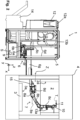
- FIG. 1 A cleaning system 1 is shown, with which mold segments 2, 3 of a Fig. 2 shown molding press 4 or vulcanization press for producing vehicle tires can be cleaned automatically.
- the cleaning system 1 has a frame 5 on which an adjustment unit 6 is arranged.
- a robot unit 7 consisting of three robot arms 8a, 8b, 8c is attached to the adjustment unit 6 via a robot base 8d.
- the individual robot arms 8a, 8b, 8c are connected to one another in an articulated manner so that the robot arms 8a, 8b, 8c can be pivoted against one another.
- the adjustment unit 6 and the robot unit 7 are controlled via control signals S from a schematically indicated control unit 9.
- a tool 10, which holds a nozzle 11, is arranged on a front robot arm 8c of the robot unit 7.
- the tool 10 or the nozzle 11 can be moved freely in space, including rotation, i.e. in all six degrees of freedom, via the robot arms 8a, 8b, 8c.
- the robot arms 8a, 8b, 8c are attached to a holder 15 of the adjustment unit 6 via a robot base 8d, on which the rear robot arm 8a is arranged so as to be rotatable about a rotation axis 8e.
- the holder 15 is aligned such that the robot unit 7 is in a wall-mounted position.
- the robot base 8d is attached in a plane running in the zy direction or the rear robot arm 8a protrudes essentially perpendicularly from the zy plane or the axis of rotation 8e, around which the rear robot arm 8a can rotate, protrudes horizontally or in the x direction from the bracket 15.
- This wall mounting position enables, as in Fig. 2 shown that the tool 10 with the nozzle 11 can be inserted laterally into or through a gap Z between the mold segments 2, 3 of the molding press 4. This enables lateral access for the cleaning process.
- the adjustment unit 6 serves to align the entire robot unit 7 in the x, y and z directions of a Cartesian coordinate system.
- the adjustment unit 6 has a first platform 6a as a base plate, at the corners of which drive motors 6b are arranged, which drive spindle nuts 6c.
- the spindle nuts 6c are in the z direction screwed onto spindles 6d which run along the axis of the frame 5. This allows the entire first platform 6a to be adjusted upwards or downwards in the z direction with synchronous control of the drive motors 6b.
- a rail-guided y-linear drive 6e is provided on the first platform 6a of the adjustment unit 6 for adjusting a second platform 6f in the y-direction and an x-linear drive 6g is provided on the second platform 6f for adjusting the robot unit 7 in the x-direction.
- the robot unit 7 mounted on the second platform 6f can thus be positioned in a predefined start position PS in the gap Z via a targeted control of the respective drives 6b, 6e, 6g of the adjustment unit 6.
- the start position PS is specified depending on the structure of the molding press 4 to be cleaned in order to be able to start the cleaning process on the respective molding press 4 in a controlled manner starting from this start position PS.
- the robot arms 8a, 8b, 8c assume a fixed position (positioning position) relative to one another in the start position PS in the gap Z.
- the robot unit 7 is used to move the nozzle 11 freely in all spatial directions of the Cartesian coordinate system in all six degrees of freedom in order to be able to align a dry ice jet T emerging from the nozzle 11 freely in space onto the mold segments 2, 3.
- the dry ice jet T can be used to remove rubber residues on the inner sides 2a, 3 of the mold segments 2, 3.
- the dry ice jet T is formed by dry ice pallets that are accelerated, for example, by compressed air.
- a dry ice container 12 is arranged on the frame 5, which can be filled from above via a filling opening 12a and which is connected to the nozzle 11 via a flexible hose 13.
- the hose 13 is in this case Fig. 2 in hose clamps 13a on the robot arms 8a, 8b, 8c and via hose channels 13b on the frame 5.
- the dry ice or dry ice pallets are fed from the Dry ice container 12 is pumped via hose 13 to nozzle 11 and from there is directed in jet form onto the inner sides 2a, 3a of the mold segments 2, 3, where it contributes to the removal of contaminants.
- the cleaning system 1 can first be manually positioned in a storage area A in front of the molding press 4 to be cleaned using a lifting truck 14.
- the robot unit 7 is then positioned at a specific starting position PS relative to the molding press 4 or to the individual mold segments 2, 3 to be cleaned using the adjustment unit 6.
- the wall mounting position of the robot unit 7 enables the robot unit 7 to be inserted into the gap Z.
- the molding press 4 is ready for the cleaning process, as shown in Fig. 2 shown, opened, ie the mold segments 2, 3 are moved apart so that the inner sides 2a, 3a of the mold segments 2, 3 are accessible to the nozzle 11 from the intermediate space Z and at the same time space is created for the movable robot arms 8a, 8b, 8c.
- the exact positioning of the robot unit 7 in the starting position PS relative to the mold segments 2, 3 is carried out with the aid of a camera 16 and a distance sensor 17, which according to this embodiment are arranged together with the nozzle 11 on the tool 10 (see Fig. 3a ). If the robot arms 8a, 8b, 8c are in the positioning position, the robot unit 7 can be moved by controlling the adjustment unit 6 in such a way that the camera 16 records a defined reference area RB on one of the mold segments 2, 3. In the camera image B of the camera 16, a camera-fixed structure K, for example a cross, is shown, which can be brought into a specific relative position to a reference object RO recorded by the camera 16 in the camera image B by controlling the adjustment unit 6.
- a camera-fixed structure K for example a cross
- the reference object RO is located in the reference area RB on the mold segments 2, 3 and can be formed, for example, by a component of the respective mold segment 2, 3 or by a structure subsequently applied to it.
- the camera 16 can thus be used to align the robot unit 7 in the xy plane.
- the distance sensor 17 is used for adjustment in the z-direction, whereby the distance sensor 17 indicates a distance D between the tool 10 and the mold segment 2, 3 in the reference area RB. This is set to a predetermined reference distance RD by controlling the adjustment unit 6.
- a defined position of the tool 10 and thus also of the nozzle 11 can be set in the start position PS relative to the mold segments 2, 3.
- This adjustment by the adjustment unit 6 with the aid of the camera 16 and the distance sensor 17 can be carried out manually by observing the camera image B and the distance D or can also be carried out automatically using corresponding algorithms that monitor the camera image B and the distance D.
- the positioning is preferably carried out separately for each individual mold segment 2, 3 of the molding press 4, so that an adjustment takes place before the cleaning process of each mold segment 2, 3. If the relative position of the two mold segments 2, 3 in the separated state is known, only one-time positioning is generally sufficient. After this, both mold segments 2, 3 of a molding press 4 can be cleaned one after the other.
- the control of the robot arms 8a, 8b, 8c is coordinated with the respective molding press 4 or its mold segments 2, 3, whereby the dimensions and the relative position of the inner sides 2a, 2b to the start position PS as well as to the tool 10 or the nozzle 11 are known.
- This allows automated cleaning to be carried out by successively moving over the entire inner sides 2a, 3a. Dismantling the mold segments 2, 3 or complex assembly and adjustment of the cleaning system 1 on the molding press 4 or the mold segments 2, 3 can thus be omitted. Only the described adjustment or positioning in the start position PS via the adjustment unit 6 is necessary.
- the process can also be monitored manually or fully automatically via the camera image B or the measured distance D.
Landscapes
- Engineering & Computer Science (AREA)
- Mechanical Engineering (AREA)
- Robotics (AREA)
- Physics & Mathematics (AREA)
- General Physics & Mathematics (AREA)
- Multimedia (AREA)
- Moulds For Moulding Plastics Or The Like (AREA)
- Cleaning In General (AREA)
Description
- Die Erfindung betrifft eine Reinigungsanlage zum Reinigen einer Formpresse sowie ein Reinigungsverfahren gemäß den unabhängigen Patentansprüchen. Formpressen zur Herstellung eines Fahrzeugreifens weisen herkömmlicherweise Formsegmente auf, die von Zeit zu Zeit von Gummirückständen zu befreien sind. Dazu sind Reinigungsanlagen bekannt, die mit einer Düse einen Trockeneisstrahl erzeugen, der auf Innenseiten der Formsegmente gerichtet wird. Dadurch können die Innenseiten von Gummirückständen befreit werden. Während des Reinigungsvorganges können die Formsegmente in der Formpresse montiert sein oder aber vorher umständlich demontiert werden. Die Düse kann zudem manuell über die Innenseiten verfahren werden oder aber automatisiert.
- Beispielhaft ist eine automatisiert betriebene Reinigungsanlage in
EP 1 074 344 B1 beschrieben. Demnach sind an einem Gestell eine Verstelleinheit sowie eine kardanisch aufgehängte Isolationshaube angeordnet. Die Verstelleinheit weist Linearantriebe und eine Schwenkeinrichtung auf, mit denen eine Düse zum Erzeugen des Trockeneisstrahls verstellt werden kann, um den Trockeneisstrahl über die Innenseiten der Formsegmente zu verfahren. Die Ausrichtung der Reinigungsanlage gegenüber der Formpresse bzw. den Formsegmenten erfolgt dadurch, dass die Isolationshaube während des Reinigungsverfahrens an der jeweiligen Formpresse bzw. den Formsegmenten über einen Klemm-/Rastmechanismus fixiert wird. Die Düse befindet sich dabei innerhalb eines Raumes, der durch die Formsegmente und die Isolationshaube begrenzt wird. - Aus den Druckschriften
WO 2016/175711 A2 ,WO 2016/105308 A1 ,CN 107 053 552 A ,EP 2 695 728 A1 ,WO 2019/115947 A1 ,EP 3 162 524 A1 undDE 198 30 397 A1 sind ebenfalls Reinigungsanlagen für bei der Reifenherstellung verwendete Formen bekannt. Insbesondere zeigtWO 2016/175711 A2 eine Reinigungsanlage gemäß dem Oberbegriff des Anspruchs 1 und ein Reiningungsverfahren gemäß dem Oberbegriff des Anspruchs 9. Die DruckschriftUS 2005/0159842 A1 offenbart ein Messsystem zum Erfassen einer dreidimensionalen Position eines zu messenden Objektes. - Nachteilig hierbei ist, dass die Reinigungsanlage manuell mit den Formsegmenten bzw. der Formpresse zu verklemmen bzw. zu verrasten ist, um den Reinigungsvorgang starten zu können. Dadurch wird der Arbeitsaufwand erhöht. Zudem ist die Isolationshaube individuell an jede Formpresse anzupassen, um das Verklemmen bzw. Verrasten zu ermöglichen. Damit ergibt sich ein teuer und schwer einzurichtender Aufbau. Ergänzend ist die Reinigungsanlage samt Isolationshaube groß und daher schwer zu handhaben. Außerdem ist die Düse über die Verstelleinheit nur sehr unflexibel, langsam und in begrenztem Maße verfahrbar. Dadurch wird eine vollständige Reinigung der Formsegmente sehr aufwändig. Weiterhin sind Reinigungsanlagen bekannt, bei denen die Düse an einem Werkzeug einer Robotereinheit mit mehreren Roboterarmen angeordnet ist, an denen der Schlauch entlanggeführt ist, wobei die Roboterarme derartig gelenkig miteinander verbunden und gegeneinander verschwenkbar sind, dass die Düse bei einer Ansteuerung der Robotereinheit frei im Raum bewegt werden kann. Nachteilig hierbei ist, dass bekannte Robotereinheiten über einen Roboterfuß am Boden montiert sind, d.h. sich in einer Bodenmontageposition befinden. Dadurch ist die Robotereinheit von unten an die einzelnen Formsegment heranzuführen. Da die Formsegmente einer Formpresse im geöffneten Zustand normalerweise übereinander liegen, ist das jeweilige Formsegment also zumindest teilweise zu demontieren, um den Zugang der Robotereinheit zu ermöglichen. Damit bleibt der Reinigungsprozess ebenfalls sehr aufwändig und wenig variabel.
- Aufgabe der Erfindung ist daher, eine Reinigungsanlage bereitzustellen, die universell einsetzbar und kompakt ist und mit der Formsegmente einer Formpresse mit wenig Aufwand in flexibler Weise gereinigt werden können. Aufgabe ist weiterhin, ein Reinigungsverfahren anzugeben.
- Diese Aufgabe wird durch eine Reinigungsanlage nach Anspruch 1 sowie ein Reinigungsverfahren nach dem weiteren unabhängigen Anspruch 9 gelöst. Die Unteransprüche geben bevorzugte Weiterbildung an.
- Demnach ist eine Reinigungsanlage zum Reinigen von Formsegmenten einer Formpresse vorgesehen, mit einem Gestell, einem Trockeneisbehälter und einer damit über einen flexiblen Schlauch verbundenen Düse zum Ausbilden eines Trockeneisstrahls, wobei die Düse mit einer Verstelleinheit wirkverbunden ist und die Düse durch eine elektrische Ansteuerung der Verstelleinheit relativ zum Gestell bewegt werden kann.
- Erfindungsgemäß ist dabei vorgesehen, dass die Düse an einem Werkzeug einer Robotereinheit mit mehreren Roboterarmen angeordnet ist, wobei die Roboterarme derartig gelenkig miteinander verbunden und gegeneinander verschwenkbar sind, dass die Düse bei einer Ansteuerung der Robotereinheit frei im Raum bewegt werden kann, wobei ein hinterer Roboterarm um eine Drehachse drehbar mit einem Roboterfuß der Robotereinheit verbunden ist, wobei die Robotereinheit über den Roboterfuß an einer Halterung der Verstelleinheit befestigt ist, wobei die Halterung derartig ausgerichtet ist, dass die Drehachse des hinteren Roboterarms im Wesentlichen horizontal in eine x-Richtung ausgerichtet ist, was einer Wandmontageposition der Robotereinheit entspricht, um der Verstelleinheit zu ermöglichen, die Robotereinheit in eine Start-Position zwischen den Formsegmenten der Formpresse zu bewegen.
- Dadurch kann die Düse vorteilhafterweise frei im Raum, d.h. in allen sechs Freiheitsgraden, bewegt werden, so dass sich der Trockeneisstrahl sehr flexibel auf die Formsegmente richten lässt, um die Innenseiten von Gummirückständen befreien zu können. Vorzugsweise sind dabei keine Verbindungselemente zwischen der Reinigungsanlage und der Formpresse bzw. den Formsegmenten vorgesehen, so dass die Reinigungsanlage universell einsetzbar ist. Die Reinigungsanlage kann also ausgehend von der Start-Position einen Reinigungsvorgang durchführen, ohne dabei mit der Formpresse verbunden zu sein, wodurch ein flexibler Einsatz nahezu unabhängig von der Formpresse ermöglicht wird. Die Formsegmente können dabei in Wandeinbaulage der Robotereinheit gereinigt werden, wodurch der Zugang verbessert wird, da die Robotereinheit durch einen Zwischenraum zwischen den Formsegmenten eingeführt und in der Start-Position positioniert werden kann und von da aus der Reinigungsvorgang erfolgen kann. Dadurch kann in einem Reinigungsverfahren die Start-Position derartig gewählt werden, dass die in der Start-Position positionierte Robotereinheit beide Formsegmente der Formpresse aus dem Zwischenraum mit der Düse erreichen kann. Dadurch wird der Reinigungsvorgang optimiert.
- Auch eine Isolationshaube wird nicht als Bestandteil der Reinigungsanlage benötigt, so dass die Reinigungsanlage kompakt aufgebaut ist. Dadurch ergibt sich eine gewisse Wendigkeit der Reinigungsanlage. Die Isolationshaube kann beispielweise Bestandteil der Formpresse selbst sein. Die Formpresse kann aber auch in einem schallisolierten Raum angeordnet sein, so dass eine zusätzliche Schallisolierung entfallen kann. Es ist lediglich dafür zu sorgen, dass die Robotereinheit, insbesondere das Werkzeug mit der Düse einen Zugang zu den Formsegmenten hat.
- Die erfindungsgemäße Reinigungsanlage umfasst eine Kamera zum Erfassen eines auf den Formsegmenten und/oder auf der Formpresse liegenden Referenz-Bereiches und eine Steuereinheit, die ausgebildet ist, die Verstelleinheit zum Einstellen der Start-Position der Robotereinheit derart anzusteuern, dass eine kamerafeste Struktur in einer festgelegten Relativposition zu einem auf den Formsegmenten und/oder auf der Formpresse in dem Referenz-Bereich angeordneten Referenz-Objekt ausgerichtet wird. Die erfindungsgemäße Reinigungsanlage umfasst zudem einen Abstands-Sensor zum Messen eines Abstandes zwischen dem Werkzeug und den Formsegmenten und/oder der Formpresse, wobei die Steuereinheit ausgebildet ist, die Verstelleinheit zum Einstellen der Start-Position der Robotereinheit derart elektrisch anzusteuern, dass der Abstand an einen Referenz-Abstand angenähert wird.
- Vorteilhafterweise ist über die Verstelleinheit eine einfache Ausrichtung der Reinigungsanlage relativ zu den Formsegmenten möglich. Dabei kann vorzugsweise vorgesehen sein, die Reinigungsanlage grob über einen Hubwagen in einem Abstellbereich vor der Formpresse auszurichten und anschließend über die Verstelleinheit eine Feinausrichtung der Robotereinheit durchzuführen, um die jeweilige Start-Position einzustellen, die beispielsweise in der Mitte der Formpresse liegen kann. Ausgehend davon kann dann der vorzugsweise vollautomatisierte Reinigungsvorgang erfolgen, der beispielweise durch eine elektrische Ansteuerung der Robotereinheit erfolgt, wobei dazu ein Rezept verwendet wird, das anhand der vorher ermittelten räumlichen Kontur der Formsegmente, insbesondere der Innenseiten, erstellt wird. Durch die elektrische Ansteuerung der Robotereinheit ist eine flexible Anpassung an unterschiedliche Formpressen und unterschiedlich konturierte Innenseiten möglich.
- Vorzugsweise ist weiterhin vorgesehen, dass die Verstelleinheit eine erste Plattform aufweist, an der Antriebsmotoren zum Verdrehen von Spindelmuttern befestigt sind, wobei die Spindelmuttern auf gestellfesten Spindeln laufen, so dass durch eine Ansteuerung der Antriebsmotoren ein Verstellen der ersten Plattform in eine z-Richtung ermöglicht ist. Damit kann eine einfache und genaue Verstellung der Robotereinheit in die z-Richtung bewirkt werden, so dass eine einfache und zuverlässige Feinjustierung relativ zur Formpresse möglich ist.
- Vorzugsweise ist weiterhin vorgesehen, dass auf der ersten Plattform ein x-Linearantrieb sowie ein y-Linearantrieb angeordnet sind, die mit der Robotereinheit zusammenwirken, zum Verstellen der Robotereinheit in die x-Richtung und/oder die y-Richtung. Damit können auch die anderen Richtungen in einfacher und zuverlässiger Weise eingestellt werden, um die Robotereinheit in die Start-Position zu bringen, aus der der Reinigungsvorgang gestartet wird.
- Vorzugsweise ist weiterhin vorgesehen, dass das Werkzeug mit der Düse an einem vorderen Roboterarm befestigt ist und an dem Werkzeug weiterhin eine Kamera zum Aufnehmen eines Referenz-Bereiches auf den Formsegmenten und/oder auf der Formpresse sowie
ein Abstands-Sensor zum Messen eines Abstandes zwischen dem Referenz-Bereich auf den Formsegmenten und/oder auf der Formpresse und dem Werkzeug angeordnet sind. - Dadurch lässt sich eine relative Position der Düse bzw. des Werkzeuges zum Formsegment in einfacher Weise kontrollieren bzw. einstellen. Darüber kann beispielsweise die Start-Position des Werkzeuges bzw. der Düse in einfacher Weise gefunden werden. Aber auch der Reinigungsvorgang lässt sich dadurch kontrollieren, indem z.B. fortlaufend der Abstand sowie der Referenz-Bereich beobachtet werden.
- Vorzugsweise ist weiterhin vorgesehen, dass die Reinigungsanlage weiterhin eine Steuereinheit aufweist, die ausgebildet ist,
- die Verstelleinheit anzusteuern zum Einstellen der Start-Position der Robotereinheit, und/oder
- die Robotereinheit anzusteuern zum freien Bewegen der Düse in allen sechs Freiheitsgraden.
- Dadurch lässt sich ein hoher Automatisierungsgrad erreichen, indem durch die Steuereinheit durch entsprechende Vorgaben, beispielsweise über Rezepte, das Verfahren der Düse vorzugsweise vollautomatisiert gesteuert wird, wobei die Bewegung beispielsweise in situ auch von der Steuereinheit überwacht werden kann, beispielsweise anhand des gemessenen Abstandes oder des Kamerabildes der Kamera.
- Aber auch die Verstelleinheit kann grundsätzlich vollautomatisiert betrieben werden, wobei die Steuereinheit dann ausgebildet ist, die Verstelleinheit in Abhängigkeit des von dem Abstands-Sensor gemessenen Abstandes und/oder des von der Kamera erfassten Referenz-Bereiches vollautomatisiert anzusteuern zum vollautomatisierten Positionieren der Robotereinheit in der Start-Position. Demnach kann auch bereits die Feinjustierung der Robotereinheit in die Start-Position vollautomatisiert erfolgen, wobei dazu beispielsweise ein entsprechender Algorithmus auf der Steuereinheit ausgeführt werden kann. Dies kann jedoch auch manuell erfolgen, indem Bedienpersonal das Kamerabild und/oder den gemessenen Abstand beobachten und entsprechend einstellen.
- In einem erfindungsgemäßen Reinigungsverfahren zum Reinigen einer Formpresse aus Formsegmenten mit einer erfindungsgemäßen Reinigungsanlage sind mindestens die folgenden Schritte vorgesehen:
- Abstellen der Reinigungsanlage in einem Abstellbereich vor der zu reinigenden Formpresse;
- Positionieren der Robotereinheit in einer Start-Position durch eine elektrische Ansteuerung der Verstelleinheit, wobei die Robotereinheit seitlich bzw. in x-Richtung in eine Start-Position in einen Zwischenraum zwischen den Formsegmenten der Formpresse gebracht wird;
- Starten des Reinigungsvorganges durch ein elektrisches Ansteuern der Robotereinheit.
- Dabei ist erfindungsgemäß vorgesehen, dass das Positionieren der Robotereinheit in der Start-Position durch Erfassen eines auf den Formsegmenten und/oder auf der Formpresse liegenden Referenz-Bereiches durch eine Kamera erfolgt, wobei die Verstelleinheit derartig elektrisch angesteuert wird, dass eine kamerafeste Struktur, beispielsweise ein Kreuz, in einer festgelegten Relativposition zu einem auf den Formsegmenten und/oder auf der Formpresse in dem Referenz-Bereich angeordneten Referenz-Objekt ausgerichtet wird, vorzugsweise zumindest teilweise in Überdeckung gebracht wird.
- Dies ermöglicht in einfacher Weise eine Ausrichtung des Werkzeuges bzw. der Düse relativ zum Formsegment in einer x-y-Ebene, wobei dieser Schritt automatisiert durch einen Algorithmus oder aber manuell durch Beobachten durch eine Bedienperson erfolgen kann.
- Ergänzend ist erfindungsgemäß vorgesehen, dass das Positionieren der Robotereinheit in der Start-Position durch Messen eines Abstandes zwischen dem Werkzeug und den Formsegmenten und/oder der Formpresse erfolgt,
wobei die Verstelleinheit derartig elektrisch angesteuert wird, dass der Abstand an einen Referenz-Abstand angenähert wird, vorzugsweise bis der Abstand dem Referenz-Abstand entspricht. - Zur Ausrichtung in der z-Richtung kann also eine einfache Abstands-Messung erfolgen, die ebenfalls automatisiert überwacht werden kann.
- Zum vollautomatisierten Einstellen der Start-Position über die Kamera und/oder den Abstand kann beispielsweise vorgesehen sein, dass das Bedienpersonal die Reinigungsanlage in den Abstellbereich in eine grobe Vorposition bringt, von der aus das Referenz-Objekt im Referenz-Bereich, beispielsweise das Kreuz und/oder eine Formmitte des unteren Formsegmentes oder des oberen Formsegmentes, im Kamerabild zu sehen ist. Dazu verwendet das Bedienpersonal z.B. eine manuelle Bedienfunktionen auf einem mobilen Bedienpult.
- Ein Algorithmus zur Bildverarbeitung in der Steuereinheit ermittelt anschließend anhand des Kamerabildes automatisch eine Referenz-Position des jeweiligen Referenz-Objektes. Die Steuereinheit positioniert die Robotereinheit anschließend derartig in der Start-Position, dass der Abstands-Sensor auf die zuvor ermittelte Referenz-Position zeigt bzw. die Düse bzw. das Werkzeug in einer definierten Relativ-Position zur Referenz-Position liegen. Damit ist der Steuereinheit die Position der Düse bzw. des Werkzeuges relativ zum jeweiligen Formsegment bekannt, so dass die Steuereinheit die notwendigen Verfahrwege zur Reinigung des jeweiligen Formsegmentes ableiten und das Rezept automatisch abfahren kann.
- Die Erfindung wird im Folgenden anhand von Figuren näher erläutert. Es zeigen:
- Fig. 1
- eine perspektive Ansicht der Reinigungsanlage;
- Fig. 2
- die Reinigungsanlage gemäß
Fig. 1 während eines Reinigungsvorganges; und - Fig. 3a, 3b
- Detailansichten zur Justierung einer Robotereinheit der Reinigungsanlage.
- In
Figur 1 ist eine Reinigungsanlage 1 dargestellt, mit der Formsegmente 2, 3 einer inFig. 2 dargestellten Formpresse 4 bzw. Vulkanisierungspresse zum Herstellen von Fahrzeugreifen automatisiert gereinigt werden können. Die Reinigungsanlage 1 weist ein Gestell 5 auf, an dem eine Verstelleinheit 6 angeordnet ist. Auf der Verstelleinheit 6 ist eine Robotereinheit 7 aus drei Roboterarmen 8a, 8b, 8c über einen Roboterfuß 8d befestigt. Die einzelnen Roboterarme 8a, 8b, 8c sind gelenkig miteinander verbunden, so dass ein Verschwenken der Roboterarme 8a, 8b, 8c gegeneinander ermöglicht wird. Gesteuert werden die Verstelleinheit 6 sowie die Robotereinheit 7 über Steuersignale S von einer schematisch angedeuteten Steuereinheit 9. - An einem vorderen Roboterarm 8c der Robotereinheit 7 ist ein Werkzeug 10, das eine Düse 11 hält, angeordnet. Über die Roboterarme 8a, 8b, 8c kann das Werkzeug 10 bzw. die Düse 11 frei im Raum, einschließlich einer Verdrehung, d.h. in allen sechs Freiheitsgraden, bewegt werden. Über einen Roboterfuß 8d, an dem der hintere Roboterarm 8a um eine Drehachse 8e drehbar angeordnet ist, sind die Roboterarme 8a, 8b, 8c an einer Halterung 15 der Verstelleinheit 6 befestigt. Die Halterung 15 ist dabei derartig ausgerichtet, dass die Robotereinheit 7 in einer Wandmontageposition liegt. Das bedeutet, dass der Roboterfuß 8d in einer in der z-y Richtung verlaufenden Ebene befestigt ist bzw. der hintere Roboterarm 8a im Wesentlichen senkrecht von der z-y-Ebene absteht bzw. die Drehachse 8e, um die der hintere Roboterarm 8a rotieren kann, horizontal bzw. in x-Richtung von der Halterung 15 absteht. Diese Wandmontageposition ermöglicht es, wie in
Fig. 2 dargestellt, dass das Werkzeug 10 mit der Düse 11 seitlich in bzw. durch einen Zwischenraum Z zwischen den Formsegmenten 2, 3 der Formpresse 4 eingeführt werden kann. Dadurch wird ein seitlicher Zugang für den Reinigungsvorgang ermöglicht. - Die Verstelleinheit 6 dient dazu, die gesamte Robotereinheit 7 in x-, y- und z-Richtung eines kartesischen Koordinatensystems auszurichten. Die Verstelleinheit 6 weist dazu gemäß dieser Ausführungsform eine erste Plattform 6a als Grundplatte auf, an deren Ecken Antriebsmotoren 6b angeordnet sind, die Spindelmuttern 6c antreiben. Die Spindelmuttern 6c sind auf in z-Richtung verlaufenden und an dem Gestell 5 befestigten Spindeln 6d aufgeschraubt. Dadurch kann die gesamte erste Plattform 6a bei einer synchronen Ansteuerung der Antriebsmotoren 6b in z-Richtung nach oben oder unten verstellt werden. Weiterhin ist auf der ersten Plattform 6a der Verstelleinheit 6 ein schienengeführter y-Linearantrieb 6e zur Verstellung einer zweiten Plattform 6f in die y-Richtung und auf der zweiten Plattform 6f ein x-Linearantrieb 6g zur Verstellung der Robotereinheit 7 in die x-Richtung vorgesehen.
- Die gemäß dieser Ausführungsform auf der zweiten Plattform 6f montierte Robotereinheit 7 kann dadurch über eine gezielte Ansteuerung der jeweiligen Antriebe 6b, 6e, 6g der Verstelleinheit 6 in einer vorab definierten Start-Position PS im Zwischenraum Z positioniert werden. Die Start-Position PS wird je nach Aufbau der zu reinigenden Formpresse 4 vorgegeben, um den Reinigungsvorgang an der jeweiligen Formpresse 4 ausgehend von dieser Start-Position PS kontrolliert starten zu können. Die Roboterarme 8a, 8b, 8c nehmen in der Start-Position PS im Zwischenraum Z eine festgelegte Stellung (Positionier-Stellung) zueinander ein.
- Die Robotereinheit 7 dient während des Reinigungsvorganges dazu, die Düse 11 frei in allen Raumrichtungen des kartesischen Koordinatensystems in allen sechs Freiheitsgraden zu bewegen, um einen aus der Düse 11 austretenden Trockeneisstrahl T frei im Raum auf die Formsegmente 2, 3 ausrichten zu können. Durch den Trockeneisstrahl T können Gummirückstände auf Innenseiten 2a, 3 der Formsegmente 2, 3 entfernt werden. Der Trockeneisstrahl T wird dabei durch Trockeneispallets ausgebildet, die beispielsweise durch Druckluft beschleunigt werden.
- Um einen derartigen Trockeneisstrahl T erzeugen zu können, ist auf dem Gestell 5 ein Trockeneisbehälter 12 angeordnet, der von oben über eine Einfüllöffnung 12a befüllt werden kann und der über einen flexiblen Schlauch 13 mit der Düse 11 verbunden ist. Der Schlauch 13 wird dabei gemäß
Fig. 2 in Schlauchschellen 13a an den Roboterarmen 8a, 8b, 8c sowie über Schlauchkanäle 13b am Gestell 5 geführt. Das Trockeneis bzw. die Trockeneispallets werden ausgehend vom Trockeneisbehälter 12 über den Schlauch 13 zur Düse 11 gepumpt und von dieser strahlförmig auf die Innenseiten 2a, 3a der Formsegmente 2, 3 geleitet, wo sie zum Ablösen der Verunreinigungen beitragen. - Zur Vorbereitung des Reinigungsvorganges kann die Reinigungsanlage 1 zunächst über einen Hubwagen 14 manuell in einem Abstellbereich A vor der zu reinigenden Formpresse 4 positioniert werden. Über die Verstelleinheit 6 wird die Robotereinheit 7 anschließend auf einer bestimmten Start-Position PS relativ zur Formpresse 4 bzw. zu den einzelnen zu reinigenden Formsegmenten 2, 3 positioniert. Die Wandmontageposition der Robotereinheit 7 ermöglicht dabei das Einführen der Robotereinheit 7 in den Zwischenraum Z. Die Formpresse 4 ist für den Reinigungsvorgang, wie in
Fig. 2 dargestellt, geöffnet, d.h. die Formsegmente 2, 3 sind auseinandergefahren, so dass die Innenseiten 2a, 3a der Formsegmente 2, 3 für die Düse 11 aus dem Zwischenraum Z zugänglich sind und gleichzeitig Platz für die beweglichen Roboterarme 8a, 8b, 8c geschaffen ist. - Das exakte Positionieren der Robotereinheit 7 in der Start-Position PS relativ zu den Formsegmenten 2, 3 erfolgt mithilfe einer Kamera 16 sowie eines Abstands-Sensor 17, die gemäß dieser Ausführungsform zusammen mit der Düse 11 an dem Werkzeug 10 angeordnet sind (s.
Fig. 3a ). Befinden sich die Roboterarme 8a, 8b, 8c in der Positionier-Stellung, so kann die Robotereinheit 7 durch eine Ansteuerung der Verstelleinheit 6 derartig verfahren werden, dass die Kamera 16 einen festgelegten Referenz-Bereich RB auf einem der Formsegmente 2, 3 aufnimmt. Im Kamerabild B der Kamera 16 ist eine kamerafeste Struktur K, beispielsweise ein Kreuz abgebildet, das durch eine Ansteuerung der Verstelleinheit 6 in eine bestimmte Relativposition zu einem von der Kamera 16 aufgenommenen Referenzobjekt RO im Kamerabild B zu bringen ist. Das Referenzobjekt RO befindet sich dabei im Referenz-Bereich RB auf den Formsegmenten 2, 3 und kann beispielsweise durch ein Bauteil des jeweiligen Formsegmentes 2, 3 oder durch eine nachträglich darauf aufgebrachte Struktur ausgebildet werden. Mit der Kamera 16 kann somit eine Ausrichtung der Robotereinheit 7 in der x-y-Ebene erreicht werden. - Über den Abstands-Sensor 17 erfolgt eine Justierung in der z-Richtung, wobei der Abstands-Sensor 17 dazu einen Abstand D zwischen dem Werkzeug 10 und dem Formsegment 2, 3 im Referenz-Bereich RB angibt. Dieser wird durch eine Ansteuerung der Verstelleinheit 6 auf einen vorgegebenen Referenz-Abstand RD eingestellt.
- Nach dieser Systematik kann in der Start-Position PS eine definierte Lage des Werkzeuges 10 und damit auch der Düse 11 relativ zu den Formsegmenten 2, 3 eingestellt werden. Diese Justierung durch die Verstelleinheit 6 mithilfe der Kamera 16 und dem Abstands-Sensor 17 kann hierbei manuell durch Beobachten des Kamerabildes B sowie des Abstandes D oder aber über entsprechende Algorithmen, die das Kamerabild B und den Abstand D überwachen, auch automatisiert erfolgen.
- Die Positionierung erfolgt dabei vorzugsweise für jedes einzelne Formsegment 2, 3 der Formpresse 4 separat, so dass vor dem Reinigungsvorgang jedes Formsegmentes 2, 3 eine Justierung stattfindet. Ist die relative Lage der beiden Formsegmente 2, 3 im auseinandergefahrenen Zustand bekannt, reicht aber grundsätzlich auch lediglich eine einmalige Positionierung. Nach dieser können beide Formsegmente 2, 3 einer Formpresse 4 nacheinander gereinigt werden.
- Für den Reinigungsvorgang erfolgt die Ansteuerung der Roboterarme 8a, 8b, 8c abgestimmt auf die jeweilige Formpresse 4 bzw. deren Formsegmente 2, 3, wobei die Abmessungen sowie die relative Lage der Innenseiten 2a, 2b zur Start-Position PS sowie auch zu dem Werkzeug 10 bzw. der Düse 11 bekannt sind. Dadurch kann durch sukzessives Abfahren der gesamten Innenseiten 2a, 3a eine automatisierte Reinigung erfolgen. Eine Demontage der Formsegmente 2, 3 oder ein aufwendiges Montieren und Justieren der Reinigungsanlage 1 an der Formpresse 4 oder den Formsegmenten 2, 3 kann dadurch entfallen. Es ist lediglich die beschriebene Justierung bzw. Positionierung in die Start-Position PS über die Verstelleinheit 6 nötig. Während des Reinigungsvorganges kann zudem über das Kamerabild B bzw. den gemessenen Abstand D der Prozess manuell oder vollautomatisiert überwacht werden.
-
- 1
- Reinigungsanlage
- 2, 3
- Formsegmente
- 2a, 3a
- Innenseiten der Formsegmente
- 4
- Formpresse
- 5
- Gestell
- 6
- Verstelleinheit
- 6a
- erste Plattform
- 6b
- Antriebsmotor
- 6c
- Spindelmutter
- 6d
- Spindel
- 6e
- y-Linearantrieb
- 6f
- zweite Plattform
- 6g
- x-Linearantrieb
- 7
- Robotereinheit
- 8a, 8b, 8c
- Roboterarme
- 8d
- Roboterfuß
- 8e
- Drehachse
- 9
- Steuereinheit
- 10
- Werkzeug
- 11
- Düse
- 12
- Trockeneisbehälter
- 12a
- Einfüllöffnung
- 13
- Schlauch
- 13a
- Schlauchschelle
- 13b
- Schlauchkanal
- 14
- Hubwagen
- 15
- Halterung
- 16
- Kamera
- 17
- Abstands-Sensor
- A
- Abstellbereich
- B
- Kamerabild
- D
- Abstand
- K
- kamerafeste Struktur
- PS
- Start-Position
- RB
- Referenz-Bereich
- RD
- Referenz-Abstand
- RO
- Referenz-Objekt
- S
- Steuersignal
- T
- Trockeneisstrahl
- Z
- Zwischenraum
Claims (13)
- Reinigungsanlage (1) zum Reinigen von Formsegmenten (2, 3) einer Formpresse (4) mit einem Gestell (5), einem Trockeneisbehälter (12) und einer damit über einen flexiblen Schlauch (13) verbundenen Düse (11) zum Ausbilden eines Trockeneisstrahls (T), wobei die Düse (11) mit einer Verstelleinheit (6) wirkverbunden ist, wobei die Düse (11) durch eine elektrische Ansteuerung der Verstelleinheit (6) relativ zum Gestell (5) bewegt werden kann,wobei die Düse (11) an einem Werkzeug (10) einer Robotereinheit (7) mit mehreren Roboterarmen (8a, 8b, 8c) angeordnet ist, wobei die Roboterarme (8a, 8b, 8c) derartig gelenkig miteinander verbunden und gegeneinander verschwenkbar sind, dass die Düse (11) bei einer Ansteuerung der Robotereinheit (7) frei im Raum bewegt werden kann,wobei ein hinterer Roboterarm (8a) um eine Drehachse (8e) drehbar mit einem Roboterfuß (8d) der Robotereinheit (7) verbunden ist, wobei die Robotereinheit (7) über den Roboterfuß (8d) an einer Halterung (15) der Verstelleinheit (6) befestigt ist,wobei die Halterung (15) derartig ausgerichtet ist, dass die Drehachse (8e) des hinteren Roboterarms (8a) im Wesentlichen horizontal in eine x-Richtung ausgerichtet ist, um der Verstelleinheit (6) zu ermöglichen, die Robotereinheit (7) in eine Start-Position (PS) zwischen den Formsegmenten (2, 3) der Formpresse (4) zu bewegen,gekennzeichnet durcheine Kamera zum Erfassen eines auf den Formsegmenten (2, 3) und/oder auf der Formpresse (4) liegenden Referenz-Bereiches (RB), undeine Steuereinheit (9), die ausgebildet ist, die Verstelleinheit (6) zum Einstellen der Start-Position (PS) der Robotereinheit (7) derart anzusteuern, dass eine kamerafeste Struktur (K) in einer festgelegten Relativposition zu einem auf den Formsegmenten (2, 3) und/oder auf der Formpresse (4) in dem Referenz-Bereich (RB) angeordneten Referenz-Objekt (RO) ausgerichtet wird, undeinen Abstands-Sensor (17) zum Messen eines Abstandes (D) zwischen dem Werkzeug (10) und den Formsegmenten (2, 3) und/oder der Formpresse (4), wobei die Steuereinheit (9) ausgebildet ist, die Verstelleinheit (6) zum Einstellen der Start-Position (PS) der Robotereinheit (7) derart elektrisch anzusteuern, dass der Abstand (D) an einen Referenz-Abstand (RD) angenähert wird.
- Reinigungsanlage (1) nach Anspruch 1,
dadurch gekennzeichnet, dass
die Verstelleinheit (6) eine erste Plattform (6a) aufweist, an der Antriebsmotoren (6b) zum Verdrehen von Spindelmuttern (6c) befestigt sind, wobei die Spindelmuttern (6c) auf gestellfesten Spindeln (6d) laufen, so dass durch eine Ansteuerung der Antriebsmotoren (6b) ein Verstellen der ersten Plattform (6a) in eine z-Richtung ermöglicht ist. - Reinigungsanlage (1) nach Anspruch 2,
dadurch gekennzeichnet, dass
auf der ersten Plattform (6a) ein x-Linearantrieb (6e) sowie ein y-Linearantrieb (6g) angeordnet sind, die mit der Robotereinheit (7) zusammenwirken, zum Verstellen der Robotereinheit (7) in die x- Richtung und/oder die y-Richtung. - Reinigungsanlage (1) nach einem der vorhergehenden Ansprüche,
dadurch gekennzeichnet, dassdas Werkzeug (10) mit der Düse (11) an einem vorderen Roboterarm (8c) befestigt ist und an dem Werkzeug (10) weiterhindie Kamera (16) zum Aufnehmen des Referenz-Bereiches (RB) auf den Formsegmenten (2, 3) und/oder auf der Formpresse (4) sowie der Abstands-Sensor (17) zum Messen des Abstandes (D) zwischen dem Referenz-Bereich (RB) auf den Formsegmenten (2, 3) und/oder auf der Formpresse (4) und dem Werkzeug (10) angeordnet sind. - Reinigungsanlage (1) nach einem der vorhergehenden Ansprüche,
dadurch gekennzeichnet, dass
die Steuereinheit (9) ausgebildet ist, die Robotereinheit (7) zum freien Bewegen der Düse (11) in allen sechs Freiheitsgraden anzusteuern. - Reinigungsanlage (1) nach Anspruch 5,
dadurch gekennzeichnet, dass
die Steuereinheit (9) ausgebildet ist, die Verstelleinheit (6) und/oder die Robotereinheit (7) vollautomatisiert anzusteuern. - Reinigungsanlage (1) nach Anspruch 6,
dadurch gekennzeichnet, dass
die Steuereinheit (9) ausgebildet ist, die Verstelleinheit (6) in Abhängigkeit des von dem Abstands-Sensor (17) gemessenen Abstandes (D) und/oder des von der Kamera (16) erfassten Referenz-Bereiches (RB) vollautomatisiert anzusteuern zum vollautomatisierten Positionieren der Robotereinheit (7) in der Start-Position (PS). - Reinigungsanlage (1) nach einem der vorhergehenden Ansprüche,
dadurch gekennzeichnet, dass
die Reinigungsanlage (1) auf einem Hubwagen (14) angeordnet ist zum Positionieren der Reinigungsanlage in einem Abstellbereich (A). - Reinigungsverfahren zum Reinigen einer Formpresse (4) aus Formsegmenten (2, 3) mit einer Reinigungsanlage (1) nach einem der vorhergehenden Ansprüche, mit mindestens den folgenden Schritten:- Abstellen der Reinigungsanlage (1) in einem Abstellbereich (A) vor der zu reinigenden Formpresse (4);- Positionieren der Robotereinheit (7) in einer Start-Position (PS) durch eine elektrische Ansteuerung der Verstelleinheit (6), wobei die Robotereinheit (7) seitlich in eine Start-Position (PS) in einen Zwischenraum (Z) zwischen den Formsegmenten (2, 3) der Formpresse (4) gebracht wird;- Starten des Reinigungsvorganges durch ein elektrisches Ansteuern der Robotereinheit (7);dadurch gekennzeichnet, dass das Positionieren der Robotereinheit (7) in der Start-Position (PS) durch Erfassen eines auf den Formsegmenten (2, 3) und/oder auf der Formpresse (4) liegenden Referenz-Bereiches (RB) durch eine Kamera (16) erfolgt,wobei die Verstelleinheit (6) derartig elektrisch angesteuert wird, dass eine kamerafeste Struktur (K) in einer festgelegten Relativposition zu einem auf den Formsegmenten (2, 3) und/oder auf der Formpresse (4) in dem Referenz-Bereich (RB) angeordneten Referenz-Objekt (RO) ausgerichtet wird, unddas Positionieren der Robotereinheit (7) in der Start-Position (PS) durch Messen eines Abstandes (D) zwischen dem Werkzeug (10) und den Formsegmenten (2, 3) und/oder der Formpresse (4) erfolgt,wobei die Verstelleinheit (6) derartig elektrisch angesteuert wird, dass der Abstand (D) an einen Referenz-Abstand (RD) angenähert wird.
- Reinigungsverfahren nach Anspruch 9,
dadurch gekennzeichnet, dass die Verstelleinheit (6) derartig elektrisch angesteuert wird, dass die kamerafeste Struktur (K) in zumindest teilweise Überdeckung mit dem auf den Formsegmenten (2, 3) und/oder auf der Formpresse (4) in dem Referenz-Bereich (RB) angeordneten Referenz-Objekt (RO) gebracht wird. - Reinigungsverfahren nach Anspruch 9 oder 10,
dadurch gekennzeichnet, dass
die Verstelleinheit (6) derartig elektrisch angesteuert wird, dass der Abstand (D) an einen Referenz-Abstand (RD) angenähert wird, bis der Abstand (D) dem Referenz-Abstand (RD) entspricht. - Reinigungsverfahren nach einem der Ansprüche 9 bis 11,
dadurch gekennzeichnet, dass
das elektrische Ansteuern der Verstelleinheit (6) und/oder der Robotereinheit (7) vollautomatisiert erfolgt, wobei die Robotereinheit (7) zum vollautomatisierten Einstellen der Start-Position (PS) über die Kamera (16) und/oder den Abstand (D) zunächst in eine Vorposition gebracht wird, wobei das Referenz-Objekt (RO) in der Vorposition im Referenz-Bereich (RB) im Kamerabild (B) enthalten ist, und anschließend durch Bildverarbeitung anhand des Kamerabildes (B) eine Referenz-Position des jeweiligen Referenz-Objektes (RO) ermittelt wird und die Robotereinheit (7) anschließend in Abhängigkeit der ermittelten Referenz-Position automatisiert in eine derartige Start-Position (PS) gebracht wird, dass in der Start-Position (PS) der Abstand (D) zu der zuvor ermittelten Referenz-Position ermittelt werden kann und die Düse (11) in einer festgelegten Relativposition zum Referenz-Objekt (RO) liegt. - Reinigungsverfahren nach einem der Ansprüche 9 bis 12,
dadurch gekennzeichnet, dass
die Start-Position (PS) derartig gewählt wird, dass die in der Start-Position (PS) positionierte Robotereinheit (7) beide Formsegmente (2, 3) der Formpresse (4) mit der Düse (11) erreichen kann.
Applications Claiming Priority (1)
| Application Number | Priority Date | Filing Date | Title |
|---|---|---|---|
| DE102020200467.6A DE102020200467A1 (de) | 2020-01-16 | 2020-01-16 | Reinigungsanlage sowie Reinigungsverfahren |
Publications (2)
| Publication Number | Publication Date |
|---|---|
| EP3851247A1 EP3851247A1 (de) | 2021-07-21 |
| EP3851247B1 true EP3851247B1 (de) | 2024-10-16 |
Family
ID=73646121
Family Applications (1)
| Application Number | Title | Priority Date | Filing Date |
|---|---|---|---|
| EP20210540.9A Active EP3851247B1 (de) | 2020-01-16 | 2020-11-30 | Reinigungsanlage sowie reinigungsverfahren |
Country Status (2)
| Country | Link |
|---|---|
| EP (1) | EP3851247B1 (de) |
| DE (1) | DE102020200467A1 (de) |
Citations (2)
| Publication number | Priority date | Publication date | Assignee | Title |
|---|---|---|---|---|
| US20050159842A1 (en) * | 2004-01-16 | 2005-07-21 | Fanuc Ltd | Measuring system |
| EP3162524A1 (de) * | 2014-06-26 | 2017-05-03 | The Yokohama Rubber Co., Ltd. | Reinigungssystem für gussform |
Family Cites Families (7)
| Publication number | Priority date | Publication date | Assignee | Title |
|---|---|---|---|---|
| DE19830397A1 (de) * | 1998-07-08 | 2000-01-20 | Diw Instandhaltung Gmbh | Vorrichtung und Verfahren zum Reinigen von Vulkanisierformen |
| DE19936698C1 (de) | 1999-08-04 | 2000-12-21 | Continental Ag | Vorrichtung zur Reinigung von Vulkanisationsformen |
| DE102012107225A1 (de) * | 2012-08-07 | 2014-02-13 | enotech AG | Vorrichtung und Verfahren zum Reinigen von Vulkanisationsformen |
| PL3319770T3 (pl) * | 2014-12-25 | 2020-01-31 | Lang Yuzer Otomotiv Yan Sanayi Ve Ticaret Anonim Sirketi | Urządzenie czyszczące ściankę boczną formy do wulkanizacji opon |
| WO2016175711A2 (en) * | 2015-04-30 | 2016-11-03 | Keymical 2 Rsm S.R.L. | Automatic apparatus for in-line cleaning of moulds for tyres |
| CN107053552A (zh) * | 2017-04-21 | 2017-08-18 | 烟台拓伟智能科技股份有限公司 | 硫化机模具自动清洗系统 |
| EP3723970B1 (de) * | 2017-12-14 | 2024-12-11 | Compagnie Generale Des Etablissements Michelin | Verfahren und vorrichtung zum reinigen einer vulkanisierungsform |
-
2020
- 2020-01-16 DE DE102020200467.6A patent/DE102020200467A1/de active Pending
- 2020-11-30 EP EP20210540.9A patent/EP3851247B1/de active Active
Patent Citations (2)
| Publication number | Priority date | Publication date | Assignee | Title |
|---|---|---|---|---|
| US20050159842A1 (en) * | 2004-01-16 | 2005-07-21 | Fanuc Ltd | Measuring system |
| EP3162524A1 (de) * | 2014-06-26 | 2017-05-03 | The Yokohama Rubber Co., Ltd. | Reinigungssystem für gussform |
Also Published As
| Publication number | Publication date |
|---|---|
| DE102020200467A1 (de) | 2021-07-22 |
| EP3851247A1 (de) | 2021-07-21 |
Similar Documents
| Publication | Publication Date | Title |
|---|---|---|
| DE60223864T2 (de) | Tranportvorrichtung für Kraftfahrzeugkarosserien und ein Verfahren dazu | |
| DE102004033640B4 (de) | Farbauftragssystem | |
| EP1223002B1 (de) | Halteeinrichtung zum Halten von grossformatigen Bauteilen | |
| EP2695728B1 (de) | Vorrichtung zum Reinigen von Vulkanisationsformen | |
| DE102017124424A1 (de) | Hubeinrichtung für einen Bauzylinder in einer Maschine, Maschine zur Herstellung von dreidimensionalen Bauteilen mit einer Hubeinrichtung sowie Verfahren zur Ansteuerung der Hubeinrichtung | |
| DE19531520A1 (de) | Vorrichtung zum Positionieren und Fixieren von Körpern | |
| EP3448623B1 (de) | Montagevorrichtung, verfahren zur steuerung der montagevorrichtung und verfahren zum herstellen in einer montagevorrichtung | |
| EP3451096B1 (de) | Bearbeitungssystem mit einer auf einem fahrzeug angeordneten aufnahmeeinheit für mindestens ein bauteil und verfahren zum bearbeiten mindestens eines bauteils | |
| DE3303588A1 (de) | Einrichtung zur automatischen betaetigung von bedienungshebeln eines kraftfahrzeugs auf einem rollenpruefstand | |
| WO2000002709A1 (de) | Vorrichtung zum reinigen einer vulkanisierform mittels trockeneis | |
| DE4311647C2 (de) | Vorrichtung zur Nachbildung einer Fahrzeugkarosserie | |
| WO2008080384A2 (de) | Verfahren zum ein- oder ausbau von bauteilen an bzw. von fahrzeugkomponenten | |
| DE102017001334A1 (de) | Anordnung zum Eindrehen einer Mehrzahl von Schrauben | |
| DE10164159A1 (de) | System zur automatischen Positionierung eines Armaturenbretts für ein Fahrzeug sowie Positionsierungsverfahren dafür | |
| EP3129192A1 (de) | Vorrichtung und verfahren zum automatisierten bearbeiten von werkstücken | |
| EP3851247A1 (de) | Reinigungsanlage sowie reinigungsverfahren | |
| DE102018000500A1 (de) | Roboteranordnung | |
| DE102009009677A1 (de) | Einbauvorrichtung zum Einbau eines Cockpitmoduls | |
| DE2529343A1 (de) | Verfahren und vorrichtung zum montieren und demontieren von kraftfahrzeugreifen, insbesondere kraftfahrzeugreifen fuer lastkraftwagen | |
| EP1699680B1 (de) | Automatische schraubereinrichtung und fügeverfahren | |
| DE102021108015B3 (de) | Messplatte für ein Messsystem | |
| EP3717187A1 (de) | Aufnahmevorrichtung für die fixierung polymerer kfz-bauteile | |
| DE102022127184A1 (de) | Produktionssystem mit mehreren Produktionszellen | |
| DE102010024190A1 (de) | Verfahren zur Montage eines Anbauteils an einer Karosserie eines Kraftwagens | |
| DE102012222383A1 (de) | Handhabe, Transportvorrichtung und Einbauverfahren für ein Fahrzeugteil |
Legal Events
| Date | Code | Title | Description |
|---|---|---|---|
| PUAI | Public reference made under article 153(3) epc to a published international application that has entered the european phase |
Free format text: ORIGINAL CODE: 0009012 |
|
| STAA | Information on the status of an ep patent application or granted ep patent |
Free format text: STATUS: THE APPLICATION HAS BEEN PUBLISHED |
|
| AK | Designated contracting states |
Kind code of ref document: A1 Designated state(s): AL AT BE BG CH CY CZ DE DK EE ES FI FR GB GR HR HU IE IS IT LI LT LU LV MC MK MT NL NO PL PT RO RS SE SI SK SM TR |
|
| RIN1 | Information on inventor provided before grant (corrected) |
Inventor name: SCHLIESSAUF, JENS Inventor name: MAYER, STEFAN - C/O CONTINENTAL AG Inventor name: KREMER, MAXIMILIAN - C/O CONTINENTAL AG Inventor name: SVEBIS, KAREL - C/O CONTINENTAL AG Inventor name: GUEMMER, OLIVER - C/O CONTINENTAL AG Inventor name: BREMER, JAN - C/O CONTINENTAL AG |
|
| STAA | Information on the status of an ep patent application or granted ep patent |
Free format text: STATUS: REQUEST FOR EXAMINATION WAS MADE |
|
| 17P | Request for examination filed |
Effective date: 20220121 |
|
| RBV | Designated contracting states (corrected) |
Designated state(s): AL AT BE BG CH CY CZ DE DK EE ES FI FR GB GR HR HU IE IS IT LI LT LU LV MC MK MT NL NO PL PT RO RS SE SI SK SM TR |
|
| STAA | Information on the status of an ep patent application or granted ep patent |
Free format text: STATUS: EXAMINATION IS IN PROGRESS |
|
| 17Q | First examination report despatched |
Effective date: 20231023 |
|
| RAP3 | Party data changed (applicant data changed or rights of an application transferred) |
Owner name: CONTINENTAL REIFEN DEUTSCHLAND GMBH |
|
| RIC1 | Information provided on ipc code assigned before grant |
Ipc: G01B 11/02 20060101ALI20240514BHEP Ipc: G01B 11/00 20060101ALI20240514BHEP Ipc: B25J 21/00 20060101ALI20240514BHEP Ipc: B29D 30/06 20060101ALI20240514BHEP Ipc: B25J 19/02 20060101ALI20240514BHEP Ipc: B25J 11/00 20060101ALI20240514BHEP Ipc: B29C 33/72 20060101ALI20240514BHEP Ipc: B24C 3/06 20060101ALI20240514BHEP Ipc: B24C 3/32 20060101ALI20240514BHEP Ipc: B24C 1/00 20060101AFI20240514BHEP |
|
| GRAP | Despatch of communication of intention to grant a patent |
Free format text: ORIGINAL CODE: EPIDOSNIGR1 |
|
| STAA | Information on the status of an ep patent application or granted ep patent |
Free format text: STATUS: GRANT OF PATENT IS INTENDED |
|
| INTG | Intention to grant announced |
Effective date: 20240705 |
|
| GRAS | Grant fee paid |
Free format text: ORIGINAL CODE: EPIDOSNIGR3 |
|
| GRAA | (expected) grant |
Free format text: ORIGINAL CODE: 0009210 |
|
| STAA | Information on the status of an ep patent application or granted ep patent |
Free format text: STATUS: THE PATENT HAS BEEN GRANTED |
|
| P01 | Opt-out of the competence of the unified patent court (upc) registered |
Free format text: CASE NUMBER: APP_47209/2024 Effective date: 20240814 |
|
| AK | Designated contracting states |
Kind code of ref document: B1 Designated state(s): AL AT BE BG CH CY CZ DE DK EE ES FI FR GB GR HR HU IE IS IT LI LT LU LV MC MK MT NL NO PL PT RO RS SE SI SK SM TR |
|
| REG | Reference to a national code |
Ref country code: GB Ref legal event code: FG4D Free format text: NOT ENGLISH |
|
| REG | Reference to a national code |
Ref country code: CH Ref legal event code: EP |
|
| REG | Reference to a national code |
Ref country code: IE Ref legal event code: FG4D Free format text: LANGUAGE OF EP DOCUMENT: GERMAN |
|
| REG | Reference to a national code |
Ref country code: DE Ref legal event code: R096 Ref document number: 502020009489 Country of ref document: DE |
|
| REG | Reference to a national code |
Ref country code: LT Ref legal event code: MG9D |
|
| REG | Reference to a national code |
Ref country code: NL Ref legal event code: MP Effective date: 20241016 |
|
| PG25 | Lapsed in a contracting state [announced via postgrant information from national office to epo] |
Ref country code: NL Free format text: LAPSE BECAUSE OF FAILURE TO SUBMIT A TRANSLATION OF THE DESCRIPTION OR TO PAY THE FEE WITHIN THE PRESCRIBED TIME-LIMIT Effective date: 20241016 |
|
| PG25 | Lapsed in a contracting state [announced via postgrant information from national office to epo] |
Ref country code: NL Free format text: LAPSE BECAUSE OF FAILURE TO SUBMIT A TRANSLATION OF THE DESCRIPTION OR TO PAY THE FEE WITHIN THE PRESCRIBED TIME-LIMIT Effective date: 20241016 |
|
| PG25 | Lapsed in a contracting state [announced via postgrant information from national office to epo] |
Ref country code: HR Free format text: LAPSE BECAUSE OF FAILURE TO SUBMIT A TRANSLATION OF THE DESCRIPTION OR TO PAY THE FEE WITHIN THE PRESCRIBED TIME-LIMIT Effective date: 20241016 Ref country code: PT Free format text: LAPSE BECAUSE OF FAILURE TO SUBMIT A TRANSLATION OF THE DESCRIPTION OR TO PAY THE FEE WITHIN THE PRESCRIBED TIME-LIMIT Effective date: 20250217 Ref country code: IS Free format text: LAPSE BECAUSE OF FAILURE TO SUBMIT A TRANSLATION OF THE DESCRIPTION OR TO PAY THE FEE WITHIN THE PRESCRIBED TIME-LIMIT Effective date: 20250216 |
|
| PG25 | Lapsed in a contracting state [announced via postgrant information from national office to epo] |
Ref country code: FI Free format text: LAPSE BECAUSE OF FAILURE TO SUBMIT A TRANSLATION OF THE DESCRIPTION OR TO PAY THE FEE WITHIN THE PRESCRIBED TIME-LIMIT Effective date: 20241016 |
|
| PG25 | Lapsed in a contracting state [announced via postgrant information from national office to epo] |
Ref country code: BG Free format text: LAPSE BECAUSE OF FAILURE TO SUBMIT A TRANSLATION OF THE DESCRIPTION OR TO PAY THE FEE WITHIN THE PRESCRIBED TIME-LIMIT Effective date: 20241016 |
|
| PG25 | Lapsed in a contracting state [announced via postgrant information from national office to epo] |
Ref country code: ES Free format text: LAPSE BECAUSE OF FAILURE TO SUBMIT A TRANSLATION OF THE DESCRIPTION OR TO PAY THE FEE WITHIN THE PRESCRIBED TIME-LIMIT Effective date: 20241016 |
|
| PG25 | Lapsed in a contracting state [announced via postgrant information from national office to epo] |
Ref country code: NO Free format text: LAPSE BECAUSE OF FAILURE TO SUBMIT A TRANSLATION OF THE DESCRIPTION OR TO PAY THE FEE WITHIN THE PRESCRIBED TIME-LIMIT Effective date: 20250116 |
|
| PG25 | Lapsed in a contracting state [announced via postgrant information from national office to epo] |
Ref country code: LV Free format text: LAPSE BECAUSE OF FAILURE TO SUBMIT A TRANSLATION OF THE DESCRIPTION OR TO PAY THE FEE WITHIN THE PRESCRIBED TIME-LIMIT Effective date: 20241016 Ref country code: GR Free format text: LAPSE BECAUSE OF FAILURE TO SUBMIT A TRANSLATION OF THE DESCRIPTION OR TO PAY THE FEE WITHIN THE PRESCRIBED TIME-LIMIT Effective date: 20250117 |
|
| PG25 | Lapsed in a contracting state [announced via postgrant information from national office to epo] |
Ref country code: PL Free format text: LAPSE BECAUSE OF FAILURE TO SUBMIT A TRANSLATION OF THE DESCRIPTION OR TO PAY THE FEE WITHIN THE PRESCRIBED TIME-LIMIT Effective date: 20241016 |
|
| PG25 | Lapsed in a contracting state [announced via postgrant information from national office to epo] |
Ref country code: RS Free format text: LAPSE BECAUSE OF FAILURE TO SUBMIT A TRANSLATION OF THE DESCRIPTION OR TO PAY THE FEE WITHIN THE PRESCRIBED TIME-LIMIT Effective date: 20250116 |
|
| REG | Reference to a national code |
Ref country code: CH Ref legal event code: PL |
|
| PG25 | Lapsed in a contracting state [announced via postgrant information from national office to epo] |
Ref country code: SM Free format text: LAPSE BECAUSE OF FAILURE TO SUBMIT A TRANSLATION OF THE DESCRIPTION OR TO PAY THE FEE WITHIN THE PRESCRIBED TIME-LIMIT Effective date: 20241016 |
|
| PG25 | Lapsed in a contracting state [announced via postgrant information from national office to epo] |
Ref country code: MC Free format text: LAPSE BECAUSE OF FAILURE TO SUBMIT A TRANSLATION OF THE DESCRIPTION OR TO PAY THE FEE WITHIN THE PRESCRIBED TIME-LIMIT Effective date: 20241016 |
|
| PG25 | Lapsed in a contracting state [announced via postgrant information from national office to epo] |
Ref country code: DK Free format text: LAPSE BECAUSE OF FAILURE TO SUBMIT A TRANSLATION OF THE DESCRIPTION OR TO PAY THE FEE WITHIN THE PRESCRIBED TIME-LIMIT Effective date: 20241016 |
|
| PG25 | Lapsed in a contracting state [announced via postgrant information from national office to epo] |
Ref country code: LU Free format text: LAPSE BECAUSE OF NON-PAYMENT OF DUE FEES Effective date: 20241130 |
|
| REG | Reference to a national code |
Ref country code: CH Ref legal event code: PL |
|
| REG | Reference to a national code |
Ref country code: DE Ref legal event code: R097 Ref document number: 502020009489 Country of ref document: DE |
|
| PG25 | Lapsed in a contracting state [announced via postgrant information from national office to epo] |
Ref country code: EE Free format text: LAPSE BECAUSE OF FAILURE TO SUBMIT A TRANSLATION OF THE DESCRIPTION OR TO PAY THE FEE WITHIN THE PRESCRIBED TIME-LIMIT Effective date: 20241016 |
|
| PG25 | Lapsed in a contracting state [announced via postgrant information from national office to epo] |
Ref country code: CH Free format text: LAPSE BECAUSE OF NON-PAYMENT OF DUE FEES Effective date: 20241130 |
|
| PG25 | Lapsed in a contracting state [announced via postgrant information from national office to epo] |
Ref country code: RO Free format text: LAPSE BECAUSE OF FAILURE TO SUBMIT A TRANSLATION OF THE DESCRIPTION OR TO PAY THE FEE WITHIN THE PRESCRIBED TIME-LIMIT Effective date: 20241016 |
|
| PG25 | Lapsed in a contracting state [announced via postgrant information from national office to epo] |
Ref country code: SK Free format text: LAPSE BECAUSE OF FAILURE TO SUBMIT A TRANSLATION OF THE DESCRIPTION OR TO PAY THE FEE WITHIN THE PRESCRIBED TIME-LIMIT Effective date: 20241016 |
|
| PG25 | Lapsed in a contracting state [announced via postgrant information from national office to epo] |
Ref country code: IT Free format text: LAPSE BECAUSE OF FAILURE TO SUBMIT A TRANSLATION OF THE DESCRIPTION OR TO PAY THE FEE WITHIN THE PRESCRIBED TIME-LIMIT Effective date: 20241016 |
|
| PLBE | No opposition filed within time limit |
Free format text: ORIGINAL CODE: 0009261 |
|
| STAA | Information on the status of an ep patent application or granted ep patent |
Free format text: STATUS: NO OPPOSITION FILED WITHIN TIME LIMIT |
|
| REG | Reference to a national code |
Ref country code: BE Ref legal event code: MM Effective date: 20241130 |
|
| PG25 | Lapsed in a contracting state [announced via postgrant information from national office to epo] |
Ref country code: SE Free format text: LAPSE BECAUSE OF FAILURE TO SUBMIT A TRANSLATION OF THE DESCRIPTION OR TO PAY THE FEE WITHIN THE PRESCRIBED TIME-LIMIT Effective date: 20241016 |
|
| 26N | No opposition filed |
Effective date: 20250717 |
|
| GBPC | Gb: european patent ceased through non-payment of renewal fee |
Effective date: 20250116 |
|
| PG25 | Lapsed in a contracting state [announced via postgrant information from national office to epo] |
Ref country code: GB Free format text: LAPSE BECAUSE OF NON-PAYMENT OF DUE FEES Effective date: 20250116 Ref country code: BE Free format text: LAPSE BECAUSE OF NON-PAYMENT OF DUE FEES Effective date: 20241130 |
|
| PG25 | Lapsed in a contracting state [announced via postgrant information from national office to epo] |
Ref country code: IE Free format text: LAPSE BECAUSE OF NON-PAYMENT OF DUE FEES Effective date: 20241130 |
|
| PGFP | Annual fee paid to national office [announced via postgrant information from national office to epo] |
Ref country code: DE Payment date: 20251130 Year of fee payment: 6 |
|
| PGFP | Annual fee paid to national office [announced via postgrant information from national office to epo] |
Ref country code: AT Payment date: 20260113 Year of fee payment: 5 |
|
| PGFP | Annual fee paid to national office [announced via postgrant information from national office to epo] |
Ref country code: FR Payment date: 20251126 Year of fee payment: 6 |
|
| PGFP | Annual fee paid to national office [announced via postgrant information from national office to epo] |
Ref country code: CZ Payment date: 20251125 Year of fee payment: 6 |
|
| PG25 | Lapsed in a contracting state [announced via postgrant information from national office to epo] |
Ref country code: CY Free format text: LAPSE BECAUSE OF FAILURE TO SUBMIT A TRANSLATION OF THE DESCRIPTION OR TO PAY THE FEE WITHIN THE PRESCRIBED TIME-LIMIT; INVALID AB INITIO Effective date: 20201130 |