EP3850996A1 - Kaffeeextraktionsanordnung und kaffeebehälter für eine kaffeemaschine - Google Patents
Kaffeeextraktionsanordnung und kaffeebehälter für eine kaffeemaschine Download PDFInfo
- Publication number
- EP3850996A1 EP3850996A1 EP21150355.2A EP21150355A EP3850996A1 EP 3850996 A1 EP3850996 A1 EP 3850996A1 EP 21150355 A EP21150355 A EP 21150355A EP 3850996 A1 EP3850996 A1 EP 3850996A1
- Authority
- EP
- European Patent Office
- Prior art keywords
- limiting
- coffee
- drip tray
- tray
- limiting structure
- Prior art date
- Legal status (The legal status is an assumption and is not a legal conclusion. Google has not performed a legal analysis and makes no representation as to the accuracy of the status listed.)
- Withdrawn
Links
- 238000000605 extraction Methods 0.000 title claims abstract description 98
- 239000007788 liquid Substances 0.000 claims abstract description 36
- 238000001914 filtration Methods 0.000 claims abstract description 28
- 238000004891 communication Methods 0.000 claims abstract description 14
- 239000012530 fluid Substances 0.000 claims abstract description 14
- 239000000843 powder Substances 0.000 claims description 13
- 238000004519 manufacturing process Methods 0.000 description 7
- 238000009434 installation Methods 0.000 description 3
- 238000000034 method Methods 0.000 description 3
- 230000008569 process Effects 0.000 description 3
- 230000009471 action Effects 0.000 description 2
- 150000001875 compounds Chemical class 0.000 description 2
- 230000000694 effects Effects 0.000 description 2
- 239000013013 elastic material Substances 0.000 description 2
- 238000005516 engineering process Methods 0.000 description 2
- 239000000796 flavoring agent Substances 0.000 description 2
- 235000019634 flavors Nutrition 0.000 description 2
- 239000002356 single layer Substances 0.000 description 2
- XLYOFNOQVPJJNP-UHFFFAOYSA-N water Substances O XLYOFNOQVPJJNP-UHFFFAOYSA-N 0.000 description 2
- 230000008859 change Effects 0.000 description 1
- 238000004140 cleaning Methods 0.000 description 1
- 230000000994 depressogenic effect Effects 0.000 description 1
- 238000007599 discharging Methods 0.000 description 1
- 239000006185 dispersion Substances 0.000 description 1
- 238000009826 distribution Methods 0.000 description 1
- 230000035622 drinking Effects 0.000 description 1
- 230000003670 easy-to-clean Effects 0.000 description 1
- 230000005611 electricity Effects 0.000 description 1
- 239000010410 layer Substances 0.000 description 1
- 239000000203 mixture Substances 0.000 description 1
- 238000012986 modification Methods 0.000 description 1
- 230000004048 modification Effects 0.000 description 1
- 229920001296 polysiloxane Polymers 0.000 description 1
- 239000011148 porous material Substances 0.000 description 1
- 238000003756 stirring Methods 0.000 description 1
- 238000003860 storage Methods 0.000 description 1
- 239000000126 substance Substances 0.000 description 1
Images


Classifications
-
- A—HUMAN NECESSITIES
- A47—FURNITURE; DOMESTIC ARTICLES OR APPLIANCES; COFFEE MILLS; SPICE MILLS; SUCTION CLEANERS IN GENERAL
- A47J—KITCHEN EQUIPMENT; COFFEE MILLS; SPICE MILLS; APPARATUS FOR MAKING BEVERAGES
- A47J31/00—Apparatus for making beverages
- A47J31/06—Filters or strainers for coffee or tea makers ; Holders therefor
- A47J31/0657—Filters or strainers for coffee or tea makers ; Holders therefor for brewing coffee under pressure, e.g. for espresso machines
- A47J31/0663—Filters or strainers for coffee or tea makers ; Holders therefor for brewing coffee under pressure, e.g. for espresso machines to be used with loose coffee
-
- A—HUMAN NECESSITIES
- A47—FURNITURE; DOMESTIC ARTICLES OR APPLIANCES; COFFEE MILLS; SPICE MILLS; SUCTION CLEANERS IN GENERAL
- A47J—KITCHEN EQUIPMENT; COFFEE MILLS; SPICE MILLS; APPARATUS FOR MAKING BEVERAGES
- A47J31/00—Apparatus for making beverages
- A47J31/44—Parts or details or accessories of beverage-making apparatus
- A47J31/4403—Constructional details
- A47J31/446—Filter holding means; Attachment of filters to beverage-making apparatus
Definitions
- the present invention relates to the technical field of household appliances, and in particular, to a coffee extraction assembly and a coffee box suitable for use in a coffee machine.
- Coffee extraction is a process of extracting the flavor from the coffee powder by using water.
- the coffee contains various water-soluble compounds and other compounds.
- the substances extracted in the extraction process directly affect the flavor and aroma of coffee.
- the coffee extraction process involves many variables, and coffee making by using a coffee machine can ensure that the operation is simple and the coffee with better taste can be obtained.
- most coffee machines on the market have the problem that the filter holes are easily blocked during extraction, so that the extraction pressure is unstable, and the stirring is insufficient during coffee discharging, so that the taste of the coffee is not improved.
- existing coffee machines can support the production of different quantities of coffee, such as single cup or double cup.
- different quantities of coffee need to use different amounts of coffee powder. Therefore, the coffee machine needs to configure various coffee boxes of different specifications in order to contain different weights of coffee powder, which increases the production cost.
- the present invention provides a coffee extraction assembly which can ensure the pressure stability of each extraction, so as to improve the coffee taste.
- the present invention further provides a coffee box which can adjust the capacity of the coffee box by switching the installation positions of the drip tray, so as to reduce the production cost.
- the present invention provides a coffee extraction assembly including an elastic filter tray and a drip tray.
- the elastic filter tray is disposed above the drip tray.
- the drip tray is provided with an extraction groove and a coffee outlet channel.
- the extraction groove is in fluid communication with the coffee outlet channel.
- the elastic filter tray is provided with at least one filtering hole at a position corresponding to the extraction groove. The coffee liquid extracted for the first time enters the extraction groove via the at least one filtering hole under pressure.
- a side wall of the extraction groove includes a high part and a low part.
- the high part abuts against a lower surface of the elastic filter tray.
- a coffee liquid outlet is formed between the lower part and the lower surface of the elastic filter tray to enable the extraction groove to be in fluid communication with the coffee outlet channel.
- the coffee outlet channel includes a buffer passage and a discharge passage.
- the buffer passage is arranged in a circle around the extraction groove.
- the buffer passage is in fluid communication with a liquid outlet of the drip tray through the discharge passage.
- a buffer wall is provided at the connection point between the buffer passage and the discharge passage.
- the side wall of the extraction groove includes two low parts which are symmetrically arranged.
- the coffee outlet channel includes two discharge passages which are symmetrically arranged.
- a connecting line between the two lower parts is orthogonal to a connecting line between the two discharge passages.
- the extraction groove is arranged centrally in the drip tray, and the at least one filtering hole is arranged centrally in the elastic filter tray.
- an upper surface of the drip tray is provided with a mounting groove.
- a lower surface of the elastic filter tray is provided with a mounting rib. The elastic filter tray and the drip tray are detachably connected through a cooperation of the mounting rib and the mounting groove.
- the elastic filter tray includes a surrounding wall on an upper edge of the elastic filter tray.
- the surrounding wall is configured to abut against a lower surface of the filter screen.
- the elastic filter tray is made of an elastic material.
- the present invention further provides a coffee box including a filter screen, a shell and a coffee extraction assembly as described above.
- the filter screen and the coffee extraction assembly are installed in the shell and arranged along the top-to-bottom direction.
- the filter screen is configured to filter the coffee powder to obtain the coffee liquid extracted for the first time.
- the filter screen is detachably installed in the shell.
- a first limiting structure, a second limiting structure and a third limiting structure are provided inside the shell.
- the first limiting structure and the second limiting structure are located at different positions in an axial direction of the shell.
- the drip tray is provided with a fourth limiting structure and a fifth limiting structure.
- the fourth limiting structure is configured to cooperate with the third limiting structure to restrict the rotation direction of the drip tray.
- the fifth limiting structure is configured to cooperate with the first limiting structure or the second limiting structure to fix the drip tray at different positions in the axial direction of the shell.
- the fourth limiting structure is configured to cooperate with the third limiting structure to restrict the drip tray to be rotated in a first direction and a second direction.
- the fifth limiting structure is engaged and fixed with the first limiting structure; and when the drip tray is rotated in the second direction, the fifth limiting structure is engaged and fixed with the second limiting structure, wherein the first direction is opposite to the second direction.
- the first limiting structure includes at least two first limiting parts spaced apart along a circumferential direction of the shell.
- the second limiting structure includes at least two second limiting parts spaced apart along the circumferential direction of the shell. Each first limiting part and each second limiting part protrude from an inner surface of a side wall of the shell and extend along the circumferential direction of the shell.
- the fifth limiting structure includes at least two fifth limiting parts spaced apart along a circumferential direction of the drip tray. The fifth limiting parts protrude from an outer surface of a side wall of the drip tray and are located on the same plane. A lower surface of the fifth limiting part is cooperated with an upper surface of the first limiting part or the second limiting part.
- first limiting parts are closer to the bottom of the shell than the second limiting parts.
- One second limiting part is arranged between two adjacent first limiting parts.
- a passage is provided between each first limiting part and a neighboring second limiting part for the fifth limiting part to insert into the shell.
- an upper surface of the first limiting part is provided with a first limiting protrusion
- an upper surface of the second limiting part is provided with a second limiting protrusion
- a lower surface of the fifth limiting part is provided with a limiting groove. The limiting groove is cooperated with the first limiting protrusion or the second limiting protrusion to restrict the circumferential movement of the drip tray.
- the third limiting structure is a limiting block protruding from a side surface of one first limiting part or one second limiting part.
- the fourth limiting structure includes a first sliding groove and a second sliding groove spaced apart on the outer surface of the side wall of the drip tray. The first sliding groove and the second sliding groove each extend along a circumferential direction of the drip tray. The second sliding groove is closer to the top of the drip tray than the first sliding groove.
- the limiting block slides in the second sliding groove, and the fifth limiting part is rotated to be engaged and fixed with the first limiting part; and when the drip tray is rotated in the second direction, the limiting block slides in the first sliding groove, and the fifth limiting part is rotated to be engaged and fixed with the second limiting part.
- first limiting parts have three in number and they are evenly spaced.
- the second limiting parts have three in number and they are evenly spaced.
- the fifth limiting parts have three in number and they are evenly spaced.
- an upper space formed by the drip tray and the shell is configured to install the elastic filter tray and the filter screen, and the filter screen is disposed above the elastic filter tray.
- the present invention further provides a coffee machine including the coffee box as described above.
- the coffee extraction assembly of the present invention has a simple structure and can be used for coffee first and secondary pressurization extractions.
- the filtering hole on the elastic filter tray can be elastically deformed and is not easy to be blocked, to ensure the pressure stability of each extraction and improve the coffee taste.
- the drip tray can be installed at different positions from different directions to adjust the capacity of the coffee box, and the operation is simple, without the need to provide various coffee boxes of different specifications to make different quantities of coffee, so that the production cost is low.
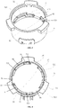
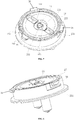
- Fig. 1 is an exploded schematic view of a coffee box according to the first embodiment.
- Fig. 2 is a top view of the coffee box in Fig. 1 .
- the coffee box of this embodiment includes a shell 5, a drip tray 2 and a filter screen assembly 1.
- the filter screen assembly 1 includes a filter screen 12 and an elastic filter tray 11.
- the filter screen 12, the elastic filter tray 11 and the drip tray 2 are detachably installed in the shell 5 and arranged along the top-to-bottom direction.
- the shell 5 is cylindrical in shape, and an outer wall of the shell 5 is provided with a handle 7 to facilitate the use of the coffee box.
- a first limiting structure, a second limiting structure and a third limiting structure are provided inside the shell 5.
- the first limiting structure and the second limiting structure are located at different positions in the axial direction of the shell 5, that is, the first limiting structure and the second limiting structure are arranged at different heights in the shell 5.
- the first limiting structure is closer to the bottom of the shell 5 than the second limiting structure.
- the first limiting structure includes at least two first limiting parts 51 spaced apart along the circumferential direction of the shell 5.
- the second limiting structure includes at least two second limiting parts 52 spaced apart along the circumferential direction of the shell 5.
- Each first limiting part 51 and each second limiting part 52 protrude from the inner surface of the side wall of the shell 5 and extend along the circumferential direction of the shell 5.
- the first limiting parts 51 have three in number and they are evenly spaced
- the second limiting parts 52 have three in number and they are evenly spaced.
- the first limiting parts 51 are closer to the bottom of the shell 5 than the second limiting parts 52.
- One second limiting part 52 is arranged between two adjacent first limiting parts 51.
- a passage 56 is provided between each first limiting part 51 and a neighboring second limiting part 52 for the drip tray 2 to insert from the bottom of the shell 5 and move upward towards the top of the shell 5. According to the number and size of the passages 56 as required, the circumferential distance between each first limiting part 51 and the neighboring second limiting part 52 can be adjusted.
- the third limiting structure protrudes from the side surface of the first limiting structure or the second limiting structure.
- the third limiting structure is a limiting block 53 protruding from the side surface of one first limiting part 51 or one second limiting part 52.
- the third limiting structure can also be a limiting block 53 protruding from the inner wall of the shell 5, so long as the front end of the limiting block 53 extends beyond the side surface of the first limiting part 51 or the second limiting part 52, and the limiting block 53 can be cooperated with the drip tray 2 without interference to the movement of the drip tray 2.
- the drip tray 2 is provided with a fourth limiting structure and a fifth limiting structure.
- the fourth limiting structure is used to cooperate with the third limiting structure to restrict the rotation direction of the drip tray 2.
- the fifth limiting structure is used to cooperate with the first limiting structure or the second limiting structure to fix the drip tray 2 at different positions in the axial direction of the shell 5.
- the fifth limiting structure includes at least two fifth limiting parts 26 spaced apart along the circumferential direction of the drip tray 2.
- the fifth limiting parts 26 protrude from the outer surface of the side wall of the drip tray 2 and are located on the same plane.
- the fifth limiting parts 26 have three in number and they are evenly spaced.
- the lower surface of the fifth limiting part 26 is cooperated with the upper surface of the first limiting part 51 or the second limiting part 52 for positioning.
- the upper surface of the first limiting part 51 is provided with a first limiting protrusion 511
- the upper surface of the second limiting part 52 is provided with a second limiting protrusion 521
- the lower surface of the fifth limiting part 26 is provided with a limiting groove 261
- the limiting groove 261 is cooperated with the first limiting protrusion 511 or the second limiting protrusion 521 to restrict the circumferential movement of the drip tray 2 at different axial positions, that is, to restrict the rotation of the drip tray 2.
- the fourth limiting structure includes a first sliding groove 251 and a second sliding groove 252 spaced apart on the outer surface of the side wall of the drip tray 2.
- the first sliding groove 251 and the second sliding groove 252 each extend along the circumferential direction of the drip tray 2, and the second sliding groove 252 is closer to the top of the drip tray 2 than the first sliding groove 251.
- the first sliding groove 251 is located under one of the fifth limiting parts 26, and the second sliding groove 252 is located between the other two fifth limiting parts 26.
- the drip tray 2 when the first sliding groove 251 is aligned with the limiting block 53, the drip tray 2 can be inserted from the bottom of the shell 5 to a height so that the lower surface of the fifth limiting part 26 is substantially flush with the upper surface of the second limiting part 52. At this time, the drip tray 2 can rotate clockwise (in a second direction) with respect to the shell 5, so that the limiting block 53 slides in the first sliding groove 251, and the fifth limiting part 26 is rotated to cooperate with the second limiting part 52. At this time, the limiting groove 261 on the lower surface of the fifth limiting part 26 is engaged with the second limiting protrusion 521 for positioning in the circumferential direction.
- the lower surface of the fifth limiting part 26 abuts against the upper surface of the second limiting part 52, and the limiting block 53 abuts against the lower surface of the first sliding groove 251 to realize axial positioning.
- the drip tray 2 is thus fixed at a relatively high position in the shell 5, and a filter screen 12 with a smaller capacity, such as a single cup filter screen, may be selected.
- the drip tray 2 when the second sliding groove 252 is aligned with the limiting block 53, the drip tray 2 can be inserted from the bottom of the shell 5 to a height so that the lower surface of the fifth limiting part 26 is substantially flush with the upper surface of the first limiting part 51. At this time, the drip tray 2 can rotate counterclockwise (in a first direction) with respect to the shell 5, so that the limiting block 53 slides in the second sliding groove 252, and the fifth limiting part 26 is rotated to cooperate with the first limiting part 51. At this time, the limiting groove 261 on the lower surface of the fifth limiting part 26 is engaged with the first limiting protrusion 511 for positioning in the circumferential direction.
- the lower surface of the fifth limiting part 26 abuts against the upper surface of the first limiting part 51, and the limiting block 53 abuts against the lower surface of the second sliding groove 252 to realize axial positioning.
- the drip tray 2 is thus fixed in a relatively low position in the shell 5, and a filter screen 12 with a larger capacity, such as a double cup filter screen, may be selected.
- the first limiting parts 51 and the second limiting parts 52 are located at different positions in the axial direction of the shell 5.
- the limiting block 53 is used to cooperate with the second sliding groove 252, so that the drip tray 2 can rotate in the first direction to cause the fifth limiting parts 26 to be engaged and fixed with the first limiting parts 51 and accordingly form, for example, a double cup structure.
- the coffee box can be used to contain a corresponding amount of coffee powder for two cups of coffee.
- the limiting block 53 is further used to cooperate with the first sliding groove 251, so that the drip tray 2 can rotate in the second direction to cause the fifth limiting parts 26 to be engaged and fixed with the second limiting parts 52 and accordingly form, for example, a single cup structure.
- the coffee box can be used to contain a corresponding amount of coffee powder for a single cup of coffee.
- the first direction is opposite to the second direction.
- the upper space formed by the drip tray 2 and the shell 5 is used to install the filter screen assembly 1, wherein the elastic filter tray 11 is disposed above the drip tray 2 and the filter screen 12 is disposed above the elastic filter tray 11.
- the depth of the filter screen 12 used in the double cup structure is greater than that of the filter screen 12 used in the single cup structure. Therefore, only two filter screens 12 with different depths are needed in order to make different amounts of coffee, so that the production cost is low. Meanwhile, the single cup structure and the double cup structure can be switched simply, and the whole structure is detachable and easy to clean.
- the height of the filter screen 12 can also be adjusted by designing the filter screen 12 into a retractable structure. In this way, it is only necessary to adjust the height of the filter screen 12 according to the installation height of the drip tray 2 in order to realize the switching of the single or double cup structure, without the need to provide two different filter screens 12.
- this embodiment only uses “single cup” and “double cup” as examples to illustrate the difference of coffee powder capacity corresponding to the coffee box under different mounting positions of the drip tray 2. It is not used to limit that the present invention can only have “single cup” and “double cup” coffee powder capacity under different mounting positions of the drip tray 2, for example, it can also be single cup and three cup, or double cup and three cup, or any other different capacities.
- the elastic filter tray 11 is disposed above the drip tray 2.
- the drip tray 2 is provided with an extraction groove 21 and a coffee outlet channel 22, and the extraction groove 21 is in fluid communication with the coffee outlet channel 22.
- the elastic filter tray 11 is provided with at least one filtering hole 111 at the position corresponding to the extraction groove 21. Under the action of pressure, the coffee liquid extracted for the first time can enter the extraction groove 21 via the at least one filtering hole 111 for secondary pressure extraction.
- the extraction groove 21 is arranged centrally in the drip tray 2, and the at least one filtering hole 111 is arranged centrally in the elastic filter tray 11.
- the number of the filtering hole 111 is preferably one.
- the elastic filter tray 11 may be detachably mounted to the drip tray 2. Specifically, the upper surface of the drip tray 2 is provided with a mounting groove 27, and the lower surface of the elastic filter tray 11 is provided with a mounting rib 113. The mounting rib 113 of the elastic filter tray 11 is clamped into the mounting groove 27 of the drip tray 2 to realize detachable installation, so that the structure is simple and it is easy for cleaning.
- the elastic filter tray 11 is made of an elastic material such as silicone. During the extraction process, the coffee liquid above the elastic filter tray 11 is rapidly ejected from the filtering hole 111 under pressure, and then collides with the coffee liquid in the extraction groove 21 or the inner wall of the extraction groove 21 for dispersion, so that the components in the coffee liquid are more evenly dispersed for secondary pressure extraction.
- the extraction pressure above the elastic filter tray 11 can be adjusted by configuring the pore size and number of the filtering hole 111. The smaller the size or number the filtering hole 111 is, the greater the extraction pressure is. On the contrary, the larger the size or number the filtering hole 111 is, the smaller the extraction pressure is.
- high pressure extraction, low pressure extraction or normal pressure extraction can be realized, wherein the pressure of low pressure extraction is greater than the pressure of normal pressure extraction.
- the side wall of the extraction groove 21 includes a high part 211 and a low part 212.
- the high part 211 and the low part 212 jointly define the space of the extraction groove 21.
- the high part 211 abuts against the lower surface of the elastic filter tray 11 to support the elastic filter tray 11.
- a coffee liquid outlet is formed between the lower part 212 and the lower surface of the elastic filter tray 11 to enable the extraction groove 21 to be in fluid communication with the coffee outlet channel 22.
- the coffee outlet channel 22 includes a buffer passage 221 and a discharge passage 222.
- the buffer passage 221 is arranged in a circle around the extraction groove 21.
- the buffer passage 221 is in fluid communication with the liquid outlet 23 of the drip tray 2 through the discharge passage 222.
- a buffer wall 223 is provided at the connection point between the buffer passage 221 and the discharge passage 222, and a middle portion of the buffer wall 223 is depressed to form a cutout for liquid guiding.
- the discharge passage 222 includes a horizontal part, an inclined part and a vertical part, wherein the horizontal part is in fluid communication with the buffer passage 221, the vertical part is in fluid communication with the liquid outlet 23 of the drip tray 2, and the inclined part is in fluid communication with both the horizontal part and the vertical part.
- the coffee liquid flowing out of the extraction groove 21 first enters the buffer passage 221. Since the buffer wall 223 is located at the connection point between the buffer passage 221 and the discharge passage 222, the coffee liquid flowing into the buffer passage 221 will not discharge out of the drip tray 2 quickly, and the liquid outflow process is uniform and stable.
- the number of the liquid outlet 23 of the drip tray 2 is two and the two liquid outlets 23 are symmetrically arranged.
- the side wall of the extraction groove 21 includes two lower parts 212 which are symmetrically arranged to form two symmetrical coffee liquid outlets.
- the coffee outlet channel 22 includes two discharge passages 222 which are symmetrically arranged, and each discharge passage 222 corresponds to one liquid outlet 23 of the drip tray 2.
- the connecting line between the two lower parts 212 is orthogonal to the connecting line between the two discharge passages 222. Because the buffer passage 221 and the buffer wall 223 are provided, liquid distribution of the two liquid outlets 23 is uniform, and the liquid output amount from the two liquid outlets 23 is substantially the same, so that the coffee in each cup is uniform. In practice, only one or a plurality of liquid outlets 23 can be provided, which is not limited herein.
- the elastic filter tray 11 further includes a surrounding wall 112 disposed on the upper edge of the elastic filter tray 11, and the surrounding wall 112 is used to abut against the lower surface of the filter screen 12 to form a temporary storage space for coffee liquid in the elastic filter tray 11.
- the filter screen 12 is a single-layer structure and is detachably connected with the shell 5. For example, as shown in Fig. 1 , the filter screen 12 is clamped on the shell 5 through a retaining ring 6, and the single-layer filter screen 12 is cooperated with the elastic filter tray 11 to realize coffee extraction and reduce the probability of blockage of the filter screen assembly 1.
- the drip tray 2 is rotated into the shell 5 from a corresponding direction and fixed at a corresponding height. Then, the elastic filter tray 11 is installed above the drip tray 2, and the filter screen 12 with a corresponding size is selected and installed above the elastic filter tray 11. After that, the filter screen 12 is filled with coffee powder, and then the coffee box is installed on a brewing head of a coffee machine. A coffee extraction chamber is formed between the coffee box and the brewing head of the coffee machine. The brewing head flushes hot water into the coffee box and forms an extraction pressure. The filter screen 12 is used to filter the coffee powder to obtain coffee liquid extracted for the first time. After that, the coffee liquid extracted for the first time enters the extraction groove 21 of the drip tray 2 via the filtering hole 111 of the elastic filter tray 11 under pressure, and is discharged after the second pressure extraction for drinking.
- the coffee box of the present invention includes a shell and a drip tray.
- a first limiting structure, a second limiting structure and a third limiting structure are provided inside the shell.
- the first limiting structure and the second limiting structure are located at different positions in the axial direction of the shell.
- the drip tray is provided with a fourth limiting structure and a fifth limiting structure.
- the drip tray can be rotated in a first direction to cause the fifth limiting structure to be engaged and fixed with the first limiting structure.
- the drip tray can further be rotated in a second direction to cause the fifth limiting structure to be engaged and fixed with the second limiting structure.
- the upper space formed between the drip tray and the shell is used to install the filter screen assembly.
- the drip tray of the coffee box of the present invention can be installed at different positions from different directions to adjust the capacity of the coffee box, the operation is simple, without the need to use various coffee boxes of different specifications to make different quantities of coffee, so that the production cost is low.
- the elastic filter tray is arranged on the top of the drip tray, the drip tray is provided with an extraction groove and a coffee outlet channel, the extraction groove is in fluid communication with the coffee outlet channel, and the elastic filter tray is provided with at least one filtering hole at the position corresponding to the extraction groove.
- the coffee liquid extracted for the first time can enter the extraction groove via the at least one filtering hole for secondary pressure extraction.
- the structure is simple and can be used for the second pressure extraction of coffee.
- the filtering hole on the elastic filter tray can be elastically deformed and is not easy to be blocked, to ensure the pressure stability of each extraction and improve the taste of coffee.
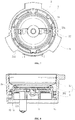
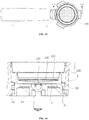
- Fig. 13 is a top schematic view of a coffee box according to the second embodiment.
- Fig. 14 is a sectional view of the coffee box in Fig. 13 along the III-III line.
- the coffee box of this embodiment includes a shell 5, a drip tray 2 and a filter screen assembly 100.
- the filter screen assembly 100 and the drip tray 2 are detachably installed in the shell 5 and arranged along the top-to-bottom direction.
- the shell 5 is cylindrical in shape, and an outer wall of the shell 5 is provided with a handle 7 to facilitate the use of the coffee box.
- a first limiting structure, a second limiting structure and a third limiting structure are provided inside the shell 5.
- the first limiting structure and the second limiting structure are located at different positions in the axial direction of the shell 5, that is, the first limiting structure and the second limiting structure are arranged at different heights in the shell 5.
- the first limiting structure includes at least two first limiting parts 51 spaced apart along the circumferential direction of the shell 5.
- the second limiting structure includes at least two second limiting parts 52 spaced apart along the circumferential direction of the shell 5.
- Each first limiting part 51 and each second limiting part 52 protrude from the inner surface of the side wall of the shell 5 and extend along the circumferential direction of the shell 5.
- the first limiting parts 51 have three in number and they are evenly spaced
- the second limiting parts 52 have three in number and they are evenly spaced.
- the first limiting parts 51 are closer to the bottom of the shell 5 than the second limiting parts 52.
- One second limiting part 52 is arranged between two adjacent first limiting parts 51.
- a passage 56 is provided between each first limiting part 51 and a neighboring second limiting part 52 for the drip tray 2 to insert from the bottom of the shell 5 and move upward towards the top of the shell 5.
- the third limiting structure protrudes from the side surface of the first limiting structure or the second limiting structure.
- the third limiting structure is a limiting block 53 protruding from the side surface of one first limiting part 51 or one second limiting part 52.
- the third limiting structure can also be a limiting block 53 protruding from the inner wall of the shell 5, so long as the front end of the limiting block 53 extends beyond the side surface of the first limiting part 51 or the second limiting part 52, and the limiting block 53 can be cooperated with the drip tray 2 without interference to the movement of the drip tray 2.
- the drip tray 2 is provided with a fourth limiting structure and a fifth limiting structure.
- the fourth limiting structure is used to cooperate with the third limiting structure to restrict the rotation direction of the drip tray 2.
- the fifth limiting structure is used to cooperate with the first limiting structure or the second limiting structure to fix the drip tray 2 at different positions in the shell 5.
- the fifth limiting structure includes at least two fifth limiting parts 26 spaced apart along the circumferential direction of the drip tray 2.
- the fifth limiting parts 26 protrude from the outer surface of the side wall of the drip tray 2 and are located on the same plane.
- the fifth limiting parts 26 have three in number and they are evenly spaced.
- the lower surface of the fifth limiting part 26 is cooperated with the upper surface of the first limiting part 51 or the second limiting part 52 for positioning.
- the upper surface of the first limiting part 51 is provided with a first limiting protrusion 511
- the upper surface of the second limiting part 52 is provided with a second limiting protrusion 521
- the lower surface of the fifth limiting part 26 is provided with a limiting groove 261
- the limiting groove 261 is cooperated with the first limiting protrusion 511 or the second limiting protrusion 521 to restrict the circumferential movement of the drip tray 2 at different axial positions, that is, to restrict the rotation of the drip tray 2.
- the fourth limiting structure includes a first sliding groove 251 and a second sliding groove 252 spaced apart on the outer surface of the side wall of the drip tray 2.
- the first sliding groove 251 and the second sliding groove 252 each extend along the circumferential direction of the drip tray 2, and the second sliding groove 252 is closer to the top of the drip tray 2 than the first sliding groove 251.
- the fifth limiting part 26 is aligned with the passage 56 between the first limiting part 51 and the second limiting part 52.
- the drip tray 2 can be inserted into a corresponding height from the bottom of the shell 5, and the rotation direction of the drip tray 2 at this height is determined by the cooperation of the first sliding groove 251 or the second sliding groove 252 with the limiting block 53.
- the filter screen assembly 100 in this embodiment is a double-layer filter screen.
- the filter screen assembly 100 includes an upper filter screen 101 and a lower filter screen 102.
- the lower filter screen 102 is provided with at least one filtering hole 103 at the position corresponding to the extraction groove 21 of the drip tray 2.
- the coffee liquid extracted for the first time can enter the drip tray 2 via at least one filtering hole 103 for secondary extraction, and the structure is simple.
- the flow channel structure of the drip tray 2 can refer to the description in the first embodiment and will not be repeated herein again.
- the drip tray can be installed at different positions from different directions to adjust the capacity of the coffee box, and the operation is simple, without the need to provide various coffee boxes of different specifications to make different quantities of coffee, so that the production cost is low.
Landscapes
- Engineering & Computer Science (AREA)
- Food Science & Technology (AREA)
- Apparatus For Making Beverages (AREA)
Applications Claiming Priority (2)
| Application Number | Priority Date | Filing Date | Title |
|---|---|---|---|
| CN202020099672.3U CN211748882U (zh) | 2020-01-16 | 2020-01-16 | 咖啡萃取组件及具有其的咖啡盒 |
| CN202010048470.0A CN113133659B (zh) | 2020-01-16 | 2020-01-16 | 咖啡盒 |
Publications (1)
| Publication Number | Publication Date |
|---|---|
| EP3850996A1 true EP3850996A1 (de) | 2021-07-21 |
Family
ID=74105815
Family Applications (1)
| Application Number | Title | Priority Date | Filing Date |
|---|---|---|---|
| EP21150355.2A Withdrawn EP3850996A1 (de) | 2020-01-16 | 2021-01-06 | Kaffeeextraktionsanordnung und kaffeebehälter für eine kaffeemaschine |
Country Status (2)
| Country | Link |
|---|---|
| US (1) | US20210219768A1 (de) |
| EP (1) | EP3850996A1 (de) |
Cited By (1)
| Publication number | Priority date | Publication date | Assignee | Title |
|---|---|---|---|---|
| IT202300027627A1 (it) * | 2023-12-21 | 2025-06-21 | Amici Caffe Ag | Portafiltro per macchine da caffè e relativo espulsore per cialde |
Families Citing this family (1)
| Publication number | Priority date | Publication date | Assignee | Title |
|---|---|---|---|---|
| EP4444145A1 (de) * | 2021-12-09 | 2024-10-16 | La Marzocco S.r.l. | Trennbarer filterhalter für espresso-kaffeemaschine |
Citations (4)
| Publication number | Priority date | Publication date | Assignee | Title |
|---|---|---|---|---|
| US6752070B1 (en) * | 2003-09-15 | 2004-06-22 | Uni-Splendor Corp. | Filter assembly of coffee maker |
| KR200440656Y1 (ko) * | 2007-03-02 | 2008-06-24 | 정우영 | 기호음료 제조장치 |
| ITMI20101499A1 (it) * | 2010-08-05 | 2012-02-06 | Mo El Srl | Metodo e macchina per la produzione di caffè espresso |
| GB2505041A (en) * | 2012-06-14 | 2014-02-19 | Tsann Kuen Zhangzhou Entpr Co | A detachable filtering element of a coffee machine |
Family Cites Families (1)
| Publication number | Priority date | Publication date | Assignee | Title |
|---|---|---|---|---|
| DE19832063C5 (de) * | 1998-07-16 | 2004-10-21 | Maxs Ag | Espressobrühkopfeinheit |
-
2020
- 2020-12-31 US US17/139,796 patent/US20210219768A1/en not_active Abandoned
-
2021
- 2021-01-06 EP EP21150355.2A patent/EP3850996A1/de not_active Withdrawn
Patent Citations (4)
| Publication number | Priority date | Publication date | Assignee | Title |
|---|---|---|---|---|
| US6752070B1 (en) * | 2003-09-15 | 2004-06-22 | Uni-Splendor Corp. | Filter assembly of coffee maker |
| KR200440656Y1 (ko) * | 2007-03-02 | 2008-06-24 | 정우영 | 기호음료 제조장치 |
| ITMI20101499A1 (it) * | 2010-08-05 | 2012-02-06 | Mo El Srl | Metodo e macchina per la produzione di caffè espresso |
| GB2505041A (en) * | 2012-06-14 | 2014-02-19 | Tsann Kuen Zhangzhou Entpr Co | A detachable filtering element of a coffee machine |
Cited By (2)
| Publication number | Priority date | Publication date | Assignee | Title |
|---|---|---|---|---|
| IT202300027627A1 (it) * | 2023-12-21 | 2025-06-21 | Amici Caffe Ag | Portafiltro per macchine da caffè e relativo espulsore per cialde |
| WO2025133912A1 (en) * | 2023-12-21 | 2025-06-26 | Amici Caffe' Ag | Filter holder for coffee machines and related ejector for pods |
Also Published As
| Publication number | Publication date |
|---|---|
| US20210219768A1 (en) | 2021-07-22 |
Similar Documents
| Publication | Publication Date | Title |
|---|---|---|
| EP3850996A1 (de) | Kaffeeextraktionsanordnung und kaffeebehälter für eine kaffeemaschine | |
| US4149454A (en) | Coffeemaker basket and filter assembly | |
| AU739554B2 (en) | Apparatus for preparing coffee having a small-bubbled foam layer | |
| EP1690479B1 (de) | Auslass von Kaffeemaschinen | |
| US20030226449A1 (en) | Coffee Filter holder | |
| US9907433B2 (en) | Universal water filter assembly for multiple coffee makers | |
| US20170188745A1 (en) | Filter Assembly for a Beverage Dispenser | |
| US10820738B2 (en) | Collection receptacle for collecting insoluble material that is used for preparing beverages, as well as infusion device with such a collection receptacle | |
| JP6647393B2 (ja) | コーヒーメーカーおよびコーヒー製造方法 | |
| WO2018194475A1 (pt) | Sistema de distribuição de bebidas com disposição de descarga de bebidas optimizada | |
| JP3215340U (ja) | 醸造室の構造が改善されたコーヒーメーカー | |
| CN113133659B (zh) | 咖啡盒 | |
| CN106175460A (zh) | 一种咖啡机 | |
| JP7344670B2 (ja) | コーヒーメーカー | |
| EP4193888B1 (de) | Vorrichtung zur ausgabe von espresso-kaffee in grossen mengen | |
| CN108348091B (zh) | 流量可调节的冲泡篮 | |
| CN216962164U (zh) | 气压调节装置及咖啡机 | |
| RU2197885C2 (ru) | Держатель фильтра для кофеварки типа экспресс | |
| CN203852222U (zh) | 一种积水盒 | |
| CN211609502U (zh) | 一种食品加工机 | |
| CN101199392A (zh) | 饮料机 | |
| CN211748882U (zh) | 咖啡萃取组件及具有其的咖啡盒 | |
| JP2017133246A (ja) | 排水弁装置、洗浄水タンク装置及び水洗大便器 | |
| CN100525688C (zh) | 咖啡滤壶 | |
| CN217365404U (zh) | 饮品机的冲泡过滤结构及饮品机 |
Legal Events
| Date | Code | Title | Description |
|---|---|---|---|
| PUAI | Public reference made under article 153(3) epc to a published international application that has entered the european phase |
Free format text: ORIGINAL CODE: 0009012 |
|
| STAA | Information on the status of an ep patent application or granted ep patent |
Free format text: STATUS: THE APPLICATION HAS BEEN PUBLISHED |
|
| AK | Designated contracting states |
Kind code of ref document: A1 Designated state(s): AL AT BE BG CH CY CZ DE DK EE ES FI FR GB GR HR HU IE IS IT LI LT LU LV MC MK MT NL NO PL PT RO RS SE SI SK SM TR |
|
| STAA | Information on the status of an ep patent application or granted ep patent |
Free format text: STATUS: REQUEST FOR EXAMINATION WAS MADE |
|
| 17P | Request for examination filed |
Effective date: 20210917 |
|
| RBV | Designated contracting states (corrected) |
Designated state(s): AL AT BE BG CH CY CZ DE DK EE ES FI FR GB GR HR HU IE IS IT LI LT LU LV MC MK MT NL NO PL PT RO RS SE SI SK SM TR |
|
| GRAP | Despatch of communication of intention to grant a patent |
Free format text: ORIGINAL CODE: EPIDOSNIGR1 |
|
| STAA | Information on the status of an ep patent application or granted ep patent |
Free format text: STATUS: GRANT OF PATENT IS INTENDED |
|
| RIC1 | Information provided on ipc code assigned before grant |
Ipc: A47J 31/06 20060101ALI20231128BHEP Ipc: A47J 31/44 20060101AFI20231128BHEP |
|
| INTG | Intention to grant announced |
Effective date: 20231222 |
|
| RAP3 | Party data changed (applicant data changed or rights of an application transferred) |
Owner name: TSANN KUEN (ZHANG ZHOU) ENTERPRISE CO., LTD |
|
| STAA | Information on the status of an ep patent application or granted ep patent |
Free format text: STATUS: THE APPLICATION IS DEEMED TO BE WITHDRAWN |
|
| 18D | Application deemed to be withdrawn |
Effective date: 20240423 |