EP3850930B1 - Adapter eines landwirtschaftlichen anbaugeräts und landwirtschaftliches anbaugerät - Google Patents
Adapter eines landwirtschaftlichen anbaugeräts und landwirtschaftliches anbaugerät Download PDFInfo
- Publication number
- EP3850930B1 EP3850930B1 EP21151143.1A EP21151143A EP3850930B1 EP 3850930 B1 EP3850930 B1 EP 3850930B1 EP 21151143 A EP21151143 A EP 21151143A EP 3850930 B1 EP3850930 B1 EP 3850930B1
- Authority
- EP
- European Patent Office
- Prior art keywords
- attachment
- adapter
- agricultural
- category
- attachment system
- Prior art date
- Legal status (The legal status is an assumption and is not a legal conclusion. Google has not performed a legal analysis and makes no representation as to the accuracy of the status listed.)
- Active
Links
Images


Classifications
-
- A—HUMAN NECESSITIES
- A01—AGRICULTURE; FORESTRY; ANIMAL HUSBANDRY; HUNTING; TRAPPING; FISHING
- A01B—SOIL WORKING IN AGRICULTURE OR FORESTRY; PARTS, DETAILS, OR ACCESSORIES OF AGRICULTURAL MACHINES OR IMPLEMENTS, IN GENERAL
- A01B59/00—Devices specially adapted for connection between animals or tractors and agricultural machines or implements
- A01B59/002—Details, component parts
-
- A—HUMAN NECESSITIES
- A01—AGRICULTURE; FORESTRY; ANIMAL HUSBANDRY; HUNTING; TRAPPING; FISHING
- A01B—SOIL WORKING IN AGRICULTURE OR FORESTRY; PARTS, DETAILS, OR ACCESSORIES OF AGRICULTURAL MACHINES OR IMPLEMENTS, IN GENERAL
- A01B59/00—Devices specially adapted for connection between animals or tractors and agricultural machines or implements
- A01B59/04—Devices specially adapted for connection between animals or tractors and agricultural machines or implements for machines pulled or pushed by a tractor
- A01B59/042—Devices specially adapted for connection between animals or tractors and agricultural machines or implements for machines pulled or pushed by a tractor having pulling means arranged on the rear part of the tractor
-
- A—HUMAN NECESSITIES
- A01—AGRICULTURE; FORESTRY; ANIMAL HUSBANDRY; HUNTING; TRAPPING; FISHING
- A01B—SOIL WORKING IN AGRICULTURE OR FORESTRY; PARTS, DETAILS, OR ACCESSORIES OF AGRICULTURAL MACHINES OR IMPLEMENTS, IN GENERAL
- A01B59/00—Devices specially adapted for connection between animals or tractors and agricultural machines or implements
- A01B59/06—Devices specially adapted for connection between animals or tractors and agricultural machines or implements for machines mounted on tractors
- A01B59/061—Devices specially adapted for connection between animals or tractors and agricultural machines or implements for machines mounted on tractors specially adapted for enabling connection or disconnection controlled from the driver's seat
- A01B59/062—Devices specially adapted for connection between animals or tractors and agricultural machines or implements for machines mounted on tractors specially adapted for enabling connection or disconnection controlled from the driver's seat the connection comprising a rigid interface frame on the tractor
-
- B—PERFORMING OPERATIONS; TRANSPORTING
- B60—VEHICLES IN GENERAL
- B60D—VEHICLE CONNECTIONS
- B60D1/00—Traction couplings; Hitches; Draw-gear; Towing devices
- B60D1/01—Traction couplings or hitches characterised by their type
- B60D1/07—Multi-hitch devices, i.e. comprising several hitches of the same or of a different type; Hitch-adaptors, i.e. for converting hitches from one type to another
- B60D1/075—Hitch adaptors
-
- B—PERFORMING OPERATIONS; TRANSPORTING
- B60—VEHICLES IN GENERAL
- B60D—VEHICLE CONNECTIONS
- B60D1/00—Traction couplings; Hitches; Draw-gear; Towing devices
- B60D1/14—Draw-gear or towing devices characterised by their type
- B60D1/141—Arrangements or frames adapted to allow the connection of trailers to tractor three-point hitches
-
- A—HUMAN NECESSITIES
- A01—AGRICULTURE; FORESTRY; ANIMAL HUSBANDRY; HUNTING; TRAPPING; FISHING
- A01B—SOIL WORKING IN AGRICULTURE OR FORESTRY; PARTS, DETAILS, OR ACCESSORIES OF AGRICULTURAL MACHINES OR IMPLEMENTS, IN GENERAL
- A01B59/00—Devices specially adapted for connection between animals or tractors and agricultural machines or implements
- A01B59/002—Details, component parts
- A01B59/008—Link connectors with spherical surfaces
-
- B—PERFORMING OPERATIONS; TRANSPORTING
- B60—VEHICLES IN GENERAL
- B60D—VEHICLE CONNECTIONS
- B60D1/00—Traction couplings; Hitches; Draw-gear; Towing devices
- B60D2001/001—Traction couplings; Hitches; Draw-gear; Towing devices specially adapted for use on vehicles other than cars
- B60D2001/008—Traction couplings; Hitches; Draw-gear; Towing devices specially adapted for use on vehicles other than cars specially adapted for implements, e.g. towed tools
Definitions
- the invention relates to an adapter for an agricultural attachment and an agricultural attachment.
- an agricultural implement In agricultural machine technology, it is common for an agricultural implement to be coupled to an agricultural carrier vehicle.
- the agricultural carrier vehicle can have a US quick hitch attachment system or a European lower link attachment system to which an attachment can be coupled.
- the attachment Depending on whether the carrier vehicle has a US quick hitch attachment system or a European lower link attachment system, the attachment must have a corresponding adapter in order to couple the attachment to the carrier vehicle via the adapter.
- the patent US 3,472,528A discloses a tractor implement coupling for connecting a working implement to a coupling linkage of a tractor, with an adapter device being interposed between the coupling linkage of the tractor and the working implement, which has coupling elements with at least two different diameters for each coupling point both on the tractor and on the working implement side.
- DE 1 957 228 A1 discloses a coupling element for an attachment that can be connected to an agricultural motor vehicle by means of an attachment device provided with catching elements, and consists of a bushing that can be pushed with a sliding fit onto a coupling pin attached to the attachment transversely to the direction of pull, which can be fixed axially and on its fixed End of the coupling pin end facing away from the insertion into the catching members serving collar, wherein the socket and / or the collar on the coupling pin is gradually axially adjustable.
- the object of the present invention is to create a new type of adapter for an agricultural attachment and an agricultural attachment.
- the adapter has a first, cylindrically contoured section, the outer diameter of which is designed to couple the agricultural attachment to a US quick hitch attachment system of an agricultural carrier vehicle, and a second, spherically contoured section, the outer diameter of which is designed to to couple agricultural attachments with a European lower link attachment system of an agricultural carrier vehicle.
- the invention proposes an adapter for an agricultural attachment that enables flexible connection of an agricultural attachment to different attachment systems of an agricultural carrier vehicle. both to a US quick hitch attachment system and to a European lower link attachment system. Accordingly, it is no longer necessary to have different adapters ready for different attachment systems of carrier vehicles.
- the adapter is designed as a one-piece or one-piece adapter socket, which has a recess via which the same can be pushed onto a carrier bolt.
- This configuration of the adapter makes it possible to easily couple an agricultural attachment to different attachment systems of an agricultural carrier vehicle using the adapter. To adapt, the adapter simply has to be pushed onto the carrier bolt in a defined orientation.
- a first thrust washer with a starting bevel facing the cylindrically contoured section is formed on a first side of the cylindrically contoured section, with a second thrust washer with a starting bevel facing the cylindrically contoured section and preferably, furthermore, a run-on bevel facing the spherically contoured section is formed.
- the thrust washers facilitate the coupling of the attachment to the carrier vehicle, namely the coupling of the mounting system of the carrier vehicle to the adapter of the attachment.
- the cylindrically contoured section has a length that corresponds to the width of the US quick hitch attachment system, in particular the length of a US quick hitch attachment system of category 2 or category 3N or category 3, wherein the spherically contoured portion has a diameter corresponding to the diameter of the European drop arm mounting system, in particular the diameter of a Category II or Category III European drop arm mounting system.
- This dimensioning of the adapter is particularly preferred in order to ensure the same flexibility with regard to the coupling of an attachment to different attachment systems.
- the agricultural attachment according to the invention is defined in claim 7.
- the agricultural attachment according to the invention has receptacles and adapters according to the invention, which are mounted on the receptacles. Such an attachment can be flexibly coupled to different attachment systems of an agricultural carrier vehicle.
- the respective receptacle has two tabs spaced apart from one another, on which the respective adapter is mounted. This embodiment is preferred in order to couple the attachment to an agricultural carrier vehicle using the adapter.
- a lateral distance between tabs facing one another of the mounts of the attachment maximum an inside dimension of a hook spacing of the US quick hitch attachment system.
- a lateral spacing between tabs of the receptacles of the attachment that face away from one another corresponds at least to an external dimension of the hook spacing of the US quick-hitch attachment system.
- the tabs have insertion bevels when viewed in the direction of insertion of the attachment system. This development is preferred in order to enable the attachment system of the agricultural carrier vehicle to be coupled to the adapter of the agricultural attachment via the insertion bevels.
- the invention relates to an adapter for an agricultural attachment and an agricultural attachment.
- FIG 1 and 2 show different views of a section of an agricultural attachment 20 together with an attachment system 21 of an agricultural carrier vehicle, wherein the agricultural attachment 20 can be coupled via the attachment system 21 to the agricultural carrier vehicle, which is not shown in detail.
- Attachment system 21 shown is a Category 2 or Category 3N US quick hitch attachment system. This has a transom 22 and hooks 23 attached to one side of the transom 22.
- a quick hitch attachment system is typically located on a hitch system of a carrier vehicle such as an agricultural tractor.
- a longitudinal beam 24 as well as spars 25 acting laterally on the longitudinal beam 24 are shown.
- the agricultural attachment 20 has receptacles 26 for adapters 27, with adapters 27 accommodated in the receptacles 26 ultimately serving to couple the agricultural attachment 20 to the attachment system 21 of the agricultural carrier vehicle.
- an adapter 27 is proposed, which enables the attachment 20 to be connected to different attachment systems of an agricultural carrier vehicle.
- 11 shows this adapter 27 on its own.
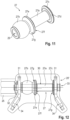
- 10 and 12 show the adapter 27 together with a respective receptacle 26 or 26 ⁇ of the attachment 20.
- the adapter 27 has a first, cylindrically contoured section 27a, the outside diameter of which is designed to pair the agricultural attachment 20, which has such adapters, with a US Quick-Hitch after-construction system of an agricultural carrier vehicle, namely in the variant of the 1 , 2 , 13 with a US Quick Hitch attachment system 21 of category 2 or category 3N and in the variant of 3 , 4 and 14 with a US quick-hitch attachment system 21' of category 3.
- a US quick-hitch attachment system 21' of category 3 in turn has a crossbar 22 and on one side of the crossbar 22 arranged hooks 23, with the US - Category 2 or Category 3N quick-hitch attachment system 21 the distance between the hooks 23 is smaller than in the US Category 3 quick-hitch attachment system 21'.
- the adapter 27 has a second, spherically contoured section 27b, the outer diameter of which is designed to couple the agricultural attachment to a European lower link mounting system of an agricultural carrier vehicle via the adapter 27, specifically in the variant of figure 5 and 6 with a European lower link mounting system 21" of category II and in the variant of 7 and 8th with a European category III lower link mounting system 21′′′.
- the European lower link attachment systems 21" and 21′′′ shown each have lower links 28 which differ from one another in terms of their lateral spacing or distance extending transversely to the longitudinal direction and which are used for coupling an attachment 20 to the carrier vehicle on the second, spherically contoured sections 27b of the respective Attack adapter 27.
- the two sections 27a, 27b of the adapter 27 are positioned side by side.
- the adapter 27 is designed as a one-piece or one-piece or monolithic adapter bushing, which has a recess 29 through which the adapter bushing can be pushed onto a carrier bolt 30 .
- the respective adapter 27 can be used to connect the attachment 20 to the different attachment systems 21, 21', 21" and 21′′′ of an agricultural carrier vehicle.
- the adapter 27 are used to the attachment 20 either according to 1 and 2 to a US Quick Hitch Attachment System 21 Category 2 or Category 3N or equivalent 7 and 8th to connect to a European lower link attachment system 21′′′ of category III, the adapters 27 are mounted on the respective carrier bolts 30 in such a way that, in relation to the longitudinal member 24 of the attachment 20, the spherical sections 27b point outwards and the cylindrically contoured sections 27a point inwards point.
- the adapters 27 are used to connect the attachment 20 to a category 3 US quick-hitch attachment system or to connect the attachment 20 to a category II European lower link attachment system 21"
- the adapters 27 are mounted in such a way that, based on on the trailing arm 24 of the attachment 20, the spherically contoured sections 27b point inwards and the cylindrically contoured sections 27a point outwards.
- the first, cylindrically contoured section 27a of the respective adapter 27 has an outer diameter which corresponds to the diameter of the US quick hitch attachment system.
- the diameters of the US quick hitch attachment systems of categories 2, 3N and 3 are identical, they differ only in terms of the distance between their hooks 23.
- the outer diameter of the spherical or spherically contoured section 27b of the respective adapter 27 corresponds to the inner diameter of the European lower link mounting systems of categories II and III, which have identical inner diameters but differ from one another in the lateral spacing of the lower links 28.
- the adapter 27 On a first side of the cylindrically contoured section 27a, the adapter 27 has a first thrust washer 27c with a starting bevel 27d facing the cylindrically contoured section 27a and on an opposite second end of the cylindrically contoured section 27a, specifically between the cylindrically contoured section 27a and the spherically contoured section 27b, via a second thrust washer 27e with a likewise the cylindrically contoured section 27a facing contact bevel 27f and preferably also a spherically contoured section 27b facing contact bevel 27g.
- the connection of the add-on systems to the adapter 27 is facilitated via these starting bevels 27d, 27f and 27g.
- the cylindrically contoured section 27a of the respective adapter 27 has a length that corresponds to the width of a hook of the US quick hitch attachment system 21 or 21', specifically the length of a hook of the US quick hitch attachment system 21 the category 2 or category 3N or the length of a hook 23 of the US quick hitch attachment system category 3.
- the hooks 23 of these categories 2, 3N and 3 of the US quick hitch attachment system thereby have identical lengths and identical Inside diameter, as already explained, these categories of US quick hitch attachment systems differ in terms of the spacing of the hooks 23.
- the spherically contoured section 27b of the respective adapter 27 has an outer diameter that corresponds to the inner diameter of the European lower link mounting system 21" or 21′′′, whereby, as already stated, a European lower link mounting system of category III and a European lower link mounting system of Category III have identical inner diameters, but differ in terms of the lateral spacing of the lower links 28.
- the thrust washers 27c, 27e of the respective adapter 27 preferably have a defined width b (see 9 ), which is preferably between 2 mm and 6 mm, in particular between 3 mm and 5 mm, particularly preferably around 4 mm.
- the thrust washers 27c, 27e have a radius r and thus a diameter which corresponds approximately to the outer diameter of the spherically contoured section 27b of the adapter 27, preferably a few millimeters larger than the outer diameter of the spherically contoured section 27b of the respective adapter 27 .
- the invention relates not only to the adapter 27 as such, which is preferably designed as an adapter socket, but also to the agricultural attachment 20, which accommodates or carries two such adapters 27 in corresponding receptacles 26 and 26'.
- Each of the receptacles 26 or 26' which accommodates an adapter 27 described above, has two spaced tabs 31, with the respective carrier bolt 30 for the respective adapter 27, which accommodates or carries the adapter 27, which is preferably designed as an adapter bushing, through the opposing tabs 31 of the respective receptacle 26, 26'.
- a cotter pin 32 engages at one end of a carrier bolt 31 for fixing the carrier bolt 30 and thus the adapter 27 received by the carrier bolt 30 on the respective receptacle 26, 26'.
- a preferably circumferential stop 33 in the form of a shoulder, formed, which limits the insertion depth of the respective support bolt 27 in one of the tabs 31 and so also the position fixing of the carrier bolt 30 and thus of the adapter bushing 27 accommodated by the carrier bolt 30 in the region of the respective receptacle 26 .
- the carrier pin 30 could also be secured in its position on both sides by cotter pins 32 .
- the mutually facing tabs 31 of the two receptacles 26 are spaced apart by a distance X, which corresponds at most to an inside dimension of a hook spacing of the hooks 23 of the US quick hitch attachment system 21 of category 2 or category 3N.
- a distance Y between the tabs 31 of the two receptacles 26 facing away from each other corresponds at least to the outer dimension of the hook spacing of the hooks 23 of the US quick hitch attachment system of category 3 or the inner dimension of the hook spacing plus twice the hook width of the hooks 23.
- the invention is preferably used in agricultural attachments 20 which are designed in particular as a mower, windrower, merger or turner.
- the attachment 20 has a receptacle, particularly in the area of its longitudinal member 24, to which in particular an upper hook 35 of a US quick hitch attachment system 21 or 21' or an upper link (not shown) of a European cultivation system can be connected.
Landscapes
- Life Sciences & Earth Sciences (AREA)
- Engineering & Computer Science (AREA)
- Mechanical Engineering (AREA)
- Zoology (AREA)
- Soil Sciences (AREA)
- Environmental Sciences (AREA)
- Transportation (AREA)
- Agricultural Machines (AREA)
Description
- Die Erfindung betrifft einen Adapter eines landwirtschaftlichen Anbaugeräts und ein landwirtschaftliches Anbaugerät.
- In der Landmaschinentechnik ist es üblich, dass ein landwirtschaftliches Anbaugerät an ein landwirtschaftliches Trägerfahrzeug gekoppelt werden muss. So kann das landwirtschaftliche Trägerfahrzeug zum Beispiel über ein US-Quick-Hitch-Anbausystem oder über ein europäisches Unterlenker-Anbausystem verfügen, an welches ein Anbaugerät angekoppelt werden kann. Abhängig davon, ob das Trägerfahrzeug ein US-Quick-Hitch-Anbausystem oder ein europäisches Unterlenker-Anbausystem aufweist, muss das Anbaugerät einen entsprechenden Adapter aufweisen, um über den Adapter das Anbaugerät an das Trägerfahrzeug zu koppeln.
- Da nicht nur zwischen US-Quick-Hitch-Anbausystemen und europäischen Unterlenker-Anbausystemen als solche unterschieden wird, sondern für diese Anbausysteme auch jeweils unterschiedliche Kategorien bestehen, ist es nach der Praxis erforderlich, eine Vielzahl unterschiedlicher Adapter für ein landwirtschaftliches Anbaugerät bereitzuhalten, um dasselbe auch an das entsprechende Anbausystem des landwirtschaftlichen Trägerfahrzeugs koppeln zu können.
- Das Patent
US 3,472,528 A offenbart eine Schlepper-Gerätekupplung zum Verbinden eines Arbeitsgerätes mit einem Kupplungsgestänge eines Schleppers, wobei zwischen dem Kupplungsgestänge des Schleppers und dem Arbeitsgerät eine Adaptervorrichtung zwischengeschaltet ist, die für jeden Kupplungspunkt sowohl schlepper-wie arbeitsgeräteseitig jeweils Kupplungsorgane mit mindestens zwei unterschiedlichen Durchmessern aufweist. - Aus
DE 10 2013 208 279 A1 ist ein landwirtschaftliches Anbau- oder Anhängegerät mit Koppelmitteln zum Verbinden mit einem Lenker einer Dreipunktanbauvorrichtung eines Traktors bekannt, wobei der Lenker eine hakenförmige zu einer Seite offene Ausnehmung aufweist, in welcher die Koppelmittel aufnehmbar sind und die Koppelmittel einseitig an einer Halterung des Anbau- oder Anhängegerätes befestigt sind sowie an ihrem freien Ende mit einem den Lenker zu den Koppelmitteln hinführenden Leitelement versehen sind, wobei mindestens ein weiteres Leitelement vorgesehen ist, welches dem ersten Leitelement gegenübersteht und durch welches der Lenker von der dem freien Ende gegenüberliegenden Halterungsseite aus zu den Koppelmitteln hinführbar ist. -
DE 1 957 228 A1 offenbart ein Kuppelglied für ein Anbaugerät, das mittels einer mit Fanggliedern versehenen Geräteanbauvorrichtung mit einem landwirtschaftlich nutzbaren Motorfahrzeug verbindbar ist, und aus einer, auf einen quer zur Zugrichtung am Anbaugerät angebrachten Kuppelzapfen mit Schiebesitz aufsteckbaren Buchse besteht, die axial fixierbar ist und auf ihrem dem festen Ende des Kuppelzapfens abgewandten Ende einen der Einführung in die Fangglieder dienenden Bund aufweist, wobei die Buchse und/oder deren Bund auf dem Kuppelzapfen stufenweise axial verstellbar ist. - Es besteht Bedarf daran, einen Adapter eines landwirtschaftlichen Anbaugeräts bereitzustellen, der eine flexible Ankopplung des Anbaugeräts an unterschiedliche Anbausysteme eines Trägerfahrzeugs ermöglicht.
- Hiervon ausgehend liegt der vorliegenden Erfindung die Aufgabe zugrunde, einen neuartigen Adapter eines landwirtschaftlichen Anbaugeräts und ein landwirtschaftliches Anbaugerät zu schaffen.
- Diese Aufgabe wird durch einen Adapter nach Anspruch 1 gelöst.
- Erfindungsgemäß weist der Adapter einen ersten, zylindrisch konturierten Abschnitt, dessen Außendurchmesser ausgebildet ist, um das landwirtschaftliche Anbaugerät mit einem US-Quick-Hitch-Anbausystem eines landwirtschaftlichen Trägerfahrzeugs zu koppeln, und einen zweiten, kugelförmig konturierten Abschnitt, dessen Außendurchmesser ausgebildet ist, um das landwirtschaftliche Anbaugerät mit einem europäischen Unterlenker-Anbausystem eines landwirtschaftlichen Trägerfahrzeugs zu koppeln, auf.
- Die Erfindung schlägt einen Adapter eines landwirtschaftlichen Anbaugeräts vor, der eine flexible Anbindung eines landwirtschaftlichen Anbaugeräts an unterschiedliche Anbausysteme eines landwirtschaftlichen Trägerfahrzeugs ermöglicht, und zwar sowohl an ein US-Quick-Hitch-Anbausystem als auch an ein europäisches Unterlenker-Anbausystem. Demnach ist es nicht mehr erforderlich, für unterschiedliche Anbausysteme von Trägerfahrzeugen unterschiedliche Adapter bereitzuhalten.
- Der Adapter ist als einteilige oder einstückige Adapterbuchse ausgebildet, die eine Ausnehmung aufweist, über welche dieselbe auf einen Trägerbolzen aufschiebbar ist. Diese Ausgestaltung des Adapters ermöglicht es, auf einfache Art und Weise ein landwirtschaftliches Anbaugerät unter Nutzung des Adapters an unterschiedliche Anbausysteme eines landwirtschaftlichen Trägerfahrzeugs zu koppeln. Zur Anpassung muss der Adapter lediglich in einer definierten Orientierung auf den Trägerbolzen geschoben werden.
- Nach einer weiteren vorteilhaften Weiterbildung des Adapters ist an einer ersten Seite des zylindrisch konturierten Abschnitts eine erste Anlaufscheibe mit einer dem zylindrisch konturierten Abschnitt zugewandten Anlaufschräge ausgebildet, wobei an einer zweiten Seite des zylindrisch konturierten Abschnitts eine zweite Anlaufscheibe mit einer dem zylindrisch konturierten Abschnitt zugewandten Anlaufschräge und vorzugsweise ferner einer dem kugelförmig konturierten Abschnitt zugewandten Anlaufschräge ausgebildet ist. Die Anlaufscheiben erleichtern die Ankopplung des Anbaugeräts an das Trägerfahrzeug, nämlich die Ankopplung des Anbausystems des Trägerfahrzeugs an den Adapter des Anbaugeräts.
- Nach einer weiteren vorteilhaften Weiterbildung des Adapters weist der zylindrisch konturierte Abschnitt eine Länge auf, die der Breite des US-Quick-Hitch-Anbausystems entspricht, insbesondere der Länge eines US-Quick-Hitch-Anbausystems der Kategorie 2 oder der Kategorie 3N oder der Kategorie 3, wobei der kugelförmig konturierte Abschnitt einen Durchmesser aufweist, der dem Durchmesser des europäischen Unterlenker-Anbausystems entspricht, insbesondere dem Durchmesser eines europäischen Unterlenker-Anbausystem der Kategorie II oder der Kategorie III. Diese Dimensionierung des Adapters ist besonders bevorzugt, um die Flexibilität desselben im Hinblick auf die Ankopplung eines Anbaugeräts an unterschiedliche Anbausysteme zu gewährleisten.
- Das erfindungsgemäße landwirtschaftliche Anbaugerät ist in Anspruch 7 definiert. Das erfindungsgemäße landwirtschaftliche Anbaugerät weist Aufnahmen und erfindungsgemäße Adapter auf, die an den Aufnahmen montiert sind. Ein solches Anbaugerät kann flexibel an unterschiedliche Anbausysteme eines landwirtschaftlichen Trägerfahrzeugs gekoppelt werden.
- Nach einer weiteren vorteilhaften Weiterbildung des landwirtschaftlichen Anbaugeräts weist die jeweilige Aufnahme zwei voneinander beabstandeten Laschen auf, an welchen der jeweilige Adapter montiert ist. Diese Ausführung ist bevorzugt, um unter Verwendung des Adapters das Anbaugerät an ein landwirtschaftliches Trägerfahrzeug zu koppeln.
- Nach einer weiteren vorteilhaften Weiterbildung des landwirtschaftlichen Anbaugeräts entspricht ein seitlicher Abstand zwischen einander zugewandten Laschen der Aufnahmen des Anbaugeräts maximal einem Innenmaß eines Hakenabstands des US-Quick-Hitch-Anbausystems. Ein seitlicher Abstand zwischen voneinander abgewandten Laschen der Aufnahmen des Anbaugeräts entspricht minimal einem Außenmaß des Hakenabstands des US-Quick-Hitch-Anbausystems. Diese Dimensionierung des Abstands zwischen den jeweiligen Laschen der Aufnahmen des landwirtschaftlichen Anbaugeräts ist besonders bevorzugt, um die gewünschte Flexibilität bei der Ankopplung eines landwirtschaftlichen Anbaugeräts an ein landwirtschaftliches Trägerfahrzeug zu gewährleisten.
- Nach einer weiteren vorteilhaften Weiterbildung des landwirtschaftlichen Anbaugeräts weisen die Laschen in Einführrichtung des Anbausystems gesehen Einführschrägen auf. Diese Weiterbildung ist bevorzugt, um über die Einführschrägen die Ankopplung des Anbausystems des landwirtschaftlichen Trägerfahrzeugs an den Adapter des landwirtschaftlichen Anbaugeräts zu ermöglichen.
- Bevorzugte Weiterbildungen der Erfindung ergeben sich aus den Unteransprüchen und der nachfolgenden Beschreibung. Ausführungsbeispiele der Erfindung werden, ohne hierauf beschränkt zu sein, an Hand der Zeichnung näher erläutert. Dabei zeigt:
- Fig. 1
- einen Ausschnitt aus einem erfindungsgemäßen landwirtschaftlichen Anbaugerät zusammen mit einem US-Quick-Hitch-Anbausystem der Kategorie 2 oder der Kategorie 3N in Draufsicht;
- Fig. 2
- eine perspektivische Ansicht der
Fig. 1 ; - Fig. 3
- einen Ausschnitt aus einem erfindungsgemäßen landwirtschaftlichen Anbaugerät zusammen mit einem US-Quick-Hitch-Anbausystem der Kategorie 3 in Draufsicht;
- Fig. 4
- eine perspektivische Ansicht der
Fig. 3 ; - Fig. 5
- einen Ausschnitt aus einem erfindungsgemäßen landwirtschaftlichen Anbaugerät zusammen mit einem europäischen Unterlenker-Anbausystem der Kategorie II in Draufsicht;
- Fig. 6
- eine perspektivische Ansicht der
Fig. 5 ; - Fig. 7
- einen Ausschnitt aus einem erfindungsgemäßen landwirtschaftlichen Anbaugerät zusammen mit einem europäischen Unterlenker-Anbausystem der Kategorie III in Draufsicht;
- Fig. 8
- eine perspektivische Ansicht der
Fig. 7 ; - Fig. 9
- ein Detail der
Fig. 5 ,6 mit Anbausystem; - Fig. 10
- ein Detail der
Fig. 1 ,2 ,7 ,8 ohne Anbausystem; - Fig. 11
- den erfindungsgemäßen Adapter in perspektivischer Alleindarstellung;
- Fig. 12
- eine Weiterbildung der Erfindung;
- Fig. 13
- einen Ausschnitt aus
Fig. 1 mit einer ersten Bemaßung X; - Fig. 14
- einen Ausschnitt aus
Fig. 3 mit einer zweiten Bemaßung Y. - Die Erfindung betrifft einen Adapter eines landwirtschaftlichen Anbaugeräts und ein landwirtschaftliches Anbaugerät.
-
Fig. 1 und2 zeigen unterschiedliche Ansichten eines Ausschnitts aus einem landwirtschaftlichen Anbaugerät 20 zusammen mit einem Anbausystem 21 eines landwirtschaftlichen Trägerfahrzeugs, wobei das landwirtschaftliche Anbaugerät 20 über das Anbausystem 21 an das landwirtschaftliche Trägerfahrzeug, welches im Detail nicht dargestellt ist, gekoppelt werden kann. - Bei dem in
Fig. 1 und2 gezeigten Anbausystem 21 handelt es sich um ein US-Quick-Hitch-Anbausystem der Kategorie 2 oder der Kategorie 3N. Dieses verfügt über einen Querbalken 22 sowie über an einer Seite des Querbalkens 22 befestigte Haken 23. Ein Quick-Hitch-Anbausystem ist üblicherweise an einem Krafthebesystem eines Trägerfahrzeugs, wie beispielsweise eines landwirtschaftlichen Traktors, angeordnet. - Vom landwirtschaftlichen Anbaugerät 20 sind ein Längsträger 24 sowie seitlich am Längsträger 24 angreifende Holme 25 gezeigt. An den freien Enden der Holme 25 verfügt das landwirtschaftliche Anbaugerät 20 über Aufnahmen 26 für Adapter 27, wobei in den Aufnahmen 26 aufgenommene Adapter 27 letztendlich der Ankopplung des landwirtschaftlichen Anbaugeräts 20 an das Anbausystem 21 des landwirtschaftlichen Trägerfahrzeugs dienen.
- Im Sinne der hier vorliegenden Erfindung wird ein Adapter 27 vorgeschlagen, der eine Anbindung des Anbaugeräts 20 an unterschiedliche Anbausysteme eines landwirtschaftlichen Trägerfahrzeugs ermöglicht.
-
Fig. 11 zeigt diesen Adapter 27 in Alleindarstellung.Fig. 10 und12 zeigen den Adapter 27 zusammen mit einer jeweiligen Aufnahme 26 bzw. 26` des Anbaugeräts 20. - Der Adapter 27 verfügt über einen ersten, zylindrisch konturierten Abschnitt 27a, dessen Außendurchmesser ausgebildet ist, um das landwirtschaftliche Anbaugerät 20, welches solche Adapter aufweist, mit einem US-Quick-Hitch-Anbausystem eines landwirtschaftlichen Trägerfahrzeugs zu koppeln, und zwar in der Variante der
Fig. 1 ,2 ,13 mit einem US-Quick-Hitch-Anbausystem 21 der Kategorie 2 oder der Kategorie 3N und in der Variante derFig. 3 ,4 und14 mit einem US-Quick-Hitch-Anbausystem 21' der Kategorie 3. Ein derartiges US-Quick-Hitch-Anbausystem 21' der Kategorie 3 verfügt wiederum über einen Querbalken 22 sowie an einer Seite des Querbalkens 22 angeordnete Haken 23, wobei bei dem US-Quick-Hitch-Anbausystem 21 der Kategorie 2 oder der Kategorie 3N der Abstand zwischen den Haken 23 kleiner ist als beim US-Quick-Hitch-Anbausystem 21' der Kategorie 3. - Zusätzlich zu diesem ersten, zylindrisch konturierten Abschnitt 27a verfügt der Adapter 27 über einen zweiten, kugelförmig konturierten Abschnitt 27b, dessen Außendurchmesser ausgebildet ist, um über den Adapter 27 das landwirtschaftliche Anbaugerät mit einem europäischen Unterlenker-Anbausystem eines landwirtschaftlichen Trägerfahrzeugs zu koppeln, und zwar in der Variante der
Fig. 5 und6 mit einem europäischen Unterlenker-Anbausystem 21" der Kategorie II und in der Variante derFig. 7 und8 mit einem europäischen Unterlenker-Anbausystem 21‴ der Kategorie III. - Die in
Fig. 5 ,6 ,7 und8 gezeigten europäischen Unterlenker-Anbausysteme 21" und 21‴ verfügen jeweils über Unterlenker 28, die sich hinsichtlich ihres seitlichen bzw. quer zur Längsrichtung erstreckenden Abstands voneinander unterscheiden und die zur Ankopplung eines Anbaugeräts 20 an das Trägerfahrzeug an den zweiten, kugelartig konturierten Abschnitten 27b des jeweiligen Adapters 27 angreifen. - Die beiden Abschnitte 27a, 27b des Adapters 27 sind nebeneinander positioniert.
- Der Adapter 27 ist dabei als einteilige oder einstückige bzw. monolithische Adapterbuchse ausgebildet, die eine Ausnehmung 29 aufweist, über welche die Adapterbuchse auf einen Trägerbolzen 30 aufgeschoben werden kann.
- Durch Aufschieben der Adapterhülse in einer von zwei möglichen, um 180° versetzten Relativpositionen auf dem jeweiligen Trägerbolzen 30 kann der jeweilige Adapter 27 zur Anbindung des Anbaugeräts 20 an die unterschiedlichen Anbausysteme 21, 21', 21" und 21‴ eines landwirtschaftlichen Trägerfahrzeugs genutzt werden.
- Sollen die Adapter 27 genutzt werden, um das Anbaugerät 20 entweder gemäß
Fig. 1 und2 an ein US-Quick-Hitch-Anbausystem 21 der Kategorie 2 oder der Kategorie 3N oder gemäßFig. 7 und8 an ein europäisches Unterlenker-Anbausystem 21‴ der Kategorie III anzubinden, so werden die Adapter 27 derart auf den jeweiligen Trägerbolzen 30 montiert, dass, bezogen auf den Längsträger 24 des Anbaugeräts 20 die kugelartigen Abschnitte 27b nach außen und die zylinderförmig konturierten Abschnitte 27a nach innen weisen. - Sollen hingegen im Sinne der
Fig. 3 und4 die Adapter 27 zur Anbindung des Anbaugeräts 20 an ein US-Quick-Hitch-Anbausystem der Kategorie 3 oder der Anbindung des Anbaugeräts 20 an ein europäisches Unterlenker-Anbausystem 21" der Kategorie II dienen, so werden die Adapter 27 derart montiert, dass, bezogen auf den Längslenker 24 des Anbaugeräts 20 die kugelförmig konturierten Abschnitte 27b nach innen und die zylinderartig konturierten Abschnitte 27a nach au-ßen weisen bzw. gerichtet sind. - Der erste, zylindrisch konturierte Abschnitt 27a des jeweiligen Adapters 27 verfügen über einen Außendurchmesser, der dem Durchmesser des US-Quick-Hitch-Anbausystems entspricht. Die Durchmesser der US-Quick-Hitch-Anbausysteme der Kategorien 2, 3N und 3 sind dabei identisch, dieselben unterscheiden sich lediglich hinsichtlich des Abstands ihrer Haken 23.
- Der Außendurchmesser der kugelförmigen bzw. kugelartig konturierten Abschnitts 27b des jeweiligen Adapters 27 entspricht dem Innendurchmesser der europäischen Unterlenker-Anbausysteme der Kategorien II und III, die über identische Innendurchmesser verfügen, sich jedoch durch den seitlichen Abstand der Unterlenker 28 voneinander unterscheiden.
- Der Adapter 27 verfügt an einer ersten Seite des zylindrisch konturierten Abschnitts 27a über eine erste Anlaufscheibe 27c mit einer dem zylindrisch konturierten Abschnitt 27a zugewandten Anlaufschräge 27d sowie an einem gegenüberliegenden zweiten Ende des zylindrisch konturierten Abschnitts 27a, und zwar zwischen dem zylindrisch konturierten Abschnitt 27a und dem kugelförmig konturierten Abschnitt 27b, über eine zweite Anlaufscheibe 27e mit einer ebenfalls dem zylindrisch konturierten Abschnitt 27a zugewandten Anlaufschräge 27f und vorzugsweise weiterhin einer dem kugelförmig konturierten Abschnitt 27b zugewandten Anlaufschräge 27g. Über diese Anlaufschrägen 27d, 27f und 27g wird die Anbindung der Anbausysteme an die Adapter 27 erleichtert.
- Der zylindrisch konturierte Abschnitt 27a des jeweiligen Adapters 27 weist eine Länge auf, die der Breite eines Hakens des US-Quick-Hitch-Anbausystems 21 bzw. 21' entspricht, und zwar insbesondere der Länge eines Hakens des US-Quick-Hitch-Anbausystems 21 der Kategorie 2 oder der Kategorie 3N oder der Länge eines Hakens 23 des US-Quick-Hitch-Anbausystems der Kategorie 3. Die Haken 23 dieser Kategorien 2, 3N und 3 des US-Quick-Hitch-Anbausystems verfügen dabei über identische Längen und identische Innendurchmesser, wie bereits ausgeführt, unterscheiden sich diese Kategorien der US-Quick-Hitch-Anbausysteme hinsichtlich des Abstands der Haken 23.
- Der kugelförmig konturierte Abschnitt 27b des jeweiligen Adapters 27 verfügt über einen Außendurchmesser, der dem Innendurchmesser des europäischen Unterlenker-Anbausystems 21" oder 21‴ entspricht, wobei, wie bereits ausgeführt, ein europäisches Unterlenker-Anbausystem der Kategorie III sowie ein europäisches Unterlenker-Anbausystem der Kategorie III identische Innendurchmesser aufweisen, dieselben unterscheiden sich jedoch hinsichtlich des seitlichen Abstands der Unterlenker 28.
- Die Anlaufscheiben 27c, 27e des jeweiligen Adapters 27 verfügen vorzugsweise über eine definierte Breite b (siehe
Fig. 9 ), die vorzugsweise zwischen 2 mm und 6 mm, insbesondere zwischen 3 mm und 5 mm, besonders bevorzugt in etwa 4 mm, beträgt. - Ferner verfügen die Anlaufscheiben 27c, 27e über einen Radius r und damit über einen Durchmesser, der in etwa dem Außendurchmesser des kugelförmig konturierten Abschnitts 27b des Adapters 27 entspricht, vorzugsweise um einige Millimeter größer ist als der Außendurchmesser des kugelförmig konturierten Abschnitts 27b des jeweiligen Adapters 27.
- Die Erfindung betrifft nicht nur den Adapter 27 als solchen, der vorzugsweise als Adapterbuchse ausgeführt ist, sondern auch das landwirtschaftliche Anbaugerät 20, welches zwei derartige Adapter 27 in entsprechenden Aufnahmen 26 bzw. 26` aufnimmt bzw. trägt.
- Jede der Aufnahmen 26 bzw. 26`, welche einen oben beschriebenen Adapter 27 aufnimmt, verfügt über zwei voneinander beabstandete Laschen 31, wobei sich der jeweilige Trägerbolzen 30 für den jeweiligen Adapter 27, welcher den vorzugsweise als Adapterbuchse ausgebildeten Adapter 27 aufnimmt bzw. trägt, durch die sich gegenüberliegenden Laschen 31 der jeweiligen Aufnahme 26, 26' hindurch erstreckt. An einem Ende eines Trägerbolzens 31 greift dabei ein Splint 32 zur Fixierung des Trägerbolzens 30 und damit das vom Trägerbolzen 30 aufgenommenen Adapters 27 an der jeweiligen Aufnahme 26, 26' an. An einem gegenüberliegenden Ende des Trägerbolzen 30 ist ein vorzugsweise umlaufender Anschlag 33, in Form eines Absatzes, ausgebildet, welcher die Einführtiefe des jeweiligen Trägerbolzens 27 in eine der Laschen 31 begrenzt und so ebenfalls der Lagefixierung des Trägerbolzens 30 und damit der vom Trägerbolzen 30 aufgenommenen Adapterbuchse 27 im Bereich der jeweiligen Aufnahme 26 dient. Alternativ könnte der Trägerbolzen 30 auch beidseitig durch Splinte 32 in seiner Lage gesichert werden.
- Bei dem landwirtschaftlichen Anbaugerät 20 sind, wie am besten
Fig. 13 entnommen werden kann, die einander zugewandten Laschen 31 der beiden Aufnahmen 26 mit einem Abstand X voneinander beabstandet, der maximal einem Innenmaß eines Hakenabstands der Haken 23 des US-Quick-Hitch-Anbausystems 21 der Kategorie 2 oder der Kategorie 3N entspricht. Ein Abstand Y zwischen den voneinander abgewandten Laschen 31 der beiden Aufnahmen 26 entspricht minimal dem Außenmaß des Hakenabstands der Haken 23 des US-Quick-Hitch-Anbausystems der Kategorie 3 bzw. dem Innenmaß des Hakenabstands zuzüglich zwei Mal der Hakenbreite der Haken 23. - Die Erfindung kommt vorzugsweise bei landwirtschaftlichen Anbaugeräten 20 zum Einsatz, die insbesondere als Mähwerk, Schwader, Merger oder Wender ausgebildet sind.
- Um die Ankopplung des jeweiligen Anbausystems des landwirtschaftlichen Trägerfahrzeugs an die Adapter 27, die in den Aufnahmen 26 gehalten sind, zu erleichtern, ist nach der in
Fig. 12 gezeigten Weiterbildung der Erfindung vorgesehen, dass die Laschen 31 der dort gezeigten Aufnahme 26' Einführschrägen 34 ausbilden, die insbesondere mit den Haken 23 eines US-Quick-Hitch-Anbausystems 21 bzw. 21' zusammenwirken. - Nach einer vorteilhaften Weiterbildung der Erfindung ist vorgesehen, dass das Anbaugerät 20 insbesondere im Bereich seines Längsträgers 24 über eine Aufnahme verfügt, an die insbesondere ein oberer Haken 35 eines US-Quick-Hitch-Anbausystems 21 bzw. 21' oder ein nicht gezeigter Oberlenker eines europäischen Anbausystems angebunden werden kann.
- Mit der Erfindung ist es möglich, über einen einzigen Adapter ein Anbaugerät 20 an unterschiedliche Anbausysteme eines landwirtschaftlichen Trägerfahrzeugs zu koppeln.
-
- 20
- Anbaugerät
- 21
- Anbausystem
- 21'
- Anbausystem
- 21"
- Anbausystem
- 21‴
- Anbausystem
- 22
- Querbalken
- 23
- Haken
- 24
- Längsträger
- 25
- Holm
- 26
- Aufnahme
- 26'
- Aufnahme
- 27
- Adapter
- 27a
- Abschnitt
- 27b
- Abschnitt
- 27c
- Anlaufscheibe
- 27d
- Anlaufschräge
- 27e
- Anlaufscheibe
- 27f
- Anlaufschräge
- 27g
- Anlaufschräge
- 28
- Unterlenker
- 29
- Ausnehmung
- 30
- Trägerbolzen
- 31
- Lasche
- 32
- Splint
- 33
- Anschlag
- 34
- Einführschräge
Claims (12)
- Adapter (27) eines landwirtschaftlichen Anbaugeräts,mit einem ersten, zylindrisch konturierten Abschnitt (27a), dessen Außendurchmesser ausgebildet ist, um das landwirtschaftliche Anbaugerät mit einem US-Quick-Hitch-Anbausystem eines landwirtschaftlichen Trägerfahrzeugs zu koppeln,mit einem zweiten, kugelförmig konturierten Abschnitt (27b), dessen Außendurchmesser ausgebildet ist, um das landwirtschaftliche Anbaugerät mit einem europäischen Unterlenker-Anbausystem eines landwirtschaftlichen Trägerfahrzeugs zu koppeln, dadurch gekennzeichnet, dass der Adapter (27) als einstückige Adapterbuchse ausgebildet ist, die eine Ausnehmung (29) aufweist, über welche dieselbe auf einen Trägerbolzen (30) aufschiebbar ist und die beiden Abschnitte (27a, 27b) nebeneinander angeordnet sind.
- Adapter nach Anspruch 1, dadurch gekennzeichnet, dass an einer ersten Seite des zylindrisch konturierten Abschnitts (27a) eine erste Anlaufscheibe (27c) mit einer dem zylindrisch konturierten Abschnitt (27a) zugewandten Anlaufschräge (27d) ausgebildet ist, und dass an einer zweiten Seite des zylindrisch konturierten Abschnitts (27a) eine zweite Anlaufscheibe (27e) mit einer dem zylindrisch konturierten Abschnitt (27a) zugewandten Anlaufschräge (27f) ausgebildet ist.
- Adapter nach Anspruch 2, dadurch gekennzeichnet, dass die zweite Anlaufscheibe (27e) ferner eine dem kugelförmig konturierten Abschnitt (27b) zugewandte Anlaufschräge (27g) aufweist.
- Adapter nach Anspruch 2 oder 3, dadurch gekennzeichnet, dass die Anlaufscheiben (27c, 27e) eine Breite zwischen 2 mm und 6 mm, vorzugsweise eine Breite zwischen 3 mm und 5 mm, aufweisen.
- Adapter nach einem der Ansprüche 1 bis 4, dadurch gekennzeichnet, dass der zylindrisch konturierte Abschnitt (27a) eine Länge aufweist, die der Breite des US-Quick-Hitch-Anbausystems entspricht, insbesondere der Länge eines US-Quick-Hitch-Anbausystems der Kategorie 2 oder der Kategorie 3N oder der Kategorie 3.
- Adapter nach einem der Ansprüche 1 bis 5, dadurch gekennzeichnet, dass der kugelförmig konturierte Abschnitt (27b) einen Durchmesser aufweist, der dem Durchmesser des europäischen Unterlenker-Anbausystems entspricht, insbesondere dem Durchmesser eines europäischen Unterlenker-Anbau-Systems der Kategorie II oder der Kategorie III.
- Landwirtschaftliches Anbaugerät,mit Aufnahmen (26, 26'),mit Adaptern (27) nach einem der Ansprüche 1 bis 6, die an den Aufnahmen (26, 26') montiert sind.
- Landwirtschaftliches Anbaugerät nach Anspruch 7, dadurch gekennzeichnet, dass die jeweilige Aufnahme (26, 26') zwei voneinander beabstandete Laschen (31) aufweist, an welchen der jeweilige Adapter (27) montiert ist.
- Landwirtschaftliches Anbaugerät nach Anspruch 8, dadurch gekennzeichnet, dass sich der Trägerbolzen (30) für den jeweiligen als Adapterbuchse ausgebildeten Adapter (27) durch die Laschen (31) der jeweiligen Aufnahme (26, 26') hindurch erstreckt, und dass die jeweilige Adapterbuchse auf den jeweiligen Trägerbolzen (30) aufgesteckt ist.
- Landwirtschaftliches Anbaugerät nach Anspruch 8 oder 9, dadurch gekennzeichnet, dassein Abstand (X) zwischen einander zugewandten Laschen (31) der Aufnahmen (26, 26') maximal einem Innenmaß eines Hakenabstands des US-Quick-Hitch-Anbausystems der Kategorie 2 oder 3N entspricht,ein Abstand (Y) zwischen voneinander abgewandten Laschen (31) der Aufnahmen (26, 26') minimal einem Außenmaß des Hakenabstands des US-Quick-Hitch-Anbausystems der Kategorie 3 entspricht.
- Landwirtschaftliches Anbaugerät nach einem der Ansprüche 8 bis 10,
dadurch gekennzeichnet, dass die Laschen (31) in Einführrichtung des Anbausystems gesehen Einführschrägen (34) aufweisen. - Landwirtschaftliches Anbaugerät nach einem der Ansprüche 8 bis 11,
dadurch gekennzeichnet, dass dasselbe ein Mähwerk oder ein Schwader oder ein Merger oder ein Wender ist.
Priority Applications (1)
| Application Number | Priority Date | Filing Date | Title |
|---|---|---|---|
| SI202130056T SI3850930T1 (sl) | 2020-01-15 | 2021-01-12 | Adapter kmetijskega priključka in kmetijski priključek |
Applications Claiming Priority (1)
| Application Number | Priority Date | Filing Date | Title |
|---|---|---|---|
| DE102020100871.6A DE102020100871A1 (de) | 2020-01-15 | 2020-01-15 | Adapter eines landwirtschaftlichen Anbaugeräts und landwirtschaftliches Anbaugerät |
Publications (2)
| Publication Number | Publication Date |
|---|---|
| EP3850930A1 EP3850930A1 (de) | 2021-07-21 |
| EP3850930B1 true EP3850930B1 (de) | 2023-06-14 |
Family
ID=74175656
Family Applications (1)
| Application Number | Title | Priority Date | Filing Date |
|---|---|---|---|
| EP21151143.1A Active EP3850930B1 (de) | 2020-01-15 | 2021-01-12 | Adapter eines landwirtschaftlichen anbaugeräts und landwirtschaftliches anbaugerät |
Country Status (6)
| Country | Link |
|---|---|
| US (1) | US11812679B2 (de) |
| EP (1) | EP3850930B1 (de) |
| DE (1) | DE102020100871A1 (de) |
| DK (1) | DK3850930T3 (de) |
| PL (1) | PL3850930T3 (de) |
| SI (1) | SI3850930T1 (de) |
Family Cites Families (13)
| Publication number | Priority date | Publication date | Assignee | Title |
|---|---|---|---|---|
| US2674169A (en) * | 1952-08-08 | 1954-04-06 | Ford Motor Co | Implement hitch guide |
| US2743117A (en) * | 1953-10-07 | 1956-04-24 | Hutchings Herschel | Draft device with plural connections |
| GB848788A (en) * | 1959-05-06 | 1960-09-21 | Ford Motor Co | Improvements in or relating to tractor implement mounting linkages |
| US3231294A (en) * | 1963-01-04 | 1966-01-25 | Deere & Co | Convertible coupler |
| US3472528A (en) * | 1967-10-26 | 1969-10-14 | Massey Ferguson Inc | Convertible category implement tractor hitch |
| DE1957228C3 (de) * | 1969-11-14 | 1981-09-24 | Klöckner-Humboldt-Deutz AG, 5000 Köln | Kuppelglied für ein Anbaugerät |
| US4195860A (en) * | 1977-12-05 | 1980-04-01 | Austin Industries, Inc. | Offset adapter |
| US5690182A (en) * | 1996-04-05 | 1997-11-25 | Ward; William | Apparatus facilitating connection of trailer implement to tractor three-point hitch system |
| US7029019B1 (en) * | 2003-06-09 | 2006-04-18 | Steven Dye | Attachment for a host vehicle for moving a selected item |
| US7487843B2 (en) * | 2004-10-19 | 2009-02-10 | Cnh America Llc | Adjustable quick hitch |
| DE102009028409A1 (de) * | 2009-08-10 | 2011-02-17 | Deere & Company, Moline | Anordnung zur seitlich verstellbaren Anbringung eines landwirtschaftlichen Arbeitsgeräts an einem Fahrzeug |
| DE102013208279A1 (de) * | 2013-05-06 | 2014-11-06 | Claas Saulgau Gmbh | Landwirtschaftliches Anbau- oder Anhängegerät |
| DE102015208844A1 (de) * | 2015-05-13 | 2016-11-17 | Deere & Company | Kupplungseinrichtung für ein landwirtschaftliches Anbaugerät |
-
2020
- 2020-01-15 DE DE102020100871.6A patent/DE102020100871A1/de not_active Withdrawn
-
2021
- 2021-01-11 US US17/146,121 patent/US11812679B2/en active Active
- 2021-01-12 SI SI202130056T patent/SI3850930T1/sl unknown
- 2021-01-12 PL PL21151143.1T patent/PL3850930T3/pl unknown
- 2021-01-12 DK DK21151143.1T patent/DK3850930T3/da active
- 2021-01-12 EP EP21151143.1A patent/EP3850930B1/de active Active
Also Published As
| Publication number | Publication date |
|---|---|
| US20210212247A1 (en) | 2021-07-15 |
| DK3850930T3 (da) | 2023-09-04 |
| DE102020100871A1 (de) | 2021-07-15 |
| US11812679B2 (en) | 2023-11-14 |
| PL3850930T3 (pl) | 2023-11-20 |
| SI3850930T1 (sl) | 2023-10-30 |
| EP3850930A1 (de) | 2021-07-21 |
Similar Documents
| Publication | Publication Date | Title |
|---|---|---|
| AT404779B (de) | Seitenstrebe für den unterlenker eines traktors | |
| EP0792574A1 (de) | Gezogenes Gerät | |
| EP0533041A1 (de) | Führungsvorrichtung für Unterlänker und landwirtschaftliches Fahrzeug | |
| DE10220081A1 (de) | Lagerverbindung für das Gestänge einer Anbauvorrichtung | |
| EP3815483B1 (de) | Dreipunkt-kraftheber für einen landwirtschaftlichen traktor | |
| EP3850930B1 (de) | Adapter eines landwirtschaftlichen anbaugeräts und landwirtschaftliches anbaugerät | |
| DE3883486T2 (de) | Anpassung der Anhängekupplung. | |
| EP3351074B1 (de) | Anbaugerät mit einer anbauvorrichtung und gespann aus dem anbaugerät und einem fahrzeug | |
| EP4079123B1 (de) | Oberlenker für einen dreipunkt-kraftheber eines landwirtschaftlichen traktors | |
| DE2513438C2 (de) | Anhängerkupplung für Fahrzeuge | |
| AT393768B (de) | Laengenveraenderlicher halter fuer die unterlenker einer dreipunktanbauvorrichtung | |
| EP3266292B1 (de) | Landwirtschaftliches anhängegerät und zuggespann mit einem solchen anhängegerät | |
| EP3991530B1 (de) | Landwirtschaftliches nutzfahrzeug mit einem seitenstabilisator | |
| EP3831176B1 (de) | Aufhängungsvorrichtung | |
| EP0072877B1 (de) | Hydraulik-Lenkzylinder | |
| EP1493322B1 (de) | Heuwerbungsmaschine | |
| EP3818798A1 (de) | Anbauvorrichtung zum anbauen von mindestens zwei landwirtschaftlichen arbeitsmaschinen an eine zugmaschine sowie arbeitszug mit der zugmaschine, der anbauvorrichtung und den landwirtschaftlichen arbeitsmaschinen | |
| DE102021103724A1 (de) | Aufnahmevorrichtung für eine Erntemaschine mit einer Rastverbindung zur Befestigung der Zinkensegmente | |
| EP2741931B1 (de) | Zugdeichsel | |
| EP3756436B1 (de) | Frontkraftheber sowie arbeitsmaschine mit einem frontkraftheber | |
| EP3812601B1 (de) | Formteil, verstellsicherung mit dem formteil, landwirtschaftliche arbeitsmaschine mit der verstellsicherung und verfahren zum montieren der verstellsicherung | |
| EP4706358A1 (de) | Landwirtschaftliche erntemaschine | |
| EP3666558B1 (de) | Anhängerkupplung | |
| DE4340240C1 (de) | Kuppel- und Zentriervorrichtung | |
| EP0155654A2 (de) | Landwirtschaftliches Arbeitsgerät |
Legal Events
| Date | Code | Title | Description |
|---|---|---|---|
| PUAI | Public reference made under article 153(3) epc to a published international application that has entered the european phase |
Free format text: ORIGINAL CODE: 0009012 |
|
| STAA | Information on the status of an ep patent application or granted ep patent |
Free format text: STATUS: THE APPLICATION HAS BEEN PUBLISHED |
|
| AK | Designated contracting states |
Kind code of ref document: A1 Designated state(s): AL AT BE BG CH CY CZ DE DK EE ES FI FR GB GR HR HU IE IS IT LI LT LU LV MC MK MT NL NO PL PT RO RS SE SI SK SM TR |
|
| STAA | Information on the status of an ep patent application or granted ep patent |
Free format text: STATUS: REQUEST FOR EXAMINATION WAS MADE |
|
| 17P | Request for examination filed |
Effective date: 20220121 |
|
| RBV | Designated contracting states (corrected) |
Designated state(s): AL AT BE BG CH CY CZ DE DK EE ES FI FR GB GR HR HU IE IS IT LI LT LU LV MC MK MT NL NO PL PT RO RS SE SI SK SM TR |
|
| GRAP | Despatch of communication of intention to grant a patent |
Free format text: ORIGINAL CODE: EPIDOSNIGR1 |
|
| STAA | Information on the status of an ep patent application or granted ep patent |
Free format text: STATUS: GRANT OF PATENT IS INTENDED |
|
| INTG | Intention to grant announced |
Effective date: 20230324 |
|
| GRAS | Grant fee paid |
Free format text: ORIGINAL CODE: EPIDOSNIGR3 |
|
| GRAA | (expected) grant |
Free format text: ORIGINAL CODE: 0009210 |
|
| STAA | Information on the status of an ep patent application or granted ep patent |
Free format text: STATUS: THE PATENT HAS BEEN GRANTED |
|
| AK | Designated contracting states |
Kind code of ref document: B1 Designated state(s): AL AT BE BG CH CY CZ DE DK EE ES FI FR GB GR HR HU IE IS IT LI LT LU LV MC MK MT NL NO PL PT RO RS SE SI SK SM TR |
|
| REG | Reference to a national code |
Ref country code: CH Ref legal event code: EP |
|
| REG | Reference to a national code |
Ref country code: DE Ref legal event code: R096 Ref document number: 502021000854 Country of ref document: DE |
|
| REG | Reference to a national code |
Ref country code: AT Ref legal event code: REF Ref document number: 1578512 Country of ref document: AT Kind code of ref document: T Effective date: 20230715 |
|
| P01 | Opt-out of the competence of the unified patent court (upc) registered |
Effective date: 20230628 |
|
| REG | Reference to a national code |
Ref country code: DK Ref legal event code: T3 Effective date: 20230830 |
|
| REG | Reference to a national code |
Ref country code: LT Ref legal event code: MG9D |
|
| REG | Reference to a national code |
Ref country code: NL Ref legal event code: MP Effective date: 20230614 |
|
| PG25 | Lapsed in a contracting state [announced via postgrant information from national office to epo] |
Ref country code: SE Free format text: LAPSE BECAUSE OF FAILURE TO SUBMIT A TRANSLATION OF THE DESCRIPTION OR TO PAY THE FEE WITHIN THE PRESCRIBED TIME-LIMIT Effective date: 20230614 Ref country code: NO Free format text: LAPSE BECAUSE OF FAILURE TO SUBMIT A TRANSLATION OF THE DESCRIPTION OR TO PAY THE FEE WITHIN THE PRESCRIBED TIME-LIMIT Effective date: 20230914 Ref country code: ES Free format text: LAPSE BECAUSE OF FAILURE TO SUBMIT A TRANSLATION OF THE DESCRIPTION OR TO PAY THE FEE WITHIN THE PRESCRIBED TIME-LIMIT Effective date: 20230614 |
|
| PG25 | Lapsed in a contracting state [announced via postgrant information from national office to epo] |
Ref country code: RS Free format text: LAPSE BECAUSE OF FAILURE TO SUBMIT A TRANSLATION OF THE DESCRIPTION OR TO PAY THE FEE WITHIN THE PRESCRIBED TIME-LIMIT Effective date: 20230614 Ref country code: NL Free format text: LAPSE BECAUSE OF FAILURE TO SUBMIT A TRANSLATION OF THE DESCRIPTION OR TO PAY THE FEE WITHIN THE PRESCRIBED TIME-LIMIT Effective date: 20230614 Ref country code: LV Free format text: LAPSE BECAUSE OF FAILURE TO SUBMIT A TRANSLATION OF THE DESCRIPTION OR TO PAY THE FEE WITHIN THE PRESCRIBED TIME-LIMIT Effective date: 20230614 Ref country code: LT Free format text: LAPSE BECAUSE OF FAILURE TO SUBMIT A TRANSLATION OF THE DESCRIPTION OR TO PAY THE FEE WITHIN THE PRESCRIBED TIME-LIMIT Effective date: 20230614 Ref country code: HR Free format text: LAPSE BECAUSE OF FAILURE TO SUBMIT A TRANSLATION OF THE DESCRIPTION OR TO PAY THE FEE WITHIN THE PRESCRIBED TIME-LIMIT Effective date: 20230614 Ref country code: GR Free format text: LAPSE BECAUSE OF FAILURE TO SUBMIT A TRANSLATION OF THE DESCRIPTION OR TO PAY THE FEE WITHIN THE PRESCRIBED TIME-LIMIT Effective date: 20230915 |
|
| PG25 | Lapsed in a contracting state [announced via postgrant information from national office to epo] |
Ref country code: FI Free format text: LAPSE BECAUSE OF FAILURE TO SUBMIT A TRANSLATION OF THE DESCRIPTION OR TO PAY THE FEE WITHIN THE PRESCRIBED TIME-LIMIT Effective date: 20230614 |
|
| PG25 | Lapsed in a contracting state [announced via postgrant information from national office to epo] |
Ref country code: SK Free format text: LAPSE BECAUSE OF FAILURE TO SUBMIT A TRANSLATION OF THE DESCRIPTION OR TO PAY THE FEE WITHIN THE PRESCRIBED TIME-LIMIT Effective date: 20230614 |
|
| PG25 | Lapsed in a contracting state [announced via postgrant information from national office to epo] |
Ref country code: IS Free format text: LAPSE BECAUSE OF FAILURE TO SUBMIT A TRANSLATION OF THE DESCRIPTION OR TO PAY THE FEE WITHIN THE PRESCRIBED TIME-LIMIT Effective date: 20231014 |
|
| PG25 | Lapsed in a contracting state [announced via postgrant information from national office to epo] |
Ref country code: SM Free format text: LAPSE BECAUSE OF FAILURE TO SUBMIT A TRANSLATION OF THE DESCRIPTION OR TO PAY THE FEE WITHIN THE PRESCRIBED TIME-LIMIT Effective date: 20230614 Ref country code: SK Free format text: LAPSE BECAUSE OF FAILURE TO SUBMIT A TRANSLATION OF THE DESCRIPTION OR TO PAY THE FEE WITHIN THE PRESCRIBED TIME-LIMIT Effective date: 20230614 Ref country code: RO Free format text: LAPSE BECAUSE OF FAILURE TO SUBMIT A TRANSLATION OF THE DESCRIPTION OR TO PAY THE FEE WITHIN THE PRESCRIBED TIME-LIMIT Effective date: 20230614 Ref country code: PT Free format text: LAPSE BECAUSE OF FAILURE TO SUBMIT A TRANSLATION OF THE DESCRIPTION OR TO PAY THE FEE WITHIN THE PRESCRIBED TIME-LIMIT Effective date: 20231016 Ref country code: IS Free format text: LAPSE BECAUSE OF FAILURE TO SUBMIT A TRANSLATION OF THE DESCRIPTION OR TO PAY THE FEE WITHIN THE PRESCRIBED TIME-LIMIT Effective date: 20231014 Ref country code: EE Free format text: LAPSE BECAUSE OF FAILURE TO SUBMIT A TRANSLATION OF THE DESCRIPTION OR TO PAY THE FEE WITHIN THE PRESCRIBED TIME-LIMIT Effective date: 20230614 Ref country code: CZ Free format text: LAPSE BECAUSE OF FAILURE TO SUBMIT A TRANSLATION OF THE DESCRIPTION OR TO PAY THE FEE WITHIN THE PRESCRIBED TIME-LIMIT Effective date: 20230614 |
|
| REG | Reference to a national code |
Ref country code: DE Ref legal event code: R097 Ref document number: 502021000854 Country of ref document: DE |
|
| PLBE | No opposition filed within time limit |
Free format text: ORIGINAL CODE: 0009261 |
|
| STAA | Information on the status of an ep patent application or granted ep patent |
Free format text: STATUS: NO OPPOSITION FILED WITHIN TIME LIMIT |
|
| 26N | No opposition filed |
Effective date: 20240315 |
|
| PG25 | Lapsed in a contracting state [announced via postgrant information from national office to epo] |
Ref country code: IT Free format text: LAPSE BECAUSE OF FAILURE TO SUBMIT A TRANSLATION OF THE DESCRIPTION OR TO PAY THE FEE WITHIN THE PRESCRIBED TIME-LIMIT Effective date: 20230614 |
|
| PG25 | Lapsed in a contracting state [announced via postgrant information from national office to epo] |
Ref country code: MC Free format text: LAPSE BECAUSE OF FAILURE TO SUBMIT A TRANSLATION OF THE DESCRIPTION OR TO PAY THE FEE WITHIN THE PRESCRIBED TIME-LIMIT Effective date: 20230614 |
|
| PG25 | Lapsed in a contracting state [announced via postgrant information from national office to epo] |
Ref country code: MC Free format text: LAPSE BECAUSE OF FAILURE TO SUBMIT A TRANSLATION OF THE DESCRIPTION OR TO PAY THE FEE WITHIN THE PRESCRIBED TIME-LIMIT Effective date: 20230614 |
|
| REG | Reference to a national code |
Ref country code: CH Ref legal event code: PL |
|
| PG25 | Lapsed in a contracting state [announced via postgrant information from national office to epo] |
Ref country code: LU Free format text: LAPSE BECAUSE OF NON-PAYMENT OF DUE FEES Effective date: 20240112 |
|
| PG25 | Lapsed in a contracting state [announced via postgrant information from national office to epo] |
Ref country code: LU Free format text: LAPSE BECAUSE OF NON-PAYMENT OF DUE FEES Effective date: 20240112 |
|
| PG25 | Lapsed in a contracting state [announced via postgrant information from national office to epo] |
Ref country code: BE Free format text: LAPSE BECAUSE OF NON-PAYMENT OF DUE FEES Effective date: 20240131 |
|
| PG25 | Lapsed in a contracting state [announced via postgrant information from national office to epo] |
Ref country code: CH Free format text: LAPSE BECAUSE OF NON-PAYMENT OF DUE FEES Effective date: 20240131 |
|
| PG25 | Lapsed in a contracting state [announced via postgrant information from national office to epo] |
Ref country code: CH Free format text: LAPSE BECAUSE OF NON-PAYMENT OF DUE FEES Effective date: 20240131 Ref country code: BE Free format text: LAPSE BECAUSE OF NON-PAYMENT OF DUE FEES Effective date: 20240131 |
|
| REG | Reference to a national code |
Ref country code: BE Ref legal event code: MM Effective date: 20240131 |
|
| PG25 | Lapsed in a contracting state [announced via postgrant information from national office to epo] |
Ref country code: BG Free format text: LAPSE BECAUSE OF FAILURE TO SUBMIT A TRANSLATION OF THE DESCRIPTION OR TO PAY THE FEE WITHIN THE PRESCRIBED TIME-LIMIT Effective date: 20230614 |
|
| PG25 | Lapsed in a contracting state [announced via postgrant information from national office to epo] |
Ref country code: BG Free format text: LAPSE BECAUSE OF FAILURE TO SUBMIT A TRANSLATION OF THE DESCRIPTION OR TO PAY THE FEE WITHIN THE PRESCRIBED TIME-LIMIT Effective date: 20230614 |
|
| PG25 | Lapsed in a contracting state [announced via postgrant information from national office to epo] |
Ref country code: CY Free format text: LAPSE BECAUSE OF FAILURE TO SUBMIT A TRANSLATION OF THE DESCRIPTION OR TO PAY THE FEE WITHIN THE PRESCRIBED TIME-LIMIT; INVALID AB INITIO Effective date: 20210112 |
|
| PG25 | Lapsed in a contracting state [announced via postgrant information from national office to epo] |
Ref country code: HU Free format text: LAPSE BECAUSE OF FAILURE TO SUBMIT A TRANSLATION OF THE DESCRIPTION OR TO PAY THE FEE WITHIN THE PRESCRIBED TIME-LIMIT; INVALID AB INITIO Effective date: 20210112 |
|
| GBPC | Gb: european patent ceased through non-payment of renewal fee |
Effective date: 20250112 |
|
| PG25 | Lapsed in a contracting state [announced via postgrant information from national office to epo] |
Ref country code: GB Free format text: LAPSE BECAUSE OF NON-PAYMENT OF DUE FEES Effective date: 20250112 |
|
| PG25 | Lapsed in a contracting state [announced via postgrant information from national office to epo] |
Ref country code: TR Free format text: LAPSE BECAUSE OF FAILURE TO SUBMIT A TRANSLATION OF THE DESCRIPTION OR TO PAY THE FEE WITHIN THE PRESCRIBED TIME-LIMIT Effective date: 20230614 |
|
| PGFP | Annual fee paid to national office [announced via postgrant information from national office to epo] |
Ref country code: SI Payment date: 20251231 Year of fee payment: 6 |
|
| PGFP | Annual fee paid to national office [announced via postgrant information from national office to epo] |
Ref country code: DK Payment date: 20260126 Year of fee payment: 6 Ref country code: IE Payment date: 20260122 Year of fee payment: 6 Ref country code: DE Payment date: 20260121 Year of fee payment: 6 |
|
| PGFP | Annual fee paid to national office [announced via postgrant information from national office to epo] |
Ref country code: AT Payment date: 20260122 Year of fee payment: 6 |
|
| PGFP | Annual fee paid to national office [announced via postgrant information from national office to epo] |
Ref country code: FR Payment date: 20260123 Year of fee payment: 6 |
|
| PGFP | Annual fee paid to national office [announced via postgrant information from national office to epo] |
Ref country code: PL Payment date: 20251231 Year of fee payment: 6 |