EP3850247B1 - Train planétaire et véhicule ou unité fixe comprenant un tel train d'engrenages - Google Patents
Train planétaire et véhicule ou unité fixe comprenant un tel train d'engrenages Download PDFInfo
- Publication number
- EP3850247B1 EP3850247B1 EP18779238.7A EP18779238A EP3850247B1 EP 3850247 B1 EP3850247 B1 EP 3850247B1 EP 18779238 A EP18779238 A EP 18779238A EP 3850247 B1 EP3850247 B1 EP 3850247B1
- Authority
- EP
- European Patent Office
- Prior art keywords
- planet gear
- channel
- gear shaft
- planet
- planetary gearset
- Prior art date
- Legal status (The legal status is an assumption and is not a legal conclusion. Google has not performed a legal analysis and makes no representation as to the accuracy of the status listed.)
- Active
Links
- 239000000314 lubricant Substances 0.000 claims description 55
- 238000009826 distribution Methods 0.000 claims description 17
- 239000012530 fluid Substances 0.000 claims description 13
- 230000005540 biological transmission Effects 0.000 claims description 10
- 238000004891 communication Methods 0.000 claims description 10
- 238000007373 indentation Methods 0.000 description 35
- 230000033001 locomotion Effects 0.000 description 12
- 238000004519 manufacturing process Methods 0.000 description 4
- 238000007789 sealing Methods 0.000 description 3
- 239000007787 solid Substances 0.000 description 3
- 238000010276 construction Methods 0.000 description 2
- 238000003780 insertion Methods 0.000 description 2
- 230000037431 insertion Effects 0.000 description 2
- 230000001050 lubricating effect Effects 0.000 description 2
- 238000005461 lubrication Methods 0.000 description 2
- 230000001105 regulatory effect Effects 0.000 description 2
- 238000010146 3D printing Methods 0.000 description 1
- 238000005266 casting Methods 0.000 description 1
- 238000001816 cooling Methods 0.000 description 1
- 230000001419 dependent effect Effects 0.000 description 1
- 238000006073 displacement reaction Methods 0.000 description 1
- 238000005553 drilling Methods 0.000 description 1
- 239000003292 glue Substances 0.000 description 1
- 238000012986 modification Methods 0.000 description 1
- 230000004048 modification Effects 0.000 description 1
- 238000003466 welding Methods 0.000 description 1
Images


Classifications
-
- F—MECHANICAL ENGINEERING; LIGHTING; HEATING; WEAPONS; BLASTING
- F16—ENGINEERING ELEMENTS AND UNITS; GENERAL MEASURES FOR PRODUCING AND MAINTAINING EFFECTIVE FUNCTIONING OF MACHINES OR INSTALLATIONS; THERMAL INSULATION IN GENERAL
- F16H—GEARING
- F16H57/00—General details of gearing
- F16H57/04—Features relating to lubrication or cooling or heating
- F16H57/042—Guidance of lubricant
- F16H57/0421—Guidance of lubricant on or within the casing, e.g. shields or baffles for collecting lubricant, tubes, pipes, grooves, channels or the like
- F16H57/0426—Means for guiding lubricant into an axial channel of a shaft
-
- F—MECHANICAL ENGINEERING; LIGHTING; HEATING; WEAPONS; BLASTING
- F16—ENGINEERING ELEMENTS AND UNITS; GENERAL MEASURES FOR PRODUCING AND MAINTAINING EFFECTIVE FUNCTIONING OF MACHINES OR INSTALLATIONS; THERMAL INSULATION IN GENERAL
- F16H—GEARING
- F16H57/00—General details of gearing
- F16H57/04—Features relating to lubrication or cooling or heating
- F16H57/042—Guidance of lubricant
- F16H57/043—Guidance of lubricant within rotary parts, e.g. axial channels or radial openings in shafts
-
- F—MECHANICAL ENGINEERING; LIGHTING; HEATING; WEAPONS; BLASTING
- F16—ENGINEERING ELEMENTS AND UNITS; GENERAL MEASURES FOR PRODUCING AND MAINTAINING EFFECTIVE FUNCTIONING OF MACHINES OR INSTALLATIONS; THERMAL INSULATION IN GENERAL
- F16H—GEARING
- F16H57/00—General details of gearing
- F16H57/04—Features relating to lubrication or cooling or heating
- F16H57/0467—Elements of gearings to be lubricated, cooled or heated
- F16H57/0479—Gears or bearings on planet carriers
-
- F—MECHANICAL ENGINEERING; LIGHTING; HEATING; WEAPONS; BLASTING
- F16—ENGINEERING ELEMENTS AND UNITS; GENERAL MEASURES FOR PRODUCING AND MAINTAINING EFFECTIVE FUNCTIONING OF MACHINES OR INSTALLATIONS; THERMAL INSULATION IN GENERAL
- F16H—GEARING
- F16H57/00—General details of gearing
- F16H57/04—Features relating to lubrication or cooling or heating
- F16H57/048—Type of gearings to be lubricated, cooled or heated
- F16H57/0482—Gearings with gears having orbital motion
-
- F—MECHANICAL ENGINEERING; LIGHTING; HEATING; WEAPONS; BLASTING
- F16—ENGINEERING ELEMENTS AND UNITS; GENERAL MEASURES FOR PRODUCING AND MAINTAINING EFFECTIVE FUNCTIONING OF MACHINES OR INSTALLATIONS; THERMAL INSULATION IN GENERAL
- F16H—GEARING
- F16H57/00—General details of gearing
- F16H57/04—Features relating to lubrication or cooling or heating
- F16H57/042—Guidance of lubricant
- F16H57/0421—Guidance of lubricant on or within the casing, e.g. shields or baffles for collecting lubricant, tubes, pipes, grooves, channels or the like
- F16H57/0423—Lubricant guiding means mounted or supported on the casing, e.g. shields or baffles for collecting lubricant, tubes or pipes
Definitions
- the invention relates to a planetary gearset and a vehicle or a stationary unit comprising such a planetary gearset.
- the invention can be applied in heavy-duty vehicles, such as trucks, buses and construction equipment, as well as in boats and stationary constructions such as windmills.
- trucks such as trucks, buses and construction equipment
- boats such as windmills.
- the invention will be described with respect to a truck, the invention is not restricted to this particular vehicle, but may also be used in any other vehicles or arrangements where a planetary gearset is appropriate, for example articulated haulers, excavators, backhoe loaders and personal vehicles.
- Planetary gearsets employed in planetary transmissions and/or drivelines provide a plurality of speed ratios between an input shaft and an output shaft. It is a well-known problem to lubricate the planet gears/planet gear bearings when a planet carrier is stationary. US 2006/0068961 addresses this problem and describes a planet gear shaft comprising channels for lubrication of the planet gear bearings, and a planet carrier connected to the set of planet gears via the planet gear shafts.
- the planet carrier comprises channels that connect to the planet gear shaft channels for supplying lubricants to the planet gears and planet gear bearings.
- One problem with such an arrangement is that the channels in the planet carrier makes the planet carrier structurally weak compared to a solid planet carrier why the planet carrier must be specially adapted.
- US 2006/148611 relates to a planet gear pin which is secured against axial displacement relative to a planet gear carrier using an elastically deflectable or deformable retaining element arranged in a location hole in the planet gear pin.
- EP 2 921 672 describes in its abstract a fan drive gear system includes at least one intermediate gear that includes an axial gear passage for receiving and conveying a fluid suitable for cooling and/or lubricating.
- An object of the invention is to provide an improved gearset allowing for lubrication of a planet gear bearing both when the planet carrier is stationary and rotates.
- a planetary gearset according to claim 1 comprising a gear arrangement comprising:
- gearset is that the planet carrier is not part of a lubricant feed system and is therefore free from channels, which makes it possible to manufacture a solid small/thin and lightweight planet carrier.
- lubricant feed unit can be designed independently from the planet carrier, but need only to take into account a suitable connection to the protruding portion.
- the planet carrier comprises an inside surface facing the planet gears and an outside surface facing away from the planet gears.
- the protruding portion protrudes out from the outside surface of the planet carrier.
- the planetary gearset comprises a locking member arranged in connection to the planetary gear shaft and the planet carrier for locking the planet gear shaft in a predetermined position in relation to the planet carrier.
- the locking member can be arranged in connection to the planetary gear shaft and the planet carrier by any suitable arrangement connecting and locking the planetary gear shaft in connection to the planet carrier, for example bolts, wedges, glue, welding, etc.
- the locking member comprises a locking pin and a first indentation in a planet gear shaft envelope surface and a second indentation in the planet carrier, wherein the first and second indentations are positioned in a juxtaposition in relation to each other and the locking pin is positioned partly in both the first and second indentation thereby hindering relative motion of the planetary gear shaft in relation to the planet carrier.
- pin and indentations are that the indentations can be arranged in a direction coinciding with the direction of insertion of the planetary gear shaft into the planet carrier and the locking pin can be inserted into one of the indentations and then slid into position of the second indentation.
- the planet carrier comprises a through channel per planetary gear shaft extending from the inside surface to the outside surface. Each through channel is arranged to house the planetary gear shaft and is delimited by an inner wall.
- the second indentation is arranged in the inner wall and the second indentation comprises an opening in the inside surface and/or the outside surface of the planet carrier allowing for the locking pin to enter the second indentation via the opening.
- the second indentation is furthermore arranged with an orientation coinciding with the travel direction of the planetary gear shaft when inserted into the through channel of the planet carrier.
- the locking pin can be inserted into the two indentations after the planet gear shaft is positioned in the through channel, or the locking pin can be arranged in the first indentation and travels with the planetary gear shaft, when inserted into the planet carrier through channel, into the opening and second indentation thereby hindering relative rotational movement. It should be noted that alternatives are possible where the locking pin is arranged in the second indentation and inserted into the planetary gear shaft when the planetary gear shaft is inserted into the though channel.
- the locking pin can be fixedly arranged or be part of the planetary gear shaft and the planetary gear shaft lacks the first indentation. The locking pin then travels with the planetary gear shaft, when inserted into the planet carrier trough channel, into the opening and second indentation thereby hindering relative rotational movement.
- the locking pin can be fixedly arranged to, or form part of, the inner wall in which case the second indentation is not needed. The locking pin is then inserted into the first indentation when the planetary gear shaft is inserted into the planet carrier through channel.
- the first indentation comprises an opening in the planetary gear shaft allowing the locking pin to enter the first indentation when the planetary gear shaft is inserted into the planet carrier through channel thereby hindering relative rotational movement.
- the planet gear shaft channel in the planet gear shaft comprises an axially extending planet gear shaft main channel and a planet gear shaft inlet channel connecting the planet gear shaft main channel to the inlet opening, wherein the inlet opening is arranged in the planet gear shaft envelope surface facing in a radial direction.
- radial direction is perpendicular to the axial direction.
- the planet gear shaft inlet channel can be arranged strictly in the radial direction, i.e. perpendicular to the axial direction or may be arranged at an angle to the axial direction.
- envelope surface refers to the outer surface of the planet gear shaft in the radial direction.
- the planet gear shaft channel in the planet gear shaft comprises a planet gear shaft outlet channel connecting the planet gear shaft main channel to the outlet opening, wherein the outlet opening is arranged in the planet gear shaft envelope surface facing in a radial direction and in connection to the planet gear bearing.
- the planet gear shaft outlet channel can be arranged strictly in the radial direction, i.e. perpendicular to the axial direction or may be arranged at an angle to the axial direction.
- the planet gear shaft comprises a plurality of planet gear shaft inlet channels and corresponding inlet openings and/or a plurality of planet gear shaft outlet channels and corresponding outlet openings.
- One advantage is the possibility to increase the flow of lubricant.
- One advantage with a plurality of planet gear shaft outlet channels and corresponding outlet openings is an increased spread of lubricant towards the planet gear bearings.
- the planet gear shaft main channel is arranged concentric in the planet gear shaft.
- the advantage is that equally thick walls give the planet gear shaft increased strength compared to a non-symmetrically arranged channel.
- the planet gear shaft main channel is arranged non-concentric in the planet gear shaft and the planet gear shaft is rotationally balanced in a different manner, for example by weight distribution.
- the planetary gearset comprises a lubricant feed unit attached to the planet carrier.
- the lubricant feed unit is fixedly attached to the planet carrier and follows the motion of the planet carrier, i.e. rotates or is stationary.
- the lubricant feed unit comprises an annular extension extending in the axial direction.
- axial direction coincides with axial direction of the planet gear shaft when mounted into the through channel of the planet carrier.
- the annular extension comprises feed channels, each feed channel comprising a feed channel inlet opening and a feed channel outlet opening arranged to coincide with the inlet opening of the planet gear shaft channel for fluid communication of a lubricant from the annular extension to the planet gear shaft channel.
- Each feed channel has a main extension in the axial direction and the feed channel outlet opening faces in the radial direction towards the inlet opening of the planet gear shaft channel.
- the there is one feed channel per planetary gear shaft but a plurality of feed channels are possible to increase fluid flow.
- the annular extension comprises a receiving portion adapted to be attached to the protruding portion of the planet gear shaft, wherein the receiving portion comprises the feed channel outlet opening coinciding with the inlet opening of the planet gear shaft.
- the receiving portion is formed to fit the size, form and length of the protruding portion.
- the receiving portion is arranged with a play between the receiving portion and the protruding portion creating a channel that allows the lubricant to flow from the feed channel outlet opening to the inlet opening of the planet gear shaft. Sealing elements can be arranged between the planet gear shaft and the receiving portion to hinder the lubricant from leaking out towards the planet carrier.
- One advantage with this arrangement is that the feed channel outlet opening does not have to match, i.e. coincide, entirely with the inlet opening of the planet gear shaft to ensure fluid communication of the lubricant.
- the feed channel comprises an angled portion essentially in the radial direction and a main feed channel extending in the axial direction.
- the angled portion is arranged between the feed channel outlet opening and the main feed channel.
- the angled portion has the advantage of easy manufacture since the feed channel outlet opening can be drilled open together with the angled portion with use of a drill working at an angle in the receiving portion.
- the main feed channel can be created by a first drill operation from the feed channel inlet opening side and then be connected to the angled portion by a second drill operation creating the angled portion and the feed channel outlet opening from the feed channel outlet opening side.
- the feed channel comprises a straight portion in the radial direction and a main feed channel extending in the axial direction.
- the straight portion is arranged between the feed channel outlet opening and the main feed channel. This arrangement can also be made for example by 3D printing or casting instead of drilling.
- the planetary gearset comprises an intermediate wall comprising an annular recess having a bottom wall and two therefrom axially extending sidewalls, wherein the sidewalls form a bearing race way for the annular extension, and wherein the bottom wall is arranged at a distance from the annular extension forming an annular distribution channel between the bottom wall and the annular extension for feeding the lubricant from the intermediate wall to the feed channel inlet openings in the annular extension.
- the planetary gearset comprises an annular seal element arranged between the respective sidewalls and the annular extension, wherein the annular seal element is arranged to seal between the sidewalls and the annular extension.
- the annular seal element is arranged to allow for movement of the lubricant feed unit, and thus the annular extension, in relation to the intermediate wall such that the lubricant is sealed from leaking out from the annular recess between the annular extension and the axially extending sidewalls.
- the annular seal element may comprise one or more sealing elements.
- the intermediate wall comprises an intermediate wall channel comprising an intermediate wall inlet opening and an intermediate wall outlet opening in fluid communication with the annular distribution channel.
- the intermediate wall channel is arranged in the intermediate wall essentially in the radial direction with the purpose of feeding lubricants to the annular distribution channel.
- the intermediate wall channel comprises one intermediate wall outlet opening in fluid communication with the annular distribution channel.
- the intermediate wall channel comprises several intermediate wall outlet openings.
- the intermediate wall channel can be arranged as one straight channel or an annularly extending channel or as a network of channels with a number of intermediate wall outlet openings.
- the intermediate wall outlet openings are arranged with an extension in the axial direction to connect to the intermediate wall channel.
- the lubricant feed unit can be any suitable device or arrangement comprising a hub for a clutch and/or brake. According to one example embodiment, the lubricant feed unit is in the form of a clutch cylinder attached to the planet carrier.
- the planetary gearset comprises a stationary transmission housing at least partly encompassing the gear arrangement and wherein the intermediate wall is attached to the transmission housing.
- the stationary transmission housing comprises a base channel with a base channel outlet opening and a base channel inlet opening, wherein the base channel outlet opening is arranged to coincide with the intermediate wall inlet opening, and wherein the base channel inlet opening is connectable to a lubricant feed source.
- the base channel is arranged to distribute lubricants from the feed source to the intermediate wall channel.
- the feed source may be arranged to apply pressure to the lubricant such that the entire system of channels are set under pressure for delivery of the lubricant to the planet gear bearings.
- the feed source is connected to a control unit arranged to control the distribution of lubricants to the channel system, for example by regulating the pressure and/or flow rate of the lubricant in the channel system.
- the planet carrier is arranged to be selectively stationary or rotatable in order to allow for a full range of speeds ratios between an input shaft and an output shaft and according to the invention the planet gear bearings are lubricated also when the planet carrier is stationary.
- the planetary gearset comprises axial washers and/or bearings, hereinafter called planet gear thrust bearings, arranged between the planet gear and the planet carrier and around the planet gear shaft to allow for relative motion of the planetary gears with relation to the planet carrier.
- the planetary gearset according to the invention described above further gives the advantage that the planet gear shaft channel with inlet opening and an outlet opening allows for feeding of the lubricant also to the planet gear thrust bearings.
- the present invention relates also to any type of planetary gearset comprising planetary gears and corresponding planet gear shaft that allows for the planet gear shaft to extend through the planet carrier to form the protruding portion according to the above.
- the planetary gearset may for example be a single planetary gearset or a double planetary gearset comprising a pair of interlinked planetary gears.
- the invention further relates to a vehicle comprising a planetary gearset according to claim 1.
- the invention further relates to a stationary unit comprising a planetary gearset according to claim 1.
- a stationary unit refers to a device not intended to be in motion.
- FIG. 1 schematically shows vehicle 100 comprising a planetary gearset 1 according to the invention and figures 2-5 .
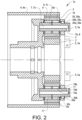
- Figure 2 schematically shows a planetary gearset 1 comprising a gear arrangement 1a comprising:
- the advantage of the gearset is that the planet carrier is free from channels, which makes it possible to manufacture a solid small/thin and lightweight planet carrier.
- the planet carrier 10 comprises an inside surface 10a facing the planet gears 3 and an outside surface 10b facing away from the planet gears 3.
- the protruding portion 5a protrudes out from the outside surface 10b of the planet carrier 10.
- Figure 2 schematically shows that the planet gear shaft 5 is stored in the planet carrier 10 on either side of the planet gear 3.
- a first end of the planet gear shaft 5 is stored in the planet gear via the portion of the planet gear shaft 5 that extends through the planet carrier 10 and the second end can be stored in any suitable way.
- the second end is stored in an indentation in the planet carrier 5.
- the planetary gearset 1 comprises a locking member 30 arranged in connection to the planetary gear shaft 5 and the planet carrier 10 for locking the planet gear shaft 5 in a predetermined position in relation to the planet carrier 10.
- the locking member 30 comprises a locking pin 30a and a first indentation 30b in the planet gear shaft envelope surface 11 and a second indentation 30c in the planet carrier 10.
- the first and second indentations 30b, 30c are juxtapositioned each other and the locking pin 30a is positioned partly in both the first and second indentation 30b, 30c thereby hindering relative motion of the planetary gear shaft 5 in relation to the planet carrier 10.
- pin and indentations 30b, 30c are advantageously used indentations.
- the indentations can be arranged in a direction coinciding with the direction of insertion of the planetary gear shaft 5 into the planet carrier 10 and the locking pin 30a can be inserted into one of the indentations and then slid into position of the other indentation.
- Figure 2 shows that the planet carrier 10 comprises a through channel 10c per planetary gear shaft 5 extending from the inside surface 10a to the outside surface 10b. Each through channel 10c is arranged to house the planetary gear shaft 5 and is delimited by an inner wall 10d.
- Figure 2 shows that the second indentation 30c is arranged in the inner wall 10d and the second indentation 30c comprises an opening 30d in the inside surface 10a and an opening 30e in the outside surface 10b of the planet carrier 10 allowing for the locking pin 30a to enter the second indentation 30c via the openings.
- the second indentation 30c is furthermore arranged with an orientation coinciding with the travel direction of the planetary gear shaft 5 when inserted into the through channel 10c of the planet carrier 10.
- Figure 2 shows that the planet gear shaft channel 7 in the planet gear shaft 5 comprises an axially extending planet gear shaft main channel 7a and a planet gear shaft inlet channel 7b connecting the planet gear shaft main channel 7a to the inlet opening 8, wherein the inlet opening 8 is arranged radially in the planet gear shaft 5 envelope surface 11.
- the planet gear shaft inlet channel 7b can be arranged strictly in the radial direction as in figure 2 , i.e. perpendicular to the axial direction, or may be arranged at an angle to the axial direction.
- Figure 2 furthermore shows that the planet gear shaft channel 7 in the planet gear shaft 5 comprises an planet gear shaft outlet channel 7c connecting the planet gear shaft main channel 7a to the outlet opening 9, wherein the outlet opening 9 is arranged radially in the planet gear shaft envelope surface 11 and in connection to the planet gear bearing 6.
- the planet gear shaft outlet channel 7c can be arranged strictly in the radial direction as in figure 1 , i.e. perpendicular to the axial direction, or may be arranged at an angle to the axial direction.
- the planet gear shaft main channel 7a is arranged concentric in the planet gear shaft 5.
- the advantage is that the planet gear shaft 5 becomes stronger than a planet gear shaft 5 with different wall thickness.
- Figure 2 further schematically shows that the planetary gearset 1 comprises axial washers and/or bearings, hereinafter called planet gear thrust bearings 6b, arranged between the planet gear 3 and the planet carrier 10 and around the planet gear shaft 5 to allow for relative motion of the planetary gears 3 with relation to the planet carrier 10.
- the planet gear shaft channel 7 with inlet opening 8 and an outlet opening 9 allows for feeding of the lubricant also to the planet gear thrust bearings 6b.
- Figure 3 schematically shows that the planetary gearset 1 comprises a lubricant feed unit in the form of a clutch cylinder 12 attached to the planet carrier 10 via bolts 102.
- the clutch cylinder 12 is fixedly attached to the planet carrier 10 and follows the motion of the planet carrier 10, i.e. rotates or is stationary.
- the clutch cylinder 12 comprises an annular extension 13 extending in the axial direction.
- axial direction coincides with axial direction of the planet gear shaft 5 when mounted into the through channel 10c of the planet carrier 10.
- the annular extension 13 comprises feed channels 14, each feed channel 14 comprising a feed channel inlet opening 15 and a feed channel outlet opening 16 arranged to coincide with the inlet opening 8 of the planet gear shaft channel 7 for fluid communication of a lubricant from the annular extension 13 to the planet gear shaft channel 7.
- Each feed channel 14 has a main extension in the axial direction and the feed channel outlet opening 16 faces in the radial direction towards the inlet opening 8 of the planet gear shaft channel 7.
- Figure 3 shows that the annular extension 13 comprises a receiving portion 17 adapted to be attached to the protruding portion 5a of the planet gear shaft 5, wherein the receiving portion 17 comprises the feed channel outlet opening 16 coinciding with the inlet opening 8 of the planet gear shaft 5.
- the receiving portion 17 is formed to fit the size, form and length of the protruding portion 5a.
- the receiving portion could be arranged with a snug fit or with a play between the receiving portion and the protruding portion creating a channel that allows the lubricant to flow from the feed channel outlet opening to the inlet opening of the planet gear shaft.
- Sealing elements can be arranged between the planet gear shaft and the receiving portion to hinder the lubricant from leaking out towards the planet carrier.
- One advantage with this arrangement is that the feed channel outlet opening does not have to match, i.e. coincide, entirely with the inlet opening of the planet gear shaft to ensure fluid communication of the lubricant
- Figures 3-5 shows that the feed channel 14 comprises an angled portion 14a and a main feed channel 14b extending in the axial direction.
- the angled portion 14a is arranged between the feed channel outlet opening 16 and the main feed channel 14b.
- the angled portion has the advantage of easy manufacture since the feed channel outlet opening 16 can be drilled open together with the angled portion with use of a drill working at an angle in the receiving portion 17.
- the main feed channel 14b can be created by a first drill operation from the feed channel inlet opening 15 side and then be connected to the angled portion by a second drill operation creating the angled portion 14a and the feed channel outlet opening 16 from the feed channel outlet opening 16 side.
- Figure 4 schematically shows the planetary gearset 1 according to the invention, which comprises an intermediate wall 18 comprising an annular recess 19 having a bottom wall 20 and two therefrom axially extending sidewalls 21, wherein the sidewalls 21 form a bearing race way for the annular extension 13, and wherein the bottom wall 20 is arranged at a distance from the annular extension 13 forming an annular distribution channel 22 between the bottom wall 20 and the annular extension 13 for feeding the lubricant from the intermediate wall 18 to the feed channel inlet openings 15 in the annular extension 13.
- Figure 4 schematically shows that the planetary gearset 1 comprises an annular seal element 23 arranged between the respective sidewalls 21 and the annular extension 13, wherein the annular seal element 23 is arranged to seal between the sidewalls 21 and the annular extension 13.
- the annular seal element 23 is arranged to allow for movement of the clutch cylinder 12, and thus the annular extension 13, in relation to the intermediate wall such that the lubricant is sealed from leaking out from the annular recess 19 between the annular extension 13 and the axially extending sidewalls 21.
- Figure 4 schematically shows that the intermediate wall 18 comprises an intermediate wall channel 18a comprising an intermediate wall inlet opening 28 and an intermediate wall outlet opening 18b in fluid communication with the annular distribution channel 22.
- the intermediate wall channel 18a is arranged in the intermediate wall 18 essentially in the radial direction with the purpose of feeding lubricants to the annular distribution channel 22.
- Figure 4 shows that the intermediate wall channel 18a comprises one intermediate wall outlet opening 18b in fluid communication with the annular distribution channel 22.
- the intermediate wall channel 18a comprises several intermediate wall outlet opening 18b.
- the intermediate wall channel 18a can be arranged as one straight channel or an annularly extending channel as in figure 4 or as a network of channels with a number of intermediate wall outlet opening 18b.
- the intermediate wall outlet openings 18b are arranged with an extension in the axial direction to connect to the intermediate wall channel 18a.
- Figure 5 shows that the planetary gearset 1, according to the invention, comprises a stationary transmission housing 24 at least partly encompassing the gear arrangement 1a and wherein the intermediate wall 18 is attached to the transmission housing 24.
- the stationary transmission housing 24 comprises a base channel 25 with a base channel outlet opening 26 and a base channel inlet opening 27, wherein the base channel outlet opening 26 is arranged to coincide with the intermediate wall inlet opening 28, and wherein the base channel inlet opening 27 is connectable to a lubricant feed source 29.
- the base channel 25 is arranged to distribute lubricants from the feed source to the intermediate wall channel 18a.
- the feed source 28 may be arranged to apply pressure to the lubricating medium such that the entire system of channels are set under pressure for delivery of the lubricant to the planet gear bearings.
- Figure 5 shows that the lubricant feed source 29 is connected to a control unit 31 arranged to control the distribution of lubricants to the channel system, for example by regulating the pressure of the lubricant in the channel system.
- control unit 31 arranged to control the distribution of lubricants to the channel system, for example by regulating the pressure of the lubricant in the channel system.
- channel system refers to the channels described in connection to figures 2-5 .
- the planet carrier 10 is arranged to be selectively stationary or rotatable in order to allow for a full range of speeds ratios between an input shaft and an output shaft and according to the invention the planet gear bearings are lubricated also when the planet carrier is stationary.
- the planet gear shaft comprises a plurality of planet gear shaft inlet channels and corresponding inlet openings and/or a plurality of planet gear shaft outlet channels and corresponding outlet openings.
- One advantage is the possibility to increase the flow of lubricant.
- One advantage with a plurality of planet gear shaft outlet channels and corresponding outlet openings is an increased spread of lubricant towards the planet gear bearings.
- a plurality of feed channels is possible to increase fluid flow.
Claims (13)
- Train d'engrenages planétaires (1) comprenant un système d'engrenages (1a) comprenant :- un engrenage solaire disposé au centre (2) conçu pour être fixé de manière à pouvoir tourner à un arbre d'entraînement (101),- un train d'engrenages planétaires (3) répartis circonférentiellement autour et en engrènement avec l'engrenage solaire (2),- un élément d'engrenage annulaire (4) s'étendant circonférentiellement autour des engrenages planétaires (3) et étant pourvu d'un engrenage annulaire (4a) s'engrenant avec les engrenages planétaires (3),- un ensemble d'arbres d'engrenages planétaires (5), chacun étant disposé au centre de et connectée à un engrenage planétaire correspondant (3),- un ensemble de palier d'engrenage planétaire (6), chacun étant disposé entre un arbre d'engrenage planétaire correspondant (5) et son engrenage planétaire correspondant (3) pour connecter de manière à pouvoir tourner l'engrenage planétaire (3) à l'arbre d'engrenage planétaire (5),- chaque arbre d'engrenage planétaire (5) comprenant un canal d'arbre d'engrenage planétaire (7) doté d'une ouverture d'entrée (8) et d'une ouverture de sortie (9) pour apporter un lubrifiant dans le palier d'engrenage planétaire (6),- un support planétaire (10) connectée au train d'engrenages planétaires (3) via les arbres d'engrenages planétaires (5),chaque arbre d'engrenage planétaire (5) s'étendant dans un sens axial depuis l'engrenage planétaire (3) à travers le support planétaire (10) et comprenant une section saillante (5a) qui dépasse du support planétaire (10) sur une face opposée du support planétaire (10) par rapport à l'engrenage planétaire (3), la section saillante (5a) comprenant l'ouverture d'entrée (8), le train d'engrenages planétaires (1) comprenant un élément de verrouillage (30) disposé en connexion avec l'arbre d'engrenage planétaire (5) et le support planétaire (10) pour verrouiller l'arbre d'engrenage planétaire (5) dans une position prédéterminée par rapport au support planétaire (10), caractérisé en ce que le train d'engrenages planétaires (1) comprend une unité d'alimentation en lubrifiant (12) fixée au support planétaire (10), l'unité d'alimentation en lubrifiant (12) comprenant une extension annulaire (13) s'étendant dans le sens axial, l'extension annulaire (13) comprenant des canaux d'alimentation (14), chaque canal d'alimentation (14) comprenant une ouverture d'entrée de canal d'alimentation (15) et une ouverture de sortie de canal d'alimentation (16) disposée de manière à coïncider avec l'ouverture d'entrée de canal d'arbre d'engrenage planétaire (8) pour la communication fluidique d'un lubrifiant depuis l'extension annulaire (13) jusqu'au canal d'arbre d'engrenages planétaires (7),le train d'engrenages planétaires (1) comprenant une paroi intermédiaire (18) comprenant un retrait annulaire (19) doté d'une paroi inférieure (20) et de deux parois latérales (21) s'étendant axialement depuis là, les parois latérales (21) formant une piste support pour l'extension annulaire (13), la paroi inférieure (20) étant disposée à distance de l'extension annulaire (13) formant un canal de distribution annulaire (22) entre la paroi inférieure (20) et l'extension annulaire (13) pour apporter le lubrifiant depuis la paroi intermédiaire (18) jusqu'aux ouvertures d'entrée de canal d'alimentation (15) dans l'extension annulaire (13) .
- Train d'engrenages planétaires (1) selon la revendication 1, dans lequel le canal d'arbre d'engrenage planétaire (7) comprend un canal principal d'arbre d'engrenage planétaire s'étendant axialement connectant le canal principal d'arbre d'engrenage planétaire (7a) s'étendant axialement et un canal d'entrée d'arbre d'engrenages planétaires (7b) connectant le canal principal d'arbre d'engrenages planétaires (7a) à l'ouverture d'entrée (8), l'ouverture d'entrée (8) étant disposée tournée dans le sens radial dans une surface extérieure d'arbre d'engrenage planétaire (11).
- Train d'engrenages planétaires (1) selon la revendication 2, dans lequel le canal d'arbre d'engrenage planétaire (7) comprend un canal de sortie d'arbre d'engrenage planétaire (7c) connectant le canal principal d'arbre d'engrenage planétaire (7a) à l'ouverture de sortie (9), l'ouverture de sortie (9) étant disposée tournée dans le sens radial dans la surface extérieure d'arbre d'engrenage planétaire et en connexion avec le palier d'engrenage planétaire (6).
- Train d'engrenages planétaires (1) selon la revendication 2 ou 3, dans lequel le canal principal d'arbre d'engrenages planétaires (7a) est disposé concentriquement dans l'arbre d'engrenage planétaire (5) .
- Train d'engrenages planétaires (1) selon l'une quelconque des revendications précédentes, dans lequel l'extension annulaire (13) comprend une section de réception (17) apte à être fixée à la section saillante (5a) de l'arbre d'engrenage planétaire (5), la section de réception (17) comprenant l'ouverture de sortie de canal d'alimentation (16) coïncidant avec l'ouverture d'entrée (8) de l'arbre d'engrenage planétaire (5).
- Train d'engrenages planétaires (1) selon l'une quelconque des revendications précédentes, dans lequel le train d'engrenages planétaires (1) comprend un élément d'étanchéité annulaire (23) disposé entre les parois latérales respectives (21) et l'extension annulaire (13), l'élément d'étanchéité annulaire (23) étant conçu pour établir une étanchéité entre les parois latérales (21) et l'extension annulaire (13).
- Train d'engrenages planétaires (1) selon l'une quelconque des revendications précédentes, dans lequel la paroi intermédiaire (18) comprend un canal de paroi intermédiaire (18a) comprenant une ouverture d'entrée de paroi intermédiaire (28) et une ouverture de sortie de paroi intermédiaire (18b) en communication fluidique avec le canal de distribution annulaire (22).
- Train d'engrenages planétaires (1) selon l'une quelconque des revendications précédentes, dans lequel l'unité d'alimentation en lubrifiant (12) se présente sous la forme d'un cylindre d'embrayage (12) fixé au support planétaire (10).
- Train d'engrenages planétaires (1) selon l'une quelconque des revendications précédentes, dans lequel le train d'engrenages planétaires (1) comprend un boîtier de transmission stationnaire (24) renfermant au moins partiellement le système d'engrenages (1a) et la paroi intermédiaire (18) est fixée au boîtier de transmission (24).
- Train d'engrenages planétaires (1) selon la revendication 9, dans lequel le boîtier de transmission stationnaire (24) comprend un canal de base (25) doté d'une ouverture de sortie de canal de base (26) et d'une ouverture d'entrée de canal de base (27), l'ouverture de sortie de canal de base (26) étant disposée de manière à coïncider avec l'ouverture d'entrée de paroi intermédiaire (28), et l'ouverture d'entrée de canal de base (27) étant connectable à une source d'alimentation en lubrifiant (28).
- Train d'engrenages planétaires (1) selon l'une quelconque des revendications précédentes, dans lequel le canal d'alimentation (14) comprend une section coudée (14a).
- Train d'engrenages planétaires (1) selon l'une quelconque des revendications précédentes, dans lequel le support planétaire (10) est conçu pour être sélectivement stationnaire ou rotatif.
- Véhicule ou unité stationnaire comprenant un train d'engrenages planétaires (1) selon l'une quelconque des revendications 1 à 12.
Applications Claiming Priority (1)
| Application Number | Priority Date | Filing Date | Title |
|---|---|---|---|
| PCT/EP2018/074786 WO2020052768A1 (fr) | 2018-09-13 | 2018-09-13 | Train planétaire et véhicule ou unité fixe comprenant un tel train d'engrenages |
Publications (3)
| Publication Number | Publication Date |
|---|---|
| EP3850247A1 EP3850247A1 (fr) | 2021-07-21 |
| EP3850247B1 true EP3850247B1 (fr) | 2023-06-07 |
| EP3850247C0 EP3850247C0 (fr) | 2023-06-07 |
Family
ID=63708288
Family Applications (1)
| Application Number | Title | Priority Date | Filing Date |
|---|---|---|---|
| EP18779238.7A Active EP3850247B1 (fr) | 2018-09-13 | 2018-09-13 | Train planétaire et véhicule ou unité fixe comprenant un tel train d'engrenages |
Country Status (4)
| Country | Link |
|---|---|
| US (1) | US11879538B2 (fr) |
| EP (1) | EP3850247B1 (fr) |
| CN (1) | CN112673196B (fr) |
| WO (1) | WO2020052768A1 (fr) |
Families Citing this family (1)
| Publication number | Priority date | Publication date | Assignee | Title |
|---|---|---|---|---|
| DE102021207527A1 (de) | 2021-07-15 | 2023-01-19 | Zf Friedrichshafen Ag | Getriebe für ein integrales Differential, integrales Differential sowie Antriebsstrang |
Family Cites Families (11)
| Publication number | Priority date | Publication date | Assignee | Title |
|---|---|---|---|---|
| DE10309666A1 (de) * | 2003-03-06 | 2004-12-09 | Ina-Schaeffler Kg | Lagefixierung eines Planetenradbolzens |
| US20060068961A1 (en) | 2004-09-28 | 2006-03-30 | Haka Raymond J | Lubricating apparatus in a planetary gearset |
| US8343002B1 (en) * | 2011-06-20 | 2013-01-01 | GM Global Technology Operations LLC | Rotating planetary gear carrier lubrication device |
| FR2987416B1 (fr) * | 2012-02-23 | 2015-09-04 | Snecma | Dispositif de lubrification d'un reducteur epicycloidal. |
| US9879608B2 (en) * | 2014-03-17 | 2018-01-30 | United Technologies Corporation | Oil loss protection for a fan drive gear system |
| US9512900B2 (en) * | 2015-05-08 | 2016-12-06 | E-Aam Driveline Systems Ab | Planetary gear mechanism with reduced gear lash |
| JP6498559B2 (ja) * | 2015-07-31 | 2019-04-10 | 川崎重工業株式会社 | 遊星歯車装置への給油構造 |
| US20170152937A1 (en) * | 2015-11-30 | 2017-06-01 | Caterpillar Inc. | Machine Having an Electrical Power System that Includes a Planetary Gear System |
| US9803742B1 (en) * | 2016-07-18 | 2017-10-31 | GM Global Technology Operations LLC | Stacked planetary gear assembly with improved lubrication |
| DE102016220487A1 (de) | 2016-10-19 | 2018-04-19 | Robert Bosch Gmbh | Planetengetriebe und Antriebseinheit |
| US10662879B2 (en) * | 2017-08-08 | 2020-05-26 | Pratt & Whitney Canada Corp. | Epicyclic gear stage |
-
2018
- 2018-09-13 US US17/275,394 patent/US11879538B2/en active Active
- 2018-09-13 CN CN201880097431.0A patent/CN112673196B/zh active Active
- 2018-09-13 WO PCT/EP2018/074786 patent/WO2020052768A1/fr unknown
- 2018-09-13 EP EP18779238.7A patent/EP3850247B1/fr active Active
Also Published As
| Publication number | Publication date |
|---|---|
| US20220056994A1 (en) | 2022-02-24 |
| US11879538B2 (en) | 2024-01-23 |
| CN112673196B (zh) | 2024-02-20 |
| EP3850247C0 (fr) | 2023-06-07 |
| WO2020052768A1 (fr) | 2020-03-19 |
| EP3850247A1 (fr) | 2021-07-21 |
| CN112673196A (zh) | 2021-04-16 |
Similar Documents
| Publication | Publication Date | Title |
|---|---|---|
| EP1488139B1 (fr) | Lubrification d'entrainement par engrenages | |
| US3821908A (en) | Retainer for planet pinion shaft | |
| JP4747708B2 (ja) | 車両用自動変速機 | |
| CN107631014B (zh) | 具有改进润滑的堆叠行星齿轮组件 | |
| EP2045487A2 (fr) | Transmission automatique et son procédé de lubrification | |
| US6890280B2 (en) | Lubricating device for automatic power transmission | |
| CN100462596C (zh) | 用于自动变速器的活塞 | |
| US9382997B2 (en) | Gear set lubrication system and method | |
| CN115875425B (zh) | 一种内齿圈轴、输入轴总成、混合动力电驱动总成及车辆 | |
| US20120279327A1 (en) | Final drive mechanism and power take off for a transmission | |
| EP3850247B1 (fr) | Train planétaire et véhicule ou unité fixe comprenant un tel train d'engrenages | |
| US8475325B2 (en) | Gearset carrier and servo cylinder assembly | |
| US8454468B2 (en) | Clutch piston support | |
| US8702553B2 (en) | Transfer shaft support | |
| US20120220408A1 (en) | Mechanism for Controlling a Transmission Component | |
| US8403788B2 (en) | Front support for transmission gear box | |
| JP2007024234A (ja) | 変速機の潤滑装置 | |
| US8844695B2 (en) | Carrying fluid to balance dams in a servo piston support | |
| US8544628B2 (en) | Pressure and flow continuity through transmission supports | |
| US8403798B2 (en) | Final drive mechanism for a transmission | |
| CN110725864A (zh) | 机械组件和机械装置 | |
| US11708888B2 (en) | Shaft for a motor vehicle transmission | |
| US9605747B2 (en) | Control element discs splined to raceways of a one-way control element | |
| CN212804170U (zh) | 无级变速拖拉机复式差动行星机构的润滑结构 | |
| CN210118439U (zh) | 变速箱和车辆 |
Legal Events
| Date | Code | Title | Description |
|---|---|---|---|
| STAA | Information on the status of an ep patent application or granted ep patent |
Free format text: STATUS: UNKNOWN |
|
| STAA | Information on the status of an ep patent application or granted ep patent |
Free format text: STATUS: THE INTERNATIONAL PUBLICATION HAS BEEN MADE |
|
| PUAI | Public reference made under article 153(3) epc to a published international application that has entered the european phase |
Free format text: ORIGINAL CODE: 0009012 |
|
| STAA | Information on the status of an ep patent application or granted ep patent |
Free format text: STATUS: REQUEST FOR EXAMINATION WAS MADE |
|
| 17P | Request for examination filed |
Effective date: 20210311 |
|
| AK | Designated contracting states |
Kind code of ref document: A1 Designated state(s): AL AT BE BG CH CY CZ DE DK EE ES FI FR GB GR HR HU IE IS IT LI LT LU LV MC MK MT NL NO PL PT RO RS SE SI SK SM TR |
|
| DAV | Request for validation of the european patent (deleted) | ||
| DAX | Request for extension of the european patent (deleted) | ||
| GRAP | Despatch of communication of intention to grant a patent |
Free format text: ORIGINAL CODE: EPIDOSNIGR1 |
|
| STAA | Information on the status of an ep patent application or granted ep patent |
Free format text: STATUS: GRANT OF PATENT IS INTENDED |
|
| INTG | Intention to grant announced |
Effective date: 20221031 |
|
| GRAS | Grant fee paid |
Free format text: ORIGINAL CODE: EPIDOSNIGR3 |
|
| GRAA | (expected) grant |
Free format text: ORIGINAL CODE: 0009210 |
|
| STAA | Information on the status of an ep patent application or granted ep patent |
Free format text: STATUS: THE PATENT HAS BEEN GRANTED |
|
| AK | Designated contracting states |
Kind code of ref document: B1 Designated state(s): AL AT BE BG CH CY CZ DE DK EE ES FI FR GB GR HR HU IE IS IT LI LT LU LV MC MK MT NL NO PL PT RO RS SE SI SK SM TR |
|
| REG | Reference to a national code |
Ref country code: GB Ref legal event code: FG4D |
|
| REG | Reference to a national code |
Ref country code: CH Ref legal event code: EP Ref country code: AT Ref legal event code: REF Ref document number: 1575977 Country of ref document: AT Kind code of ref document: T Effective date: 20230615 Ref country code: DE Ref legal event code: R096 Ref document number: 602018051215 Country of ref document: DE |
|
| U01 | Request for unitary effect filed |
Effective date: 20230607 |
|
| U07 | Unitary effect registered |
Designated state(s): AT BE BG DE DK EE FI FR IT LT LU LV MT NL PT SE SI Effective date: 20230612 |
|
| U1B | Unitary effect: place of business changed | ||
| REG | Reference to a national code |
Ref country code: LT Ref legal event code: MG9D |
|
| PG25 | Lapsed in a contracting state [announced via postgrant information from national office to epo] |
Ref country code: NO Free format text: LAPSE BECAUSE OF FAILURE TO SUBMIT A TRANSLATION OF THE DESCRIPTION OR TO PAY THE FEE WITHIN THE PRESCRIBED TIME-LIMIT Effective date: 20230907 Ref country code: ES Free format text: LAPSE BECAUSE OF FAILURE TO SUBMIT A TRANSLATION OF THE DESCRIPTION OR TO PAY THE FEE WITHIN THE PRESCRIBED TIME-LIMIT Effective date: 20230607 |
|
| PGFP | Annual fee paid to national office [announced via postgrant information from national office to epo] |
Ref country code: GB Payment date: 20230926 Year of fee payment: 6 |
|
| U20 | Renewal fee paid [unitary effect] |
Year of fee payment: 6 Effective date: 20230926 |
|
| PG25 | Lapsed in a contracting state [announced via postgrant information from national office to epo] |
Ref country code: RS Free format text: LAPSE BECAUSE OF FAILURE TO SUBMIT A TRANSLATION OF THE DESCRIPTION OR TO PAY THE FEE WITHIN THE PRESCRIBED TIME-LIMIT Effective date: 20230607 Ref country code: HR Free format text: LAPSE BECAUSE OF FAILURE TO SUBMIT A TRANSLATION OF THE DESCRIPTION OR TO PAY THE FEE WITHIN THE PRESCRIBED TIME-LIMIT Effective date: 20230607 Ref country code: GR Free format text: LAPSE BECAUSE OF FAILURE TO SUBMIT A TRANSLATION OF THE DESCRIPTION OR TO PAY THE FEE WITHIN THE PRESCRIBED TIME-LIMIT Effective date: 20230908 |
|
| PG25 | Lapsed in a contracting state [announced via postgrant information from national office to epo] |
Ref country code: SK Free format text: LAPSE BECAUSE OF FAILURE TO SUBMIT A TRANSLATION OF THE DESCRIPTION OR TO PAY THE FEE WITHIN THE PRESCRIBED TIME-LIMIT Effective date: 20230607 |
|
| PG25 | Lapsed in a contracting state [announced via postgrant information from national office to epo] |
Ref country code: IS Free format text: LAPSE BECAUSE OF FAILURE TO SUBMIT A TRANSLATION OF THE DESCRIPTION OR TO PAY THE FEE WITHIN THE PRESCRIBED TIME-LIMIT Effective date: 20231007 |
|
| PG25 | Lapsed in a contracting state [announced via postgrant information from national office to epo] |
Ref country code: SM Free format text: LAPSE BECAUSE OF FAILURE TO SUBMIT A TRANSLATION OF THE DESCRIPTION OR TO PAY THE FEE WITHIN THE PRESCRIBED TIME-LIMIT Effective date: 20230607 Ref country code: SK Free format text: LAPSE BECAUSE OF FAILURE TO SUBMIT A TRANSLATION OF THE DESCRIPTION OR TO PAY THE FEE WITHIN THE PRESCRIBED TIME-LIMIT Effective date: 20230607 Ref country code: RO Free format text: LAPSE BECAUSE OF FAILURE TO SUBMIT A TRANSLATION OF THE DESCRIPTION OR TO PAY THE FEE WITHIN THE PRESCRIBED TIME-LIMIT Effective date: 20230607 Ref country code: IS Free format text: LAPSE BECAUSE OF FAILURE TO SUBMIT A TRANSLATION OF THE DESCRIPTION OR TO PAY THE FEE WITHIN THE PRESCRIBED TIME-LIMIT Effective date: 20231007 Ref country code: CZ Free format text: LAPSE BECAUSE OF FAILURE TO SUBMIT A TRANSLATION OF THE DESCRIPTION OR TO PAY THE FEE WITHIN THE PRESCRIBED TIME-LIMIT Effective date: 20230607 |
|
| PG25 | Lapsed in a contracting state [announced via postgrant information from national office to epo] |
Ref country code: PL Free format text: LAPSE BECAUSE OF FAILURE TO SUBMIT A TRANSLATION OF THE DESCRIPTION OR TO PAY THE FEE WITHIN THE PRESCRIBED TIME-LIMIT Effective date: 20230607 |
|
| REG | Reference to a national code |
Ref country code: DE Ref legal event code: R097 Ref document number: 602018051215 Country of ref document: DE |
|
| PLBE | No opposition filed within time limit |
Free format text: ORIGINAL CODE: 0009261 |
|
| STAA | Information on the status of an ep patent application or granted ep patent |
Free format text: STATUS: NO OPPOSITION FILED WITHIN TIME LIMIT |
|
| REG | Reference to a national code |
Ref country code: CH Ref legal event code: PL |