EP3849291A1 - Schaltungshaltesysteme - Google Patents
Schaltungshaltesysteme Download PDFInfo
- Publication number
- EP3849291A1 EP3849291A1 EP21150502.9A EP21150502A EP3849291A1 EP 3849291 A1 EP3849291 A1 EP 3849291A1 EP 21150502 A EP21150502 A EP 21150502A EP 3849291 A1 EP3849291 A1 EP 3849291A1
- Authority
- EP
- European Patent Office
- Prior art keywords
- pressure
- retainer
- circuit board
- contact
- circuit
- Prior art date
- Legal status (The legal status is an assumption and is not a legal conclusion. Google has not performed a legal analysis and makes no representation as to the accuracy of the status listed.)
- Granted
Links
Images


Classifications
-
- G—PHYSICS
- G01—MEASURING; TESTING
- G01M—TESTING STATIC OR DYNAMIC BALANCE OF MACHINES OR STRUCTURES; TESTING OF STRUCTURES OR APPARATUS, NOT OTHERWISE PROVIDED FOR
- G01M13/00—Testing of machine parts
-
- G—PHYSICS
- G01—MEASURING; TESTING
- G01L—MEASURING FORCE, STRESS, TORQUE, WORK, MECHANICAL POWER, MECHANICAL EFFICIENCY, OR FLUID PRESSURE
- G01L5/00—Apparatus for, or methods of, measuring force, work, mechanical power, or torque, specially adapted for specific purposes
- G01L5/0028—Force sensors associated with force applying means
-
- H—ELECTRICITY
- H05—ELECTRIC TECHNIQUES NOT OTHERWISE PROVIDED FOR
- H05K—PRINTED CIRCUITS; CASINGS OR CONSTRUCTIONAL DETAILS OF ELECTRIC APPARATUS; MANUFACTURE OF ASSEMBLAGES OF ELECTRICAL COMPONENTS
- H05K7/00—Constructional details common to different types of electric apparatus
- H05K7/14—Mounting supporting structure in casing or on frame or rack
-
- H—ELECTRICITY
- H05—ELECTRIC TECHNIQUES NOT OTHERWISE PROVIDED FOR
- H05K—PRINTED CIRCUITS; CASINGS OR CONSTRUCTIONAL DETAILS OF ELECTRIC APPARATUS; MANUFACTURE OF ASSEMBLAGES OF ELECTRICAL COMPONENTS
- H05K7/00—Constructional details common to different types of electric apparatus
- H05K7/14—Mounting supporting structure in casing or on frame or rack
- H05K7/1401—Mounting supporting structure in casing or on frame or rack comprising clamping or extracting means
-
- H—ELECTRICITY
- H05—ELECTRIC TECHNIQUES NOT OTHERWISE PROVIDED FOR
- H05K—PRINTED CIRCUITS; CASINGS OR CONSTRUCTIONAL DETAILS OF ELECTRIC APPARATUS; MANUFACTURE OF ASSEMBLAGES OF ELECTRICAL COMPONENTS
- H05K7/00—Constructional details common to different types of electric apparatus
- H05K7/14—Mounting supporting structure in casing or on frame or rack
- H05K7/1401—Mounting supporting structure in casing or on frame or rack comprising clamping or extracting means
- H05K7/1402—Mounting supporting structure in casing or on frame or rack comprising clamping or extracting means for securing or extracting printed circuit boards
- H05K7/1404—Mounting supporting structure in casing or on frame or rack comprising clamping or extracting means for securing or extracting printed circuit boards by edge clamping, e.g. wedges
-
- H—ELECTRICITY
- H05—ELECTRIC TECHNIQUES NOT OTHERWISE PROVIDED FOR
- H05K—PRINTED CIRCUITS; CASINGS OR CONSTRUCTIONAL DETAILS OF ELECTRIC APPARATUS; MANUFACTURE OF ASSEMBLAGES OF ELECTRICAL COMPONENTS
- H05K7/00—Constructional details common to different types of electric apparatus
- H05K7/14—Mounting supporting structure in casing or on frame or rack
- H05K7/1401—Mounting supporting structure in casing or on frame or rack comprising clamping or extracting means
- H05K7/1402—Mounting supporting structure in casing or on frame or rack comprising clamping or extracting means for securing or extracting printed circuit boards
- H05K7/1409—Mounting supporting structure in casing or on frame or rack comprising clamping or extracting means for securing or extracting printed circuit boards by lever-type mechanisms
-
- H—ELECTRICITY
- H05—ELECTRIC TECHNIQUES NOT OTHERWISE PROVIDED FOR
- H05K—PRINTED CIRCUITS; CASINGS OR CONSTRUCTIONAL DETAILS OF ELECTRIC APPARATUS; MANUFACTURE OF ASSEMBLAGES OF ELECTRICAL COMPONENTS
- H05K7/00—Constructional details common to different types of electric apparatus
- H05K7/14—Mounting supporting structure in casing or on frame or rack
- H05K7/1417—Mounting supporting structure in casing or on frame or rack having securing means for mounting boards, plates or wiring boards
Definitions
- circuit systems e.g., circuit retainer systems therefor.
- wedge locks e.g., for retaining circuit cards
- LRU line replaceable unit
- a circuit retaining system includes a contact monitoring system configured to determine if a retainer is providing at least predetermined pressure to a circuit board when the retainer is retaining the circuit board.
- the contact monitoring system can include a pressure sensor configured to be disposed between the retainer and the circuit board and to output a pressure sensor signal indicating a contact pressure.
- the contact monitoring system can include a monitor module configured to receive the pressure sensor signal and to determine if a contact pressure is at least the predetermined pressure.
- the monitor module can be configured to output a monitor state when the contact pressure is at least the predetermined pressure.
- the monitor module can include any suitable hardware module(s) and/or software module(s) configured to perform any suitable function, e.g., disclosed herein.
- the predetermined pressure can be a contact pressure at or above a threshold pressure.
- the predetermined pressure can be a contact pressure at or below a threshold pressure.
- the contact monitoring system can include an indicator configured to receive the monitor state and to indicate that the monitor module is outputting the monitor state.
- the indicator can be an LED, for example.
- the indicator can be a display configured to display a pressure value of the contact pressure. Any other suitable indicator(s) (e.g., a display) and/or combinations thereof are contemplated herein.
- the circuit retaining system can include the retainer configured to retain the circuit board.
- the contact monitoring system can be disposed on the retainer.
- circuit retaining system can include the circuit board.
- the contact monitoring system can be disposed on the circuit board.
- the retainer can be a wedge lock retainer.
- the pressure sensor can be disposed between a wedge of the wedge lock retainer and the circuit board.
- the pressure sensor can be connected to the wedge of the wedge lock retainer.
- a circuit assembly includes a circuit board, a retainer configured to retainer the circuit board, and a circuit retaining system as disclosed herein, e.g., as described above. Any suitable circuit retaining system in accordance with this disclosure is contemplated herein.
- a method includes monitoring a pressure sensor to determine if a contact pressure between a retainer and a circuit board is a predetermined value or within a predetermined range of values, and activating or deactivating an indicator if the contact pressure is of the predetermined value or within the predetermined range of values.
- activating or deactivating the indicator can include turning on an LED or turning of an LED when the contact pressure is of the predetermined value or within the predetermined range of values.
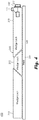
- FIG. 1 an illustrative view of an embodiment of a system in accordance with the disclosure is shown in Fig. 1 and is designated generally by reference character 100.
- FIGs. 2 and 3 Other embodiments and/or aspects of this disclosure are shown in Figs. 2 and 3 .
- Certain embodiments described herein can be used to determine if a circuit card is sufficiently retained (e.g., in a circuit assembly that the circuit card inserts into).
- a circuit retaining system 100 can include a contact monitoring system 101 configured to determine if a retainer 203 is providing at least predetermined pressure to a circuit board 205 when the retainer 203 is retaining the circuit board 205 (e.g., in electrical and/or thermal engagement with a receiving circuit board, not shown).
- the contact monitoring system 101 can include a pressure sensor 107 configured to be disposed between the retainer 203 and the circuit board 205 and to output a pressure sensor signal indicating a contact pressure (e.g., between the retainer 203 and the circuit board 205).
- the contact monitoring system 101 can include a monitor module 109 configured to receive the pressure sensor signal and to determine if a contact pressure is at least the predetermined pressure.
- the monitor module 109 can be configured to output a monitor state (e.g., a monitor signal or lack thereof) when the contact pressure is at least the predetermined pressure. Any other suitable pressure(s) to output the monitor state is contemplated herein.
- the monitor module 109 can include any suitable hardware module(s) and/or software module(s) configured to perform any suitable function, e.g., disclosed herein.
- the predetermined pressure can be a contact pressure at or above a threshold pressure. For example, if the pressure is at or above the threshold, the monitor module 109 can output the monitor state. In certain embodiments, the predetermined pressure can be a contact pressure at or below a threshold pressure. For example, in such embodiments, if the pressure is at or below the threshold, the monitor module 109 can output the monitor state. Any other suitable logic or combination thereof (e.g., having a high threshold and a low threshold to indicate pressure within a range) is contemplated herein.
- the contact monitoring system 101 can include an indicator 111 configured to receive the monitor state (e.g., a signal or lack thereof) and to indicate that the monitor module 109 is outputting the monitor state.
- the indicator 111 can be an LED, for example.
- the indicator 111 can be a display configured to display a pressure value of the contact pressure. Any other suitable indicator(s) (e.g., a display, an audible indicator, a tactile indicator) and/or combinations thereof are contemplated herein.
- the contact monitoring system 101 can include any other suitable components desired.
- the contact monitoring system 101 can include a battery and/or any other suitable power supply system configured to provide power to the monitor module 109 and/or the indicator 111.
- the circuit retaining system 100 can include the retainer 203 configured to retain the circuit board 205.
- the contact monitoring system 100 can be disposed on the retainer, e.g., as shown in assembly 200 of Fig. 2 .
- the retainer 203 can be a wedge lock retainer, e.g., as shown in Figs. 2 and 3 .
- the wedge lock retainer can include two or more axial drive members 213 configured to push against a wedge 215 to push the wedge 215 into the circuit board 205 when an axial screw 217 is turned to pull the axial drive members 213 together.
- Any suitable wedge lock or any other suitable retainer e.g., a swing bolt is contemplated herein.
- the pressure sensor 107 can be disposed between the wedge 215 of the wedge lock retainer and the circuit board 205, e.g., as shown.
- the pressure sensor 107 can be connected to the wedge 215 of the wedge lock retainer.
- the retainer 203 can include the monitor module 109 and the indicator 111 also attached thereto (e.g., connected to a surface of or within a component of the wedge lock).
- the indicator 111 can be disposed at an end of the axial drive member 213 at or near where the axial screw 217 is located, e.g., as shown, such that the indicator 111 is visible at least when the axial screw 217 is visible (e.g., which can allow sight of the indicator 111 in tight spaces).
- circuit retaining system 100 can include the circuit board 205, e.g., as shown in circuit assembly 300 of Fig. 3 .
- the contact monitoring system 101 can be disposed on the circuit board 205, for example.
- the monitoring module 109 can be integrated with the circuit board 205 such that it is a module of, part of a module, and/or hosted on a module of the circuit board 205.
- the indicator 111 can also be integrated with the circuit board 205, e.g., as shown, such that it is visible at an end of the circuit board 205. Any other suitable arrangement is contemplated herein.
- a circuit assembly e.g., 200, 300 as shown in Figs. 2 and 3 can include a circuit board 205, a retainer 203 configured to retainer the circuit board, and a circuit retaining system 100 as disclosed herein, e.g., as described above. Any suitable circuit retaining system in accordance with this disclosure is contemplated herein.
- a method can include monitoring a pressure sensor to determine if a contact pressure between a retainer and a circuit board is a predetermined value or within a predetermined range of values, and activating or deactivating an indicator if the contact pressure is of the predetermined value or within the predetermined range of values.
- activating or deactivating the indicator can include turning on an LED or turning of an LED when the contact pressure is of the predetermined value or within the predetermined range of values.
- Embodiments disclosed herein can provide wedge lock engagement sensing.
- embodiments can include a pressure sensor underneath a wedge lock or other retainer that gives reading of pressure when compressed, for example.
- embodiments can utilize pressure sensors to determine if the wedge locks or swing bolts are fully engaged.
- the pressure sensor and/or system can be integrated onto the retainer or the circuit board.
- the pressure sensor can be a circuit board component (e.g., a silicone die).
- Embodiments can include a monitor circuit for sensing pressure and determining if down pressure is sufficient.
- Sensor signals can be electrical feedback to a module (e.g., a processor) of the circuit board (e.g., an LRU) or used with a physical indicator, e.g., such as a visual or audible indictor.
- a module e.g., a processor
- the circuit board e.g., an LRU
- a physical indicator e.g., such as a visual or audible indictor.
- an indicator e.g., an LED can be turned off from an on state when enough pressure is present (e.g., a light can be turned on while installing until pressure is sufficient) and/or could read out pressure to a display for a user to visually see if pressure is high enough.
- the contact monitoring system can be entirely separate and attach to the retainer and/or the circuit board in the field.
- Embodiments can provide improved field reliability, user satisfaction, and fewer zero hour returns. Data from the pressure sensor can also be used for preventative health monitoring, for example.
- aspects of the present disclosure may be embodied as a system, method or computer program product. Accordingly, aspects of this disclosure may take the form of an entirely hardware embodiment, an entirely software embodiment (including firmware, resident software, micro-code, etc.), or an embodiment combining software and hardware aspects, all possibilities of which can be referred to herein as a "circuit,” “module,” or “system.”
- a “circuit,” “module,” or “system” can include one or more portions of one or more separate physical hardware and/or software components that can together perform the disclosed function of the "circuit,” “module,” or “system”, or a “circuit,” “module,” or “system” can be a single self-contained unit (e.g., of hardware and/or software).
- aspects of this disclosure may take the form of a computer program product embodied in one or more computer readable medium(s) having computer readable program code embodied thereon.
- the computer readable medium may be a computer readable signal medium or a computer readable storage medium.
- a computer readable storage medium may be, for example, but not limited to, an electronic, magnetic, optical, electromagnetic, infrared, or semiconductor system, apparatus, or device, or any suitable combination of the foregoing.
- a computer readable storage medium may be any tangible medium that can contain, or store a program for use by or in connection with an instruction execution system, apparatus, or device.
- a computer readable signal medium may include a propagated data signal with computer readable program code embodied therein, for example, in baseband or as part of a carrier wave. Such a propagated signal may take any of a variety of forms, including, but not limited to, electro-magnetic, optical, or any suitable combination thereof.
- a computer readable signal medium may be any computer readable medium that is not a computer readable storage medium and that can communicate, propagate, or transport a program for use by or in connection with an instruction execution system, apparatus, or device.
- Program code embodied on a computer readable medium may be transmitted using any appropriate medium, including but not limited to wireless, wireline, optical fiber cable, RF, etc., or any suitable combination of the foregoing.
- Computer program code for carrying out operations for aspects of this disclosure may be written in any combination of one or more programming languages, including an object oriented programming language such as Java, Smalltalk, C++ or the like and conventional procedural programming languages, such as the "C" programming language or similar programming languages.
- the program code may execute entirely on the user's computer, partly on the user's computer, as a stand-alone software package, partly on the user's computer and partly on a remote computer or entirely on the remote computer or server.
- the remote computer may be connected to the user's computer through any type of network, including a local area network (LAN) or a wide area network (WAN), or the connection may be made to an external computer (for example, through the Internet using an Internet Service Provider).
- LAN local area network
- WAN wide area network
- Internet Service Provider for example, AT&T, MCI, Sprint, EarthLink, MSN, GTE, etc.
- These computer program instructions may also be stored in a computer readable medium that can direct a computer, other programmable data processing apparatus, or other devices to function in a particular manner, such that the instructions stored in the computer readable medium produce an article of manufacture including instructions which implement the function/act specified in the flowchart and/or block diagram block or blocks.
- the computer program instructions may also be loaded onto a computer, other programmable data processing apparatus, or other devices to cause a series of operational steps to be performed on the computer, other programmable apparatus or other devices to produce a computer implemented process such that the instructions which execute on the computer or other programmable apparatus provide processes for implementing the functions/acts specified herein.
- any numerical values disclosed herein can be exact values or can be values within a range. Further, any terms of approximation (e.g., “about”, “approximately”, “around”) used in this disclosure can mean the stated value within a range. For example, in certain embodiments, the range can be within (plus or minus) 20%, or within 10%, or within 5%, or within 2%, or within any other suitable percentage or number as appreciated by those having ordinary skill in the art (e.g., for known tolerance limits or error ranges).
- a reference to "A and/or B", when used in conjunction with open-ended language such as “comprising” can refer, in one embodiment, to A only (optionally including elements other than B); in another embodiment, to B only (optionally including elements other than A); in yet another embodiment, to both A and B (optionally including other elements); etc.
Landscapes
- Physics & Mathematics (AREA)
- General Physics & Mathematics (AREA)
- Chemical & Material Sciences (AREA)
- Analytical Chemistry (AREA)
- Engineering & Computer Science (AREA)
- Microelectronics & Electronic Packaging (AREA)
- Measuring Fluid Pressure (AREA)
- Infusion, Injection, And Reservoir Apparatuses (AREA)
Applications Claiming Priority (1)
| Application Number | Priority Date | Filing Date | Title |
|---|---|---|---|
| US16/736,273 US11326983B2 (en) | 2020-01-07 | 2020-01-07 | Circuit retainer systems |
Publications (2)
| Publication Number | Publication Date |
|---|---|
| EP3849291A1 true EP3849291A1 (de) | 2021-07-14 |
| EP3849291B1 EP3849291B1 (de) | 2024-05-08 |
Family
ID=74105895
Family Applications (1)
| Application Number | Title | Priority Date | Filing Date |
|---|---|---|---|
| EP21150502.9A Active EP3849291B1 (de) | 2020-01-07 | 2021-01-07 | Schaltungshaltesysteme |
Country Status (2)
| Country | Link |
|---|---|
| US (1) | US11326983B2 (de) |
| EP (1) | EP3849291B1 (de) |
Families Citing this family (1)
| Publication number | Priority date | Publication date | Assignee | Title |
|---|---|---|---|---|
| JP1775347S (ja) * | 2024-01-30 | 2024-07-12 | 基板搬送用保持具 |
Citations (6)
| Publication number | Priority date | Publication date | Assignee | Title |
|---|---|---|---|---|
| US5262587A (en) * | 1990-09-04 | 1993-11-16 | Messerschmitt-Bolkow-Blohm Gmbh | Clamping element for holding electronic cards |
| US5382175A (en) * | 1993-07-28 | 1995-01-17 | E-Systems, Inc. | Thermal core wedge clamp |
| US20170257966A1 (en) * | 2016-03-02 | 2017-09-07 | Creare Llc | High-Pressure Card Locks For Maximizing Heat Transfer From Electronics Cards To Card Cages |
| CN107949232A (zh) * | 2017-12-22 | 2018-04-20 | 惠州市聚真电路板有限公司 | 一种线路板固定装置 |
| US20190056769A1 (en) * | 2017-08-10 | 2019-02-21 | Super Micro Computer, Inc. | Hot swapping technique for expansion cards |
| US20190230808A1 (en) * | 2018-01-19 | 2019-07-25 | Lockheed Martin Corporation | Two-phase fluid-actuated cooling device, system, and method |
Family Cites Families (10)
| Publication number | Priority date | Publication date | Assignee | Title |
|---|---|---|---|---|
| US4823951A (en) * | 1986-10-20 | 1989-04-25 | Eg&G, Inc. | Retainer for holding a printed circuit card between spaced surfaces |
| US4775260A (en) * | 1987-04-27 | 1988-10-04 | Rexnord Inc. | Printed circuit board mounting apparatus |
| US5711628A (en) * | 1996-06-14 | 1998-01-27 | Texas A & M University System | Expansion clamp |
| US6866226B2 (en) | 2001-10-04 | 2005-03-15 | Hartwell Corporation | Pressure responsive blowout latch |
| EP1438473B1 (de) | 2001-10-04 | 2012-12-05 | The Hartwell Corporation | Druckerfassungsriegel |
| US20060226944A1 (en) | 2005-03-30 | 2006-10-12 | Waukesha Electric Systems, Inc. | Adjustable locking wedge system apparatus and method |
| JP5204796B2 (ja) | 2010-01-22 | 2013-06-05 | 淳 今井 | ボルトの軸力測定方法及びボルトの軸力測定装置 |
| US9814169B2 (en) * | 2015-08-18 | 2017-11-07 | Hamilton Sundstrand Corporation | Mounting devices |
| CN106989855A (zh) | 2017-01-12 | 2017-07-28 | 西南电子技术研究所(中国电子科技集团公司第十研究所) | 楔形锁紧机构锁紧力的测量系统 |
| CN109141840B (zh) | 2018-07-18 | 2020-05-26 | 王付华 | 一种锲形锁紧装置试验台 |
-
2020
- 2020-01-07 US US16/736,273 patent/US11326983B2/en active Active
-
2021
- 2021-01-07 EP EP21150502.9A patent/EP3849291B1/de active Active
Patent Citations (6)
| Publication number | Priority date | Publication date | Assignee | Title |
|---|---|---|---|---|
| US5262587A (en) * | 1990-09-04 | 1993-11-16 | Messerschmitt-Bolkow-Blohm Gmbh | Clamping element for holding electronic cards |
| US5382175A (en) * | 1993-07-28 | 1995-01-17 | E-Systems, Inc. | Thermal core wedge clamp |
| US20170257966A1 (en) * | 2016-03-02 | 2017-09-07 | Creare Llc | High-Pressure Card Locks For Maximizing Heat Transfer From Electronics Cards To Card Cages |
| US20190056769A1 (en) * | 2017-08-10 | 2019-02-21 | Super Micro Computer, Inc. | Hot swapping technique for expansion cards |
| CN107949232A (zh) * | 2017-12-22 | 2018-04-20 | 惠州市聚真电路板有限公司 | 一种线路板固定装置 |
| US20190230808A1 (en) * | 2018-01-19 | 2019-07-25 | Lockheed Martin Corporation | Two-phase fluid-actuated cooling device, system, and method |
Also Published As
| Publication number | Publication date |
|---|---|
| US11326983B2 (en) | 2022-05-10 |
| US20210208025A1 (en) | 2021-07-08 |
| EP3849291B1 (de) | 2024-05-08 |
Similar Documents
| Publication | Publication Date | Title |
|---|---|---|
| MY131523A (en) | System and method for displaying computer system status information | |
| GB2434670A (en) | Monitoring and management of distributed information systems | |
| CA2400311A1 (en) | Elapsed time clock for part call tag-based replenishment system | |
| WO2012015808A3 (en) | A system and method for reducing false alarms associated with vital-signs monitoring | |
| JP4949417B2 (ja) | ネジの取出管理システム | |
| EP3598087B1 (de) | Zustandsüberwachungssystem für drehmaschine, zustandsüberwachungsverfahren für drehmaschine, programm und aufzeichnungsmedium | |
| WO2006052830A3 (en) | Storage system condition indicator and method | |
| EP3849291B1 (de) | Schaltungshaltesysteme | |
| KR101197086B1 (ko) | 스마트 모니터링 장치 | |
| US11438987B2 (en) | Lighting control method, system and device for NVME backboard, and medium | |
| EP0977111A3 (de) | Informationsverarbeitungsvorrichtung und Steuerungsverfahren für der Kühlventilator | |
| US20130305089A1 (en) | Motherboard testing apparatus and method for testing | |
| US20190101469A1 (en) | Electro-mechanical fuse for detecting monitored component deflection | |
| CN101743570B (zh) | 用于实施与期限有关的有效性检验的检验单元 | |
| US11169301B2 (en) | Determination device, multiple optical-axis photoelectric sensor, determination device control method, information processing program, and recording medium | |
| US20230344160A1 (en) | Electrical mating systems | |
| JP2016071635A (ja) | Ecuの異常監視回路 | |
| WO2019020568A3 (en) | SYSTEM AND METHOD FOR RECORDING LOSS POSITION OF AN OBJECT | |
| US12144118B2 (en) | Embedded system module thermal installation verification | |
| CN106368972A (zh) | 一种风扇状态监控方法、装置及网络摄像机 | |
| JP5638045B2 (ja) | 着脱可能なフィルタ回路を有する数値制御システム | |
| CN209710090U (zh) | 一种光纤网络维护集中监测预警设备 | |
| CN201984581U (zh) | 射频管理超市物流系统 | |
| TW200616013A (en) | Processing system, processing method, computer readable recording medium and computer program | |
| CN206632744U (zh) | 一种机床安全操作警示装置 |
Legal Events
| Date | Code | Title | Description |
|---|---|---|---|
| PUAI | Public reference made under article 153(3) epc to a published international application that has entered the european phase |
Free format text: ORIGINAL CODE: 0009012 |
|
| STAA | Information on the status of an ep patent application or granted ep patent |
Free format text: STATUS: THE APPLICATION HAS BEEN PUBLISHED |
|
| AK | Designated contracting states |
Kind code of ref document: A1 Designated state(s): AL AT BE BG CH CY CZ DE DK EE ES FI FR GB GR HR HU IE IS IT LI LT LU LV MC MK MT NL NO PL PT RO RS SE SI SK SM TR |
|
| STAA | Information on the status of an ep patent application or granted ep patent |
Free format text: STATUS: REQUEST FOR EXAMINATION WAS MADE |
|
| 17P | Request for examination filed |
Effective date: 20220114 |
|
| RBV | Designated contracting states (corrected) |
Designated state(s): AL AT BE BG CH CY CZ DE DK EE ES FI FR GB GR HR HU IE IS IT LI LT LU LV MC MK MT NL NO PL PT RO RS SE SI SK SM TR |
|
| GRAP | Despatch of communication of intention to grant a patent |
Free format text: ORIGINAL CODE: EPIDOSNIGR1 |
|
| STAA | Information on the status of an ep patent application or granted ep patent |
Free format text: STATUS: GRANT OF PATENT IS INTENDED |
|
| INTG | Intention to grant announced |
Effective date: 20231219 |
|
| GRAS | Grant fee paid |
Free format text: ORIGINAL CODE: EPIDOSNIGR3 |
|
| GRAA | (expected) grant |
Free format text: ORIGINAL CODE: 0009210 |
|
| STAA | Information on the status of an ep patent application or granted ep patent |
Free format text: STATUS: THE PATENT HAS BEEN GRANTED |
|
| AK | Designated contracting states |
Kind code of ref document: B1 Designated state(s): AL AT BE BG CH CY CZ DE DK EE ES FI FR GB GR HR HU IE IS IT LI LT LU LV MC MK MT NL NO PL PT RO RS SE SI SK SM TR |
|
| REG | Reference to a national code |
Ref country code: GB Ref legal event code: FG4D |
|
| REG | Reference to a national code |
Ref country code: CH Ref legal event code: EP |
|
| REG | Reference to a national code |
Ref country code: DE Ref legal event code: R096 Ref document number: 602021012896 Country of ref document: DE |
|
| REG | Reference to a national code |
Ref country code: IE Ref legal event code: FG4D |
|
| REG | Reference to a national code |
Ref country code: LT Ref legal event code: MG9D |
|
| REG | Reference to a national code |
Ref country code: NL Ref legal event code: MP Effective date: 20240508 |
|
| PG25 | Lapsed in a contracting state [announced via postgrant information from national office to epo] |
Ref country code: IS Free format text: LAPSE BECAUSE OF FAILURE TO SUBMIT A TRANSLATION OF THE DESCRIPTION OR TO PAY THE FEE WITHIN THE PRESCRIBED TIME-LIMIT Effective date: 20240908 |
|
| PG25 | Lapsed in a contracting state [announced via postgrant information from national office to epo] |
Ref country code: BG Free format text: LAPSE BECAUSE OF FAILURE TO SUBMIT A TRANSLATION OF THE DESCRIPTION OR TO PAY THE FEE WITHIN THE PRESCRIBED TIME-LIMIT Effective date: 20240508 |
|
| PG25 | Lapsed in a contracting state [announced via postgrant information from national office to epo] |
Ref country code: FI Free format text: LAPSE BECAUSE OF FAILURE TO SUBMIT A TRANSLATION OF THE DESCRIPTION OR TO PAY THE FEE WITHIN THE PRESCRIBED TIME-LIMIT Effective date: 20240508 Ref country code: HR Free format text: LAPSE BECAUSE OF FAILURE TO SUBMIT A TRANSLATION OF THE DESCRIPTION OR TO PAY THE FEE WITHIN THE PRESCRIBED TIME-LIMIT Effective date: 20240508 |
|
| PG25 | Lapsed in a contracting state [announced via postgrant information from national office to epo] |
Ref country code: GR Free format text: LAPSE BECAUSE OF FAILURE TO SUBMIT A TRANSLATION OF THE DESCRIPTION OR TO PAY THE FEE WITHIN THE PRESCRIBED TIME-LIMIT Effective date: 20240809 |
|
| PG25 | Lapsed in a contracting state [announced via postgrant information from national office to epo] |
Ref country code: PT Free format text: LAPSE BECAUSE OF FAILURE TO SUBMIT A TRANSLATION OF THE DESCRIPTION OR TO PAY THE FEE WITHIN THE PRESCRIBED TIME-LIMIT Effective date: 20240909 |
|
| REG | Reference to a national code |
Ref country code: AT Ref legal event code: MK05 Ref document number: 1686059 Country of ref document: AT Kind code of ref document: T Effective date: 20240508 |
|
| PG25 | Lapsed in a contracting state [announced via postgrant information from national office to epo] |
Ref country code: NL Free format text: LAPSE BECAUSE OF FAILURE TO SUBMIT A TRANSLATION OF THE DESCRIPTION OR TO PAY THE FEE WITHIN THE PRESCRIBED TIME-LIMIT Effective date: 20240508 |
|
| PG25 | Lapsed in a contracting state [announced via postgrant information from national office to epo] |
Ref country code: ES Free format text: LAPSE BECAUSE OF FAILURE TO SUBMIT A TRANSLATION OF THE DESCRIPTION OR TO PAY THE FEE WITHIN THE PRESCRIBED TIME-LIMIT Effective date: 20240508 |
|
| PG25 | Lapsed in a contracting state [announced via postgrant information from national office to epo] |
Ref country code: AT Free format text: LAPSE BECAUSE OF FAILURE TO SUBMIT A TRANSLATION OF THE DESCRIPTION OR TO PAY THE FEE WITHIN THE PRESCRIBED TIME-LIMIT Effective date: 20240508 |
|
| PG25 | Lapsed in a contracting state [announced via postgrant information from national office to epo] |
Ref country code: PL Free format text: LAPSE BECAUSE OF FAILURE TO SUBMIT A TRANSLATION OF THE DESCRIPTION OR TO PAY THE FEE WITHIN THE PRESCRIBED TIME-LIMIT Effective date: 20240508 |
|
| PG25 | Lapsed in a contracting state [announced via postgrant information from national office to epo] |
Ref country code: LV Free format text: LAPSE BECAUSE OF FAILURE TO SUBMIT A TRANSLATION OF THE DESCRIPTION OR TO PAY THE FEE WITHIN THE PRESCRIBED TIME-LIMIT Effective date: 20240508 |
|
| PG25 | Lapsed in a contracting state [announced via postgrant information from national office to epo] |
Ref country code: PT Free format text: LAPSE BECAUSE OF FAILURE TO SUBMIT A TRANSLATION OF THE DESCRIPTION OR TO PAY THE FEE WITHIN THE PRESCRIBED TIME-LIMIT Effective date: 20240909 Ref country code: PL Free format text: LAPSE BECAUSE OF FAILURE TO SUBMIT A TRANSLATION OF THE DESCRIPTION OR TO PAY THE FEE WITHIN THE PRESCRIBED TIME-LIMIT Effective date: 20240508 Ref country code: NO Free format text: LAPSE BECAUSE OF FAILURE TO SUBMIT A TRANSLATION OF THE DESCRIPTION OR TO PAY THE FEE WITHIN THE PRESCRIBED TIME-LIMIT Effective date: 20240808 Ref country code: NL Free format text: LAPSE BECAUSE OF FAILURE TO SUBMIT A TRANSLATION OF THE DESCRIPTION OR TO PAY THE FEE WITHIN THE PRESCRIBED TIME-LIMIT Effective date: 20240508 Ref country code: LV Free format text: LAPSE BECAUSE OF FAILURE TO SUBMIT A TRANSLATION OF THE DESCRIPTION OR TO PAY THE FEE WITHIN THE PRESCRIBED TIME-LIMIT Effective date: 20240508 Ref country code: IS Free format text: LAPSE BECAUSE OF FAILURE TO SUBMIT A TRANSLATION OF THE DESCRIPTION OR TO PAY THE FEE WITHIN THE PRESCRIBED TIME-LIMIT Effective date: 20240908 Ref country code: HR Free format text: LAPSE BECAUSE OF FAILURE TO SUBMIT A TRANSLATION OF THE DESCRIPTION OR TO PAY THE FEE WITHIN THE PRESCRIBED TIME-LIMIT Effective date: 20240508 Ref country code: GR Free format text: LAPSE BECAUSE OF FAILURE TO SUBMIT A TRANSLATION OF THE DESCRIPTION OR TO PAY THE FEE WITHIN THE PRESCRIBED TIME-LIMIT Effective date: 20240809 Ref country code: FI Free format text: LAPSE BECAUSE OF FAILURE TO SUBMIT A TRANSLATION OF THE DESCRIPTION OR TO PAY THE FEE WITHIN THE PRESCRIBED TIME-LIMIT Effective date: 20240508 Ref country code: ES Free format text: LAPSE BECAUSE OF FAILURE TO SUBMIT A TRANSLATION OF THE DESCRIPTION OR TO PAY THE FEE WITHIN THE PRESCRIBED TIME-LIMIT Effective date: 20240508 Ref country code: BG Free format text: LAPSE BECAUSE OF FAILURE TO SUBMIT A TRANSLATION OF THE DESCRIPTION OR TO PAY THE FEE WITHIN THE PRESCRIBED TIME-LIMIT Effective date: 20240508 Ref country code: AT Free format text: LAPSE BECAUSE OF FAILURE TO SUBMIT A TRANSLATION OF THE DESCRIPTION OR TO PAY THE FEE WITHIN THE PRESCRIBED TIME-LIMIT Effective date: 20240508 Ref country code: RS Free format text: LAPSE BECAUSE OF FAILURE TO SUBMIT A TRANSLATION OF THE DESCRIPTION OR TO PAY THE FEE WITHIN THE PRESCRIBED TIME-LIMIT Effective date: 20240808 |
|
| PG25 | Lapsed in a contracting state [announced via postgrant information from national office to epo] |
Ref country code: DK Free format text: LAPSE BECAUSE OF FAILURE TO SUBMIT A TRANSLATION OF THE DESCRIPTION OR TO PAY THE FEE WITHIN THE PRESCRIBED TIME-LIMIT Effective date: 20240508 |
|
| PG25 | Lapsed in a contracting state [announced via postgrant information from national office to epo] |
Ref country code: EE Free format text: LAPSE BECAUSE OF FAILURE TO SUBMIT A TRANSLATION OF THE DESCRIPTION OR TO PAY THE FEE WITHIN THE PRESCRIBED TIME-LIMIT Effective date: 20240508 |
|
| PG25 | Lapsed in a contracting state [announced via postgrant information from national office to epo] |
Ref country code: CZ Free format text: LAPSE BECAUSE OF FAILURE TO SUBMIT A TRANSLATION OF THE DESCRIPTION OR TO PAY THE FEE WITHIN THE PRESCRIBED TIME-LIMIT Effective date: 20240508 |
|
| PG25 | Lapsed in a contracting state [announced via postgrant information from national office to epo] |
Ref country code: SK Free format text: LAPSE BECAUSE OF FAILURE TO SUBMIT A TRANSLATION OF THE DESCRIPTION OR TO PAY THE FEE WITHIN THE PRESCRIBED TIME-LIMIT Effective date: 20240508 Ref country code: RO Free format text: LAPSE BECAUSE OF FAILURE TO SUBMIT A TRANSLATION OF THE DESCRIPTION OR TO PAY THE FEE WITHIN THE PRESCRIBED TIME-LIMIT Effective date: 20240508 |
|
| PG25 | Lapsed in a contracting state [announced via postgrant information from national office to epo] |
Ref country code: SM Free format text: LAPSE BECAUSE OF FAILURE TO SUBMIT A TRANSLATION OF THE DESCRIPTION OR TO PAY THE FEE WITHIN THE PRESCRIBED TIME-LIMIT Effective date: 20240508 |
|
| PG25 | Lapsed in a contracting state [announced via postgrant information from national office to epo] |
Ref country code: SM Free format text: LAPSE BECAUSE OF FAILURE TO SUBMIT A TRANSLATION OF THE DESCRIPTION OR TO PAY THE FEE WITHIN THE PRESCRIBED TIME-LIMIT Effective date: 20240508 Ref country code: SK Free format text: LAPSE BECAUSE OF FAILURE TO SUBMIT A TRANSLATION OF THE DESCRIPTION OR TO PAY THE FEE WITHIN THE PRESCRIBED TIME-LIMIT Effective date: 20240508 Ref country code: RO Free format text: LAPSE BECAUSE OF FAILURE TO SUBMIT A TRANSLATION OF THE DESCRIPTION OR TO PAY THE FEE WITHIN THE PRESCRIBED TIME-LIMIT Effective date: 20240508 Ref country code: EE Free format text: LAPSE BECAUSE OF FAILURE TO SUBMIT A TRANSLATION OF THE DESCRIPTION OR TO PAY THE FEE WITHIN THE PRESCRIBED TIME-LIMIT Effective date: 20240508 Ref country code: DK Free format text: LAPSE BECAUSE OF FAILURE TO SUBMIT A TRANSLATION OF THE DESCRIPTION OR TO PAY THE FEE WITHIN THE PRESCRIBED TIME-LIMIT Effective date: 20240508 Ref country code: CZ Free format text: LAPSE BECAUSE OF FAILURE TO SUBMIT A TRANSLATION OF THE DESCRIPTION OR TO PAY THE FEE WITHIN THE PRESCRIBED TIME-LIMIT Effective date: 20240508 |
|
| PG25 | Lapsed in a contracting state [announced via postgrant information from national office to epo] |
Ref country code: IT Free format text: LAPSE BECAUSE OF FAILURE TO SUBMIT A TRANSLATION OF THE DESCRIPTION OR TO PAY THE FEE WITHIN THE PRESCRIBED TIME-LIMIT Effective date: 20240508 |
|
| REG | Reference to a national code |
Ref country code: DE Ref legal event code: R097 Ref document number: 602021012896 Country of ref document: DE |
|
| PLBE | No opposition filed within time limit |
Free format text: ORIGINAL CODE: 0009261 |
|
| STAA | Information on the status of an ep patent application or granted ep patent |
Free format text: STATUS: NO OPPOSITION FILED WITHIN TIME LIMIT |
|
| 26N | No opposition filed |
Effective date: 20250211 |
|
| PG25 | Lapsed in a contracting state [announced via postgrant information from national office to epo] |
Ref country code: SI Free format text: LAPSE BECAUSE OF FAILURE TO SUBMIT A TRANSLATION OF THE DESCRIPTION OR TO PAY THE FEE WITHIN THE PRESCRIBED TIME-LIMIT Effective date: 20240508 |
|
| REG | Reference to a national code |
Ref country code: CH Ref legal event code: PL |
|
| PG25 | Lapsed in a contracting state [announced via postgrant information from national office to epo] |
Ref country code: SE Free format text: LAPSE BECAUSE OF FAILURE TO SUBMIT A TRANSLATION OF THE DESCRIPTION OR TO PAY THE FEE WITHIN THE PRESCRIBED TIME-LIMIT Effective date: 20240508 |
|
| PG25 | Lapsed in a contracting state [announced via postgrant information from national office to epo] |
Ref country code: LU Free format text: LAPSE BECAUSE OF NON-PAYMENT OF DUE FEES Effective date: 20250107 Ref country code: MC Free format text: LAPSE BECAUSE OF FAILURE TO SUBMIT A TRANSLATION OF THE DESCRIPTION OR TO PAY THE FEE WITHIN THE PRESCRIBED TIME-LIMIT Effective date: 20240508 |
|
| PG25 | Lapsed in a contracting state [announced via postgrant information from national office to epo] |
Ref country code: BE Free format text: LAPSE BECAUSE OF NON-PAYMENT OF DUE FEES Effective date: 20250131 |
|
| PG25 | Lapsed in a contracting state [announced via postgrant information from national office to epo] |
Ref country code: CH Free format text: LAPSE BECAUSE OF NON-PAYMENT OF DUE FEES Effective date: 20250131 |
|
| REG | Reference to a national code |
Ref country code: BE Ref legal event code: MM Effective date: 20250131 |
|
| PGFP | Annual fee paid to national office [announced via postgrant information from national office to epo] |
Ref country code: GB Payment date: 20251220 Year of fee payment: 6 |
|
| PGFP | Annual fee paid to national office [announced via postgrant information from national office to epo] |
Ref country code: FR Payment date: 20251217 Year of fee payment: 6 |
|
| PG25 | Lapsed in a contracting state [announced via postgrant information from national office to epo] |
Ref country code: IE Free format text: LAPSE BECAUSE OF NON-PAYMENT OF DUE FEES Effective date: 20250107 |
|
| PGFP | Annual fee paid to national office [announced via postgrant information from national office to epo] |
Ref country code: DE Payment date: 20251217 Year of fee payment: 6 |