EP3849018A1 - Leiteranschlussklemme - Google Patents
Leiteranschlussklemme Download PDFInfo
- Publication number
- EP3849018A1 EP3849018A1 EP20213062.1A EP20213062A EP3849018A1 EP 3849018 A1 EP3849018 A1 EP 3849018A1 EP 20213062 A EP20213062 A EP 20213062A EP 3849018 A1 EP3849018 A1 EP 3849018A1
- Authority
- EP
- European Patent Office
- Prior art keywords
- clamping
- conductor
- conductor connection
- spring
- connection terminal
- Prior art date
- Legal status (The legal status is an assumption and is not a legal conclusion. Google has not performed a legal analysis and makes no representation as to the accuracy of the status listed.)
- Granted
Links
Images


Classifications
-
- H—ELECTRICITY
- H01—ELECTRIC ELEMENTS
- H01R—ELECTRICALLY-CONDUCTIVE CONNECTIONS; STRUCTURAL ASSOCIATIONS OF A PLURALITY OF MUTUALLY-INSULATED ELECTRICAL CONNECTING ELEMENTS; COUPLING DEVICES; CURRENT COLLECTORS
- H01R9/00—Structural associations of a plurality of mutually-insulated electrical connecting elements, e.g. terminal strips or terminal blocks; Terminals or binding posts mounted upon a base or in a case; Bases therefor
- H01R9/22—Bases, e.g. strip, block, panel
- H01R9/24—Terminal blocks
- H01R9/2491—Terminal blocks structurally associated with plugs or sockets
-
- H—ELECTRICITY
- H01—ELECTRIC ELEMENTS
- H01R—ELECTRICALLY-CONDUCTIVE CONNECTIONS; STRUCTURAL ASSOCIATIONS OF A PLURALITY OF MUTUALLY-INSULATED ELECTRICAL CONNECTING ELEMENTS; COUPLING DEVICES; CURRENT COLLECTORS
- H01R4/00—Electrically-conductive connections between two or more conductive members in direct contact, i.e. touching one another; Means for effecting or maintaining such contact; Electrically-conductive connections having two or more spaced connecting locations for conductors and using contact members penetrating insulation
- H01R4/28—Clamped connections, spring connections
- H01R4/48—Clamped connections, spring connections utilising a spring, clip, or other resilient member
- H01R4/4809—Clamped connections, spring connections utilising a spring, clip, or other resilient member using a leaf spring to bias the conductor toward the busbar
- H01R4/48185—Clamped connections, spring connections utilising a spring, clip, or other resilient member using a leaf spring to bias the conductor toward the busbar adapted for axial insertion of a wire end
- H01R4/4819—Clamped connections, spring connections utilising a spring, clip, or other resilient member using a leaf spring to bias the conductor toward the busbar adapted for axial insertion of a wire end the spring shape allowing insertion of the conductor end when the spring is unbiased
- H01R4/4823—Multiblade spring
-
- H—ELECTRICITY
- H01—ELECTRIC ELEMENTS
- H01R—ELECTRICALLY-CONDUCTIVE CONNECTIONS; STRUCTURAL ASSOCIATIONS OF A PLURALITY OF MUTUALLY-INSULATED ELECTRICAL CONNECTING ELEMENTS; COUPLING DEVICES; CURRENT COLLECTORS
- H01R4/00—Electrically-conductive connections between two or more conductive members in direct contact, i.e. touching one another; Means for effecting or maintaining such contact; Electrically-conductive connections having two or more spaced connecting locations for conductors and using contact members penetrating insulation
- H01R4/28—Clamped connections, spring connections
- H01R4/48—Clamped connections, spring connections utilising a spring, clip, or other resilient member
- H01R4/4809—Clamped connections, spring connections utilising a spring, clip, or other resilient member using a leaf spring to bias the conductor toward the busbar
- H01R4/4846—Busbar details
- H01R4/485—Single busbar common to multiple springs
-
- H—ELECTRICITY
- H01—ELECTRIC ELEMENTS
- H01R—ELECTRICALLY-CONDUCTIVE CONNECTIONS; STRUCTURAL ASSOCIATIONS OF A PLURALITY OF MUTUALLY-INSULATED ELECTRICAL CONNECTING ELEMENTS; COUPLING DEVICES; CURRENT COLLECTORS
- H01R11/00—Individual connecting elements providing two or more spaced connecting locations for conductive members which are, or may be, thereby interconnected, e.g. end pieces for wires or cables supported by the wire or cable and having means for facilitating electrical connection to some other wire, terminal, or conductive member, blocks of binding posts
- H01R11/03—Individual connecting elements providing two or more spaced connecting locations for conductive members which are, or may be, thereby interconnected, e.g. end pieces for wires or cables supported by the wire or cable and having means for facilitating electrical connection to some other wire, terminal, or conductive member, blocks of binding posts characterised by the relationship between the connecting locations
- H01R11/05—Individual connecting elements providing two or more spaced connecting locations for conductive members which are, or may be, thereby interconnected, e.g. end pieces for wires or cables supported by the wire or cable and having means for facilitating electrical connection to some other wire, terminal, or conductive member, blocks of binding posts characterised by the relationship between the connecting locations the connecting locations having different types of direct connections
-
- H—ELECTRICITY
- H01—ELECTRIC ELEMENTS
- H01R—ELECTRICALLY-CONDUCTIVE CONNECTIONS; STRUCTURAL ASSOCIATIONS OF A PLURALITY OF MUTUALLY-INSULATED ELECTRICAL CONNECTING ELEMENTS; COUPLING DEVICES; CURRENT COLLECTORS
- H01R4/00—Electrically-conductive connections between two or more conductive members in direct contact, i.e. touching one another; Means for effecting or maintaining such contact; Electrically-conductive connections having two or more spaced connecting locations for conductors and using contact members penetrating insulation
- H01R4/28—Clamped connections, spring connections
- H01R4/48—Clamped connections, spring connections utilising a spring, clip, or other resilient member
- H01R4/4809—Clamped connections, spring connections utilising a spring, clip, or other resilient member using a leaf spring to bias the conductor toward the busbar
- H01R4/4828—Spring-activating arrangements mounted on or integrally formed with the spring housing
- H01R4/483—Pivoting arrangements, e.g. lever pushing on the spring
-
- H—ELECTRICITY
- H01—ELECTRIC ELEMENTS
- H01R—ELECTRICALLY-CONDUCTIVE CONNECTIONS; STRUCTURAL ASSOCIATIONS OF A PLURALITY OF MUTUALLY-INSULATED ELECTRICAL CONNECTING ELEMENTS; COUPLING DEVICES; CURRENT COLLECTORS
- H01R4/00—Electrically-conductive connections between two or more conductive members in direct contact, i.e. touching one another; Means for effecting or maintaining such contact; Electrically-conductive connections having two or more spaced connecting locations for conductors and using contact members penetrating insulation
- H01R4/28—Clamped connections, spring connections
- H01R4/48—Clamped connections, spring connections utilising a spring, clip, or other resilient member
- H01R4/4809—Clamped connections, spring connections utilising a spring, clip, or other resilient member using a leaf spring to bias the conductor toward the busbar
- H01R4/4828—Spring-activating arrangements mounted on or integrally formed with the spring housing
- H01R4/4833—Sliding arrangements, e.g. sliding button
Definitions
- the invention relates to a conductor connection terminal for connecting electrical conductors to a busbar.
- the conductor connection terminal has an insulating material housing with at least two conductor entry openings and a conductor connection space adjoining the conductor entry openings, a busbar and a clamping spring for a spring-loaded terminal connection.
- the clamping spring has a clamping leg and a contact leg, which are connected to one another by a spring bow.
- a connecting terminal for connecting at least two electrical conductors to one another is provided, the connecting terminal having at least two separate housing parts.
- each separate housing part there is a spring-loaded terminal connection for making electrical contact with one electrical conductor in each case.
- the housing parts are connected to one another via a connecting part.
- the connecting part can also have a conductor stop in order to limit the insertion depth of the electrical conductors.
- a small connecting terminal is to be specified, whereby the connecting terminal is a double terminal with two conductor entry openings and two spring-cage terminals.
- an extended end section of the contact leg of a first and / or second clamping spring is hooked into a through opening in the busbar in order to provide a particularly compact connecting terminal.
- the clamping leg and / or the contact leg of the clamping spring have a separating section, by means of which the conductor connection space can be divided into at least two spatially separated conductor connection chambers.
- This provides a conductor connection terminal with which chamber separation is provided in a particularly space-saving and cost-effective manner, so that the electrical conductors introduced into the conductor connection terminal do not touch each other and there is therefore no impairment of the connection.
- Neither rigid electrical conductors nor stranded conductors get into a conductor connection chamber assigned to another electrical conductor, but are reliably spatially separated from further conductor connection chambers by the separating section without the need for a separation by a separate partition provided for this purpose.
- Each electrical conductor is thus assigned its own conductor connection chamber, in that at least one separating section creates a chamber delimitation by means of a clamping and / or contact leg of the clamping spring, which divides the common connection area.
- the number of connectable electrical conductors, the conductor entry openings and the corresponding conductor connection chambers is not limited, but rather is variable per conductor connection terminal and can be two, three or more.
- further clamping springs can be provided, which optionally also have a clamping and / or contact leg with a separating section.
- the term “separating section” is understood to mean a component of the leg which is formed in one piece with the clamping leg and / or contact leg. This is a region of the leg over a predefined length in the main or longitudinal direction of the leg, which has an effect that divides the connection space into chambers.
- the separating section is formed by an additional component and, for example, can be assembled and disassembled as required as a leg attachment.
- the direction of extent of the separating section deviates from the main direction of extent of the clamping leg or contact leg having the separating section.
- the main direction of extent can be, for example, the direction in which the clamping or contact leg protrudes from the spring arch into the conductor connection space.
- the separating section can be bent laterally, upwards or downwards from the area of the clamping or contact leg adjoining the separating section in the direction of the spring arch.
- an obtuse angle but in principle also an acute angle, can be included between the separating section and the area of the clamping or abutment leg adjoining the separating section in the direction of the spring arch.
- the clamping leg also has, for example, a clamping section for forming a clamping point at which an inserted electrical conductor is pressed against the busbar by the spring force of the clamping spring.
- the contact leg also has, for example, a contact section via which the clamping spring is supported on an adjacent or surrounding component.
- the clamping spring does not necessarily have to be supported on a surrounding insulating material housing, but can in principle also be constructed in a self-supporting manner.
- the separating section can be spatially delimited from the clamping section or contact section, in particular at a distance.
- the direction of extension of the separating section is selected depending on the further component geometry of the conductor connection terminal so that a reliable chamber separation in the sense of a sufficient spatial delimitation of at least two conductor connections of the conductor connection terminal is achieved.
- the separating section runs essentially perpendicularly in relation to a conductor insertion direction or, based on the main extension direction, a conductor insertion opening.
- the separating section is provided, starting from the spring bow in the direction of the free end of the contact leg and / or clamping leg, behind a clamping point formed between the clamping spring and an inserted electrical conductor.
- the chamber separation by the separating section is thus provided for a region of the clamping spring facing away from the spring arch and is spatially spaced from the clamping point. This reduces the risk of mutual interference between the separating section and the clamping point.
- the separating section terminates with the free end of the clamping leg or contact leg having the separating section.
- the separating section thus forms the end area of the clamping or contact leg opposite the spring arch.
- the separating section is thus formed as far as possible from the clamping point and thereby increases the chamber size of the conductor connection which has the clamping spring with the separating section. In addition, mutual interference between the separating section and the clamping point is prevented.
- the separating section forms a stop for an electrical conductor introduced into the conductor connection terminal.
- the separating section thus limits the insertion depth of the inserted electrical conductor and prevents accidental insertion of the electrical conductor or a part thereof into an adjacent or opposite conductor connection chamber.
- the stop can act simultaneously from several sides, for example for two electrical conductors introduced from opposite sides.
- the separating section thus forms a stop for at least two electrical conductors introduced into the conductor connection terminal from different directions. This significantly reduces the installation space required for the components of the conductor connection terminal. The attack prevents mutual interference between several conductors inserted into the conductor connection terminal.
- At least one conductor connection of the conductor connection terminal is designed as a plug connection for inserting a contact pin.
- Further conductor connections of the conductor connection terminal can be designed, for example, as spring-force terminal connections or circuit board connections.
- the plug connection for inserting a contact pin differs, for example, from a spring-loaded terminal connection in that the plug connection does not have a clamping spring.
- the contact pin is brought into direct contact with the busbar via the plug connection.
- the plug connection can, for example, have latching means for optionally fixing the contact pin in the conductor connection terminal.
- the contact leg of the clamping spring forms a stop for the inserted contact pin. This brings about a further chamber separation in that the contact leg delimits the conductor connection chamber for the contact pin. Mutual interference between the contact pin and other electrical conductors introduced into the conductor connection terminal is thus avoided. If the contact leg additionally has the separating section according to the invention, this has a multiple function, since it divides the existing conductor connection space into at least three conductor connection chambers through the separating section and as a stop for the contact pin.
- At least two conductor connections are designed as spring-loaded terminal connections with clamping springs for connecting electrical conductors to a common busbar, the terminal points formed between the electrical conductors and the busbar being in mutually offset planes.
- a clamping point here is a contact point or contact area in which the connected electrical conductor makes contact with the busbar, the contact at the clamping point being ensured by the spring force of the clamping leg of the clamping spring acting in the direction of the busbar.
- installation space is optimized in that, for example, due to a structure that is not mirror-symmetrical, components of one conductor connection chamber can partially protrude into free spaces in another conductor connection chamber, provided that this does not impair the electrical conductors that have been introduced.
- the contact leg of a first clamping spring is opposite a clamping leg of a second clamping spring and / or that the clamping leg of the first clamping spring is opposite a contact leg of a second clamping spring.
- the clamping springs are therefore not used in an axially symmetrical orientation, but rather asymmetrically or at most in a point-symmetrical or rotationally symmetrical orientation, that is to say their orientation is rotated with respect to one another.
- the busbar can be designed, for example, as a doubly curved component, for example approximately with an S or Z shape. This provides an embodiment that is particularly space-optimized.
- the clamping springs can also be supported punctually or in sections on the common busbar or can be supported on this.
- the busbar therefore has not only an electrical but also a mechanical function within the conductor connection terminal.
- the conductor connections and / or the clamping springs of the conductor connection terminal can be arranged asymmetrically to one another in order to improve the utilization of the installation space.
- the contact leg of at least one clamping spring is mounted on the busbar and, starting from the spring arch, behind the support of the contact leg on the busbar, has an elastic, deflectable spring section with a ramp to guide the conductor to be connected.
- the conductor connection terminal has a trigger or actuating lever, by means of which at least one clamping leg of a clamping spring can be displaced from an open position into a closed position and / or vice versa.
- This provides a simplified actuation of at least one spring-loaded terminal connection.
- the chamber separation which is also present, reliably prevents another electrical conductor introduced into the conductor connection terminal, which is not assigned to the lever-operated spring-force terminal connection, from reaching the pivoting or actuating area of the actuating lever.
- FIG. 1 shows a conductor connection terminal 1 according to an advantageous embodiment of the invention.
- the conductor connection terminal 1 has two spring-loaded terminal connections through which two electrical conductors 2a, 2b introduced into the conductor connection terminal 1 from opposite directions contact a common busbar 3.
- the conductor connection terminal 1 has two clamping springs 4a, 4b, each with a clamping leg 5a, 5b and a respective contact leg 6a, 6b, which are connected to one another via a spring bow 7a, 7b.
- the clamping legs 5a, 5b press the respectively inserted electrical conductor 2a, 2b against the busbar 3 with spring force and in this way ensure reliable contact between the conductor 2a, 2b and the busbar 3.
- the main contact point between the conductor 2a, 2b and the busbar 3 is referred to as the clamping point 8a, 8b.
- the clamping spring 4a has a separating section 9a on its contact leg 6a and the clamping spring 4b has a separating section 9b on its contact leg 6b.
- the connection space adjoining the conductor entry openings 11a, 11b provided for the introduction of the electrical conductors 2a, 2b is converted into a plurality of spatially separated conductor connection chambers (cf. Figures 2 and 3 ) divided and thus provided a chamber separation.
- the separating sections 9a, 9b ensure that the electrical conductors 2a, 2b do not get into the opposite connection area and do not interfere with one another.
- the separating section 9a, 9b is provided starting from the spring bow 7a, 7b in the direction of the free end of the contact leg 6a, 6b behind the clamping point 8a, 8b.
- the separating sections 9a, 9b are each designed as a stop for the electrical conductor 2a, 2b and terminate with the free end of the respective contact leg 6a, 6b.
- the separating sections 9a, 9b are bent at a predefined distance from the spring bow 7a, 7b of the contact leg 6a, 6b, so that the direction of extension of the separating section 9a, 9b from the main direction of extension of the contact leg 6a, 6b having the separating section 9a, 9b deviates, and extend essentially perpendicularly to the conductor insertion direction.
- the separating section 9a, 9b does not have to be arranged at the end of the contact leg, but can be followed by further sections, for example a further bent area for guiding the electrical conductor 2a, 2b. Furthermore, the separating section 9a, 9b does not have to be bent upwards, as shown in the figures, but can also form a chamber delimitation as a projection protruding laterally from the contact or clamping leg.
- the conductor connection terminal 1 has an insulating material housing 10 which protects the components of the conductor connection terminal 1 from external physical and chemical influences and consists of an electrically insulating material such as plastic.
- the insulating material housing 22 almost completely surrounds the conductor connection terminal 1, but contains at least conductor insertion openings 11a, 11b for inserting electrical conductors 2a, 2b into the conductor connection terminal 1.
- the in Figure 1 Wire connection terminal 1 shown push button 12a.
- the clamping legs 5a, 5b can be shifted manually in the direction of the contact legs 6a, 6b in order to more easily insert or loosen the conductor 2a, 2b and in particular multi-wire conductors 2a, 2b and between the clamping leg 5a, 5b and the busbar 3 to be able to position.
- the contact limb 6a, 6b is mounted on the busbar 3 on a support 15 so that the contact limb 6a, 6b is supported against the busbar 3.
- the busbar 3 has a recess on each connection side through which the contact leg 6a, 6b is guided.
- an elastic, deflectable spring section 14 extends with a run-on slope for guiding the conductor 2a, 2b. Due to the elasticity of the spring section 14, when a conductor 2a, 2b is inserted, it is displaced as a function of the conductor diameter and thus adapts to different conductor cross-sections.
- Figure 2 shows a conductor connection terminal 1 designed as a double connection according to a further embodiment.
- a clamping spring 4b is used on one side of the conductor connection terminal 1.
- Another clamping spring not shown, can be used on the opposite side of the conductor connection terminal 1.
- Two conductor connections are designed as spring-loaded terminals with clamping springs 4b for connecting electrical conductors 2a, 2b to a common busbar 3, the terminal points formed between the electrical conductors and busbar 3 being in mutually offset planes.
- the contact leg 6b of the clamping spring 4b merges towards the free end into a separating section 9b that is clearly bent inward, the clamping leg 5b of the clamping spring 4b is also clearly bent inwards in the transition from the clamping point to the free end.
- the conductor connection terminal 1 has an actuation lever 12b.
- the clamping spring 4b has a separating section 9b in order to enable a chamber to be separated.
- the separating section 9b clearly delimits a conductor connection chamber 13b and would already be sufficient to define an additional conductor connection chamber for an electrical conductor 2a inserted into the conductor entry opening 11a on the side facing away from the conductor connection chamber 13b. It would also be conceivable here for the separating section 9b to form a stop for at least two electrical conductors 2a, 2b introduced into the conductor connection terminal 1 from different directions.
- the embodiment shown is additionally brought about by the geometric shape of the busbar 3, in that the busbar 3 consists essentially of two horizontal main sections and one vertical main section, which are arranged in a mirror-inverted z-shape.
- the vertical main section of the busbar 3, which connects the two horizontal main sections of the busbar 3, forms a chamber delimitation for the conductor connection chamber 13a.
- a vertical secondary section of the busbar 3 can be provided, which extends, for example, in the direction of the contact leg 6b of the clamping spring 6b and forms a support 15 for the contact leg 6b by means of an opening in the vertical auxiliary section.
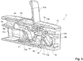
- Figure 3 shows an embodiment of the conductor connection terminal 1 as a triple connection. While the conductor connection terminal 1 of the Figure 1 has an essentially axially symmetrical mirrored structure, the component arrangement is in Figure 3 designed asymmetrically with clamping springs 4a, 4b rotated with respect to one another and clamping points or conductor entry openings 11a, 11b offset in the plane. In this way, the available installation space of the conductor connection terminal 1 is used particularly efficiently.
- two conductor connections are designed as spring-loaded terminals with clamping springs 4a, 4b for connecting electrical conductors 2a, 2b to a common busbar 3, the clamping points formed between the electrical conductors and busbar 3 being in mutually offset planes.
- the contact leg 6a of one clamping spring 4a lies opposite a clamping leg 6b of the other clamping spring 4b and vice versa.
- the components shown for the conductor connection terminal 1 differ from those shown in Figure 1 shown components as well as each other in addition in their geometric design.
- the clamping springs 4a, 4b are basically V-springs
- the clamping legs 5a, 5b and the contact legs 6a, 6b are each individually shaped.
- the contact leg 6a of the clamping spring 4a is bent slightly outwards at its free end, the clamping leg 5a of the clamping spring 4a is bent slightly inwards at its free end.
- the contact leg 6b of the clamping spring 4b merges towards the free end into a separating section 9b that is clearly bent inward, the clamping leg 5b of the clamping spring 4b is also clearly bent inwards in the transition from the clamping point to the free end. This is intended to make it clear that clamping springs 4a, 4b with different geometrical shapes can be used in the conductor connection terminal 1, so that these individual requirements for the connections to be provided are met.
- the conductor connection terminal 1 has an actuation lever 12b through which, for example, in the in Figure 3
- the clamping legs 5a of the clamping spring 4a can be displaced from an open position into a closed position and / or vice versa.
- the spring-loaded terminal connection can be opened or closed with little manual force, and the position of the Clamping leg 5a of the clamping spring 4a can be seen from the outside based on the position of the actuating lever 12b.
- the conductor connection terminal 1 shown corresponds to the structure of the in Figure 2 shown conductor connection terminal 1 partially coincide.
- a third conductor insertion opening 11c is additionally provided, which is designed as a plug connection for inserting a contact pin (not shown).
- the contact pin comes into direct contact with the busbar 3 when it is inserted, without being acted upon by additional spring force of a clamping spring.
- the contact limb 6b of the clamping spring 4b forms a stop for the contact pin, so that the contact limb 6b represents a limitation for a further conductor connection chamber 13c and thus a component of the clamping spring 4b also serves to separate the chambers.
- this further conductor connection as a printed circuit board connection or to provide other or further conductor connections on the conductor connection terminal 1.
- the clamping springs 4a, 4b are supported punctually or in sections on the common busbar 3 or are supported on this.
- the busbar 3 therefore has not only an electrical but also a mechanical function within the conductor connection terminal 1.
Landscapes
- Connections Arranged To Contact A Plurality Of Conductors (AREA)
- Multi-Conductor Connections (AREA)
- Coupling Device And Connection With Printed Circuit (AREA)
Abstract
Description
- Die Erfindung betrifft eine Leiteranschlussklemme zum Anschluss von elektrischen Leitern an eine Stromschiene. Die Leiteranschlussklemme hat ein Isolierstoffgehäuse mit mindestens zwei Leitereinführungsöffnungen und einem sich an die Leitereinführungsöffnungen anschließenden Leiteranschlussraum, eine Stromschiene und eine Klemmfeder für einen Federkraftklemmanschluss. Die Klemmfeder hat einen Klemmschenkel und einen Anlageschenkel, die durch einen Federbogen miteinander verbunden sind.
- Derartige Leiteranschlussklemmen sind bereits aus dem Stand der Technik bekannt. Gemäß der
DE 10 2014 119 421 B4 wird eine Verbindungsklemme zum Verbinden wenigstens zweier elektrischer Leiter miteinander bereitgestellt, wobei die Verbindungsklemme wenigstens zwei separate Gehäuseteile aufweist. In jedem separaten Gehäuseteil befindet sich ein Federkraftklemmanschluss zur elektrischen Kontaktierung jeweils eines elektrischen Leiters. Die Gehäuseteile werden über ein Verbindungsteil miteinander verbunden. Das Verbindungsteil kann überdies einen Leiteranschlag aufweisen, um die Einführtiefe der elektrischen Leiter zu begrenzen. - Gemäß der
WO 2017/081001 A1 soll eine kleinbauende Verbindungsklemme angegeben werden, wobei die Verbindungsklemme eine Doppelklemme mit zwei Leitereinführungsöffnungen und zwei Federkraftklemmanschlüssen ist. Hierbei wird ein verlängerter Endabschnitt des Anlageschenkels einer ersten und/oder zweiten Klemmfeder in eine Durchgangsöffnung der Stromschiene eingehängt, um eine besonders kompakte Verbindungsklemme bereitzustellen. - Vor diesem Hintergrund ist es Aufgabe der Erfindung, eine Leiteranschlussklemme mit einem kompakten Aufbau, kostengünstiger Herstellung und verbesserter Bauraumausnutzung bereitzustellen.
- Die Aufgabe wird durch eine Leiteranschlussklemme gemäß Anspruch 1 gelöst. Vorteilhafte Ausführungsformen der Leiteranschlussklemme sind den Unteransprüchen zu entnehmen.
- Es wird vorgeschlagen, dass der Klemmschenkel und/oder der Anlageschenkel der Klemmfeder einen Separierabschnitt aufweist, mittels dessen der Leiteranschlussraum in mindestens zwei räumlich voneinander getrennte Leiteranschlusskammern aufteilbar ist.
- Hierdurch wird eine Leiteranschlussklemme bereitgestellt, mit der auf besonders platzsparende und kostengünstige Weise eine Kammertrennung bereitgestellt wird, sodass die in die Leiteranschlussklemme eingeführten elektrischen Leiter einander nicht berühren und es somit nicht zu einer Anschlussbeeinträchtigung kommt. Weder starre elektrische Leiter noch Litzenleiter gelangen in eine einem anderen elektrischen Leiter zugeordnete Leiteranschlusskammer, sondern sind durch den Separierabschnitt zuverlässig räumlich von weiteren Leiteranschlusskammern getrennt, ohne dass eine Trennung durch eine gesondert hierfür vorgesehene Trennwand erforderlich ist. Es ist somit jedem elektrischen Leiter eine eigene Leiteranschlusskammer zugeordnet, indem zumindest ein Separierabschnitt durch einen Klemm- und/oder Anlageschenkel der Klemmfeder eine Kammerbegrenzung herstellt, die den gemeinsamen Anschlussraum unterteilt. Hierbei ist die Anzahl der anschließbaren elektrischen Leiter, der Leitereinführungsöffnungen und der entsprechenden Leiteranschlusskammern nicht beschränkt, sondern pro Leiteranschlussklemme variabel und kann durchaus zwei, drei oder mehr betragen. Beispielsweise können auch bei mehreren pro Leiteranschlussklemme vorgesehenen Federkraftklemmanschlüssen weitere Klemmfedern vorgesehen sein, die wahlweise ebenfalls einen Klemm- und/oder Anlageschenkel mit einem Separierabschnitt aufweisen.
- Ganz allgemein sind im Zusammenhang mit dieser Anmeldung die Wörter "ein/eine", soweit nicht ausdrücklich anders definiert, nicht als Zahlwort zu verstehen, sondern als unbestimmte Artikel mit dem Wortsinn von "mindestens ein/eine".
- Grundsätzlich wird unter dem Begriff eines "Separierabschnitts" ein einteilig mit dem Klemm- und/oder Anlageschenkel ausgebildeter Bestandteil des Schenkels verstanden. Es handelt sich um einen Bereich des Schenkels über eine vordefinierte Länge in Haupt- bzw. Längserstreckungsrichtung des Schenkels, der eine den Anschlussraum in Kammern unterteilende Wirkung entfaltet. Es ist jedoch auch denkbar, dass der Separierabschnitt durch ein zusätzliches Bauteil gebildet wird und beispielsweise als Schenkelaufsatz bedarfsweise montierbar und demontierbar ist.
- Gemäß einer vorteilhaften Ausführungsform der Erfindung weicht die Erstreckungsrichtung des Separierabschnitts von der Haupterstreckungsrichtung des den Separierabschnitt aufweisenden Klemmschenkels oder Anlageschenkels ab. Hierbei kann die Haupterstreckungsrichtung beispielsweise die Richtung sein, in die der Klemm- oder Anlageschenkel ausgehend von dem Federbogen in den Leiteranschlussraum hinein ragt. So kann der Separierabschnitt beispielsweise seitlich, nach oben oder nach unten von dem sich in Richtung des Federbogens an den Separierabschnitt anschließenden Bereich des Klemm- oder Anlageschenkels abgebogen sein. Es kann bevorzugt ein stumpfer Winkel, grundsätzlich jedoch auch ein spitzer Winkel zwischen dem Separierabschnitt und dem sich in Richtung des Federbogens an den Separierabschnitt anschließenden Bereich des Klemm- oder Anlageschenkels eingeschlossen sein. Durch den Richtungswechsel werden die unterschiedlichen Bereiche des Klemm- und/oder Anlageschenkels definiert voneinander abgegrenzt. Der Klemmschenkel hat beispielsweise zusätzlich einen Klemmabschnitt zur Ausbildung einer Klemmstelle, an der ein eingeführter elektrischer Leiter durch die Federkraft der Klemmfeder an die Stromschiene gepresst wird. Der Anlageschenkel hat beispielsweise zusätzlich einen Anlageabschnitt, über den sich die Klemmfeder an einem benachbarten oder umgebenden Bauteil abstützt. Die Klemmfeder muss sich hierbei nicht zwingend an einem umgebenden Isolierstoffgehäuse abstützen, sondern kann grundsätzlich auch selbsttragend aufgebaut sein. Der Separierabschnitt kann von dem Klemmabschnitt oder Anlageabschnitt räumlich abgegrenzt sein, insbesondere beabstandet. Die Erstreckungsrichtung des Separierabschnitts ist in Abhängigkeit der weiteren Bauteilgeometrie der Leiteranschlussklemme so gewählt, dass eine zuverlässige Kammertrennung im Sinne einer ausreichenden räumlichen Abgrenzung von mindestens zwei Leiteranschlüssen der Leiteranschlussklemme erzielt wird. Beispielsweise verläuft der Separierabschnitt im Wesentlichen senkrecht bezogen auf eine Leitereinführungsrichtung oder bezogen auf die Haupterstreckungsrichtung einer Leitereinführungsöffnung.
- Gemäß einer vorteilhaften Ausführungsform der Erfindung ist der Separierabschnitt ausgehend vom Federbogen in Richtung des freien Endes des Anlageschenkels und/oder Klemmschenkels hinter einer zwischen der Klemmfeder und einem eingeführten elektrischen Leiter ausgebildeten Klemmstelle vorgesehen. Die Kammertrennung durch den Separierabschnitt ist somit für einen von dem Federbogen abgewandten Bereich der Klemmfeder vorgesehen und räumlich von der Klemmstelle distanziert. Dadurch wird die Gefahr einer gegenseitigen Beeinträchtigung des Separierabschnitts und der Klemmstelle verringert.
- Gemäß einer vorteilhaften Ausführungsform der Erfindung schließt der Separierabschnitt mit dem freien Ende des den Separierabschnitt aufweisenden Klemmschenkels oder Anlageschenkels ab. Der Separierabschnitt bildet somit den dem Federbogen gegenüberliegenden Endbereich des Klemm- oder Anlageschenkels. Der Separierabschnitt ist somit am weitestmöglichen von der Klemmstelle entfernt ausgebildet und erhöht dadurch die Kammergröße des Leiteranschlusses, der die Klemmfeder mit dem Separierabschnitt aufweist. Zudem wird eine gegenseitige Beeinträchtigung des Separierabschnitts und der Klemmstelle verhindert.
- Gemäß einer vorteilhaften Ausführungsform der Erfindung bildet der Separierabschnitt einen Anschlag für einen in die Leiteranschlussklemme eingeführten elektrischen Leiter. Der Separierabschnitt begrenzt somit die Einführtiefe des eingeführten elektrischen Leiters und verhindert das versehentliche Einführen des elektrischen Leiters oder eines Teiles davon in eine benachbarte oder gegenüberliegende Leiteranschlusskammer.
- Gemäß einer vorteilhaften Ausführungsform der Erfindung kann der Anschlag gleichzeitig von mehreren Seiten wirksam sein, beispielsweise für zwei von gegenüberliegenden Seiten eingeführte elektrische Leiter. Der Separierabschnitt bildet somit einen Anschlag für mindestens zwei aus unterschiedlichen Richtungen in die Leiteranschlussklemme eingeführte elektrische Leiter. Hierdurch wird der für die Komponenten der Leiteranschlussklemme benötigte Bauraum deutlich reduziert. Der Anschlag verhindert eine gegenseitige Beeinträchtigung mehrerer in die Leiteranschlussklemme eingeführter Leiter.
- Gemäß einer vorteilhaften Ausführungsform der Erfindung ist mindestens ein Leiteranschluss der Leiteranschlussklemme als Steckanschluss zum Einstecken eines Kontaktstiftes ausgebildet. Weitere Leiteranschlüsse der Leiteranschlussklemme können beispielsweise als Federkraftklemmanschlüsse oder Leiterplattenanschlüsse ausgebildet sein. Der Steckanschluss zum Einstecken eines Kontaktstiftes unterscheidet sich beispielsweise von einem Federkraftklemmanschluss dadurch, dass der Steckanschluss keine Klemmfeder aufweist. Der Kontaktstift wird über den Steckanschluss in unmittelbaren Kontakt mit der Stromschiene gebracht. Optional kann der Steckanschluss beispielsweise Rastmittel zur wahlweisen Fixierung des Kontaktstiftes in der Leiteranschlussklemme aufweisen.
- Hierbei ist es vorteilhaft, wenn der Anlageschenkel der Klemmfeder einen Anschlag für den eingesteckten Kontaktstift bildet. Hierdurch wird eine weitere Kammertrennung bewirkt, indem der Anlageschenkel die Leiteranschlusskammer für den Kontaktstift begrenzt. Somit wird eine gegenseitige Beeinträchtigung des Kontaktstiftes und weiterer in die Leiteranschlussklemme eingeführter elektrischer Leiter vermieden. Weist der Anlageschenkel zusätzlich den erfindungsgemäßen Separierabschnitt auf, kommt diesem eine Mehrfachfunktion zu, da er durch den Separierabschnitt und als Anschlag für den Kontaktstift den vorhandenen Leiteranschlussraum in mindestens drei Leiteranschlusskammern unterteilt.
- Gemäß einer vorteilhaften Ausführungsform der Erfindung sind mindestens zwei Leiteranschlüsse als Federkraftklemmanschlüsse mit Klemmfedern zum Anschluss elektrischer Leiter an eine gemeinsame Stromschiene ausgebildet, wobei die zwischen den elektrischen Leitern und der Stromschiene ausgebildeten Klemmstellen in zueinander versetzten Ebenen liegen. Eine Klemmstelle ist hierbei ein Kontaktpunkt oder Kontaktbereich, in dem der angeschlossene elektrische Leiter die Stromschiene kontaktiert, wobei die Kontaktierung an der Klemmstelle durch die in Richtung der Stromschiene wirkende Federkraft des Klemmschenkels der Klemmfeder sichergestellt wird. Sind die Klemmstellen der als Federkraftklemmanschlüsse ausgebildeten Leiteranschlüsse in zueinander versetzten Ebenen angeordnet, wird das Risiko einer gegenseitigen Beeinträchtigung zweier beispielsweise in entgegengesetzten Richtungen eingeführter elektrischer Leiter weiter verringert. Zudem wird eine Bauraumausnutzung optimiert, in dem beispielsweise durch einen nicht spiegelsymmetrischen Aufbau Komponenten einer Leiteranschlusskammer teilweise in Freiräume einer anderen Leiteranschlusskammer hineinragen können, sofern dies nicht zu einer Beeinträchtigung eingeführter elektrischer Leiter führt.
- So kann gemäß einer vorteilhaften Ausführungsform der Erfindung vorgesehen sein, dass der Anlageschenkel einer ersten Klemmfeder einem Klemmschenkel einer zweiten Klemmfeder gegenüberliegt und/oder dass der Klemmschenkel der ersten Klemmfeder einem Anlageschenkel einer zweiten Klemmfeder gegenüberliegt. Die Klemmfedern werden somit nicht in achsensymmetrischer Orientierung, sondern asymmetrisch oder allenfalls in einer punkt- bzw. drehsymmetrischen Orientierung eingesetzt, sind also in ihrer Orientierung zueinander verdreht. Um bei dieser Ausführungsform den Anschluss mehrerer elektrischer Leiter an eine gemeinsame Stromschiene zu ermöglichen, kann die Stromschiene beispielsweise als doppelt gekrümmtes Bauteil, etwa annähernd mit einer S- oder Z-Form, ausgebildet sein. Hierdurch wird eine besonders bauraumoptimierte Ausführungsform zur Verfügung gestellt.
- Hierbei können sich die Klemmfedern auch punktuell oder abschnittsweise an der gemeinsamen Stromschiene abstützen oder an dieser aufgelagert sein. Somit kommt bei dieser Ausführungsform der Stromschiene nicht nur eine elektrische, sondern auch eine mechanische Funktion innerhalb der Leiteranschlussklemme zu.
- Gemäß einer vorteilhaften Ausführungsform der Erfindung können die Leiteranschlüsse und/oder die Klemmfedern der Leiteranschlussklemme asymmetrisch zueinander angeordnet sein, um die Bauraumausnutzung zu verbessern.
- Gemäß einer vorteilhaften Ausführungsform der Erfindung ist der Anlageschenkel zumindest einer Klemmfeder an der Stromschiene gelagert und hat vom Federbogen ausgehend hinter der Auflagerung des Anlageschenkels an der Stromschiene einen elastischen, auslenkbaren Federabschnitt mit einer Auflaufschräge zur Führung des anzuschließenden Leiters. Hierdurch wird eine Ausführungsform bereitgestellt, mit der der anzuschließende Leiter nicht nur mit dem Klemmschenkel, sondern zusätzlich mit einem Federabschnitt des Anlageschenkels zuverlässig kontaktiert und geklemmt wird. Durch die Auslenkbarkeit und Elastizität des Federabschnitts können elektrische Leiter unterschiedlichen Durchmessers sicher gehalten und mit ausreichender Federkraft beaufschlagt werden. Leiter mit großem Leiterquerschnitt bzw. - durchmesser werden aufgrund der Auslenkbarkeit des Federabschnitts mit genügend Federkraft seitens des Klemmschenkels und des Federabschnitts beaufschlagt, ohne dass der Leiter beispielsweise durch Quetschen, Pressen, Drücken, Klemmen oder Zwängen o.ä. eine unerwünschte Verformung erfährt. Jedoch werden auch Leiter mit kleinem Leiterquerschnitt bzw. -durchmesser aufgrund des Federabschnitts, der in diesem Fall eine geringere Auslenkung durch den eingeführten Leiter erfährt, und des Klemmschenkels besonders sicher kontaktiert und geklemmt. Mit einem Auflaufen des Leiters auf die Auflaufschräge entsteht in Abhängigkeit des Leiterquerschnitts und Leiterdurchmessers eine unterschiedliche Kontaktüberlappung.
- Gemäß einer vorteilhaften Ausführungsform der Erfindung weist die Leiteranschlussklemme einen Drücker oder Betätigungshebel auf, durch den zumindest ein Klemmschenkel einer Klemmfeder von einer Offenstellung in eine Geschlossenstellung und/oder umgekehrt verlagerbar ist. Hierdurch wird eine vereinfachte Betätigung zumindest eines Federkraftklemmanschlusses bereitgestellt. Durch die ebenfalls vorliegende Kammertrennung wird zuverlässig verhindert, dass ein anderer in die Leiteranschlussklemme eingeführter elektrischer Leiter, der nicht dem hebelkraftbetätigten Federkraftklemmanschluss zugeordnet ist, in den Schwenk- oder Betätigungsbereich des Betätigungshebels gelangt.
- Die Erfindung wird nachfolgend anhand eines Ausführungsbeispiels mit den beigefügten Zeichnungen näher erläutert. Es zeigen in schematischer Weise:
- Figur 1
- - einen Querschnitt einer als Doppelanschluss ausgeführten Leiteranschlussklemme in einer Ausführungsform mit eingesteckten elektrischen Leitern;
- Figur 2
- - einen Querschnitt einer als Doppelanschluss ausgeführten Leiteranschlussklemme in einer weiteren Ausführungsform;
- Figur 3
- - eine Perspektivansicht einer als Dreifachanschluss ausgeführten Leiteranschlussklemme.
-
Figur 1 zeigt eine Leiteranschlussklemme 1 gemäß einer vorteilhaften Ausführungsform der Erfindung. Die Leiteranschlussklemme 1 weist zwei Federkraftklemmanschlüsse auf, durch die zwei aus gegenüberliegenden Richtungen in die Leiteranschlussklemme 1 eingeführte elektrische Leiter 2a, 2b eine gemeinsame Stromschiene 3 kontaktieren. Hierzu hat die Leiteranschlussklemme 1 zwei Klemmfedern 4a, 4b mit jeweils einem Klemmschenkel 5a, 5b und jeweils einem Anlageschenkel 6a, 6b, die über einen Federbogen 7a, 7b miteinander verbunden sind. Die Klemmschenkel 5a, 5b drücken mit Federkraft den jeweils eingeführten elektrischen Leiter 2a, 2b gegen die Stromschiene 3 und stellen auf diese Weise eine sichere Kontaktierung zwischen dem Leiter 2a, 2b und der Stromschiene 3 sicher. Der Hauptkontaktpunkt zwischen dem Leiter 2a, 2b und der Stromschiene 3 wird als Klemmstelle 8a, 8b bezeichnet. - Die Klemmfeder 4a weist an ihrem Anlageschenkel 6a einen Separierabschnitt 9a auf und die Klemmfeder 4b weist an ihrem Anlageschenkel 6b einen Separierabschnitt 9b auf. Durch die Separierabschnitte 9a, 9b wird der sich an die zur Einführung der elektrischen Leiter 2a, 2b vorgesehenen Leitereinführungsöffnungen 11a, 11b anschließende Anschlussraum in mehrere räumlich voneinander getrennte Leiteranschlusskammern (vgl.
Figuren 2 und3 ) unterteilt und somit eine Kammertrennung bereitgestellt. Mithilfe der Separierabschnitte 9a, 9b wird gewährleistet, dass die elektrischen Leiter 2a, 2b nicht in den gegenüberliegenden Anschlussbereich gelangen und sich nicht gegenseitig beeinträchtigen. Der Separierabschnitt 9a, 9b ist ausgehend vom Federbogen 7a, 7b in Richtung des freien Endes des Anlageschenkels 6a, 6b hinter der Klemmstelle 8a, 8b vorgesehen. - Die Separierabschnitte 9a, 9b sind vorliegend jeweils als Anschlag für den elektrischen Leiter 2a, 2b ausgebildet und schließen mit dem freien Ende des jeweiligen Anlageschenkels 6a, 6b ab. Die Separierabschnitte 9a, 9b sind in einem vordefinierten Abstand von dem Federbogen 7a, 7b von dem Anlageschenkel 6a, 6b abgebogen, sodass die Erstreckungsrichtung des Separierabschnitts 9a, 9b von der Haupterstreckungsrichtung des den Separierabschnitt 9a, 9b aufweisenden Anlageschenkels 6a, 6b abweicht, und erstrecken sich im Wesentlichen senkrecht zur Leitereinführungsrichtung. Es ist jedoch grundsätzlich auch denkbar, den Klemmschenkel 5a, 5b zu verlängern und an diesem einen Separierabschnitt vorzusehen. Zudem muss der Separierabschnitt 9a, 9b nicht am Ende des Anlageschenkels angeordnet sein, sondern es können sich weitere Abschnitte, beispielsweise ein nochmals abgebogener Bereich zur Führung des elektrischen Leiters 2a, 2b anschließen. Des Weiteren muss der Separierabschnitt 9a, 9b nicht wie in den Figuren gezeigt nach oben abgebogen sein, sondern kann auch als seitlich von dem Anlage- oder Klemmschenkel abragender Vorsprung eine Kammerbegrenzung ausbilden.
- Die Leiteranschlussklemme 1 hat ein Isolierstoffgehäuse 10, das die Bauteile der Leiteranschlussklemme 1 vor äußeren physikalischen und chemischen Einwirkungen schützt und aus einem elektrisch isolierenden Material wie beispielsweise Kunststoff besteht. Das Isolierstoffgehäuse 22 umgibt die Leiteranschlussklemme 1 nahezu vollständig, enthält jedoch zumindest Leitereinführungsöffnungen 11a, 11 b zum Einführen elektrischer Leiter 2a, 2b in die Leiteranschlussklemme 1.
- Zur Betätigung der Federkraftklemmanschlüsse weist die in
Figur 1 gezeigte Leiteranschlussklemme 1 Drücker 12a auf. Mithilfe der Drücker 12a können die Klemmschenkel 5a, 5b manuell in Richtung der Anlageschenkel 6a, 6b verlagert werden, um den Leiter 2a, 2b wie insbesondere auch mehrdrähtige Leiter 2a, 2b leichter einführen oder wieder lösen und zwischen dem Klemmschenkel 5a, 5b und der Stromschiene 3 positionieren zu können. - Der Anlageschenkel 6a, 6b ist an der Stromschiene 3 an einer Auflagerung 15 gelagert, sodass sich der Anlageschenkel 6a, 6b gegen die Stromschiene 3 abstützt. Hierzu hat die Stromschiene 3 auf jeder Anschlussseite eine Ausnehmung, durch die der Anlageschenkel 6a, 6b geführt ist. Ausgehend von der Auflagerung 15 in Richtung des Separierabschnitts 9a, 9b des Anlageschenkels 6a, 6b erstreckt sich ein elastischer, auslenkbarer Federabschnitt 14 mit einer Auflaufschräge zur Führung des Leiters 2a, 2b. Aufgrund der Elastizität des Federabschnitts 14 wird dieser beim Einführen eines Leiters 2a, 2b in Abhängigkeit des Leiterdurchmessers verlagert und passt sich somit unterschiedlichen Leiterquerschnitten an.
-
Figur 2 zeigt eine als Doppelanschluss ausgeführte Leiteranschlussklemme 1 gemäß einer weiteren Ausführungsform. Auf einer Seite der Leiteranschlussklemme 1 ist eine Klemmfeder 4b eingesetzt. Eine weitere, nicht gezeigte Klemmfeder ist auf der gegenüberliegenden Seite der Leiteranschlussklemme 1 einsetzbar. InFigur 2 sind zwei Leiteranschlüsse als Federkraftklemmanschlüsse mit Klemmfedern 4b zum Anschluss elektrischer Leiter 2a, 2b an eine gemeinsame Stromschiene 3 ausgebildet, wobei die zwischen den elektrischen Leitern und der Stromschiene 3 ausgebildeten Klemmstellen in zueinander versetzten Ebenen liegen. Der Anlageschenkel 6b der Klemmfeder 4b geht zum freien Ende hin in einen deutlich nach innen abgebogenen Separierabschnitt 9b über, der Klemmschenkel 5b der Klemmfeder 4b ist im Übergang von der Klemmstelle zum freien Ende hin ebenfalls deutlich nach innen gebogen. Zur Betätigung zumindest eines Federkraftklemmanschlusses der Leiteranschlussklemme 1 weist die Leiteranschlussklemme 1 einen Betätigungshebel 12b auf. - Die Klemmfeder 4b weist einen Separierabschnitt 9b auf, um eine Kammertrennung zu ermöglichen. Wie in
Figur 2 ersichtlich begrenzt der Separierabschnitt 9b eine Leiteranschlusskammer 13b und würde bereits ausreichen, um auf der von der Leiteranschlusskammer 13b abgewandten Seite eine zusätzliche Leiteranschlusskammer für einen in die Leitereinführungsöffnung 11a eingesteckten elektrischen Leiter 2a zu definieren. Hierbei wäre es auch denkbar, dass der Separierabschnitt 9b einen Anschlag für mindestens zwei aus unterschiedlichen Richtungen in die Leiteranschlussklemme 1 eingeführte elektrische Leiter 2a, 2b bildet. In der inFigur 2 gezeigten Ausführungsform wird zusätzlich durch die geometrische Form der Stromschiene 3 eine Kammertrennung herbeigeführt, indem die Stromschiene 3 im Wesentlichen aus zwei horizontalen Hauptabschnitten und einem vertikalen Hauptabschnitt besteht, die spiegelverkehrt z-förmig angeordnet sind. Der vertikale Hauptabschnitt der Stromschiene 3, der die zwei horizontalen Hauptabschnitte der Stromschiene 3 verbindet, bildet eine Kammerbegrenzung für die Leiteranschlusskammer 13a. Überdies kann ein vertikaler Nebenabschnitt der Stromschiene 3 vorgesehen sein, der sich beispielsweise in Richtung des Anlageschenkels 6b der Klemmfeder 6b erstreckt und mittels einer Durchbrechung in dem vertikalen Nebenabschnitt eine Auflagerung 15 für den Anlageschenkel 6b bildet. -
Figur 3 zeigt eine Ausführungsform der Leiteranschlussklemme 1 als Dreifachanschluss. Während die Leiteranschlussklemme 1 derFigur 1 einen im Wesentlichen achsensymmetrisch gespiegelten Aufbau besitzt, ist die Bauteilanordnung inFigur 3 mit zueinander rotierten Klemmfedern 4a, 4b und in der Ebene versetzten Klemmstellen bzw. Leitereinführungsöffnungen 11a, 11b asymmetrisch gestaltet. Auf diese Weise wird der verfügbare Bauraum der Leiteranschlussklemme 1 besonders effizient ausgenutzt. InFigur 3 sind zwei Leiteranschlüsse als Federkraftklemmanschlüsse mit Klemmfedern 4a, 4b zum Anschluss elektrischer Leiter 2a, 2b an eine gemeinsame Stromschiene 3 ausgebildet, wobei die zwischen den elektrischen Leitern und der Stromschiene 3 ausgebildeten Klemmstellen in zueinander versetzten Ebenen liegen. Der Anlageschenkel 6a der einen Klemmfeder 4a liegt einem Klemmschenkel 6b der anderen Klemmfeder 4b gegenüber und umgekehrt. Die inFigur 3 gezeigten Komponenten der Leiteranschlussklemme 1 unterscheiden sich von den inFigur 1 gezeigten Bauteilen sowie untereinander zusätzlich in ihrer geometrischen Ausgestaltung. So handelt es sich bei den Klemmfedern 4a, 4b zwar prinzipiell um V-Federn, die Klemmschenkel 5a, 5b und die Anlageschenkel 6a, 6b sind jedoch jeweils individuell geformt. Der Anlageschenkel 6a der Klemmfeder 4a ist an seinem freien Ende leicht nach außen gebogen, der Klemmschenkel 5a der Klemmfeder 4a ist an seinem freien Ende leicht nach innen gebogen. Der Anlageschenkel 6b der Klemmfeder 4b geht zum freien Ende hin in einen deutlich nach innen abgebogenen Separierabschnitt 9b über, der Klemmschenkel 5b der Klemmfeder 4b ist im Übergang von der Klemmstelle zum freien Ende hin ebenfalls deutlich nach innen gebogen. Hierdurch soll verdeutlicht werden, dass geometrisch unterschiedlich geformte Klemmfedern 4a, 4b in der Leiteranschlussklemme 1 zum Einsatz kommen können, sodass diese individuellen Anforderungen an die bereitzustellenden Anschlüsse gerecht wird. - Zur Betätigung zumindest eines Federkraftklemmanschlusses der Leiteranschlussklemme 1 weist die Leiteranschlussklemme 1 einen Betätigungshebel 12b auf, durch den beispielsweise in der in
Figur 3 gezeigten Ausführungsform der Klemmschenkel 5a der Klemmfeder 4a von einer Offenstellung in eine Geschlossenstellung und/oder umgekehrt verlagerbar ist. Hierdurch kann der Federkraftklemmanschluss mit geringer manueller Kraft geöffnet oder geschlossen werden, zudem ist die Stellung des Klemmschenkels 5a der Klemmfeder 4a anhand der Stellung des Betätigungshebels 12b von außen erkennbar. - Der grundsätzliche Aufbau der in
Figur 3 gezeigten Leiteranschlussklemme 1 stimmt mit dem Aufbau der inFigur 2 gezeigten Leiteranschlussklemme 1 teilweise überein. Es ist jedoch ergänzend eine dritte Leitereinführungsöffnung 11c vorgesehen, die als Steckanschluss zum Einstecken eines nicht gezeigten Kontaktstiftes ausgebildet ist. Hierbei gelangt der Kontaktstift beim Einstecken in direkten Kontakt mit der Stromschiene 3, ohne durch zusätzliche Federkraft einer Klemmfeder beaufschlagt zu sein. Zugleich bildet der Anlageschenkel 6b der Klemmfeder 4b einen Anschlag für den Kontaktstift, sodass der Anlageschenkel 6b eine Begrenzung für eine weitere Leiteranschlusskammer 13c darstellt und somit auch hier ein Bestandteil der Klemmfeder 4b der Kammertrennung dient. Grundsätzlich ist es auch denkbar, diesen weiteren Leiteranschluss als Leiterplattenanschluss auszubilden oder andere bzw. weitere Leiteranschlüsse an der Leiteranschlussklemme 1 vorzusehen. - In den
Figuren 1 bis 3 ist gezeigt, dass sich die Klemmfedern 4a, 4b punktuell oder abschnittsweise an der gemeinsamen Stromschiene 3 abstützen oder an dieser aufgelagert sind. Somit kommt bei dieser Ausführungsform der Stromschiene 3 nicht nur eine elektrische, sondern auch eine mechanische Funktion innerhalb der Leiteranschlussklemme 1 zu. -
- 1
- Leiteranschlussklemme
- 2a
- Leiter
- 2b
- Leiter
- 3
- Stromschiene
- 4a
- Klemmfeder
- 4b
- Klemmfeder
- 5a
- Klemmschenkel
- 5b
- Klemmschenkel
- 6a
- Anlageschenkel
- 6b
- Anlageschenkel
- 7a
- Federbogen
- 7b
- Federbogen
- 8a
- Klemmstelle
- 8b
- Klemmstelle
- 9a
- Separierabschnitt
- 9b
- Separierabschnitt
- 10
- Isolierstoffgehäuse
- 11a
- Leitereinführungsöffnung
- 11b
- Leitereinführungsöffnung
- 11c
- Leitereinführungsöffnung
- 12a
- Drücker
- 12b
- Betätigungshebel
- 13a
- Leiteranschlusskammer
- 13b
- Leiteranschlusskammer
- 13c
- Leiteranschlusskammer
- 14
- Federabschnitt
- 15
- Auflagerung
Claims (14)
- Leiteranschlussklemme (1) zum Anschluss von elektrischen Leitern (2a, 2b) an eine Stromschiene (3), wobei die Leiteranschlussklemme (1) ein Isolierstoffgehäuse (10) mit mindestens zwei Leitereinführungsöffnungen (11a, 11b, 11c) und einem sich an die Leitereinführungsöffnungen (11a, 11b, 11c) anschließenden Leiteranschlussraum, eine Stromschiene (3) und eine Klemmfeder (4a, 4b) für einen Federkraftklemmanschluss hat, und wobei die Klemmfeder (4a, 4b) einen Klemmschenkel (5a, 5b) und einen Anlageschenkel (6a, 6b) hat, die durch einen Federbogen (7a, 7b) miteinander verbunden sind, dadurch gekennzeichnet, dass der Klemmschenkel (5a, 5b) und/oder der Anlageschenkel (6a, 6b) der Klemmfeder (4a, 4b) einen Separierabschnitt (9a, 9b) aufweist, mittels dessen der Leiteranschlussraum in mindestens zwei räumlich voneinander getrennte Leiteranschlusskammern (13a, 13b, 13c) aufteilbar ist.
- Leiteranschlussklemme (1) nach Anspruch 1, dadurch gekennzeichnet, dass die Erstreckungsrichtung des Separierabschnitts (9a, 9b) von der Haupterstreckungsrichtung des den Separierabschnitt (9a, 9b) aufweisenden Klemmschenkels (5a, 5b) oder Anlageschenkels (6a, 6b) abweicht.
- Leiteranschlussklemme (1) nach Anspruch 1 oder 2, dadurch gekennzeichnet, dass der Separierabschnitt (9a, 9b) ausgehend vom Federbogen (7a, 7b) in Richtung des freien Endes des Anlageschenkels (6a, 6b) und/oder Klemmschenkels (5a, 5b) hinter einer zwischen der Klemmfeder (4a, 4b) und einem eingeführten elektrischen Leiter (2a, 2b) ausgebildeten Klemmstelle (8a, 8b) vorgesehen ist.
- Leiteranschlussklemme (1) nach einem der vorhergehenden Ansprüche,
dadurch gekennzeichnet, dass der Separierabschnitt (9a, 9b) mit dem freien Ende des den Separierabschnitt (9a, 9b) aufweisenden Klemmschenkels (5a, 5b) oder Anlageschenkels (6a, 6b) abschließt. - Leiteranschlussklemme (1) nach einem der vorhergehenden Ansprüche,
dadurch gekennzeichnet, dass der Separierabschnitt (9a, 9b) einen Anschlag für einen in die Leiteranschlussklemme (1) eingeführten elektrischen Leiter (2a, 2b) bildet. - Leiteranschlussklemme (1) nach einem der vorhergehenden Ansprüche,
dadurch gekennzeichnet, dass der Separierabschnitt (9a, 9b) einen Anschlag für mindestens zwei aus unterschiedlichen Richtungen in die Leiteranschlussklemme (1) eingeführte elektrische Leiter (2a, 2b) bildet. - Leiteranschlussklemme (1) nach einem der vorhergehenden Ansprüche,
dadurch gekennzeichnet, dass mindestens ein Leiteranschluss als Steckanschluss zum Einstecken eines Kontaktstiftes ausgebildet ist. - Leiteranschlussklemme (1) nach Anspruch 7, dadurch gekennzeichnet, dass der Anlageschenkel (6a, 6b) der Klemmfeder (4a, 4b) einen Anschlag für den eingesteckten Kontaktstift bildet.
- Leiteranschlussklemme (1) nach einem der vorhergehenden Ansprüche,
dadurch gekennzeichnet, dass mindestens zwei Leiteranschlüsse als Federkraftklemmanschlüsse mit Klemmfedern (4a, 4b) zum Anschluss elektrischer Leiter (2a, 2b) an eine gemeinsame Stromschiene (3) ausgebildet sind, wobei die zwischen den elektrischen Leitern (2a, 2b) und der Stromschiene (3) ausgebildeten Klemmstellen (8a, 8b) in zueinander versetzten Ebenen liegen. - Leiteranschlussklemme (1) nach Anspruch 9, dadurch gekennzeichnet, dass der Anlageschenkel (6a, 6b) einer ersten Klemmfeder (4a, 4b) einem Klemmschenkel (5a, 5b) einer zweiten Klemmfeder (4a, 4b) gegenüberliegt.
- Leiteranschlussklemme (1) nach Anspruch 9 oder 10, dadurch gekennzeichnet, dass sich die Klemmfedern (4a, 4b) punktuell oder abschnittsweise an der gemeinsamen Stromschiene (3) abstützen oder an dieser aufgelagert sind.
- Leiteranschlussklemme (1) nach einem der Ansprüche 9 bis 11, dadurch gekennzeichnet, dass die Leiteranschlüsse und/oder die Klemmfedern (4a, 4b) asymmetrisch oder rotationssymmetrisch zueinander angeordnet sind.
- Leiteranschlussklemme (1) nach einem der vorhergehenden Ansprüche, dadurch gekennzeichnet, dass der Anlageschenkel (6a, 6b) zumindest einer Klemmfeder (4a, 4b) an der Stromschiene (3) gelagert ist und vom Federbogen (7a, 7b) ausgehend hinter der Auflagerung (15) des Anlageschenkels (6a, 6b) an der Stromschiene (3) einen elastischen, auslenkbaren Federabschnitt (14) mit einer Auflaufschräge zur Führung des anzuschließenden Leiters (2a, 2b) hat.
- Leiteranschlussklemme (1) nach einem der vorhergehenden Ansprüche, dadurch gekennzeichnet, dass die Leiteranschlussklemme (1) einen Drücker (12a) oder Betätigungshebel (12b) aufweist, durch den zumindest ein Klemmschenkel (5a, 5b) einer Klemmfeder (4a, 4b) von einer Offenstellung in eine Geschlossenstellung und/oder umgekehrt verlagerbar ist.
Applications Claiming Priority (1)
| Application Number | Priority Date | Filing Date | Title |
|---|---|---|---|
| DE202020100089.6U DE202020100089U1 (de) | 2020-01-09 | 2020-01-09 | Leiteranschlussklemme |
Publications (2)
| Publication Number | Publication Date |
|---|---|
| EP3849018A1 true EP3849018A1 (de) | 2021-07-14 |
| EP3849018B1 EP3849018B1 (de) | 2024-09-11 |
Family
ID=73793054
Family Applications (1)
| Application Number | Title | Priority Date | Filing Date |
|---|---|---|---|
| EP20213062.1A Active EP3849018B1 (de) | 2020-01-09 | 2020-12-10 | Leiteranschlussklemme |
Country Status (2)
| Country | Link |
|---|---|
| EP (1) | EP3849018B1 (de) |
| DE (1) | DE202020100089U1 (de) |
Cited By (2)
| Publication number | Priority date | Publication date | Assignee | Title |
|---|---|---|---|---|
| CN114384447A (zh) * | 2021-12-02 | 2022-04-22 | 华能国际电力股份有限公司德州电厂 | 一种用于仪表伴热远程监测与报警的装置 |
| WO2023227389A1 (de) * | 2022-05-23 | 2023-11-30 | Electro Terminal Gmbh & Co Kg | Klemme mit lösehebel und drücker |
Families Citing this family (1)
| Publication number | Priority date | Publication date | Assignee | Title |
|---|---|---|---|---|
| LU102793B1 (de) * | 2021-04-29 | 2022-10-31 | Phoenix Contact Gmbh & Co | Klemmfeder, Anschlussanordnung und Anschlussklemme |
Citations (9)
| Publication number | Priority date | Publication date | Assignee | Title |
|---|---|---|---|---|
| JPH09147931A (ja) * | 1995-11-17 | 1997-06-06 | Tec Corp | 電線接続装置 |
| DE29920231U1 (de) * | 1999-11-17 | 2001-04-05 | Weidmüller Interface GmbH & Co, 32760 Detmold | Schraubenlose Anschlußklemme |
| DE102010010260A1 (de) * | 2010-03-03 | 2011-09-08 | Wago Verwaltungsgesellschaft Mbh | Steckverbinder |
| EP2605335A2 (de) * | 2011-12-14 | 2013-06-19 | Wago Verwaltungsgesellschaft mbH | Anschlussklemme |
| EP2947718A1 (de) * | 2014-05-23 | 2015-11-25 | Berker GmbH & Co. KG | Federbelastete Anschlussklemme |
| DE102014119421B4 (de) | 2014-12-22 | 2017-02-02 | Wago Verwaltungsgesellschaft Mbh | Verbindungsklemme und Verfahren zur Montage einer Verbindungsklemme |
| WO2017081001A1 (de) | 2015-11-09 | 2017-05-18 | Wago Verwaltungsgesellschaft Mbh | Verbindungsklemme |
| DE202017105467U1 (de) * | 2017-09-08 | 2018-12-12 | Wago Verwaltungsgesellschaft Mbh | Leiteranschlussklemme |
| CN109309295A (zh) * | 2017-07-28 | 2019-02-05 | 沃自头瑞有限公司 | 用于连接电源电线的连接器 |
Family Cites Families (6)
| Publication number | Priority date | Publication date | Assignee | Title |
|---|---|---|---|---|
| US2713668A (en) * | 1951-06-21 | 1955-07-19 | Hart Mfg Co | Quick detachable electrical connector |
| DE7617711U1 (de) * | 1976-06-03 | 1976-11-04 | Adels Verwaltungs-Gesellschaft Mbh, 5070 Bergisch Gladbach | Elektrisch leitender Kontakteinsatz für Verbindungsklemmen |
| DE3044133C2 (de) * | 1980-11-24 | 1982-12-16 | Siemens AG, 1000 Berlin und 8000 München | Schraubenlose Klemme |
| DE3237947A1 (de) * | 1982-10-13 | 1984-04-19 | Rafi Gmbh & Co Elektrotechnische Spezialfabrik, 7981 Berg | Vorrichtung zur schraubenlosen verbindung zweier teile |
| DE102013101830B4 (de) * | 2013-01-08 | 2017-12-28 | Wago Verwaltungsgesellschaft Mbh | Elektrische Anschlussklemme und Verfahren zu dessen Montage |
| DE102018117508B4 (de) * | 2018-07-19 | 2024-01-18 | Wago Verwaltungsgesellschaft Mbh | Leiteranschlussklemme |
-
2020
- 2020-01-09 DE DE202020100089.6U patent/DE202020100089U1/de active Active
- 2020-12-10 EP EP20213062.1A patent/EP3849018B1/de active Active
Patent Citations (9)
| Publication number | Priority date | Publication date | Assignee | Title |
|---|---|---|---|---|
| JPH09147931A (ja) * | 1995-11-17 | 1997-06-06 | Tec Corp | 電線接続装置 |
| DE29920231U1 (de) * | 1999-11-17 | 2001-04-05 | Weidmüller Interface GmbH & Co, 32760 Detmold | Schraubenlose Anschlußklemme |
| DE102010010260A1 (de) * | 2010-03-03 | 2011-09-08 | Wago Verwaltungsgesellschaft Mbh | Steckverbinder |
| EP2605335A2 (de) * | 2011-12-14 | 2013-06-19 | Wago Verwaltungsgesellschaft mbH | Anschlussklemme |
| EP2947718A1 (de) * | 2014-05-23 | 2015-11-25 | Berker GmbH & Co. KG | Federbelastete Anschlussklemme |
| DE102014119421B4 (de) | 2014-12-22 | 2017-02-02 | Wago Verwaltungsgesellschaft Mbh | Verbindungsklemme und Verfahren zur Montage einer Verbindungsklemme |
| WO2017081001A1 (de) | 2015-11-09 | 2017-05-18 | Wago Verwaltungsgesellschaft Mbh | Verbindungsklemme |
| CN109309295A (zh) * | 2017-07-28 | 2019-02-05 | 沃自头瑞有限公司 | 用于连接电源电线的连接器 |
| DE202017105467U1 (de) * | 2017-09-08 | 2018-12-12 | Wago Verwaltungsgesellschaft Mbh | Leiteranschlussklemme |
Cited By (3)
| Publication number | Priority date | Publication date | Assignee | Title |
|---|---|---|---|---|
| CN114384447A (zh) * | 2021-12-02 | 2022-04-22 | 华能国际电力股份有限公司德州电厂 | 一种用于仪表伴热远程监测与报警的装置 |
| CN114384447B (zh) * | 2021-12-02 | 2026-04-10 | 华能国际电力股份有限公司德州电厂 | 一种用于仪表伴热远程监测与报警的装置 |
| WO2023227389A1 (de) * | 2022-05-23 | 2023-11-30 | Electro Terminal Gmbh & Co Kg | Klemme mit lösehebel und drücker |
Also Published As
| Publication number | Publication date |
|---|---|
| DE202020100089U1 (de) | 2021-04-12 |
| EP3849018B1 (de) | 2024-09-11 |
Similar Documents
| Publication | Publication Date | Title |
|---|---|---|
| EP3324490B1 (de) | Federklemmkontakt zur kontaktierung elektrischer leiter, leiteranschlussklemme und verfahren zur herstellung eines federklemmkontakts | |
| EP3298659B1 (de) | Leiteranschlussklemme | |
| EP2956993B1 (de) | Federklemmkontakt und verbindungsklemme für elektrische leiter | |
| EP4224635B1 (de) | Leiteranschlussklemme | |
| DE102013111574B4 (de) | Federkraftklemmanschluss und Steckverbinder | |
| EP3125372B2 (de) | Anschlussklemme | |
| EP3375046B1 (de) | Elektrische anschlussklemme | |
| DE102019132316A1 (de) | Federkraftklemme für Leiter | |
| EP3111513A1 (de) | Verbindungsklemme und federkraftklemmkontakt hierzu | |
| EP3849018B1 (de) | Leiteranschlussklemme | |
| WO2012083320A1 (de) | Anschluss- oder verbindungsklemme für elektrische leiter | |
| EP3477793A2 (de) | Abgriffsteckverbinder | |
| DE102015119407A1 (de) | Anschlussklemme und Mehrfachklemme | |
| DE102015119484A1 (de) | Steckkontakt | |
| EP3849019B1 (de) | Leiteranschlussklemme | |
| DE102020128775B4 (de) | Leiteranschlussklemme in Form eines Verteilerklemmenblocks | |
| DE202007009193U1 (de) | Elektrischer Steckverbinder mit Schenkelfederklemme | |
| EP4320688B1 (de) | Verbindungsklemme zum verbinden wenigstens zweier elektrischer leiter | |
| EP3038213B1 (de) | Leiteranschlussklemme zum anklemmen wenigstens eines elektrischen leiters | |
| EP1523065B1 (de) | Elektrische Klemme | |
| DE102019120306B4 (de) | Leiteranschlussklemme zum Anschluss wenigstens eines elektrischen Leiters | |
| DE29900402U1 (de) | Elektrische Anschlußklemme | |
| DE2706988A1 (de) | Schraubenlose anschlussklemme zur stromuebertragung von elektrischen leitern | |
| EP3667826B1 (de) | Leiteranschlussklemme | |
| DE202014011415U1 (de) | Anschlussklemme |
Legal Events
| Date | Code | Title | Description |
|---|---|---|---|
| PUAI | Public reference made under article 153(3) epc to a published international application that has entered the european phase |
Free format text: ORIGINAL CODE: 0009012 |
|
| STAA | Information on the status of an ep patent application or granted ep patent |
Free format text: STATUS: THE APPLICATION HAS BEEN PUBLISHED |
|
| AK | Designated contracting states |
Kind code of ref document: A1 Designated state(s): AL AT BE BG CH CY CZ DE DK EE ES FI FR GB GR HR HU IE IS IT LI LT LU LV MC MK MT NL NO PL PT RO RS SE SI SK SM TR |
|
| STAA | Information on the status of an ep patent application or granted ep patent |
Free format text: STATUS: REQUEST FOR EXAMINATION WAS MADE |
|
| 17P | Request for examination filed |
Effective date: 20210806 |
|
| RBV | Designated contracting states (corrected) |
Designated state(s): AL AT BE BG CH CY CZ DE DK EE ES FI FR GB GR HR HU IE IS IT LI LT LU LV MC MK MT NL NO PL PT RO RS SE SI SK SM TR |
|
| STAA | Information on the status of an ep patent application or granted ep patent |
Free format text: STATUS: EXAMINATION IS IN PROGRESS |
|
| 17Q | First examination report despatched |
Effective date: 20221026 |
|
| GRAP | Despatch of communication of intention to grant a patent |
Free format text: ORIGINAL CODE: EPIDOSNIGR1 |
|
| STAA | Information on the status of an ep patent application or granted ep patent |
Free format text: STATUS: GRANT OF PATENT IS INTENDED |
|
| RIC1 | Information provided on ipc code assigned before grant |
Ipc: H01R 11/05 20060101ALN20240508BHEP Ipc: H01R 9/24 20060101ALI20240508BHEP Ipc: H01R 4/48 20060101AFI20240508BHEP |
|
| INTG | Intention to grant announced |
Effective date: 20240527 |
|
| GRAS | Grant fee paid |
Free format text: ORIGINAL CODE: EPIDOSNIGR3 |
|
| GRAA | (expected) grant |
Free format text: ORIGINAL CODE: 0009210 |
|
| STAA | Information on the status of an ep patent application or granted ep patent |
Free format text: STATUS: THE PATENT HAS BEEN GRANTED |
|
| AK | Designated contracting states |
Kind code of ref document: B1 Designated state(s): AL AT BE BG CH CY CZ DE DK EE ES FI FR GB GR HR HU IE IS IT LI LT LU LV MC MK MT NL NO PL PT RO RS SE SI SK SM TR |
|
| REG | Reference to a national code |
Ref country code: GB Ref legal event code: FG4D Free format text: NOT ENGLISH |
|
| REG | Reference to a national code |
Ref country code: CH Ref legal event code: EP |
|
| REG | Reference to a national code |
Ref country code: DE Ref legal event code: R096 Ref document number: 502020009182 Country of ref document: DE |
|
| REG | Reference to a national code |
Ref country code: IE Ref legal event code: FG4D Free format text: LANGUAGE OF EP DOCUMENT: GERMAN |
|
| REG | Reference to a national code |
Ref country code: LT Ref legal event code: MG9D |
|
| PG25 | Lapsed in a contracting state [announced via postgrant information from national office to epo] |
Ref country code: NO Free format text: LAPSE BECAUSE OF FAILURE TO SUBMIT A TRANSLATION OF THE DESCRIPTION OR TO PAY THE FEE WITHIN THE PRESCRIBED TIME-LIMIT Effective date: 20241211 |
|
| REG | Reference to a national code |
Ref country code: NL Ref legal event code: MP Effective date: 20240911 |
|
| PG25 | Lapsed in a contracting state [announced via postgrant information from national office to epo] |
Ref country code: FI Free format text: LAPSE BECAUSE OF FAILURE TO SUBMIT A TRANSLATION OF THE DESCRIPTION OR TO PAY THE FEE WITHIN THE PRESCRIBED TIME-LIMIT Effective date: 20240911 Ref country code: GR Free format text: LAPSE BECAUSE OF FAILURE TO SUBMIT A TRANSLATION OF THE DESCRIPTION OR TO PAY THE FEE WITHIN THE PRESCRIBED TIME-LIMIT Effective date: 20241212 |
|
| PG25 | Lapsed in a contracting state [announced via postgrant information from national office to epo] |
Ref country code: BG Free format text: LAPSE BECAUSE OF FAILURE TO SUBMIT A TRANSLATION OF THE DESCRIPTION OR TO PAY THE FEE WITHIN THE PRESCRIBED TIME-LIMIT Effective date: 20240911 |
|
| PG25 | Lapsed in a contracting state [announced via postgrant information from national office to epo] |
Ref country code: LV Free format text: LAPSE BECAUSE OF FAILURE TO SUBMIT A TRANSLATION OF THE DESCRIPTION OR TO PAY THE FEE WITHIN THE PRESCRIBED TIME-LIMIT Effective date: 20240911 |
|
| PG25 | Lapsed in a contracting state [announced via postgrant information from national office to epo] |
Ref country code: HR Free format text: LAPSE BECAUSE OF FAILURE TO SUBMIT A TRANSLATION OF THE DESCRIPTION OR TO PAY THE FEE WITHIN THE PRESCRIBED TIME-LIMIT Effective date: 20240911 |
|
| PG25 | Lapsed in a contracting state [announced via postgrant information from national office to epo] |
Ref country code: ES Free format text: LAPSE BECAUSE OF FAILURE TO SUBMIT A TRANSLATION OF THE DESCRIPTION OR TO PAY THE FEE WITHIN THE PRESCRIBED TIME-LIMIT Effective date: 20240911 Ref country code: RS Free format text: LAPSE BECAUSE OF FAILURE TO SUBMIT A TRANSLATION OF THE DESCRIPTION OR TO PAY THE FEE WITHIN THE PRESCRIBED TIME-LIMIT Effective date: 20241211 |
|
| PG25 | Lapsed in a contracting state [announced via postgrant information from national office to epo] |
Ref country code: RS Free format text: LAPSE BECAUSE OF FAILURE TO SUBMIT A TRANSLATION OF THE DESCRIPTION OR TO PAY THE FEE WITHIN THE PRESCRIBED TIME-LIMIT Effective date: 20241211 Ref country code: NO Free format text: LAPSE BECAUSE OF FAILURE TO SUBMIT A TRANSLATION OF THE DESCRIPTION OR TO PAY THE FEE WITHIN THE PRESCRIBED TIME-LIMIT Effective date: 20241211 Ref country code: LV Free format text: LAPSE BECAUSE OF FAILURE TO SUBMIT A TRANSLATION OF THE DESCRIPTION OR TO PAY THE FEE WITHIN THE PRESCRIBED TIME-LIMIT Effective date: 20240911 Ref country code: HR Free format text: LAPSE BECAUSE OF FAILURE TO SUBMIT A TRANSLATION OF THE DESCRIPTION OR TO PAY THE FEE WITHIN THE PRESCRIBED TIME-LIMIT Effective date: 20240911 Ref country code: GR Free format text: LAPSE BECAUSE OF FAILURE TO SUBMIT A TRANSLATION OF THE DESCRIPTION OR TO PAY THE FEE WITHIN THE PRESCRIBED TIME-LIMIT Effective date: 20241212 Ref country code: FI Free format text: LAPSE BECAUSE OF FAILURE TO SUBMIT A TRANSLATION OF THE DESCRIPTION OR TO PAY THE FEE WITHIN THE PRESCRIBED TIME-LIMIT Effective date: 20240911 Ref country code: ES Free format text: LAPSE BECAUSE OF FAILURE TO SUBMIT A TRANSLATION OF THE DESCRIPTION OR TO PAY THE FEE WITHIN THE PRESCRIBED TIME-LIMIT Effective date: 20240911 Ref country code: BG Free format text: LAPSE BECAUSE OF FAILURE TO SUBMIT A TRANSLATION OF THE DESCRIPTION OR TO PAY THE FEE WITHIN THE PRESCRIBED TIME-LIMIT Effective date: 20240911 |
|
| PG25 | Lapsed in a contracting state [announced via postgrant information from national office to epo] |
Ref country code: NL Free format text: LAPSE BECAUSE OF FAILURE TO SUBMIT A TRANSLATION OF THE DESCRIPTION OR TO PAY THE FEE WITHIN THE PRESCRIBED TIME-LIMIT Effective date: 20240911 |
|
| PG25 | Lapsed in a contracting state [announced via postgrant information from national office to epo] |
Ref country code: PT Free format text: LAPSE BECAUSE OF FAILURE TO SUBMIT A TRANSLATION OF THE DESCRIPTION OR TO PAY THE FEE WITHIN THE PRESCRIBED TIME-LIMIT Effective date: 20250113 Ref country code: IS Free format text: LAPSE BECAUSE OF FAILURE TO SUBMIT A TRANSLATION OF THE DESCRIPTION OR TO PAY THE FEE WITHIN THE PRESCRIBED TIME-LIMIT Effective date: 20250111 |
|
| PG25 | Lapsed in a contracting state [announced via postgrant information from national office to epo] |
Ref country code: RO Free format text: LAPSE BECAUSE OF FAILURE TO SUBMIT A TRANSLATION OF THE DESCRIPTION OR TO PAY THE FEE WITHIN THE PRESCRIBED TIME-LIMIT Effective date: 20240911 Ref country code: SM Free format text: LAPSE BECAUSE OF FAILURE TO SUBMIT A TRANSLATION OF THE DESCRIPTION OR TO PAY THE FEE WITHIN THE PRESCRIBED TIME-LIMIT Effective date: 20240911 |
|
| PG25 | Lapsed in a contracting state [announced via postgrant information from national office to epo] |
Ref country code: EE Free format text: LAPSE BECAUSE OF FAILURE TO SUBMIT A TRANSLATION OF THE DESCRIPTION OR TO PAY THE FEE WITHIN THE PRESCRIBED TIME-LIMIT Effective date: 20240911 |
|
| PG25 | Lapsed in a contracting state [announced via postgrant information from national office to epo] |
Ref country code: PL Free format text: LAPSE BECAUSE OF FAILURE TO SUBMIT A TRANSLATION OF THE DESCRIPTION OR TO PAY THE FEE WITHIN THE PRESCRIBED TIME-LIMIT Effective date: 20240911 Ref country code: CZ Free format text: LAPSE BECAUSE OF FAILURE TO SUBMIT A TRANSLATION OF THE DESCRIPTION OR TO PAY THE FEE WITHIN THE PRESCRIBED TIME-LIMIT Effective date: 20240911 |
|
| PG25 | Lapsed in a contracting state [announced via postgrant information from national office to epo] |
Ref country code: IT Free format text: LAPSE BECAUSE OF FAILURE TO SUBMIT A TRANSLATION OF THE DESCRIPTION OR TO PAY THE FEE WITHIN THE PRESCRIBED TIME-LIMIT Effective date: 20240911 Ref country code: SK Free format text: LAPSE BECAUSE OF FAILURE TO SUBMIT A TRANSLATION OF THE DESCRIPTION OR TO PAY THE FEE WITHIN THE PRESCRIBED TIME-LIMIT Effective date: 20240911 |
|
| REG | Reference to a national code |
Ref country code: DE Ref legal event code: R097 Ref document number: 502020009182 Country of ref document: DE |
|
| PG25 | Lapsed in a contracting state [announced via postgrant information from national office to epo] |
Ref country code: MC Free format text: LAPSE BECAUSE OF FAILURE TO SUBMIT A TRANSLATION OF THE DESCRIPTION OR TO PAY THE FEE WITHIN THE PRESCRIBED TIME-LIMIT Effective date: 20240911 |
|
| PG25 | Lapsed in a contracting state [announced via postgrant information from national office to epo] |
Ref country code: DK Free format text: LAPSE BECAUSE OF FAILURE TO SUBMIT A TRANSLATION OF THE DESCRIPTION OR TO PAY THE FEE WITHIN THE PRESCRIBED TIME-LIMIT Effective date: 20240911 |
|
| PLBE | No opposition filed within time limit |
Free format text: ORIGINAL CODE: 0009261 |
|
| STAA | Information on the status of an ep patent application or granted ep patent |
Free format text: STATUS: NO OPPOSITION FILED WITHIN TIME LIMIT |
|
| REG | Reference to a national code |
Ref country code: CH Ref legal event code: PL |
|
| PG25 | Lapsed in a contracting state [announced via postgrant information from national office to epo] |
Ref country code: LU Free format text: LAPSE BECAUSE OF NON-PAYMENT OF DUE FEES Effective date: 20241210 |
|
| 26N | No opposition filed |
Effective date: 20250612 |
|
| GBPC | Gb: european patent ceased through non-payment of renewal fee |
Effective date: 20241211 |
|
| PG25 | Lapsed in a contracting state [announced via postgrant information from national office to epo] |
Ref country code: SE Free format text: LAPSE BECAUSE OF FAILURE TO SUBMIT A TRANSLATION OF THE DESCRIPTION OR TO PAY THE FEE WITHIN THE PRESCRIBED TIME-LIMIT Effective date: 20240911 |
|
| P01 | Opt-out of the competence of the unified patent court (upc) registered |
Free format text: CASE NUMBER: UPC_APP_2949_3849018/2025 Effective date: 20250811 |
|
| REG | Reference to a national code |
Ref country code: BE Ref legal event code: MM Effective date: 20241231 |
|
| PG25 | Lapsed in a contracting state [announced via postgrant information from national office to epo] |
Ref country code: BE Free format text: LAPSE BECAUSE OF NON-PAYMENT OF DUE FEES Effective date: 20241231 Ref country code: GB Free format text: LAPSE BECAUSE OF NON-PAYMENT OF DUE FEES Effective date: 20241211 |
|
| PG25 | Lapsed in a contracting state [announced via postgrant information from national office to epo] |
Ref country code: FR Free format text: LAPSE BECAUSE OF NON-PAYMENT OF DUE FEES Effective date: 20241231 |
|
| PG25 | Lapsed in a contracting state [announced via postgrant information from national office to epo] |
Ref country code: CH Free format text: LAPSE BECAUSE OF NON-PAYMENT OF DUE FEES Effective date: 20241231 |
|
| PG25 | Lapsed in a contracting state [announced via postgrant information from national office to epo] |
Ref country code: IE Free format text: LAPSE BECAUSE OF NON-PAYMENT OF DUE FEES Effective date: 20241210 |
|
| PGFP | Annual fee paid to national office [announced via postgrant information from national office to epo] |
Ref country code: AT Payment date: 20260113 Year of fee payment: 5 |
|
| PGFP | Annual fee paid to national office [announced via postgrant information from national office to epo] |
Ref country code: DE Payment date: 20251229 Year of fee payment: 6 |