EP3848751B1 - Bildgebungsbeleuchtungsvorrichtung und teilehalter - Google Patents
Bildgebungsbeleuchtungsvorrichtung und teilehalter Download PDFInfo
- Publication number
- EP3848751B1 EP3848751B1 EP18932729.9A EP18932729A EP3848751B1 EP 3848751 B1 EP3848751 B1 EP 3848751B1 EP 18932729 A EP18932729 A EP 18932729A EP 3848751 B1 EP3848751 B1 EP 3848751B1
- Authority
- EP
- European Patent Office
- Prior art keywords
- pulse
- illumination
- time
- imaging
- blocks
- Prior art date
- Legal status (The legal status is an assumption and is not a legal conclusion. Google has not performed a legal analysis and makes no representation as to the accuracy of the status listed.)
- Active
Links
Images




Classifications
-
- G—PHYSICS
- G03—PHOTOGRAPHY; CINEMATOGRAPHY; ANALOGOUS TECHNIQUES USING WAVES OTHER THAN OPTICAL WAVES; ELECTROGRAPHY; HOLOGRAPHY
- G03B—APPARATUS OR ARRANGEMENTS FOR TAKING PHOTOGRAPHS OR FOR PROJECTING OR VIEWING THEM; APPARATUS OR ARRANGEMENTS EMPLOYING ANALOGOUS TECHNIQUES USING WAVES OTHER THAN OPTICAL WAVES; ACCESSORIES THEREFOR
- G03B15/00—Special procedures for taking photographs; Apparatus therefor
- G03B15/02—Illuminating scene
- G03B15/03—Combinations of cameras with lighting apparatus; Flash units
- G03B15/05—Combinations of cameras with electronic flash apparatus; Electronic flash units
-
- G—PHYSICS
- G03—PHOTOGRAPHY; CINEMATOGRAPHY; ANALOGOUS TECHNIQUES USING WAVES OTHER THAN OPTICAL WAVES; ELECTROGRAPHY; HOLOGRAPHY
- G03B—APPARATUS OR ARRANGEMENTS FOR TAKING PHOTOGRAPHS OR FOR PROJECTING OR VIEWING THEM; APPARATUS OR ARRANGEMENTS EMPLOYING ANALOGOUS TECHNIQUES USING WAVES OTHER THAN OPTICAL WAVES; ACCESSORIES THEREFOR
- G03B15/00—Special procedures for taking photographs; Apparatus therefor
- G03B15/02—Illuminating scene
- G03B15/03—Combinations of cameras with lighting apparatus; Flash units
-
- G—PHYSICS
- G03—PHOTOGRAPHY; CINEMATOGRAPHY; ANALOGOUS TECHNIQUES USING WAVES OTHER THAN OPTICAL WAVES; ELECTROGRAPHY; HOLOGRAPHY
- G03B—APPARATUS OR ARRANGEMENTS FOR TAKING PHOTOGRAPHS OR FOR PROJECTING OR VIEWING THEM; APPARATUS OR ARRANGEMENTS EMPLOYING ANALOGOUS TECHNIQUES USING WAVES OTHER THAN OPTICAL WAVES; ACCESSORIES THEREFOR
- G03B15/00—Special procedures for taking photographs; Apparatus therefor
- G03B15/02—Illuminating scene
- G03B15/06—Special arrangements of screening, diffusing, or reflecting devices, e.g. in studio
- G03B15/07—Arrangements of lamps in studios
-
- G—PHYSICS
- G03—PHOTOGRAPHY; CINEMATOGRAPHY; ANALOGOUS TECHNIQUES USING WAVES OTHER THAN OPTICAL WAVES; ELECTROGRAPHY; HOLOGRAPHY
- G03B—APPARATUS OR ARRANGEMENTS FOR TAKING PHOTOGRAPHS OR FOR PROJECTING OR VIEWING THEM; APPARATUS OR ARRANGEMENTS EMPLOYING ANALOGOUS TECHNIQUES USING WAVES OTHER THAN OPTICAL WAVES; ACCESSORIES THEREFOR
- G03B7/00—Control of exposure by setting shutters, diaphragms or filters, separately or conjointly
- G03B7/16—Control of exposure by setting shutters, diaphragms or filters, separately or conjointly in accordance with both the intensity of the flash source and the distance of the flash source from the object, e.g. in accordance with the "guide number" of the flash bulb and the focusing of the camera
- G03B7/17—Selection of modes in flash units by exposure control arrangements
-
- G—PHYSICS
- G06—COMPUTING OR CALCULATING; COUNTING
- G06V—IMAGE OR VIDEO RECOGNITION OR UNDERSTANDING
- G06V10/00—Arrangements for image or video recognition or understanding
- G06V10/10—Image acquisition
- G06V10/12—Details of acquisition arrangements; Constructional details thereof
- G06V10/14—Optical characteristics of the device performing the acquisition or on the illumination arrangements
- G06V10/141—Control of illumination
-
- G—PHYSICS
- G03—PHOTOGRAPHY; CINEMATOGRAPHY; ANALOGOUS TECHNIQUES USING WAVES OTHER THAN OPTICAL WAVES; ELECTROGRAPHY; HOLOGRAPHY
- G03B—APPARATUS OR ARRANGEMENTS FOR TAKING PHOTOGRAPHS OR FOR PROJECTING OR VIEWING THEM; APPARATUS OR ARRANGEMENTS EMPLOYING ANALOGOUS TECHNIQUES USING WAVES OTHER THAN OPTICAL WAVES; ACCESSORIES THEREFOR
- G03B2215/00—Special procedures for taking photographs; Apparatus therefor
- G03B2215/05—Combinations of cameras with electronic flash units
- G03B2215/0564—Combinations of cameras with electronic flash units characterised by the type of light source
- G03B2215/0571—With second light source
-
- G—PHYSICS
- G03—PHOTOGRAPHY; CINEMATOGRAPHY; ANALOGOUS TECHNIQUES USING WAVES OTHER THAN OPTICAL WAVES; ELECTROGRAPHY; HOLOGRAPHY
- G03B—APPARATUS OR ARRANGEMENTS FOR TAKING PHOTOGRAPHS OR FOR PROJECTING OR VIEWING THEM; APPARATUS OR ARRANGEMENTS EMPLOYING ANALOGOUS TECHNIQUES USING WAVES OTHER THAN OPTICAL WAVES; ACCESSORIES THEREFOR
- G03B2215/00—Special procedures for taking photographs; Apparatus therefor
- G03B2215/05—Combinations of cameras with electronic flash units
- G03B2215/0564—Combinations of cameras with electronic flash units characterised by the type of light source
- G03B2215/0575—Ring shaped lighting arrangements
-
- G—PHYSICS
- G06—COMPUTING OR CALCULATING; COUNTING
- G06V—IMAGE OR VIDEO RECOGNITION OR UNDERSTANDING
- G06V2201/00—Indexing scheme relating to image or video recognition or understanding
- G06V2201/06—Recognition of objects for industrial automation
Definitions
- the present specification discloses a technique relating to an imaging illumination apparatus for illuminating an imaging target object to be imaged by a camera used for an image recognition and a parts mounter.
- the parts mounter is equipped with a function of imaging a part picked up by a suction nozzle using a camera and recognizing the part by image processing, or a function of imaging a reference position mark of a circuit board on which the parts are mounted using a camera and recognizing the reference position mark by the image processing.
- a function of imaging a part picked up by a suction nozzle using a camera and recognizing the part by image processing or a function of imaging a reference position mark of a circuit board on which the parts are mounted using a camera and recognizing the reference position mark by the image processing.
- Patent Literature 1 JP-A-2009-110784
- Patent Literature 2 JP-A-2006-294977
- a low power consumption and a low heat generation are realized by illuminating the imaging target object by pulse-lighting an LED using the LED as a light emitting element.
- Patent Literature 3 JP-A-2001-94299
- multiple illumination blocks are concentrically arranged around an optical axis of the camera and the illumination block to be pulse-lighted is selected among the multiple illumination blocks according to a shape and material of the imaging target object, and then, an irradiation angle of the illumination light to the imaging target object is changed, and thus, an image recognition accuracy of the imaging target object is improved.
- WO 2018/134862 A1 discloses an imaging device including an illumination device 64 for irradiating illumination light on a component 32, and a component imaging device 65 for imaging the component irradiated by the illumination light.
- An illumination unit 72 of the illumination device 64 can be lit with a predetermined illumination pattern according to the type of electronic component 32, the surface state, and the terminal and lead mode.
- JP 4355500 B2 A discloses a LED lighting system capable of emitting light of specified color temperature.
- An RGB LED group comprises three-color LEDs.
- the three-color LEDs are connected in parallel to a main capacitor, and a constant voltage is applied from the power supply circuit via the main capacitor.
- a system controller controls the ON / OFF duty ratio of the pulse signals applied to the bases of the transistors, and controls the light emission amounts of the LEDs of the respective colors, and the LED group.
- a circuit that individually pulse-lights the multiple illumination blocks connects the multiple illumination blocks to a capacitor charged by a power supply section in parallel via the switching elements, and controls a switching operation (ON/OFF operation) of the switching elements of the illumination blocks to be pulse-lighted at the same time among the multiple illumination blocks.
- a pulse width (continuous lighting time) of the pulse-lighting is set to a pulse width that allows the current necessary for all the illumination blocks to flow by the discharge current of the capacitor.
- the imaging time (exposure time) of the camera is set so as to straddle a predetermined number of pulse-lightings necessary for ensuring the light receiving amount. That is, the imaging time of camera is set to "cycle of pulse-lighting" ⁇ "the number of pulse-lightings necessary for ensuring the light receiving amount of the camera".
- the discharging amount of the capacitor decreases, and thus, a time necessary for charging the capacitor becomes short.
- the pulse width and the cycle of pulse-lighting are set to constant values regardless of the number of illumination blocks to be pulse-lighted at the same time, as the number of illumination blocks to be pulse-lighted at the same time decreases, a time that the off-lighting state continues even after the capacitor is fully charged (a time from completion of charging the capacitor to the starting of next pulse-lighting) among the off-lighting time after the pulse-lighting ends becomes long, and thus, this time becomes a wasteful waiting time which is a cause of increase of the imaging time of the camera.
- an imaging illumination apparatus that illuminates an imaging target object which is to be imaged by a camera used for image recognition.
- the apparatus includes: multiple illumination blocks configured to be individually lighted; a charge section configured to be charged by a power supply section; multiple switching elements configured to be connected to the charge section in parallel, and to discharge the charge section by an ON-operation and individually pulse-light the multiple illumination blocks by the discharged current; and a control section configured to select the illumination blocks to be pulse-lighted at the same time from the multiple illumination blocks, to control a switching operation of the switching elements that pulse-light the selected illumination blocks, and to control imaging operation of the camera.
- the control section is configured to change a continuous lighting time which is a pulse width of pulse lighting according to the number of illumination blocks to be pulse-lighted at the same time among the multiple illumination blocks, and to change imaging time of the camera.
- the continuous lighting time which is the pulse width of pulse lighting is changed according to the number of illumination blocks to be pulse-lighted at the same time among the multiple illumination blocks of the imaging illumination apparatus, and the imaging time of the camera is changed. Therefore, it is possible to control the continuous lighting time to be increased as the number of illumination blocks to be pulse-lighted at the same time among multiple illumination blocks decreases, for example. As a result, if the continuous lighting time (pulse width of pulse lighting) increases, the number of pulse-lightings necessary for ensuring the light receiving amount of the camera can be reduced, and thus, it is possible to reduce the imaging time of the camera (exposure time).
- the embodiment 1 will be described based on Figs. 1 to 5 .
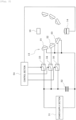
- parts imaging camera unit 11 is attached upward to the parts mounter, and a part picked up by a suction nozzle of the parts mounter is illuminated by coaxial epi-illumination apparatus 12 and side illumination apparatus 13 from below as imaging target object 10, and is imaged by camera 14.
- Camera 14 is configured by using, for example, an imaging element that captures a grayscale image (monochrome image) or a color image.
- Coaxial epi-illumination apparatus 12 includes illumination block 18 on which multiple LEDs 17 (light emitting elements) that emit light in the horizontal direction toward optical axis 16 side of camera 14 are mounted, and half mirror 19 that reflects the illumination light of the illumination block 18 in the direction perpendicular to imaging target object 10 above, and is configured such that the illumination light reflected by half mirror 19 illuminates imaging target object 10 from a direction parallel to optical axis 16 of camera 14.
- a red light emitting diode which is relatively inexpensive and has a feature of low power consumption is used as LED 17 of illumination block 18 of coaxial epi-illumination apparatus 12.
- side illumination apparatus 13 has a configuration in which, for example, three-stages of upper, middle, and lower annular illumination blocks 21, 22, and 23 are arranged in a bowl shape or a polygonal pyramid shape centered on optical axis 16 of camera 14.
- Illumination blocks 21, 22, and 23 of each stage is configured by, for example, assembling multiple LED mounted boards 21b, 22b, and 23b on which multiple number of LEDs 21a, 22a, 23a (light emitting elements) are mounted in a polygonal ring shape such as an octagon, and an irradiation angle of the illumination light of illumination blocks 21, 22, and 23 of each stage with respect to imaging target object 10 is set such that imaging target object 10 positioned on optical axis 16 of camera 14 is irradiated with the illumination light of illumination blocks 21, 22 and 23 of each stage from an oblique direction.
- a blue light emitting diode blue LED
- a red light emitting diode red LED
- Illumination blocks 21, 22, and 23 of each stage of side illumination apparatus 13 are configured to individually lighted, and are configured such that an illumination pattern which is a combination pattern of ON and OFF of lighting illumination blocks 21, 22, and 23 of each stage of side illumination apparatus 13 is switched according to the type (size, shape, material, and the like) of the part which is imaging target object 10, by control section 24 (refer to Fig. 2 ) of the parts mounter.
- Control section 24 of the parts mounter also functions as an image processing device that performs the image processing on the image captured by camera 14 and recognizes imaging target object 10.
- capacitor 32 charge section charged by power supply section 31 via switching elements 33, 34, and 35 such as transistors, respectively.
- capacitor 32 may be one capacitor or may be configured by connecting multiple capacitors in parallel as long as the capacitor has a charging function to be charged by power supply section 31.
- Control section 24 of parts mounter is mainly configured with one or multiple computers (CPUs), selects illumination blocks to be pulse-lighted at the same time from three illumination blocks 21, 22, and 23 of side illumination apparatus 13 according to the type (size, shape, material, and the like) of the part which is imaging target object 10 according to the production program (production job), controls the switching operation (ON/OFF operation) of switching elements 33, 34, and 35 that pulse-light the selected illumination blocks, and also controls the imaging operation of camera 14.
- CPUs central processing unit
- the pulse width (continuous lighting time Ton) of the pulse lighting is set to a pulse width that allows the current necessary for all illumination blocks 21, 22, 23 to flow by the discharge current of one capacitor 32.
- the imaging time (exposure time) of camera 14 is set so as to straddle a predetermined number of pulse-lightings necessary for ensuring the required light receiving amount. That is, the imaging time of camera 14 is set to "cycle of pulse-lighting" ⁇ "the number of pulse-lightings necessary for ensuring the light receiving amount of camera 14".
- the imaging time of camera 14 is "(Ton + Toff) ⁇ 3" which is the time for three cycles of pulse lighting.
- the discharging amount of capacitor 32 decreases. Therefore, the time necessary for charging capacitor 32 is reduced.
- the pulse width and the cycle of pulse lighting are set to constant values regardless of the number of illumination blocks to be pulse-lighted at the same time, as the number of illumination blocks to be pulse-lighted at the same time decreases, among the off-lighting time after the pulse lighting ends, the time that the off-lighting state continues even after the completion of charging of capacitor 32 (the time from the completion of charging of capacitor 32 to the start of the next pulse lighting) increases, and thus, this time becomes a wasteful waiting time and becomes a cause of lengthening the imaging time of camera 14.
- control section 24 of the parts mounter changes the continuous lighting time, which is the pulse width of the pulse lighting according to the number of illumination blocks to be pulse-lighted at the same time among three illumination blocks 21, 22, and 23 of side illumination apparatus 13, and also changes the imaging time of camera 14.
- the continuous lighting time which is the pulse width of the pulse lighting is controlled to be increased as the number of illumination blocks to be pulse-lighted at the same time among three illumination blocks 21, 22, and 23 of side illumination apparatus 13 decreases.
- the continuous lighting time, which is the pulse width of the pulse lighting is increased such that the charge amount of capacitor 32 is used out by one pulse lighting to that small number of illumination blocks.
- the imaging time (exposure time) of camera 14 can be reduced.
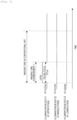
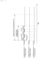
- Fig. 4 is a time chart illustrating a relationship between the pulse width of the pulse lighting and the imaging time when only one illumination block 21 out among three illumination blocks 21, 22, and 23 of side illumination apparatus 13 is pulse-lighted. If the continuous lighting time which is the pulse width of the pulse lighting when all illumination blocks 21, 22, and 23 of side illumination apparatus 13 are pulse-lighted at the same time, is set to Ton [sec] as illustrated in Fig. 3 , and when only one illumination block 21 is pulse-lighted as illustrated in Fig. 4 , control section 24 of the parts mounter sets the continuous lighting time which is the pulse width of the pulse lighting to the continuous lighting time 3 Ton [sec], which is three times the continuous lighting time Ton when three illumination blocks 21, 22, and 23 are pulse-lighted at the same time.
- the imaging time of camera 14 is set to a time same as the continuous lighting time 3Ton [sec], which is the pulse width of one pulse lighting.
- the pulse width and cycle of the pulse lighting were set to constant values regardless of the number of illumination blocks to be pulse-lighted at the same time, as illustrated in Fig. 6 , even when only one illumination block 21 among three illumination blocks 21, 22, and 23 of side illumination apparatus 13 is pulse-lighted, the imaging time of camera 14 becomes the imaging time same as when all illumination blocks 21, 22, and 23 are pulse-lighted at the same time, and thus, the imaging time of camera 14 is significantly longer than that in the present embodiment 1 in Fig. 4 .
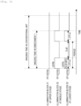
- Fig. 5 is a time chart illustrating a relationship between the pulse width (continuous lighting time) and the cycle of the pulse-lighting, and the imaging time when two illumination blocks 22 and 23 among the are pulse lighted at the same time among three illumination blocks 21, 22, and 23 of side illumination apparatus 13 in the embodiment 1.
- the continuous lighting time when two illumination blocks 22 and 23 are pulse-lighted at the same time is set to the continuous lighting time of 1.5Ton [SEC] which is 1.5 times the continuous lighting time when three illumination blocks 21, 22 and 23 are pulse-lighted at the same time.
- the cycle of pulse-lighting (1.5Ton + Toff) becomes longer by 0.5Ton which is an increase in pulse width compared to the cycle (Ton + Toff) when three illumination blocks 21, 22, and 23 are pulse-lighted at the same time, but the off-lighting time Toff which is the charging time of capacitor 32 does not change.
- side illumination apparatus 13 is divided into three illumination blocks 21, 22, and 23, but the number of illumination blocks may be 2 or 4 or more. Even in such a case, as the number of illumination blocks to be pulse-lighted at the same time among the multiple illumination blocks decreases, the continuous lighting time which is the pulse width of the pulse lighting is increased, and the imaging time of camera 14 is reduced.
- the continuous lighting time which is the pulse width when all of the multiple illumination blocks are pulse-lighted at the same time is Ton [sec]
- the continuous lighting time may be set to Ton ⁇ (N / M) [sec] such that the charge amount of capacitor 32 may be used out by one pulse lighting.
- the continuous lighting time which is the pulse width of the pulse lighting is changed according to the number of illumination blocks to be pulse-lighted at the same time among multiple illumination blocks 21, 22, and 23 of side illumination apparatus 13, and the imaging time of camera 14 is changed. Therefore, for example, as the number of illumination blocks to be pulse-lighted at the same time among multiple illumination blocks 21, 22, 23 of side illumination apparatus 13 decreases, the continuous lighting time can be controlled to be increased. As a result, if the continuous lighting time (pulse width of the pulse lighting) increases, the number of pulse-lightings necessary for ensuring the light receiving amount of camera 14 can be decreased, and thus, it is possible to reduce the imaging time (exposure time) of camera 14.
- the time for imaging can be reduced by stopping the part at the imaging position above camera 14, and the cycle time of part pick up ⁇ imaging ⁇ mounting by the parts mounter can be shortened, and thus, it is possible to improve the productivity.
- control section 24 of the parts mounter changes the cycle of pulse-lighting according to the number of illumination blocks to be pulse-lighted at the same time among multiple illumination blocks 21, 22, and 23 of side illumination apparatus 13 to change the off-lighting time which is the charging time of capacitor 32, and changes the imaging time of camera 14.
- control section 24 of the parts mounter reduces the off-lighting time which is the charging time of capacitor 32, and reduces the imaging time of camera 14.
- the discharging amount of capacitor 32 decreases due to the pulse lighting. Therefore, the off-lighting time which is the charging time of capacitor 32 is controlled to be reduced.
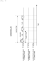
- Fig. 7 is a time chart illustrating a relationship between the pulse width and the cycle of the pulse-lighting, and the imaging time when only one illumination block 21 is pulse-lighted among three illumination blocks 21, 22, and 23 of side illumination apparatus 13. If the continuous lighting time which is the pulse width of pulse lighting when all illumination blocks 21, 22, and 23 of side illumination apparatus 13 are pulse-lighted at the same time is set to Ton [sec], and the off-lighting time is set to Toff [sec] as illustrated in Fig. 3 , and when only one illumination block 21 is pulse-lighted as illustrated in Fig. 7 , the discharging amount of capacitor 32 due to the pulse lighting is reduced to 1/3.
- control section 24 of the parts mounter sets the off-lighting time which is the charging time of capacitor 32 to the off-lighting time Toff / 3 [SEC] which is 1/3 of the off-lighting time when three illumination blocks 21, 22, and 23 are pulse-lighted at the same time.
- Toff / 3 [SEC] which is 1/3 of the off-lighting time when three illumination blocks 21, 22, and 23 are pulse-lighted at the same time.
- Ton which is the pulse width of the pulse lighting
- the number of pulse-lightings necessary for ensuring the light receiving amount of camera 14 does not change.
- the cycle of pulse-lighting is reduced by "Toff ⁇ 2/3" which is the decrease of the off-lighting time, it is possible to reduce the imaging time of camera 14 as much as "(Toff ⁇ 2/3) ⁇ (the number of pulse-lightings - 1)".
- Fig. 8 is a time chart illustrating a relationship between the pulse width and the cycle of the pulse-lighting, and the imaging time when two illumination blocks 21, 22 and 23 of side illumination apparatus 13 are pulse-lighted at the same time among three illumination blocks 21, 22, and 23.
- the off-lighting time which is the charging time of capacitor 32 is set to off-lighting time Toff ⁇ 2/3 [sec] which is 2/3 of the off-lighting time Toff when three illumination blocks 21, 22, and 23 are pulse-lighted at the same time.
- the number of illumination blocks 21, 22, and 23 of side illumination apparatus 13 is not limited to be 3, and may be 2, or equal to or more than 4. Even in this case, as the number of illumination blocks to be pulse-lighted at the same time among the multiple illumination blocks decreases, the off-lighting time which is the charging time of capacitor 32 is reduced and the imaging time of camera 14 is reduced.
- the off-lighting time which is the charging time of capacitor 32 when all of the multiple illumination blocks are pulse-lighted at the same time is set to Toff [sec]
- M is an integer equal to or larger than 1 and equal to smaller than N
- the off-lighting time which is the charging time of capacitor 32 may be set to Toff ⁇ (M / N) [sec].
- multiple illumination blocks 21, 22, and 23 of side illumination apparatus 13 are selectively pulse-lighted by the discharge current of capacitor 32, however, in embodiment 3 illustrated in Fig. 9 , three illumination blocks 21, 22, and 23 of side illumination apparatus 13 and illumination block 18 of coaxial epi-illumination apparatus 12 are connected to capacitor 32 in parallel via switching elements 33 to 36 such as transistors, respectively.
- Control section 24 of the parts mounter selects the illumination blocks to be pulse-lighted at the same time from three illumination blocks 21, 22, and 23 of side illumination apparatus 13 and illumination block 18 of coaxial epi-illumination apparatus 12 according to the type (size, shape, material, and the like) of the part that is imaging target object 10 according to the production program (production job), controls the switching operation (ON/OFF operation) of switching elements 33 to 36 that pulse-light the selected illumination blocks, and also controls the imaging operation of camera 14.
- illumination block 18 of coaxial epi-illumination apparatus 12 may be divided into multiple illumination blocks as in side illumination apparatus 13.
- control section 24 of the parts mounter changes the continuous lighting time which is the pulse width of the pulse lighting according to the number of illumination blocks to be pulse-lighted at the same time among multiple illumination blocks 21, 22, 23, and 18 of side illumination apparatus 13 and coaxial epi-illumination apparatus 12, or changes the off-lighting time which is the charging time of capacitor 32 by changing the cycle of pulse-lighting. For example, by increasing the continuous lighting time which is the pulse width of pulse lighting, and by decreasing the off-lighting time which is the charging time of capacitor 32 as the number of illumination blocks to be pulse-lighted at the same time decreases, the imaging time of camera 14 is controlled to be reduced.
- the method of reducing the imaging time of parts imaging camera 14, however, for the camera for marking the reference position mark on the circuit board also, by changing the continuous lighting time which is the pulse width of pulse lighting according to the number of illumination blocks to be pulse-lighted at the same time among multiple illumination blocks or by changing the off-lighting time which is the charging time of the capacitor using the same method as in the embodiment 1 or embodiment 2 described above, the imaging time of the mark imaging camera for mark imaging may be reduced.
- the present invention is not limited to the camera unit mounted on the parts mounter, and it is needless to say that various changes can be made within the scope of the claims, such as can be applied to various industrial machines mounted with an imaging illumination apparatus that selectively pulse-lights multiple illumination blocks connected to the charge section in parallel.
Landscapes
- Physics & Mathematics (AREA)
- General Physics & Mathematics (AREA)
- Engineering & Computer Science (AREA)
- Multimedia (AREA)
- Theoretical Computer Science (AREA)
- Studio Devices (AREA)
- Supply And Installment Of Electrical Components (AREA)
- Stroboscope Apparatuses (AREA)
- Circuit Arrangement For Electric Light Sources In General (AREA)
- Image Input (AREA)
Claims (8)
- Bilderzeugungs-Beleuchtungsvorrichtung, die so konfiguriert ist, dass sie ein Bilderzeugungs-Zielobjekt (10) beleuchtet, dessen Bild von einer für Bilderkennung eingesetzten Kamera (14) erzeugt werden soll, wobei die Vorrichtung umfasst:mehrere Beleuchtungsblöcke (21, 22, 23), die so konfiguriert sind, dass sie einzeln zum Leuchten gebracht werden;einen Ladeabschnitt (32), der so konfiguriert ist, dass er von einem Stromversorgungsabschnitt (31) geladen wird;mehrere Schaltelemente (33-36), die so konfiguriert sind, dass sie parallel mit dem Ladeabschnitt verbunden sind,und den Ladeabschnitt durch eine AN-Betätigung entladen und die mehreren Beleuchtungsblöcke mit dem entladenen Strom einzeln impulsartig zum Leuchten bringen; sowieeinen Steuerungsabschnitt (24), der so konfiguriert ist, dass er die zur gleichen Zeit impulsartig zum Leuchten zu bringenden Beleuchtungsblöcke aus den mehreren Beleuchtungsblöcken auswählt,eine Schaltbetätigung der Schaltelemente steuert, die die ausgewählten Beleuchtungsblöcke impulsartig zum Leuchten bringen, und eine Bilderzeugungs-Betätigung der Kamera steuert,wobei der Steuerungsabschnitt so konfiguriert ist, dass er eine durchgehende Leucht-Zeit, die eine Impulsbreite impulsartigen Aufleuchtens ist, entsprechend der Anzahl zur gleichen Zeit impulsartig zum Leuchten zu bringender Beleuchtungsblöcke der mehreren Beleuchtungsblöcke ändert und eine Bilderzeugungs-Zeit der Kamera ändert, wobei der Steuerungsabschnitt so konfiguriert ist, dass er die durchgehende Leucht-Zeit verlängert und die Bilderzeugungs-Zeit der Kamera verkürzt, wenn die Anzahl zur gleichen Zeit impulsartig zum Leuchten zu bringender Beleuchtungsblöcke der mehreren Beleuchtungsblöcke abnimmt.
- Bilderzeugungs-Beleuchtungsvorrichtung nach Anspruch 1,
wobei der Steuerungsabschnitt so konfiguriert ist, dass er die durchgehende Leucht-Zeit auf Ton × (N/M) [s] einstellt, wenn die durchgehende Leucht-Zeit, zu der alle der mehreren Beleuchtungsblöcke zur gleichen Zeit impulsartig zum Leuchten gebracht werden, Ton [s] ist und die Anzahl mehrerer Beleuchtungsblöcke N ist (wobei N eine ganze Zahl gleich oder größer als 2 ist), und die zur gleichen Zeit impulsartig zum Leuchten zu bringende Anzahl von Beleuchtungsblöcken der mehreren Beleuchtungsblöcke M ist (wobei M eine ganze Zahl gleich oder größer als 1 und gleich oder kleiner als N ist). - Bilderzeugungs-Beleuchtungsvorrichtung, die so konfiguriert ist, dass sie ein Bilderzeugungs-Zielobjekt (10) beleuchtet, dessen Bild von einer für Bilderkennung eingesetzten Kamera (14) erzeugt werden soll, wobei die Vorrichtung umfasst:mehrere Beleuchtungsblöcke (21, 22, 23), die so konfiguriert sind, dass sie einzeln zum Leuchten gebracht werden;einen Ladeabschnitt (32), der so konfiguriert ist, dass er von einem Stromversorgungsabschnitt (31) geladen wird;mehrere Schaltelemente (33-36), die so konfiguriert sind, dass sie parallel mit dem Ladeabschnitt verbunden sind, und den Ladeabschnitt durch eine AN-Betätigung entladen und die mehreren Beleuchtungsblöcke mit dem entladenen Strom einzeln impulsartig zum Leuchten bringen; sowie einen Steuerungsabschnitt (24), der so konfiguriert ist, dass er die zur gleichen Zeit impulsartig zum Leuchten zu bringenden Beleuchtungsblöcke aus den mehreren Beleuchtungsblöcken auswählt, eine Schaltbetätigung der Schaltelemente steuert, die die ausgewählten Beleuchtungsblöcke impulsartig zum Leuchten bringen, und eine Bilderzeugungs-Betätigung der Kamera steuert,wobei der Steuerabschnitt so konfiguriert ist, dass er einen Zyklus impulsartigen Leuchtens entsprechend der Anzahl zur gleichen Zeit impulsartig zum Leuchten zu bringender Beleuchtungsblöcke der mehreren Beleuchtungsblöcke ändert, und eine Zeit ohne Leuchten ändert, die eine Ladezeit des Ladeabschnitts ist, und eine Bilderzeugungs-Zeit der Kamera ändert, wobei der Steuerungsabschnitt so konfiguriert ist, dass er die Zeit ohne Leuchten verkürzt und die Bilderzeugungs-Zeit der Kamera verkürzt, wenn die Anzahl zur gleichen Zeit impulsartig zum Leuchten zu bringender Beleuchtungsblöcke der mehreren Beleuchtungsblöcke abnimmt.
- Bilderzeugungs-Beleuchtungsvorrichtung nach Anspruch 3, wobei der Steuerungsabschnitt so konfiguriert ist, dass er die Zeit ohne Leuchten auf Toff × (M/N) [s] einstellt, wenn die Zeit ohne Leuchten, zu der alle der mehreren Beleuchtungsblöcke zur gleichen Zeit impulsartig zum Leuchten gebracht werden, Toff [s] ist und die Anzahl mehrerer Beleuchtungsblöcke N ist (wobei N eine ganze Zahl gleich oder größer als 2 ist), und die Anzahl zur gleichen Zeit impulsartig zum Leuchten zu bringender Beleuchtungsblöcke der mehreren Beleuchtungsblöcke M ist (wobei M eine ganze Zahl gleich oder größer als 1 und gleich oder kleiner als N ist).
- Bilderzeugungs-Beleuchtungsvorrichtung nach einem der Ansprüche 1 bis 4, wobei die mehreren Beleuchtungsblöcke konzentrisch um eine optische Achse (16) der Kamera herum angeordnet sind, und
der Steuerungsabschnitt so konfiguriert ist, dass er einen Bestrahlungswinkel eines Beleuchtungslichtes auf das Bilderzeugungs-Zielobjekt ändert, indem er die impulsartig zum Leuchten zu bringenden Beleuchtungsblöcke aus den mehreren Beleuchtungsblöcken auswählt. - Bilderzeugungs-Beleuchtungsvorrichtung nach einem der Ansprüche 1 bis 4, wobei die mehreren Beleuchtungsblöcke mit zwei oder mehr als zwei Beleuchtungsblöcken, die das Bilderzeugungs-Zielobjekt in einer Richtung schräg zu einer optischen Achse der Kamera beleuchten, sowie mit wenigstens einem Beleuchtungsblock konfiguriert sind, der das Bilderzeugungs-Zielobjekt in einer Richtung parallel zu der optischen Achse der Kamera beleuchtet.
- Bilderzeugungs-Beleuchtungsvorrichtung nach einem der Ansprüche 1 bis 6, wobei mehrere LED (17) als lichtemittierende Elemente an jedem der mehreren Beleuchtungsblöcke angebracht sind.
- Vorrichtung zum Montieren von Teilen, an der die Bilderzeugungs-Beleuchtungsvorrichtung nach einem der Ansprüche 1 bis 7 installiert ist, wobei die Vorrichtung zum Montieren von Teilen umfasst:eine Saugdüse,wobei die Vorrichtung zum Montieren von Teilen so konfiguriert ist, dass sie ein Beleuchtungsmuster, das ein Kombinationsmuster aus leuchtenden und nicht leuchtenden der mehreren Beleuchtungsblöcke ist, entsprechend einem Typ eines Teils umschaltet, um ein Bild des Teils als dem von der Saugdüse aufgenommenen Bilderzeugungs-Zielobjekt unter Einsatz der Kamera zu erzeugen.
Applications Claiming Priority (1)
| Application Number | Priority Date | Filing Date | Title |
|---|---|---|---|
| PCT/JP2018/033114 WO2020049703A1 (ja) | 2018-09-06 | 2018-09-06 | 撮像用照明装置および部品実装機 |
Publications (3)
| Publication Number | Publication Date |
|---|---|
| EP3848751A1 EP3848751A1 (de) | 2021-07-14 |
| EP3848751A4 EP3848751A4 (de) | 2021-08-25 |
| EP3848751B1 true EP3848751B1 (de) | 2024-01-10 |
Family
ID=69722476
Family Applications (1)
| Application Number | Title | Priority Date | Filing Date |
|---|---|---|---|
| EP18932729.9A Active EP3848751B1 (de) | 2018-09-06 | 2018-09-06 | Bildgebungsbeleuchtungsvorrichtung und teilehalter |
Country Status (4)
| Country | Link |
|---|---|
| EP (1) | EP3848751B1 (de) |
| JP (1) | JP6893287B2 (de) |
| CN (1) | CN112602380B (de) |
| WO (1) | WO2020049703A1 (de) |
Family Cites Families (14)
| Publication number | Priority date | Publication date | Assignee | Title |
|---|---|---|---|---|
| US7740371B1 (en) * | 1998-03-19 | 2010-06-22 | Charles A. Lemaire | Method and apparatus for pulsed L.E.D. illumination for a camera |
| JP3733800B2 (ja) | 1999-09-20 | 2006-01-11 | 松下電器産業株式会社 | 電子部品実装装置における電子部品認識装置 |
| JP4558224B2 (ja) * | 2001-02-09 | 2010-10-06 | オリンパス株式会社 | ストロボ装置 |
| JP2004145142A (ja) * | 2002-10-25 | 2004-05-20 | Make Softwear:Kk | 写真自動販売装置 |
| JP4355500B2 (ja) * | 2003-01-31 | 2009-11-04 | 富士フイルム株式会社 | デジタルカメラ |
| JP4381764B2 (ja) * | 2003-09-29 | 2009-12-09 | ヤマハ発動機株式会社 | 撮像装置及び同装置を搭載した被撮像物移動装置 |
| US7127159B2 (en) * | 2004-07-29 | 2006-10-24 | Mitutoyo Corporation | Strobe illumination |
| JP2006294977A (ja) | 2005-04-13 | 2006-10-26 | Yamaha Motor Co Ltd | 照明装置、部品認識装置、表面実装機および部品試験装置 |
| JP2009110784A (ja) | 2007-10-30 | 2009-05-21 | Panasonic Corp | Led照明装置および時限作動回路 |
| JP5074278B2 (ja) * | 2008-04-21 | 2012-11-14 | オリンパス株式会社 | 照明装置および照明撮像装置 |
| JP5456518B2 (ja) * | 2010-02-26 | 2014-04-02 | 三洋電機株式会社 | 照明制御装置 |
| JP5474653B2 (ja) * | 2010-05-07 | 2014-04-16 | オリンパスイメージング株式会社 | 撮像装置及び撮像方法 |
| JP6954925B2 (ja) * | 2017-01-06 | 2021-10-27 | 株式会社Fuji | 部品実装機の撮像用照明装置 |
| WO2018134862A1 (ja) * | 2017-01-17 | 2018-07-26 | ヤマハ発動機株式会社 | 撮像装置及びこれを用いた表面実装機 |
-
2018
- 2018-09-06 JP JP2020540959A patent/JP6893287B2/ja active Active
- 2018-09-06 EP EP18932729.9A patent/EP3848751B1/de active Active
- 2018-09-06 CN CN201880096911.5A patent/CN112602380B/zh active Active
- 2018-09-06 WO PCT/JP2018/033114 patent/WO2020049703A1/ja not_active Ceased
Also Published As
| Publication number | Publication date |
|---|---|
| EP3848751A1 (de) | 2021-07-14 |
| WO2020049703A1 (ja) | 2020-03-12 |
| CN112602380B (zh) | 2023-05-16 |
| JP6893287B2 (ja) | 2021-06-23 |
| EP3848751A4 (de) | 2021-08-25 |
| CN112602380A (zh) | 2021-04-02 |
| JPWO2020049703A1 (ja) | 2021-02-18 |
Similar Documents
| Publication | Publication Date | Title |
|---|---|---|
| EP3567425B1 (de) | Beleuchtungsvorrichtung zur bilderfassung | |
| CN102714933B (zh) | 部件安装装置、成像用的照明装置和照明方法 | |
| CN109387510B (zh) | 图像处理系统、设定辅助装置及计算机可读记录介质 | |
| WO2013061749A1 (ja) | 照明装置及びそれを用いた照明器具 | |
| EP3576499B1 (de) | Lichtansteuerungsvorrichtung und lichtansteuerungsverfahren dafür | |
| EP2530519B1 (de) | Lichtemittierendes halbleiterelement und blitzlichtvorrichtung | |
| CN116013916B (zh) | 一种led灯珠封装模组及显示屏控制系统 | |
| JPH04241476A (ja) | 照明装置 | |
| JPH1187774A (ja) | Led表示装置及び半導体装置 | |
| CN102668741B (zh) | 组件安装装置、用于成像的照明装置、以及照明方法 | |
| JPH1140983A (ja) | 基板マーク認識装置 | |
| EP3848751A1 (de) | Bildgebungsbeleuchtungsvorrichtung und teilehalter | |
| CN110536812A (zh) | 车辆用灯具 | |
| US8148908B2 (en) | Power supply control device for lamp | |
| CN115938289B (zh) | 基于静态驱动电路的显示屏亮度一致性的调节方法 | |
| EP3863391B1 (de) | Kamera zur aufnahme von komponentenbildern und bestückungsmaschine | |
| JPH10208017A (ja) | 画像認識用照明装置及び方法 | |
| US20050099528A1 (en) | Mobile terminal device with a camera, illumination control method thereof and program for illumination control | |
| KR101187837B1 (ko) | 제어 드라이브 칩이 내장된 엘이디램프 및 그 제조방법 | |
| JP2006310402A (ja) | 光源基板製造方法、光源基板、バックライト装置、液晶ディスプレイ装置、調整装置 | |
| CN111935368B (zh) | 内置红外灯和白光灯的摄像机 | |
| CN109828524B (zh) | 可编程控制系统及方法 | |
| WO2016159407A1 (ko) | 색온도 조절이 가능한 엘이디 조명장치 | |
| CN108235493B (zh) | 光源调节装置及其光源控制器 | |
| CN115966165B (zh) | 静态led显示屏安装调试方法 |
Legal Events
| Date | Code | Title | Description |
|---|---|---|---|
| STAA | Information on the status of an ep patent application or granted ep patent |
Free format text: STATUS: THE INTERNATIONAL PUBLICATION HAS BEEN MADE |
|
| PUAI | Public reference made under article 153(3) epc to a published international application that has entered the european phase |
Free format text: ORIGINAL CODE: 0009012 |
|
| STAA | Information on the status of an ep patent application or granted ep patent |
Free format text: STATUS: REQUEST FOR EXAMINATION WAS MADE |
|
| 17P | Request for examination filed |
Effective date: 20210210 |
|
| AK | Designated contracting states |
Kind code of ref document: A1 Designated state(s): AL AT BE BG CH CY CZ DE DK EE ES FI FR GB GR HR HU IE IS IT LI LT LU LV MC MK MT NL NO PL PT RO RS SE SI SK SM TR |
|
| REG | Reference to a national code |
Ref country code: DE Ref legal event code: R079 Free format text: PREVIOUS MAIN CLASS: G03B0007260000 Ipc: G03B0015030000 Ref document number: 602018064148 Country of ref document: DE |
|
| A4 | Supplementary search report drawn up and despatched |
Effective date: 20210726 |
|
| RIC1 | Information provided on ipc code assigned before grant |
Ipc: G03B 15/03 20210101AFI20210720BHEP Ipc: G03B 15/05 20210101ALI20210720BHEP Ipc: H05K 13/08 20060101ALI20210720BHEP Ipc: G03B 7/17 20210101ALI20210720BHEP Ipc: G06K 9/20 20060101ALI20210720BHEP |
|
| DAV | Request for validation of the european patent (deleted) | ||
| DAX | Request for extension of the european patent (deleted) | ||
| P01 | Opt-out of the competence of the unified patent court (upc) registered |
Effective date: 20230328 |
|
| GRAP | Despatch of communication of intention to grant a patent |
Free format text: ORIGINAL CODE: EPIDOSNIGR1 |
|
| STAA | Information on the status of an ep patent application or granted ep patent |
Free format text: STATUS: GRANT OF PATENT IS INTENDED |
|
| RIC1 | Information provided on ipc code assigned before grant |
Ipc: G06V 10/141 20220101ALI20230726BHEP Ipc: G03B 15/07 20210101ALI20230726BHEP Ipc: G03B 7/17 20210101ALI20230726BHEP Ipc: G03B 15/05 20210101ALI20230726BHEP Ipc: G03B 15/03 20210101AFI20230726BHEP |
|
| INTG | Intention to grant announced |
Effective date: 20230829 |
|
| GRAS | Grant fee paid |
Free format text: ORIGINAL CODE: EPIDOSNIGR3 |
|
| GRAA | (expected) grant |
Free format text: ORIGINAL CODE: 0009210 |
|
| STAA | Information on the status of an ep patent application or granted ep patent |
Free format text: STATUS: THE PATENT HAS BEEN GRANTED |
|
| AK | Designated contracting states |
Kind code of ref document: B1 Designated state(s): AL AT BE BG CH CY CZ DE DK EE ES FI FR GB GR HR HU IE IS IT LI LT LU LV MC MK MT NL NO PL PT RO RS SE SI SK SM TR |
|
| REG | Reference to a national code |
Ref country code: GB Ref legal event code: FG4D |
|
| REG | Reference to a national code |
Ref country code: CH Ref legal event code: EP |
|
| REG | Reference to a national code |
Ref country code: DE Ref legal event code: R096 Ref document number: 602018064148 Country of ref document: DE |
|
| REG | Reference to a national code |
Ref country code: IE Ref legal event code: FG4D |
|
| REG | Reference to a national code |
Ref country code: LT Ref legal event code: MG9D |
|
| REG | Reference to a national code |
Ref country code: NL Ref legal event code: MP Effective date: 20240110 |
|
| REG | Reference to a national code |
Ref country code: AT Ref legal event code: MK05 Ref document number: 1649368 Country of ref document: AT Kind code of ref document: T Effective date: 20240110 |
|
| PG25 | Lapsed in a contracting state [announced via postgrant information from national office to epo] |
Ref country code: NL Free format text: LAPSE BECAUSE OF FAILURE TO SUBMIT A TRANSLATION OF THE DESCRIPTION OR TO PAY THE FEE WITHIN THE PRESCRIBED TIME-LIMIT Effective date: 20240110 |
|
| PG25 | Lapsed in a contracting state [announced via postgrant information from national office to epo] |
Ref country code: NL Free format text: LAPSE BECAUSE OF FAILURE TO SUBMIT A TRANSLATION OF THE DESCRIPTION OR TO PAY THE FEE WITHIN THE PRESCRIBED TIME-LIMIT Effective date: 20240110 |
|
| PG25 | Lapsed in a contracting state [announced via postgrant information from national office to epo] |
Ref country code: IS Free format text: LAPSE BECAUSE OF FAILURE TO SUBMIT A TRANSLATION OF THE DESCRIPTION OR TO PAY THE FEE WITHIN THE PRESCRIBED TIME-LIMIT Effective date: 20240510 |
|
| PG25 | Lapsed in a contracting state [announced via postgrant information from national office to epo] |
Ref country code: LT Free format text: LAPSE BECAUSE OF FAILURE TO SUBMIT A TRANSLATION OF THE DESCRIPTION OR TO PAY THE FEE WITHIN THE PRESCRIBED TIME-LIMIT Effective date: 20240110 |
|
| PG25 | Lapsed in a contracting state [announced via postgrant information from national office to epo] |
Ref country code: GR Free format text: LAPSE BECAUSE OF FAILURE TO SUBMIT A TRANSLATION OF THE DESCRIPTION OR TO PAY THE FEE WITHIN THE PRESCRIBED TIME-LIMIT Effective date: 20240411 |
|
| PG25 | Lapsed in a contracting state [announced via postgrant information from national office to epo] |
Ref country code: HR Free format text: LAPSE BECAUSE OF FAILURE TO SUBMIT A TRANSLATION OF THE DESCRIPTION OR TO PAY THE FEE WITHIN THE PRESCRIBED TIME-LIMIT Effective date: 20240110 Ref country code: RS Free format text: LAPSE BECAUSE OF FAILURE TO SUBMIT A TRANSLATION OF THE DESCRIPTION OR TO PAY THE FEE WITHIN THE PRESCRIBED TIME-LIMIT Effective date: 20240410 |
|
| PG25 | Lapsed in a contracting state [announced via postgrant information from national office to epo] |
Ref country code: ES Free format text: LAPSE BECAUSE OF FAILURE TO SUBMIT A TRANSLATION OF THE DESCRIPTION OR TO PAY THE FEE WITHIN THE PRESCRIBED TIME-LIMIT Effective date: 20240110 |
|
| PG25 | Lapsed in a contracting state [announced via postgrant information from national office to epo] |
Ref country code: AT Free format text: LAPSE BECAUSE OF FAILURE TO SUBMIT A TRANSLATION OF THE DESCRIPTION OR TO PAY THE FEE WITHIN THE PRESCRIBED TIME-LIMIT Effective date: 20240110 |
|
| PG25 | Lapsed in a contracting state [announced via postgrant information from national office to epo] |
Ref country code: RS Free format text: LAPSE BECAUSE OF FAILURE TO SUBMIT A TRANSLATION OF THE DESCRIPTION OR TO PAY THE FEE WITHIN THE PRESCRIBED TIME-LIMIT Effective date: 20240410 Ref country code: NO Free format text: LAPSE BECAUSE OF FAILURE TO SUBMIT A TRANSLATION OF THE DESCRIPTION OR TO PAY THE FEE WITHIN THE PRESCRIBED TIME-LIMIT Effective date: 20240410 Ref country code: LT Free format text: LAPSE BECAUSE OF FAILURE TO SUBMIT A TRANSLATION OF THE DESCRIPTION OR TO PAY THE FEE WITHIN THE PRESCRIBED TIME-LIMIT Effective date: 20240110 Ref country code: IS Free format text: LAPSE BECAUSE OF FAILURE TO SUBMIT A TRANSLATION OF THE DESCRIPTION OR TO PAY THE FEE WITHIN THE PRESCRIBED TIME-LIMIT Effective date: 20240510 Ref country code: HR Free format text: LAPSE BECAUSE OF FAILURE TO SUBMIT A TRANSLATION OF THE DESCRIPTION OR TO PAY THE FEE WITHIN THE PRESCRIBED TIME-LIMIT Effective date: 20240110 Ref country code: GR Free format text: LAPSE BECAUSE OF FAILURE TO SUBMIT A TRANSLATION OF THE DESCRIPTION OR TO PAY THE FEE WITHIN THE PRESCRIBED TIME-LIMIT Effective date: 20240411 Ref country code: ES Free format text: LAPSE BECAUSE OF FAILURE TO SUBMIT A TRANSLATION OF THE DESCRIPTION OR TO PAY THE FEE WITHIN THE PRESCRIBED TIME-LIMIT Effective date: 20240110 Ref country code: BG Free format text: LAPSE BECAUSE OF FAILURE TO SUBMIT A TRANSLATION OF THE DESCRIPTION OR TO PAY THE FEE WITHIN THE PRESCRIBED TIME-LIMIT Effective date: 20240110 Ref country code: AT Free format text: LAPSE BECAUSE OF FAILURE TO SUBMIT A TRANSLATION OF THE DESCRIPTION OR TO PAY THE FEE WITHIN THE PRESCRIBED TIME-LIMIT Effective date: 20240110 |
|
| PG25 | Lapsed in a contracting state [announced via postgrant information from national office to epo] |
Ref country code: PL Free format text: LAPSE BECAUSE OF FAILURE TO SUBMIT A TRANSLATION OF THE DESCRIPTION OR TO PAY THE FEE WITHIN THE PRESCRIBED TIME-LIMIT Effective date: 20240110 Ref country code: PT Free format text: LAPSE BECAUSE OF FAILURE TO SUBMIT A TRANSLATION OF THE DESCRIPTION OR TO PAY THE FEE WITHIN THE PRESCRIBED TIME-LIMIT Effective date: 20240510 |
|
| PG25 | Lapsed in a contracting state [announced via postgrant information from national office to epo] |
Ref country code: SE Free format text: LAPSE BECAUSE OF FAILURE TO SUBMIT A TRANSLATION OF THE DESCRIPTION OR TO PAY THE FEE WITHIN THE PRESCRIBED TIME-LIMIT Effective date: 20240110 Ref country code: PT Free format text: LAPSE BECAUSE OF FAILURE TO SUBMIT A TRANSLATION OF THE DESCRIPTION OR TO PAY THE FEE WITHIN THE PRESCRIBED TIME-LIMIT Effective date: 20240510 Ref country code: PL Free format text: LAPSE BECAUSE OF FAILURE TO SUBMIT A TRANSLATION OF THE DESCRIPTION OR TO PAY THE FEE WITHIN THE PRESCRIBED TIME-LIMIT Effective date: 20240110 Ref country code: LV Free format text: LAPSE BECAUSE OF FAILURE TO SUBMIT A TRANSLATION OF THE DESCRIPTION OR TO PAY THE FEE WITHIN THE PRESCRIBED TIME-LIMIT Effective date: 20240110 |
|
| PG25 | Lapsed in a contracting state [announced via postgrant information from national office to epo] |
Ref country code: DK Free format text: LAPSE BECAUSE OF FAILURE TO SUBMIT A TRANSLATION OF THE DESCRIPTION OR TO PAY THE FEE WITHIN THE PRESCRIBED TIME-LIMIT Effective date: 20240110 |
|
| REG | Reference to a national code |
Ref country code: DE Ref legal event code: R097 Ref document number: 602018064148 Country of ref document: DE |
|
| PG25 | Lapsed in a contracting state [announced via postgrant information from national office to epo] |
Ref country code: SM Free format text: LAPSE BECAUSE OF FAILURE TO SUBMIT A TRANSLATION OF THE DESCRIPTION OR TO PAY THE FEE WITHIN THE PRESCRIBED TIME-LIMIT Effective date: 20240110 |
|
| PG25 | Lapsed in a contracting state [announced via postgrant information from national office to epo] |
Ref country code: CZ Free format text: LAPSE BECAUSE OF FAILURE TO SUBMIT A TRANSLATION OF THE DESCRIPTION OR TO PAY THE FEE WITHIN THE PRESCRIBED TIME-LIMIT Effective date: 20240110 Ref country code: EE Free format text: LAPSE BECAUSE OF FAILURE TO SUBMIT A TRANSLATION OF THE DESCRIPTION OR TO PAY THE FEE WITHIN THE PRESCRIBED TIME-LIMIT Effective date: 20240110 |
|
| PG25 | Lapsed in a contracting state [announced via postgrant information from national office to epo] |
Ref country code: SK Free format text: LAPSE BECAUSE OF FAILURE TO SUBMIT A TRANSLATION OF THE DESCRIPTION OR TO PAY THE FEE WITHIN THE PRESCRIBED TIME-LIMIT Effective date: 20240110 |
|
| PG25 | Lapsed in a contracting state [announced via postgrant information from national office to epo] |
Ref country code: SM Free format text: LAPSE BECAUSE OF FAILURE TO SUBMIT A TRANSLATION OF THE DESCRIPTION OR TO PAY THE FEE WITHIN THE PRESCRIBED TIME-LIMIT Effective date: 20240110 Ref country code: SK Free format text: LAPSE BECAUSE OF FAILURE TO SUBMIT A TRANSLATION OF THE DESCRIPTION OR TO PAY THE FEE WITHIN THE PRESCRIBED TIME-LIMIT Effective date: 20240110 Ref country code: RO Free format text: LAPSE BECAUSE OF FAILURE TO SUBMIT A TRANSLATION OF THE DESCRIPTION OR TO PAY THE FEE WITHIN THE PRESCRIBED TIME-LIMIT Effective date: 20240110 Ref country code: EE Free format text: LAPSE BECAUSE OF FAILURE TO SUBMIT A TRANSLATION OF THE DESCRIPTION OR TO PAY THE FEE WITHIN THE PRESCRIBED TIME-LIMIT Effective date: 20240110 Ref country code: DK Free format text: LAPSE BECAUSE OF FAILURE TO SUBMIT A TRANSLATION OF THE DESCRIPTION OR TO PAY THE FEE WITHIN THE PRESCRIBED TIME-LIMIT Effective date: 20240110 Ref country code: CZ Free format text: LAPSE BECAUSE OF FAILURE TO SUBMIT A TRANSLATION OF THE DESCRIPTION OR TO PAY THE FEE WITHIN THE PRESCRIBED TIME-LIMIT Effective date: 20240110 |
|
| PLBE | No opposition filed within time limit |
Free format text: ORIGINAL CODE: 0009261 |
|
| STAA | Information on the status of an ep patent application or granted ep patent |
Free format text: STATUS: NO OPPOSITION FILED WITHIN TIME LIMIT |
|
| PG25 | Lapsed in a contracting state [announced via postgrant information from national office to epo] |
Ref country code: IT Free format text: LAPSE BECAUSE OF FAILURE TO SUBMIT A TRANSLATION OF THE DESCRIPTION OR TO PAY THE FEE WITHIN THE PRESCRIBED TIME-LIMIT Effective date: 20240110 |
|
| 26N | No opposition filed |
Effective date: 20241011 |
|
| PG25 | Lapsed in a contracting state [announced via postgrant information from national office to epo] |
Ref country code: IT Free format text: LAPSE BECAUSE OF FAILURE TO SUBMIT A TRANSLATION OF THE DESCRIPTION OR TO PAY THE FEE WITHIN THE PRESCRIBED TIME-LIMIT Effective date: 20240110 |
|
| PG25 | Lapsed in a contracting state [announced via postgrant information from national office to epo] |
Ref country code: MC Free format text: LAPSE BECAUSE OF FAILURE TO SUBMIT A TRANSLATION OF THE DESCRIPTION OR TO PAY THE FEE WITHIN THE PRESCRIBED TIME-LIMIT Effective date: 20240110 Ref country code: SI Free format text: LAPSE BECAUSE OF FAILURE TO SUBMIT A TRANSLATION OF THE DESCRIPTION OR TO PAY THE FEE WITHIN THE PRESCRIBED TIME-LIMIT Effective date: 20240110 |
|
| REG | Reference to a national code |
Ref country code: CH Ref legal event code: PL |
|
| PG25 | Lapsed in a contracting state [announced via postgrant information from national office to epo] |
Ref country code: LU Free format text: LAPSE BECAUSE OF NON-PAYMENT OF DUE FEES Effective date: 20240906 |
|
| GBPC | Gb: european patent ceased through non-payment of renewal fee |
Effective date: 20240906 |
|
| PG25 | Lapsed in a contracting state [announced via postgrant information from national office to epo] |
Ref country code: GB Free format text: LAPSE BECAUSE OF NON-PAYMENT OF DUE FEES Effective date: 20240906 |
|
| REG | Reference to a national code |
Ref country code: BE Ref legal event code: MM Effective date: 20240930 |
|
| PG25 | Lapsed in a contracting state [announced via postgrant information from national office to epo] |
Ref country code: BE Free format text: LAPSE BECAUSE OF NON-PAYMENT OF DUE FEES Effective date: 20240930 |
|
| PG25 | Lapsed in a contracting state [announced via postgrant information from national office to epo] |
Ref country code: FR Free format text: LAPSE BECAUSE OF NON-PAYMENT OF DUE FEES Effective date: 20240930 |
|
| PG25 | Lapsed in a contracting state [announced via postgrant information from national office to epo] |
Ref country code: CH Free format text: LAPSE BECAUSE OF NON-PAYMENT OF DUE FEES Effective date: 20240930 |
|
| PG25 | Lapsed in a contracting state [announced via postgrant information from national office to epo] |
Ref country code: IE Free format text: LAPSE BECAUSE OF NON-PAYMENT OF DUE FEES Effective date: 20240906 |
|
| PG25 | Lapsed in a contracting state [announced via postgrant information from national office to epo] |
Ref country code: FI Free format text: LAPSE BECAUSE OF FAILURE TO SUBMIT A TRANSLATION OF THE DESCRIPTION OR TO PAY THE FEE WITHIN THE PRESCRIBED TIME-LIMIT Effective date: 20240110 |
|
| PGFP | Annual fee paid to national office [announced via postgrant information from national office to epo] |
Ref country code: DE Payment date: 20250730 Year of fee payment: 8 |
|
| PG25 | Lapsed in a contracting state [announced via postgrant information from national office to epo] |
Ref country code: CY Free format text: LAPSE BECAUSE OF FAILURE TO SUBMIT A TRANSLATION OF THE DESCRIPTION OR TO PAY THE FEE WITHIN THE PRESCRIBED TIME-LIMIT; INVALID AB INITIO Effective date: 20180906 |
|
| PG25 | Lapsed in a contracting state [announced via postgrant information from national office to epo] |
Ref country code: HU Free format text: LAPSE BECAUSE OF FAILURE TO SUBMIT A TRANSLATION OF THE DESCRIPTION OR TO PAY THE FEE WITHIN THE PRESCRIBED TIME-LIMIT; INVALID AB INITIO Effective date: 20180906 |