EP3848749A1 - Pénalité de hauteur réduite pour appareil photo plié - Google Patents
Pénalité de hauteur réduite pour appareil photo plié Download PDFInfo
- Publication number
- EP3848749A1 EP3848749A1 EP21159192.0A EP21159192A EP3848749A1 EP 3848749 A1 EP3848749 A1 EP 3848749A1 EP 21159192 A EP21159192 A EP 21159192A EP 3848749 A1 EP3848749 A1 EP 3848749A1
- Authority
- EP
- European Patent Office
- Prior art keywords
- lens
- actuator
- height
- ois
- assembly
- Prior art date
- Legal status (The legal status is an assumption and is not a legal conclusion. Google has not performed a legal analysis and makes no representation as to the accuracy of the status listed.)
- Pending
Links
- 230000003287 optical effect Effects 0.000 claims abstract description 81
- 230000006641 stabilisation Effects 0.000 claims abstract description 11
- 238000011105 stabilization Methods 0.000 claims abstract description 11
- 230000008901 benefit Effects 0.000 description 8
- 230000009467 reduction Effects 0.000 description 6
- 239000004033 plastic Substances 0.000 description 4
- 238000000429 assembly Methods 0.000 description 3
- 230000007246 mechanism Effects 0.000 description 3
- 230000009977 dual effect Effects 0.000 description 2
- 238000005516 engineering process Methods 0.000 description 2
- 239000011521 glass Substances 0.000 description 2
- 238000010348 incorporation Methods 0.000 description 2
- 239000000463 material Substances 0.000 description 2
- 238000000034 method Methods 0.000 description 2
- 238000005096 rolling process Methods 0.000 description 2
- RYGMFSIKBFXOCR-UHFFFAOYSA-N Copper Chemical compound [Cu] RYGMFSIKBFXOCR-UHFFFAOYSA-N 0.000 description 1
- 229910052802 copper Inorganic materials 0.000 description 1
- 239000010949 copper Substances 0.000 description 1
- 239000002184 metal Substances 0.000 description 1
- 229910052751 metal Inorganic materials 0.000 description 1
- 238000012986 modification Methods 0.000 description 1
- 230000004048 modification Effects 0.000 description 1
- 230000008569 process Effects 0.000 description 1
- 229910001220 stainless steel Inorganic materials 0.000 description 1
- 239000010935 stainless steel Substances 0.000 description 1
- 238000004804 winding Methods 0.000 description 1
Images


Classifications
-
- G—PHYSICS
- G03—PHOTOGRAPHY; CINEMATOGRAPHY; ANALOGOUS TECHNIQUES USING WAVES OTHER THAN OPTICAL WAVES; ELECTROGRAPHY; HOLOGRAPHY
- G03B—APPARATUS OR ARRANGEMENTS FOR TAKING PHOTOGRAPHS OR FOR PROJECTING OR VIEWING THEM; APPARATUS OR ARRANGEMENTS EMPLOYING ANALOGOUS TECHNIQUES USING WAVES OTHER THAN OPTICAL WAVES; ACCESSORIES THEREFOR
- G03B17/00—Details of cameras or camera bodies; Accessories therefor
- G03B17/02—Bodies
- G03B17/17—Bodies with reflectors arranged in beam forming the photographic image, e.g. for reducing dimensions of camera
-
- G—PHYSICS
- G02—OPTICS
- G02B—OPTICAL ELEMENTS, SYSTEMS OR APPARATUS
- G02B27/00—Optical systems or apparatus not provided for by any of the groups G02B1/00 - G02B26/00, G02B30/00
- G02B27/64—Imaging systems using optical elements for stabilisation of the lateral and angular position of the image
-
- G—PHYSICS
- G03—PHOTOGRAPHY; CINEMATOGRAPHY; ANALOGOUS TECHNIQUES USING WAVES OTHER THAN OPTICAL WAVES; ELECTROGRAPHY; HOLOGRAPHY
- G03B—APPARATUS OR ARRANGEMENTS FOR TAKING PHOTOGRAPHS OR FOR PROJECTING OR VIEWING THEM; APPARATUS OR ARRANGEMENTS EMPLOYING ANALOGOUS TECHNIQUES USING WAVES OTHER THAN OPTICAL WAVES; ACCESSORIES THEREFOR
- G03B30/00—Camera modules comprising integrated lens units and imaging units, specially adapted for being embedded in other devices, e.g. mobile phones or vehicles
-
- G—PHYSICS
- G02—OPTICS
- G02B—OPTICAL ELEMENTS, SYSTEMS OR APPARATUS
- G02B27/00—Optical systems or apparatus not provided for by any of the groups G02B1/00 - G02B26/00, G02B30/00
- G02B27/64—Imaging systems using optical elements for stabilisation of the lateral and angular position of the image
- G02B27/646—Imaging systems using optical elements for stabilisation of the lateral and angular position of the image compensating for small deviations, e.g. due to vibration or shake
-
- G—PHYSICS
- G02—OPTICS
- G02B—OPTICAL ELEMENTS, SYSTEMS OR APPARATUS
- G02B7/00—Mountings, adjusting means, or light-tight connections, for optical elements
- G02B7/02—Mountings, adjusting means, or light-tight connections, for optical elements for lenses
-
- G—PHYSICS
- G02—OPTICS
- G02B—OPTICAL ELEMENTS, SYSTEMS OR APPARATUS
- G02B7/00—Mountings, adjusting means, or light-tight connections, for optical elements
- G02B7/02—Mountings, adjusting means, or light-tight connections, for optical elements for lenses
- G02B7/021—Mountings, adjusting means, or light-tight connections, for optical elements for lenses for more than one lens
-
- G—PHYSICS
- G02—OPTICS
- G02B—OPTICAL ELEMENTS, SYSTEMS OR APPARATUS
- G02B7/00—Mountings, adjusting means, or light-tight connections, for optical elements
- G02B7/02—Mountings, adjusting means, or light-tight connections, for optical elements for lenses
- G02B7/04—Mountings, adjusting means, or light-tight connections, for optical elements for lenses with mechanism for focusing or varying magnification
- G02B7/09—Mountings, adjusting means, or light-tight connections, for optical elements for lenses with mechanism for focusing or varying magnification adapted for automatic focusing or varying magnification
-
- G—PHYSICS
- G03—PHOTOGRAPHY; CINEMATOGRAPHY; ANALOGOUS TECHNIQUES USING WAVES OTHER THAN OPTICAL WAVES; ELECTROGRAPHY; HOLOGRAPHY
- G03B—APPARATUS OR ARRANGEMENTS FOR TAKING PHOTOGRAPHS OR FOR PROJECTING OR VIEWING THEM; APPARATUS OR ARRANGEMENTS EMPLOYING ANALOGOUS TECHNIQUES USING WAVES OTHER THAN OPTICAL WAVES; ACCESSORIES THEREFOR
- G03B13/00—Viewfinders; Focusing aids for cameras; Means for focusing for cameras; Autofocus systems for cameras
- G03B13/32—Means for focusing
- G03B13/34—Power focusing
- G03B13/36—Autofocus systems
-
- G—PHYSICS
- G03—PHOTOGRAPHY; CINEMATOGRAPHY; ANALOGOUS TECHNIQUES USING WAVES OTHER THAN OPTICAL WAVES; ELECTROGRAPHY; HOLOGRAPHY
- G03B—APPARATUS OR ARRANGEMENTS FOR TAKING PHOTOGRAPHS OR FOR PROJECTING OR VIEWING THEM; APPARATUS OR ARRANGEMENTS EMPLOYING ANALOGOUS TECHNIQUES USING WAVES OTHER THAN OPTICAL WAVES; ACCESSORIES THEREFOR
- G03B17/00—Details of cameras or camera bodies; Accessories therefor
- G03B17/02—Bodies
-
- G—PHYSICS
- G03—PHOTOGRAPHY; CINEMATOGRAPHY; ANALOGOUS TECHNIQUES USING WAVES OTHER THAN OPTICAL WAVES; ELECTROGRAPHY; HOLOGRAPHY
- G03B—APPARATUS OR ARRANGEMENTS FOR TAKING PHOTOGRAPHS OR FOR PROJECTING OR VIEWING THEM; APPARATUS OR ARRANGEMENTS EMPLOYING ANALOGOUS TECHNIQUES USING WAVES OTHER THAN OPTICAL WAVES; ACCESSORIES THEREFOR
- G03B3/00—Focusing arrangements of general interest for cameras, projectors or printers
- G03B3/10—Power-operated focusing
-
- G—PHYSICS
- G03—PHOTOGRAPHY; CINEMATOGRAPHY; ANALOGOUS TECHNIQUES USING WAVES OTHER THAN OPTICAL WAVES; ELECTROGRAPHY; HOLOGRAPHY
- G03B—APPARATUS OR ARRANGEMENTS FOR TAKING PHOTOGRAPHS OR FOR PROJECTING OR VIEWING THEM; APPARATUS OR ARRANGEMENTS EMPLOYING ANALOGOUS TECHNIQUES USING WAVES OTHER THAN OPTICAL WAVES; ACCESSORIES THEREFOR
- G03B5/00—Adjustment of optical system relative to image or object surface other than for focusing
- G03B5/02—Lateral adjustment of lens
-
- H—ELECTRICITY
- H04—ELECTRIC COMMUNICATION TECHNIQUE
- H04N—PICTORIAL COMMUNICATION, e.g. TELEVISION
- H04N23/00—Cameras or camera modules comprising electronic image sensors; Control thereof
- H04N23/45—Cameras or camera modules comprising electronic image sensors; Control thereof for generating image signals from two or more image sensors being of different type or operating in different modes, e.g. with a CMOS sensor for moving images in combination with a charge-coupled device [CCD] for still images
-
- H—ELECTRICITY
- H04—ELECTRIC COMMUNICATION TECHNIQUE
- H04N—PICTORIAL COMMUNICATION, e.g. TELEVISION
- H04N23/00—Cameras or camera modules comprising electronic image sensors; Control thereof
- H04N23/50—Constructional details
- H04N23/54—Mounting of pick-up tubes, electronic image sensors, deviation or focusing coils
-
- H—ELECTRICITY
- H04—ELECTRIC COMMUNICATION TECHNIQUE
- H04N—PICTORIAL COMMUNICATION, e.g. TELEVISION
- H04N23/00—Cameras or camera modules comprising electronic image sensors; Control thereof
- H04N23/50—Constructional details
- H04N23/55—Optical parts specially adapted for electronic image sensors; Mounting thereof
-
- H—ELECTRICITY
- H04—ELECTRIC COMMUNICATION TECHNIQUE
- H04N—PICTORIAL COMMUNICATION, e.g. TELEVISION
- H04N23/00—Cameras or camera modules comprising electronic image sensors; Control thereof
- H04N23/60—Control of cameras or camera modules
- H04N23/67—Focus control based on electronic image sensor signals
-
- H—ELECTRICITY
- H04—ELECTRIC COMMUNICATION TECHNIQUE
- H04N—PICTORIAL COMMUNICATION, e.g. TELEVISION
- H04N23/00—Cameras or camera modules comprising electronic image sensors; Control thereof
- H04N23/60—Control of cameras or camera modules
- H04N23/68—Control of cameras or camera modules for stable pick-up of the scene, e.g. compensating for camera body vibrations
- H04N23/682—Vibration or motion blur correction
- H04N23/685—Vibration or motion blur correction performed by mechanical compensation
- H04N23/687—Vibration or motion blur correction performed by mechanical compensation by shifting the lens or sensor position
-
- G—PHYSICS
- G03—PHOTOGRAPHY; CINEMATOGRAPHY; ANALOGOUS TECHNIQUES USING WAVES OTHER THAN OPTICAL WAVES; ELECTROGRAPHY; HOLOGRAPHY
- G03B—APPARATUS OR ARRANGEMENTS FOR TAKING PHOTOGRAPHS OR FOR PROJECTING OR VIEWING THEM; APPARATUS OR ARRANGEMENTS EMPLOYING ANALOGOUS TECHNIQUES USING WAVES OTHER THAN OPTICAL WAVES; ACCESSORIES THEREFOR
- G03B2205/00—Adjustment of optical system relative to image or object surface other than for focusing
- G03B2205/0007—Movement of one or more optical elements for control of motion blur
- G03B2205/0015—Movement of one or more optical elements for control of motion blur by displacing one or more optical elements normal to the optical axis
-
- G—PHYSICS
- G03—PHOTOGRAPHY; CINEMATOGRAPHY; ANALOGOUS TECHNIQUES USING WAVES OTHER THAN OPTICAL WAVES; ELECTROGRAPHY; HOLOGRAPHY
- G03B—APPARATUS OR ARRANGEMENTS FOR TAKING PHOTOGRAPHS OR FOR PROJECTING OR VIEWING THEM; APPARATUS OR ARRANGEMENTS EMPLOYING ANALOGOUS TECHNIQUES USING WAVES OTHER THAN OPTICAL WAVES; ACCESSORIES THEREFOR
- G03B2205/00—Adjustment of optical system relative to image or object surface other than for focusing
- G03B2205/0053—Driving means for the movement of one or more optical element
- G03B2205/0069—Driving means for the movement of one or more optical element using electromagnetic actuators, e.g. voice coils
-
- H—ELECTRICITY
- H04—ELECTRIC COMMUNICATION TECHNIQUE
- H04N—PICTORIAL COMMUNICATION, e.g. TELEVISION
- H04N23/00—Cameras or camera modules comprising electronic image sensors; Control thereof
- H04N23/57—Mechanical or electrical details of cameras or camera modules specially adapted for being embedded in other devices
Definitions
- Embodiments disclosed herein relate in general to digital cameras and in particular to thin folded optics cameras.
- a main rear-facing camera i.e. a camera on the back side of the device, facing away from the user and often used for casual photography
- a secondary front-facing camera i.e. a camera located on the front side of the device and often used for video conferencing
- the design of most of these cameras is similar to the traditional structure of a digital still camera, i.e. it comprises a lens assembly (or a train of several optical elements) placed on top of an image sensor.
- the lens assembly also referred to as “lens module” or simply “lens" refracts the incoming light rays and bends them to create an image of a scene on the sensor.
- the dimensions of these cameras are largely determined by the size of the sensor and by the height of the optics. These are usually tied together through the focal length (“f") of the lens and its field of view (FOV) - a lens that has to image a certain FOV on a sensor of a certain size has a specific focal length. Keeping the FOV constant, the larger the sensor dimensions the larger the focal length and the optics height.
- the assembly process of a traditional camera may include handling of a few sub-assemblies: a lens, a sensor board sub-assembly and an actuator.
- the lens may include a lens barrel made for example of plastic or metal and includes a few (3-7) lens elements which may be made of plastic or glass.
- the sensor board sub-assembly may include the image sensor, a printed circuit board (PCB) and electronics needed for the operation of the camera, as known in the art.
- the actuator is used to move the lens for optical needs (for example for focusing (and in particular auto focusing (AF)) and/or optical image stabilization (OIS)) and for mechanical protection of the other parts of the camera.
- the lens is inserted and attached (e.g. glued) to the actuator from one side, along the lens optical axis, whereas the sensor board is attached (e.g. glued) to the actuator from the opposite side along the optical axis.
- “Folded camera modules” are known and have been suggested for incorporation in various “host” devices (e.g. smart-phones, tablets, laptops, smart TVs, etc.).
- an optical path folding element OPFE
- OPFE optical path folding element
- first optical path or direction e.g. perpendicular to a back surface of a smart-phone
- second optical path or direction e.g. parallel to the smart-phone back surface
- folded-lens dual-aperture camera or “dual-aperture camera with a folded lens”.
- the folded camera may be included in a multi-aperture camera, for example together with two "non-folded” (upright) camera modules in a triple-aperture camera, or in multi-aperture cameras with more than 3 cameras.
- Actuators used for AF and OIS in smart-phone cameras are known.
- a commonly used actuator is based on voice coil motor (VCM) technology.
- VCM voice coil motor
- a permanent (or "fixed") magnet and a coil are used to create actuation force.
- the coil is positioned in the vicinity of the magnetic field of the fixed magnet.
- a Lorentz force is created on the coil, an in return an equal counter-force is applied on the magnet.
- the magnet or the coil is rigidly attached to an optical element to construct an actuating assembly. The actuating assembly is then moved by the magnetic Lorenz force.
- VCM may also be referred to as "VCM engine” and an actuator including such a VCM (or VCM engine) may be referred to as to as “VCM actuator” or simply “actuator”.
- VCM actuator or VCM engine
- An actuator may be partially or fully surrounded by an envelope (sometimes also referred to as “shield”) having an envelope thickness.
- a folded camera with a moving lens mechanism actuated by an actuator/VCM
- at least one air gap is needed to allow movement.
- the envelope and other optional top and bottom elements or parts e.g. a plate
- a small height of a folded camera is important to allow a host device that includes it to be as thin as possible. The height of the camera is limited many times by the industrial design. In contrast, increasing the available height for the lens, sensor and OPFE may improve optical properties.
- Envelope and other optional top and/or bottom parts add to the folded camera height.
- the height thus has a "penalty” that needs to be reduced.
- a mechanical rail is known to set the course of motion for the optical element.
- the mechanical rail keeps the motion of the lens in a desired path, as required by optical needs.
- One example of mechanical rail is known in the art as “spring-guided rail", in which a spring or set of springs is used to set the motion direction.
- a VCM that includes a spring-guided rail is referred to as a "spring-guided VCM”.
- US patent application No. 20110235196 discloses a lens element shifted in a linear spring rail to create focus.
- international patent application PCT/IB2016/052179 discloses the incorporation and use of a spring guided VCM in a folded camera.
- the disclosure teaches a lens element shifted to create focus and OIS and an optical path folding element (OPFE) shifted in a rotational manner to create OIS.
- OPFE optical path folding element
- PCT/IB2016/052179 teaches AF + OIS in a folded actuator where the actuator does not add to the folded camera height.
- a ball-guided rail is known in the art a "ball-guided rail", see e.g. US patent No. 8810714 .
- the lens is bound to move in the desired direction by set of balls confined in a groove (also referred to as "slit").
- a VCM that includes a ball-guided rail is referred to as a "ball-guided VCM”.
- a ball-guided VCM has several advantages over a spring-guided VCM. These include: (1) lower power consumption, because in a spring-guided VCM the magnetic force has to oppose a spring mechanical force, which does not exist in a ball-guided VCM, and (2) higher reliability in drops that may occur during the life cycle of a camera that includes the VCM.
- the actuation method in US patent 8810714 is designed for an exemplary non-folded lens, where the lens optical axis is directly pointed at the object to be photographed and cannot be used in a folded camera.
- Embodiments disclosed herein relate to reduced height lens actuators (e.g. of VCM design) and folded cameras having such actuators.
- the term "lens” may refer to a lens assembly, comprising a train of several optical elements and a lens housing the lens elements.
- a lens is characterized by a fixed effective focal length (EFL), a clear aperture (CA), both of which are defined in international patent application PCT/IB2018/050988 , which is incorporated herein by reference in its entirety, and a height, which is the distance along topmost and bottommost points on the lens.
- Lens elements may be made from plastic, glass and other materials known in the art.
- the height of actuators and folded cameras is determined mainly by the lens diameter (height) and a "penalty".
- any height that is additional to the lens diameter is considered herein to be a "penalty”.
- a penalty is the sum of an upper (or top) height penalty and a lower (or bottom) height penalty, with the "upper”, “lower” and “penalty” terms described in detail below.
- a reduced height lens actuator disclosed herein may have an envelope with a bottom opening, a top opening or both bottom and top openings.
- a folded camera including such as actuator has a "reduced height penalty", the reduction in height penalty brought about by the bottom opening, top opening or both bottom and top openings which allow to reduce the distance between the lens and outmost (e.g. top or bottom) surfaces of the envelope.
- the envelope may surround the lens actuator (e.g. be made of a sheet folded or bent around the lens actuator, or made of a few parts soldered or glued together.
- the envelope has an envelope thickness.
- envelope thickness refers to the thickness of the material forming the envelope (e.g. stainless steel, plastic, copper, etc.). If the envelope is made of different parts, the term “envelope thickness” refers to the thickness of each part.
- an optical path-folding element is an optical element comprising a reflective plane, the OPFE capable of folding the light from one axis to a second axis, the two optical axes being substantially perpendicular to one another, with the reflective plane being tilted by 45 degrees relative to both optical axes.
- folded cameras comprising: a movable lens positioned in an optical path between an OPFE and an image sensor, wherein the OPFE folds light from a first direction to a second direction and wherein the lens includes a lens optical axis parallel to the second direction, a lens height substantially aligned with the first direction, a first lens surface and a second lens surface diametrically opposed to the first surface, the first and second lens surfaces being in planes perpendicular to the first direction; and an envelope surrounding the lens in at least some sections and including, along the first direction, a first envelope section with a first opening positioned on a first side of the lens and a second envelope section without an opening positioned on a second, diametrically opposed side of the lens, wherein the first lens surface is distanced along the first direction from an external surface of the first envelope section by a first air gap, wherein the second lens surface is distanced along the first direction from an internal surface of the second envelope section by a second air gap, wherein the second envelope
- folded cameras comprising: a movable lens positioned in an optical path between an optical path folding element (OPFE) and an image sensor, wherein the OPFE folds light from a first direction to a second direction and wherein the lens includes a lens optical axis parallel to the second direction, a lens height substantially aligned with the first direction, a first lens surface and a second lens surface diametrically opposed to the first surface, the first and second lens surfaces being in planes perpendicular to the first direction; and an envelope surrounding the lens and including, along the first direction, a first envelope section with a first opening positioned on a first side of the lens and a second envelope section with a second opening positioned on a second, diametrically opposed side of the lens, wherein the first lens surface is distanced along the first direction from an external surface of the first envelope section by a first air gap, wherein the second lens surface is distanced along the first direction from an external surface of the second envelope section by a second air gap, and wherein
- OPFE optical path folding
- each of the first and second air gaps may be in the range of 10-50 ⁇ m. In some exemplary embodiments, each of the first and second air gaps may be in the range of 10-100 ⁇ m. In some exemplary embodiments, each of the first and second air gaps may be in the range of 10-150 ⁇ m.
- the lens may be movable for focusing.
- the lens may be movable for optical image stabilization.
- the lens may be movable in two directions in a single plane for focusing and optical image stabilization, the single plane being perpendicular to the first direction.
- a folded camera as above has a height that does not exceed the lens height by more than about 600 ⁇ m. In some embodiments, the folded camera height does not exceed the lens height by more than 400 ⁇ m. In some embodiments, the folded camera height does not exceed the lens height by more than 300 ⁇ m.
- a folded camera as above may be included together with an upright camera in a dual-camera.
- a folded camera comprising: a lens actuator for moving a lens in at least one direction and including an envelope surrounding the lens in at least some sections and having an envelope thickness, the lens having a lens height and being positioned in an optical path between an optical path folding element and an image sensor and movable in the at least one direction, wherein the folded camera has a height smaller than the sum of the lens height, the size of a first air gap from the lens to the envelope, the size of a second air gap from the lens to the envelope and twice the envelope thickness.
- a folded camera a lens actuator for moving a lens in at least one direction and including an envelope surrounding the lens in at least some sections and having an envelope thickness, the lens having a lens height and being positioned in an optical path between an optical path folding element and an image sensor and movable in the at least one direction, wherein the folded camera has a height smaller than the sum of the lens height, the size of a first air gap from the lens to an external surface of the envelope, the size of a second air gap from the lens to the envelope and the envelope thickness.
- lens actuators for moving a lens, the lens having a lens optical axis parallel to a second direction and a lens height substantially aligned with a first direction that is substantially perpendicular to the second direction
- the actuators comprising: an envelope surrounding the lens in at least some sections and including, along the first direction, a first envelope section with a first opening positioned on a first side of the lens and a second envelope section and without an opening positioned on a second, diametrically opposed side of the lens, wherein the first lens surface is distanced along the first direction from an external surface of the first envelope section by a first air gap, wherein the second lens surface is distanced along the first direction from an internal surface of the second envelope section by a second air gap, wherein the second envelope section has a second envelope section thickness and wherein the folded camera has a camera height substantially aligned with the first direction and substantially equal to a sum of the lens height, the first air gap, the second air gap and the second envelope section thickness.
- lens actuators for moving a lens, the lens having a lens optical axis parallel to a second direction and a lens height substantially aligned with a first direction that is substantially perpendicular to the second direction
- the actuators comprising: an envelope surrounding the lens in at least some sections and including, along the first direction, a first envelope section with a first opening positioned on a first side of the lens and a second envelope section with a second opening positioned on a second, diametrically opposed side of the lens, wherein the first lens surface is distanced along the first direction from an external surface of the first envelope section by a first air gap, wherein the second lens surface is distanced along the first direction from an external surface of the second envelope section by a second air gap, and wherein the folded camera has a camera height substantially aligned with the first direction and substantially equal to a sum of the lens height, the first air gap and the second air gap.
- each of the first and second air gaps may be in the range of 10-50 ⁇ m. In some exemplary embodiments, each of the first and second air gaps may be in the range of 10-100 ⁇ m. In some exemplary embodiments, each of the first and second air gaps may be in the range of 10-150 ⁇ m.
- the lens may be movable for focusing.
- the lens may be movable for optical image stabilization.
- the lens may be movable in two directions in a single plane for focusing and optical image stabilization, the single plane being perpendicular to the first direction.
- an actuator as above or below has a height that does not exceed the lens height by more than about 600 ⁇ m. In some embodiments, the actuator height does not exceed the lens height by more than 400 ⁇ m. In some embodiments, the actuator height does not exceed the lens height by more than 300 ⁇ m.
- folded cameras comprising: a lens positioned in an optical path between an optical path folding element and an image sensor, the lens having a lens height and an optical axis, wherein the folded camera has a height not exceeding the lens height by more than 500 ⁇ m.
- the folded camera above may have a height not exceeding the lens height by more than 400 ⁇ m.
- the folded camera above may have a height not exceeding the lens height by more than 250 ⁇ m.
- the folded camera above may be included together with an upright camera in a dual-camera.
- an actuator for actuating a lens having a lens optical axis for AF and optical image stabilization OIS comprising: a stationary sub-assembly that includes an OIS coil having an OIS coil plane and an AF coil having an AF coil plane; and a lens actuating sub-assembly movable relative to the stationary sub-assembly and including a lens holder holding the lens, wherein the OIS coil plane is perpendicular to AF coil plane and wherein the lens optical axis lies between the OIS coil plane and the AF coil plane.
- the stationary sub-assembly further includes a plurality of upper stepping yokes
- the lens actuating sub-assembly further includes a plurality of stepping magnets coupled to the plurality of upper stepping yokes, and wherein the plurality of stepping yokes and the plurality of stepping magnets are operable to create stepping forces in a direction perpendicular to the lens optical axis for stepping.
- an actuator as above or below further comprises a middle actuating sub-assembly for AF and OIS positioned between the stationary sub-assembly and the lens top actuating sub-assembly.
- the stationary sub-assembly further includes an OIS Hall sensor bar used in conjunction with one of the stepping magnets to perform position sensing.
- some yokes of the plurality of stepping yokes are positioned on a first surface, wherein other yokes of the plurality of stepping yokes are positioned on a second surface, and wherein the first and second surfaces are parallel.
- an actuator as above may be included in a folded camera.
- folded cameras comprising: a lens having a lens optical axis, an optical path folding elelement for folding light from a first direction to a second direction, the second direction being essentially aligned with the lens optical axis, an image sensor and an actuator for actuating the lens for AF and OIS, the actuator comprising an AF VCM that includes an AF coil positioned in an AF plane and is operable to move the lens in an AF direction, and an OIS VCM that includes an OIS coil positioned in an OIS plane and is operable to move the lens in an OIS direction, wherein the AF plane and the OIS plane are perpendicular to each other, and wherein the two VCMs are located on opposite sides of a plane defined by the first and second directions.
- FIG. 1A shows an embodiment of a folded camera numbered 100.
- Folded camera 100 comprises a lens actuator 102 carrying a lens 104, an OPFE (e.g. a prism, a mirror. etc.) 106 and an image sensor 108.
- Camera 100 may be used to image a photographed object or a scene 110.
- light coming from the direction of object or scene 110 along a first direction (also referred to as "entrance optical axis”) 112 enters OPFE 106, is folded to a second direction (also referred to as "lens optical axis ") 114, enters lens actuator 102 and then arrives at image sensor 108.
- Lens 104 may comprise several lens elements, which may be held in one lens barrel or in a plurality of lens barrels. Lens 104 may have a fixed focal length or a changing (variable) focal length ("zoom lens"). Lens 104 may be shifted (actuated) for example for the purposes of focus (or auto focus - AF) or optical image stabilization (OIS). The actuation of lens 104 dictates that an air gap should be kept between the lens and other stationary parts such as an envelope 122 (see FIG. 1B ).
- Folded camera 100 may include other parts such as an actuation mechanism for OPFE 106 (as in PCT/IB2017/052383 ), a housing (not shown for simplicity) for image sensor 108 to prevent stray light and mechanical damages, and other components known in the art, not shown for simplicity. More details on the operation of such a folded camera may be found in co-owned patent applications PCT/IB2015/056004 , PCT/IB2016/052179 and PCT/IB2017/058403 , which are all incorporated herein by reference.
- FIG. 1B shows a cross section of lens actuator 102 along a cut A-A to B-B seen in FIG. 1A .
- Lens actuator 102 has an actuator height H A 102 between an external surface 140 of a top (upper) section (or “side") 126 of envelope 122 and an external surface 128 of a bottom (lower) section 130 of envelope 122.
- the top and bottom envelope sections may be planar members with surfaces perpendicular to first direction 112 (i.e. with a plane normal aligned with first direction 112 ).
- top or “upper” refer to a side of the lens actuator (and of the folded camera) that is closer to and facing object or scene 110 along Y
- bottom refers to a side of the lens actuator (and of the folded camera) that is farthest and facing away from the imaged object or scene along Y.
- Height H A 102 is measured along the Y axis, or parallel to the first optical axis 112, as described below.
- optical height refers to a dimension of the respective object along the Y axis, namely along an axis perpendicular to lens optical axis 114 and parallel to entrance optical axis 112 facing the object.
- Actuator height H A 102 is a sum of a lens height H L of lens 104, an upper height penalty 134 and a lower height penalty 136.
- Upper height penalty 134 is defined as the distance between a topmost surface 138 of the lens and external top surface 140.
- Lower height penalty 136 is defined as the distance between a lowest (bottom) surface 124 of the lens and external bottom surface 128.
- upper height penalty 134 is the sum of the thickness of upper envelope section 126 and the size of an upper air gap 142 required between lens 104 and upper envelope section 126 (e.g. to allow actuation and movement of the lens for AF and/or OIS).
- Lower height penalty 136 is the sum of the thickness of lower envelope section 130 and the size of a lower air gap 144 needed between lens 104 and lower envelope section 130 e.g. to allow actuation and movement of the lens for AF and/or OIS).
- height H A 102 is the sum of the largest dimension of the lens in the Y direction (i.e. H L ) plus necessary air gaps 142 and 144 plus the thicknesses of the upper and lower envelope sections 126 and 130.
- lens actuator height H A 102 is the largest dimension of actuator 120 along the Y direction.
- FIG. 1C shows another folded camera 150, similar to camera 100.
- Camera 150 includes a lens actuator section with lens actuator 102 holding the lens, an image sensor holder section 152 that includes the image sensor and has a height H S , and a prism holder section 154 that includes OPFE 106 and has a height H P .
- an infra-red (IR) filter 156 may be positioned between lens 104 and image sensor 108, FIG. 1D.
- FIG. 1D shows a side cut of camera 150 along a line B'-B' seen in FIG. 1C .
- a folded camera height H FC is limited by the maximum value of H P , H S and H A 102 .
- H FC may be limited by lens actuator height H A 102
- a reduction in H A 102 may lead to a reduction of H FC .
- the folded camera height may be determined by (and may be equal to) the lens actuator height.
- FIG. 2A shows schematically the elements of a folded camera disclosed herein and numbered 200 in an exemplary coordinate system XYZ.
- Folded camera 200 includes a reduced height lens actuator 202 having a top opening 203, a lens 204, an OPFE 206 and an image sensor 208, see also FIGS. 2-9 .
- OPFE 206 folds light arriving from an object or scene 210 along a first direction (entrance optical axis) 212 parallel to the Y direction, to a second direction (lens optical axis) 214 parallel to the Z direction toward image sensor 208.
- FIGS. 2B-2E provide various views of lens actuator 202.
- FIG. 2B shows lens actuator 202 in a top perspective view
- FIG. 2C shows lens actuator 202 without an upper envelope section 216 from a top perspective view
- FIG. 2D shows lens actuator 202 with a separated upper envelope section 216 from a bottom perspective view.
- Arrow 260 shows the direction from which upper envelope section 216 is installed.
- FIG. 2E shows lens actuator 202 in a section view between sections C-C and D-D in FIG. 2A .
- Top opening 203 allows for an upper height penalty 234 smaller than upper height penalty 134 in lens actuator 102.
- Upper height penalty (air-gap) 234 is measured between lens top surface 238 and an external top surface 224 of the upper envelope section 216.
- Upper height penalty (air-gap) 234 is equal to the size of the air-gap between lens top surface 238 and an external top surface 224 measured along the first direction (Y axis).
- a second air gap 232 is positioned on the diametrically opposed side of lens 204 relative to air gap 234. Air gap 232 is between lens 204 and an internal surface 236 of bottom envelope section 220, and allows the motion of lens 204 relative to bottom envelope section 220.
- H A 202 is equal to the lens height H L plus the size of two air-gaps 234 and 232 plus the thickness of a bottom envelope section 220.
- the size of air-gap 234 and/or 232 can be 50-150 ⁇ m
- the thickness of bottom envelope section 220 is 100-150 ⁇ m
- lens actuator height H A 202 can be equal to H L plus 250 ⁇ m-500 ⁇ m. All other dimensions being equal, a lens actuator height H A 202 in folded camera 200 will be smaller than lens actuator height H A 102 in folded camera 100.
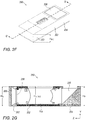
- FIG. 2F shows another embodiment of a folded camera disclosed herein and numbered 250, similar to folded camera 200.
- Camera 250 includes lens actuator 202 with lens actuator height H A 202 and carrying lens 204.
- Image sensor 208 is held in an image sensor holder 252.
- An OPFE 206 is held in a prism holder 254.
- an IR filter 256 is optionally positioned between lens 204 and image sensor 208.
- FIG. 2G shows a side cut of camera 250 along a line D'-D' seen in FIG. 2F .
- folded camera height H FC is limited by the maximum of H A 202 , H P and H S .
- a reduction H A 202 may lead to a reduction of H FC .
- a higher lens i.e. a lens with large H L
- the design of camera 250 has an advantage over the design of camera 150 by either having a lower camera height for the same optics, or by having better optics for the same camera height.
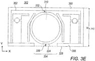
- FIGS. 3A-3E provide various views of a second embodiment of a lens actuator numbered 302, in which the lens actuator envelope 314 has a bottom opening 304 in a bottom lid 306.
- Lens actuator 302 is similar to lens actuator 202 and can be installed in a folded camera such as folded camera 200 in a similar manner.
- FIG. 3A shows lens actuator 302 actuating lens 310 in a top perspective view
- FIG. 3B shows lens actuator 302 without an upper envelope section from a top perspective view
- FIG. 3C shows lens actuator 302 from a bottom perspective view.
- FIG. 3D shows lens actuator 302 without an upper envelope section from a bottom perspective view
- FIG. 3E shows lens actuator 302 in a section view between sections E-E and F-F in FIG. 3A .
- Bottom opening 304 allows for a lower height penalty (air-gap) 336 and equal to the air-gap between a bottom surface 324 of the lens and an external bottom surface 328 of a bottom envelope section 306 measured along the first direction (Y axis). That is, lower height penalty 336 is smaller than lower height penalty 136 in FIGS. 1 .
- a second air gap 332 is positioned on the diametrically opposed side of lens 310 relative to air gap 336.
- An air gap 232 is between lens 310 and the internal surface 362 of upper envelope section 360, and allows the motion of lens 310 relative to upper envelope section 360.
- H A 302 is equal to H L plus the size of the two air-gaps 332 and 336, plus the thickness of upper envelope section 360.
- the height of each of air-gaps 332 and 336 can be 50-150 ⁇ m
- the thickness of upper envelope section 360 can be 100-150 ⁇ m
- H A 302 can be equal to the lens height H L plus 250 ⁇ m-500 ⁇ m. All other dimensions being equal, a lens actuator height H A 302 of camera 300 will be smaller than lens actuator height H A 102 in camera 100.
- lens actuator 302 may be combined in a folded camera between an OPFE and an image sensor, such that the height of the folded camera H FC may be equal to the height of the lens actuator H A 302.
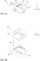
- FIGS. 4A-4C provide various views of a third embodiment of a folded lens actuator numbered 402 actuating a lens 410, in which a lens actuator envelope 414 has both a bottom opening and a top opening.
- FIG. 4A shows lens actuator 402 in a top perspective view
- FIG. 4B shows lens actuator 402 with a separated upper envelope section 416 from a bottom perspective view
- FIG. 4C shows lens actuator 402 in a section view between sections G-G and H-H in FIG. 4A .
- Arrow 460 shows the direction from which upper envelope section 216 is installed.
- Lens actuator 402 includes upper envelope section 416 with an opening 403 like opening 203 in lens actuator 202 and a bottom envelope section 406 with an opening 404 like opening 304 in lens actuator 302.
- lens actuator 402 combines the advantages provided by top opening 203 of lens actuator 202 and bottom opening 304 of lens actuator 302, with a final lens actuator height H A 402 smaller than the lens actuator heights in actuators 102, 202 and 302.
- lens actuator height H A 402 is equal to the lens height plus the size of two air-gaps 418 and 432.
- the size of each of the air-gaps 418 and 432 can be 50-150 ⁇ m and lens actuator height H A 402 can be equal to H L plus 100 ⁇ m or 250 ⁇ m or 300 ⁇ m.
- lens actuator 402 may be combined in a folded camera between an OPFE and an image sensor, such that the height of the folded camera H FC may be equal to the height of the lens actuator H A , 402.
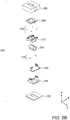
- FIGS. 5A , 5B , 6, 7 , 8 and 9 show one exemplary lens actuator design using VCM actuation. Such a design may be used in conjunction with envelope designs of lens actuators 202, 302 and 402.
- FIG. 5A and FIG. 5B show, respectively, exploded bottom and top perspective views of a VCM 502.
- VCM 502 comprises an envelope 506, an OIS/AF plate sub-assembly 508, four upper balls 510, a lens carrier sub-assembly 512, lens 514, four lower balls 516, an electronic sub-assembly 530, a base sub-assembly 540 and a lower plate 522.
- VCM 502 is capable of actuating any of the lenses above in two orthogonal directions, for example for focusing and optical image stabilization.
- FIG. 6 shows an exploded view of electronic sub-assembly 530.
- Electronic sub-assembly 530 comprises an OIS Hall bar sensor 602, an OIS coil 604, an AF Hall bar sensor 606, a first rigid printed board circuit (PCB) 608, a second rigid PCB 610 and a flex PCB 612.
- the control of the motion of any of the lenses above or below can be done in close loop mode using the position sensing allowed by Hall bar sensors 602 and 606.
- FIG. 7 shows an exploded view of base sub-assembly 540.
- Base sub-assembly 540 comprises an AF VCM 704, an AF stepping yoke 702 and a base 706.
- FIG. 8 shows an exploded view of lens carrier sub-assembly 512.
- Lens carrier sub-assembly 512 comprises an OIS VCM magnet 804, an OIS sensing magnet 802 and a lens carrier 806.
- FIG. 9 shows an exploded view of OIS/AF plate sub-assembly 508.
- OIS/AF plate sub-assembly 408 comprises an AF motor magnet 902, an OIS stepping yoke 904 and an OIS/AF plate 906.
- FIGS. 10-14 show another exemplary lens actuator design using VCM actuation.
- FIG. 10A shows an exploded view of a lens actuator 1004 using VCM actuation according to some aspects of presently disclosed subject matter
- lens actuator 1004 comprises an envelope 1014 serving as protection for the lens and other mechanical parts, a lens 1016 with a lens optical axis 1012, a lens carrier (holder) 1018, a plurality (e.g. four) of stepping magnets 1020a, b, c and d, an OIS magnet 1022, four upper balls 1024, an AF magnet 1026, a middle chassis 1028, four lower balls 1030, a base 1032, a plurality (e.g.
- stepping yokes 1034a, b, c and d four) of upper stepping yokes 1034a, b, c and d, an AF Hall sensor bar 1036, an AF coil 1038, an OIS coil 1040, a PCB 1042 serving as platform for placement of electrical components and electrical linkage between these electrical components, and OIS Hall sensor bar 1044 and a lower plate 1048 serving as bottom mechanical protection for the camera.
- some of the stepping yokes may positioned on a first surface, and other stepping yokes may be positioned on a second surface, wherein the first and second surfaces are parallel.
- FIGS. 10B and 10C show the positioning of AF coil 1038 and OIS coil 1040 relative to the lens optical axis 1012 from two different views.
- Each coil has a stadium shape, such that it has two long dimensions (typically 1-5mm long) and one short dimension (typically 0.1-0.5mm thick).
- Each coil typically has a few tens of windings (for example, in a non-limiting range of 50-250), with an exemplary resistance of 10-30 ohm.
- the plane in which the long dimensions of the coil reside will be considered henceforth to be the respective "coil plane".
- an "OIS coil plane" of OIS coil 1040 is parallel to the XZ plane, namely its two long dimensions are in XZ plane while its short dimension is along the Y axis.
- an "AF coil plane” of AF coil 1038 is parallel to the YZ plane, namely its two long dimensions are in the YZ plane while its short dimension is along the X axis.
- the OIS coil plane is perpendicular to the AF coil plane.
- OIS coil 1040 faces OIS magnet 1022 ( FIG. 10A ).
- the OIS magnet is a fixed (i.e. permenant) magnet.
- Magnet 1022 may be fabricated (e.g.
- OIS magnet 1022 has a magnetic field facing the negative Y direction, while on its negative X side, OIS magnet 1022 has a magnetic field facing the positive Y direction.
- a Lorenz force is created by the magnetic filed of OIS magnet 1022 on OIS coil 1040 in the negative or positive Y direction. Consequently, an equal force is applied on OIS magnet 1022 in the Y direction.
- OIS coil 1040 in XZ plane has the advantage in that, while in actuation, OIS magnet is kept at a constant distance from OIS coil 1022. That is, Lorentz force for OIS is uniform for different AF positions, and the OIS position reading is linear for OIS motion and uniform for different AF positions.
- lens optical axis 1012 is in the Z direction.
- Each of the OIS and AF planes is parallel to lens optical axis 1012.
- the OIS coil and the AF coil are on opposite sides of this plane. This feature has an advantage in that it reduces magnetic interference of the two VCMs.
- AF coil 1038 faces AF magnet 1026.
- the AF magnet is a fixed (i.e. permenant) magnet.
- AF magnet 1026 may be fabricated (e.g. sintered, cut) such that it has a changing magnetic field polarity: on its positive Z size, AF magnet 1026 has a magnetic field facing the negative X direction, while on its negative Z side OIS magnet 1022 has a magnetic field facing the positive X direction.
- a Lorenz force is created by the magnetic filed of AF magnet 1026 on AF coil 1038 in the negative or positive Z direction. Consequently, an equal force is applied on AF magnet 1026 in the Z direction.
- AF coil 1038 in YZ plane has the advantage in that, while in actuation, the AF magnet is kept at a constant distance from OIS coil 1040. That is, the Lorentz force for AF is uniform for different OIS positions, and the AF position reading is linear for AF motion and uniform for different OIS positions.
- FIG. 10D shows an envelope 1014' which is similar to envelope 1014 in VCM 1004, with an added top opening 1062.
- FIG. 10E shows a lower plate 1048' similar to lower plate 1048 in VCM 1004, with an added bottom opening 1064. Openings 1062 and 1064 allow reducing the height of VCM 1004, in a manner similar to openings 203 and 304 described above. All descriptions of embodiments 202, 302, 402, with regard to benefits of top and bottom openings are applicable to the description of VCM 1004 and may be used in VCM 1004.
- FIGS. 11A and 11B show exploded views from two perspectives of a first VCM actuator numbered 1100 included in lens actuator 1004.
- VCM actuator 1100 may be used for AF.
- VCM actuator 1100 may be used for OIS.
- a top actuating sub-assembly 1110 is movable relative to an AF stationary sub-assembly 1120 in a direction parallel to oprtical axis 1012.
- Top actuating sub-assembly 1110 comprises lens 1016, lens holder 1018, middle chasis 1028, AF magnet 1026 and the four stepping magnets 1020a, b, c and d, OIS magnet 1022, and four upper balls 1024.
- Middle chassis 1028 and AF magnet 1026 form a middle actuating sub-assembly 1130.
- AF stationary sub-assembly 1120 comprises a lower stepping yoke 1050, OIS Hall sensor bar 1044, printed circuit board 1042, OIS coil 1040, AF coil 1038, AF Hall sensor bar 1036, four upper stepping yokes 1034a, b, c and d and base 1032 (only some of which are seen in these figures).
- Middle actuating sub-assembly 1130 is movable relative to an AF stationary sub-assembly 1120 in a direction parallel to optical axis 1012 and movable relative to lens actuating sub-assembly 1210 in a direction perpendicular to optical axis 1012.
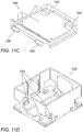
- FIGS. 11C and 11D show respectively four rails 1052 in middle chassis 1028 and four rails 1054 in base 1032. While one of rails 1054 is hidden in FIG. 11D , it is understood by a person skilled in the art that its location is symmetric with other visible rails.
- each of the four rails 1052 faces one respective rail of rails 1054, while one ball of lower balls 1030 is between the rails.
- the rails and ball structure confines the motion of top actuating sub-assembly 1110 relative to AF stationary sub-assembly 1120 in a direction parallel to optical axis 1012.
- top actuating sub-assembly 1110 is pulled to AF stationary sub-assembly 1120 in the Y direction due to the magnetic force of magnets 1020 and upper stepping yokes 1034 (see below), while balls 1030 keep the distance between top actuating sub-assembly 1110 and AF stationary sub-assembly 1120 constant in the Y direction.
- the term "constant distance” with respect to moving parts refers to a distance between the parts in a direction perpendicular to the motion direction that is constant with a tolerance of ⁇ 10 ⁇ m, ⁇ 30 ⁇ m, ⁇ 50 ⁇ m, or even ⁇ 100 ⁇ m.
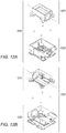
- FIGS. 12A and 12B show exploded top and bottom perspective views of a second VCM actuator in lens sub-assembly 1004, numbered 1200.
- VCM actuator 1200 includes a lens actuating sub-assembly 1210 movable relative to an OIS stationary sub-assembly 1220.
- VCM actuator 1200 may be used for OIS.
- Lens actuating sub-assembly 1210 comprises lens 1016, lens holder 1018, four stepping magnets 1020 and OIS magnet 1022 (which is also part of top actuating sub-assembly 1110 ).
- OIS stationary sub-assembly 1220 comprises lens holder 1018, middle chasis 1028, AF magnet 1026, AF stationary sub-assembly 1120 and the four lower balls 1030.
- FIGS. 12C and 12D show respectively four rails 1056 in lens carrier 1018 and four rails 1058 in middle chassis 1028.
- VCM actuator 1200 each of the four rails 1056 faces one respective rail of rails 1058, while one ball of upper balls 1024 is between the rails.
- the rails and ball structure confine the motion of lens actuating sub-assembly 1210 relative to OIS stationary actuating sub-assembly 1220 in a direction perpendicular to optical axis 1012.
- lens actuating sub-assembly 1210 is pulled to OIS stationary sub-assembly 1220 in the Y direction due to the magnetic force of magnets 1020 a,b,c and d and stepping yokes 1034a,b,c and d (see beolw), while upper balls 1024 keep the distance between lens actuating sub-assembly 1210 and OIS stationary sub-assembly 1220 constant in the Y direction.
- the lens actuating sub-assembly is pulled toward the stationary sub-assembly, with the middle actuating sub-assembley positioned therebetween.
- an electrical current in AF coil 1038 creates force on AF magnet 1026, driving middle chassis 1028 in directions parallel to lens optical axis 1012, for example along the positive or negative Z direction.
- Middle chassis 1028 holds lens actuating sub-assembly 1210 and while moving in the AF direction it carries lens actuating sub-assembly 1210 along, such that lens 1016 is operative to focus on image sensor 1006, as required by optical demands.
- the AF movement is directed by the rolling and/or sliding of the four lower balls 1030 inside the four respective rails 1052 located in middle chassis 1028 and inside four compatible rails 1054 located in base 1032.
- actuator 1200 for OIS In use of actuator 1200 for OIS, electrical current in OIS coil 1040 creates force on OIS magnet 1022, driving lens carrier 1018 in directions perpendicular to the lens optical axis 1012 and parallel to the X axis (shown in the examplary coordinate system XYZ). During this movement, lens carrier 1018 (which holds lens 1016 ) moves together with the lens in any OIS direction.
- the movement for OIS is directed by the rolling and/or sliding of four upper balls 1024 inside four rails 1056 located on lens carrier 1018 and inside another four compatible rails 1058 located on the middle chassis 1028.
- the four stepping magnets 1020a, 1020b, 1020c and 1020d located on the lens carrier 1018 are assocated with four stepping yokes 1034a, 1034b, 1034c and 1034d located on AF stationary sub-assembly 1120, creating a stepping force indicated by arrows in a direction perpendicular to optical axis 1012.
- Stepping magnets 1020a-d and stepping yokes 1034a-d are seen in FIG. 13A , which shows an exploded view of VCM 1100, and in FIG. 13B which shows only the magnets and yokes along with the force direction, which is directed in the negative Y direction.
- lens actuating sub-assembly 1210 is pulled toward AF stationary sub-assembly 1120, while OIS stationary sub-assembly 1220 is positioned therebetween.
- Upper balls 1024 located between lens actuating sub-assembly 1210 and OIS stationary sub-assembly 1220 prevent contact between the two sub-assemblies.
- lower balls 1030 located between OIS stationary sub-assembly 1220 and AF stationary sub-assembly 1120 prevent contact between the two sub-assemblies.
- the pull force created between four stepping magnets 1020 and four stepping yokes 1034 hold actuator 1100 as one unit and prevent all moving parts from coming apart.
- the three stepping magnets are used only for stepping, while the fourth magnet is used for stepping and sensing.
- FIGS. 14A and 14B show top actuating sub-assembly 1110 in, respectively, an exploded perspective view and an assembled view.
- lens carrier 1018 has an an opening 1402 which allows light to pass from an OPFE to lens 1016. Opening 1 402 is surrounded by walls 1404 a, b, c and d.
- middle chassis 1028 comprises walls 1 406 a, b, c and d.
- Wall 1406b can be used to add mechanical strength and connect between the rails.
- FIGS. 14C and 14D show two different embodiments in cross section along the optical axis of top actuating sub-assembly 1110 and a prism 1410. The embodiments shown in FIGS. 14C and 14D describe two relative positions of walls 1406b and 1404b. In the embodiment of FIG. 14C , wall 1406b is located below wall 1404b (in the -Y direction).
- a distance 1408 denotes the minimal distance of top actuating sub-assembly 1110 from prism 1410.
- Distance 1408 is determined by a stroke for AF of top actuating sub-assembly 1110, as required by optical needs and assembly togruces, as required by mechanical needs.
- Distance 1408 is constant in both configurations ( FIGS. 14C and 14D ).
- the configuration in FIG. 14C has an advantage, since it allows a shorter actuator along the optical axis direction (-Z direction), namely a reduction in the length of folded camera 1000 ( FIG. 10A ).
- FIG. 15 shows a dual camera 1500 comprising an upright camera 1502 and a folded camera 1504 .
- Folded camera 1504 may include a lens actuator like any actuator/VCM disclosed above, for example actuators/VCMs 102, 202, 302, 402, 502 or 1004.
Applications Claiming Priority (6)
| Application Number | Priority Date | Filing Date | Title |
|---|---|---|---|
| US201862626306P | 2018-02-05 | 2018-02-05 | |
| US201862658819P | 2018-04-17 | 2018-04-17 | |
| US201862672754P | 2018-05-17 | 2018-05-17 | |
| US201862677012P | 2018-05-27 | 2018-05-27 | |
| PCT/IB2018/060203 WO2019150188A1 (fr) | 2018-02-05 | 2018-12-17 | Pénalité de hauteur réduite pour appareil photo plié |
| EP18897859.7A EP3552050B1 (fr) | 2018-02-05 | 2018-12-17 | Pénalité de hauteur réduite pour appareil photo plié |
Related Parent Applications (2)
| Application Number | Title | Priority Date | Filing Date |
|---|---|---|---|
| EP18897859.7A Division-Into EP3552050B1 (fr) | 2018-02-05 | 2018-12-17 | Pénalité de hauteur réduite pour appareil photo plié |
| EP18897859.7A Division EP3552050B1 (fr) | 2018-02-05 | 2018-12-17 | Pénalité de hauteur réduite pour appareil photo plié |
Publications (1)
| Publication Number | Publication Date |
|---|---|
| EP3848749A1 true EP3848749A1 (fr) | 2021-07-14 |
Family
ID=67478638
Family Applications (2)
| Application Number | Title | Priority Date | Filing Date |
|---|---|---|---|
| EP21159192.0A Pending EP3848749A1 (fr) | 2018-02-05 | 2018-12-17 | Pénalité de hauteur réduite pour appareil photo plié |
| EP18897859.7A Active EP3552050B1 (fr) | 2018-02-05 | 2018-12-17 | Pénalité de hauteur réduite pour appareil photo plié |
Family Applications After (1)
| Application Number | Title | Priority Date | Filing Date |
|---|---|---|---|
| EP18897859.7A Active EP3552050B1 (fr) | 2018-02-05 | 2018-12-17 | Pénalité de hauteur réduite pour appareil photo plié |
Country Status (5)
| Country | Link |
|---|---|
| US (3) | US10976567B2 (fr) |
| EP (2) | EP3848749A1 (fr) |
| KR (3) | KR102128223B1 (fr) |
| CN (2) | CN110352371B (fr) |
| WO (1) | WO2019150188A1 (fr) |
Families Citing this family (8)
| Publication number | Priority date | Publication date | Assignee | Title |
|---|---|---|---|---|
| US11243455B2 (en) * | 2019-09-25 | 2022-02-08 | Apple Inc. | Camera with folded optics |
| TWI730637B (zh) * | 2020-02-24 | 2021-06-11 | 大陽科技股份有限公司 | 相機模組與電子裝置 |
| CN114424104B (zh) * | 2020-08-12 | 2023-06-30 | 核心光电有限公司 | 扫描折叠相机中的光学防抖 |
| CN114167570B (zh) * | 2020-09-10 | 2023-06-06 | 华为技术有限公司 | 光学镜头、摄像模组、电子设备及摄像模组的拍摄方法 |
| KR102592576B1 (ko) * | 2020-11-05 | 2023-10-20 | 코어포토닉스 리미티드 | 2개의 광학 경로 폴딩 요소 시야 스캐닝에 기초한 스캐닝 텔레 카메라 |
| KR102460759B1 (ko) * | 2021-01-27 | 2022-10-31 | 삼성전기주식회사 | 폴디드 줌 ois 회로 및 카메라 장치 |
| CN115086507B (zh) * | 2021-03-10 | 2023-08-22 | 宁波舜宇光电信息有限公司 | 可伸缩式摄像模组和电子设备 |
| TWI793978B (zh) * | 2021-12-02 | 2023-02-21 | 大陽科技股份有限公司 | 攝影模組與電子裝置 |
Citations (5)
| Publication number | Priority date | Publication date | Assignee | Title |
|---|---|---|---|---|
| US20110121666A1 (en) * | 2009-11-20 | 2011-05-26 | Lg Innotek Co., Ltd. | Voice Coil Motor |
| US20110235196A1 (en) | 2010-03-26 | 2011-09-29 | Hon Hai Precision Industry Co., Ltd. | Voice coil motor and camera module with same |
| US8810714B2 (en) | 2007-07-18 | 2014-08-19 | Samsung Electronics Co., Ltd. | Camera system with auto-focus function and control method thereof |
| WO2016207754A1 (fr) * | 2015-06-24 | 2016-12-29 | Corephotonics Ltd. | Actionneur tri-axe à profil bas pour caméra à objectif coudé |
| US20180017844A1 (en) * | 2016-07-12 | 2018-01-18 | Tdk Taiwan Corp. | Lens driving module |
Family Cites Families (316)
| Publication number | Priority date | Publication date | Assignee | Title |
|---|---|---|---|---|
| US4199785A (en) | 1979-01-05 | 1980-04-22 | Honeywell Inc. | Electronic zoom system |
| JPS59191146A (ja) | 1983-04-13 | 1984-10-30 | Hitachi Ltd | 光学走査装置 |
| US5099263A (en) | 1984-11-10 | 1992-03-24 | Minolta Camera Kabushiki Kaisha | Variable focal length camera |
| EP0342419B1 (fr) | 1988-05-19 | 1992-10-28 | Siemens Aktiengesellschaft | Méthode pour l'observation d'une scène et dispositif associé |
| DE3927334C1 (fr) | 1989-08-18 | 1991-01-10 | Messerschmitt-Boelkow-Blohm Gmbh, 8012 Ottobrunn, De | |
| JP2703105B2 (ja) | 1989-10-20 | 1998-01-26 | 富士写真フイルム株式会社 | 手振れ補正装置 |
| US5032917A (en) | 1990-03-12 | 1991-07-16 | Rca Licensing Corporation | Video signal blending apparatus |
| JPH0443773A (ja) | 1990-06-11 | 1992-02-13 | Matsushita Electric Ind Co Ltd | 演算回路 |
| US5041852A (en) | 1990-10-18 | 1991-08-20 | Fjui Photo Film Co., Ltd. | Camera shake correction system |
| JP3261152B2 (ja) | 1991-03-13 | 2002-02-25 | シャープ株式会社 | 複数の光学系を備えた撮像装置 |
| US5394520A (en) | 1991-09-26 | 1995-02-28 | Hughes Aircraft Company | Imaging apparatus for providing a composite digital representation of a scene within a field of regard |
| US5657402A (en) | 1991-11-01 | 1997-08-12 | Massachusetts Institute Of Technology | Method of creating a high resolution still image using a plurality of images and apparatus for practice of the method |
| US5248971A (en) | 1992-05-19 | 1993-09-28 | Mandl William J | Method and apparatus for multiplexed oversampled analog to digital modulation |
| JPH06177706A (ja) | 1992-12-08 | 1994-06-24 | Sony Corp | 信号処理装置 |
| DE69324224T2 (de) | 1992-12-29 | 1999-10-28 | Koninkl Philips Electronics Nv | Bildverarbeitungsverfahren und -vorrichtung zum Erzeugen eines Bildes aus mehreren angrenzenden Bildern |
| US5682198A (en) | 1993-06-28 | 1997-10-28 | Canon Kabushiki Kaisha | Double eye image pickup apparatus |
| US6128416A (en) | 1993-09-10 | 2000-10-03 | Olympus Optical Co., Ltd. | Image composing technique for optimally composing a single image from a plurality of digital images |
| JP3355787B2 (ja) | 1994-05-20 | 2002-12-09 | ソニー株式会社 | 光軸補正機構 |
| US6714665B1 (en) | 1994-09-02 | 2004-03-30 | Sarnoff Corporation | Fully automated iris recognition system utilizing wide and narrow fields of view |
| CA2155719C (fr) | 1994-11-22 | 2005-11-01 | Terry Laurence Glatt | Systeme de surveillance video avec cameras pilotes et asservies |
| JPH08271976A (ja) | 1995-03-29 | 1996-10-18 | Canon Inc | カメラ |
| US5768443A (en) | 1995-12-19 | 1998-06-16 | Cognex Corporation | Method for coordinating multiple fields of view in multi-camera |
| US5982951A (en) | 1996-05-28 | 1999-11-09 | Canon Kabushiki Kaisha | Apparatus and method for combining a plurality of images |
| US5926190A (en) | 1996-08-21 | 1999-07-20 | Apple Computer, Inc. | Method and system for simulating motion in a computer graphics application using image registration and view interpolation |
| JPH10126796A (ja) | 1996-09-12 | 1998-05-15 | Eastman Kodak Co | デュアル・モード・ソフトウェア処理を用いた動画・静止画像用デジタル・カメラ |
| US5960218A (en) | 1997-02-18 | 1999-09-28 | Mobi Corporation | Dual focal length camera |
| US5940641A (en) | 1997-07-10 | 1999-08-17 | Eastman Kodak Company | Extending panoramic images |
| US6148120A (en) | 1997-10-30 | 2000-11-14 | Cognex Corporation | Warping of focal images to correct correspondence error |
| US6268611B1 (en) | 1997-12-18 | 2001-07-31 | Cellavision Ab | Feature-free registration of dissimilar images using a robust similarity metric |
| JP3695119B2 (ja) | 1998-03-05 | 2005-09-14 | 株式会社日立製作所 | 画像合成装置、及び画像合成方法を実現するプログラムを記録した記録媒体 |
| US6208765B1 (en) | 1998-06-19 | 2001-03-27 | Sarnoff Corporation | Method and apparatus for improving image resolution |
| GB9823689D0 (en) | 1998-10-30 | 1998-12-23 | Greenagate Limited | Improved methods and apparatus for 3-D imaging |
| US6611289B1 (en) | 1999-01-15 | 2003-08-26 | Yanbin Yu | Digital cameras using multiple sensors with multiple lenses |
| US6738073B2 (en) | 1999-05-12 | 2004-05-18 | Imove, Inc. | Camera system with both a wide angle view and a high resolution view |
| US20020063711A1 (en) | 1999-05-12 | 2002-05-30 | Imove Inc. | Camera system with high resolution image inside a wide angle view |
| US20020075258A1 (en) | 1999-05-12 | 2002-06-20 | Imove Inc. | Camera system with high resolution image inside a wide angle view |
| US6346950B1 (en) | 1999-05-20 | 2002-02-12 | Compaq Computer Corporation | System and method for display images using anamorphic video |
| US7038716B2 (en) | 1999-07-30 | 2006-05-02 | Pixim, Inc. | Mobile device equipped with digital image sensor |
| US7015954B1 (en) | 1999-08-09 | 2006-03-21 | Fuji Xerox Co., Ltd. | Automatic video system using multiple cameras |
| US6650368B1 (en) | 1999-10-26 | 2003-11-18 | Hewlett-Packard Development Company, Lp. | Digital camera and method of enhancing zoom effects |
| US6643416B1 (en) | 1999-11-30 | 2003-11-04 | Eastman Kodak Company | Method for determining necessary resolution for zoom and crop images |
| US20020005902A1 (en) | 2000-06-02 | 2002-01-17 | Yuen Henry C. | Automatic video recording system using wide-and narrow-field cameras |
| JP2002010276A (ja) | 2000-06-22 | 2002-01-11 | Olympus Optical Co Ltd | 撮像装置 |
| JP4501239B2 (ja) | 2000-07-13 | 2010-07-14 | ソニー株式会社 | カメラ・キャリブレーション装置及び方法、並びに、記憶媒体 |
| US7002583B2 (en) | 2000-08-03 | 2006-02-21 | Stono Technologies, Llc | Display of images and image transitions |
| US6778207B1 (en) | 2000-08-07 | 2004-08-17 | Koninklijke Philips Electronics N.V. | Fast digital pan tilt zoom video |
| US7345277B2 (en) | 2000-08-09 | 2008-03-18 | Evan Zhang | Image intensifier and LWIR fusion/combination system |
| JP2002214662A (ja) | 2001-01-23 | 2002-07-31 | Olympus Optical Co Ltd | 光学装置の振れ補正装置 |
| US6741250B1 (en) | 2001-02-09 | 2004-05-25 | Be Here Corporation | Method and system for generation of multiple viewpoints into a scene viewed by motionless cameras and for presentation of a view path |
| US7346217B1 (en) | 2001-04-25 | 2008-03-18 | Lockheed Martin Corporation | Digital image enhancement using successive zoom images |
| JP2002341220A (ja) * | 2001-05-14 | 2002-11-27 | Olympus Optical Co Ltd | 光学機器 |
| GB0116877D0 (en) | 2001-07-10 | 2001-09-05 | Hewlett Packard Co | Intelligent feature selection and pan zoom control |
| US6680748B1 (en) | 2001-09-27 | 2004-01-20 | Pixim, Inc., | Multi-mode camera and method therefor |
| US20030093805A1 (en) | 2001-11-15 | 2003-05-15 | Gin J.M. Jack | Dual camera surveillance and control system |
| US7339621B2 (en) | 2001-12-13 | 2008-03-04 | Psion Teklogix Systems, Inc. | Imager output signal processing |
| JP4198449B2 (ja) | 2002-02-22 | 2008-12-17 | 富士フイルム株式会社 | デジタルカメラ |
| JP2003298920A (ja) | 2002-03-29 | 2003-10-17 | Fuji Photo Film Co Ltd | デジタルカメラ |
| JP4657564B2 (ja) | 2002-04-30 | 2011-03-23 | イーストマン コダック カンパニー | 電子スチルカメラ及び画像処理方法 |
| GB2388265B (en) | 2002-04-30 | 2005-10-12 | Hewlett Packard Co | Improvements in and relating to processing of images |
| CA2386560A1 (fr) | 2002-05-15 | 2003-11-15 | Idelix Software Inc. | Commande de materiel optique et de systemes d'affichage de donnees dynamiques au moyen d'outils d'affichage de details en contexte |
| JP3870124B2 (ja) | 2002-06-14 | 2007-01-17 | キヤノン株式会社 | 画像処理装置及びその方法、並びにコンピュータプログラム及びコンピュータ可読記憶媒体 |
| US6839067B2 (en) | 2002-07-26 | 2005-01-04 | Fuji Xerox Co., Ltd. | Capturing and producing shared multi-resolution video |
| US20040061788A1 (en) | 2002-09-26 | 2004-04-01 | Logitech Europe S.A. | Multiple mode capture button for a digital camera |
| JP4481560B2 (ja) | 2002-10-08 | 2010-06-16 | オリンパス株式会社 | レンズ鏡筒 |
| US7321470B2 (en) | 2002-10-08 | 2008-01-22 | Olympus Corporation | Camera |
| GB2394852B (en) | 2002-10-31 | 2006-12-20 | Hewlett Packard Co | Image capture systems using motion detection |
| JP2004219569A (ja) | 2003-01-10 | 2004-08-05 | Olympus Corp | 電子撮像装置 |
| JP3861815B2 (ja) | 2003-01-17 | 2006-12-27 | コニカミノルタフォトイメージング株式会社 | 手振れ補正機能付きカメラ |
| JP4055599B2 (ja) | 2003-02-13 | 2008-03-05 | コニカミノルタオプト株式会社 | 撮像レンズ装置およびそれを備えた電子機器 |
| AU2003236050A1 (en) | 2003-03-20 | 2004-10-11 | Seijiro Tomita | Panoramic picture creating method and device, and monitor system using the method and device |
| CN1574894A (zh) | 2003-06-02 | 2005-02-02 | 宾得株式会社 | 多焦距成像装置和具有该多焦距成像装置的移动装置 |
| US7596284B2 (en) | 2003-07-16 | 2009-09-29 | Hewlett-Packard Development Company, L.P. | High resolution image reconstruction |
| US7619683B2 (en) | 2003-08-29 | 2009-11-17 | Aptina Imaging Corporation | Apparatus including a dual camera module and method of using the same |
| JP2005099265A (ja) | 2003-09-24 | 2005-04-14 | Fujinon Corp | 撮像装置および撮像方法、ならびに測距方法 |
| EP1536633A1 (fr) | 2003-11-27 | 2005-06-01 | Sony Corporation | Appareil photographique et méthode, système de supervision, programme et medium d'enregistrement |
| JP2005208194A (ja) | 2004-01-21 | 2005-08-04 | Konica Minolta Photo Imaging Inc | 撮影装置 |
| KR20050090780A (ko) | 2004-03-10 | 2005-09-14 | 삼성전자주식회사 | 영상촬영장치 |
| JP2008507229A (ja) | 2004-07-19 | 2008-03-06 | グランドアイ,エルティーディー | 広角ビデオカメラのズーム機能の自動拡張 |
| WO2006008805A1 (fr) | 2004-07-20 | 2006-01-26 | Five Dimension Co., Ltd. | Dispositif électronique d’imagerie |
| US7916180B2 (en) | 2004-08-25 | 2011-03-29 | Protarius Filo Ag, L.L.C. | Simultaneous multiple field of view digital cameras |
| US7564019B2 (en) | 2005-08-25 | 2009-07-21 | Richard Ian Olsen | Large dynamic range cameras |
| EP1812968B1 (fr) | 2004-08-25 | 2019-01-16 | Callahan Cellular L.L.C. | Appareil pour plusieurs dispositifs photographiques et procédé de fonctionnement associé |
| US7465107B2 (en) | 2004-09-21 | 2008-12-16 | Canon Kabushiki Kaisha | Photographing apparatus and control method therefor |
| KR101054344B1 (ko) | 2004-11-17 | 2011-08-04 | 삼성전자주식회사 | 박막 트랜지스터 표시판 및 그 제조 방법 |
| US7688364B2 (en) | 2004-12-10 | 2010-03-30 | Ambarella, Inc. | Decimating and cropping based zoom factor for a digital camera |
| KR100636969B1 (ko) | 2004-12-30 | 2006-10-19 | 매그나칩 반도체 유한회사 | Isp 내장형 이미지 센서 및 듀얼 카메라 시스템 |
| US7573514B2 (en) | 2005-02-03 | 2009-08-11 | Eastman Kodak Company | Digital imaging system with digital zoom warning |
| US7663662B2 (en) | 2005-02-09 | 2010-02-16 | Flir Systems, Inc. | High and low resolution camera systems and methods |
| US7236306B2 (en) | 2005-02-18 | 2007-06-26 | Eastman Kodak Company | Digital camera using an express zooming mode to provide expedited operation over an extended zoom range |
| US20060187322A1 (en) | 2005-02-18 | 2006-08-24 | Janson Wilbert F Jr | Digital camera using multiple fixed focal length lenses and multiple image sensors to provide an extended zoom range |
| US7206136B2 (en) | 2005-02-18 | 2007-04-17 | Eastman Kodak Company | Digital camera using multiple lenses and image sensors to provide an extended zoom range |
| US7256944B2 (en) | 2005-02-18 | 2007-08-14 | Eastman Kodak Company | Compact image capture assembly using multiple lenses and image sensors to provide an extended zoom range |
| US7561191B2 (en) | 2005-02-18 | 2009-07-14 | Eastman Kodak Company | Camera phone using multiple lenses and image sensors to provide an extended zoom range |
| JP2006238325A (ja) | 2005-02-28 | 2006-09-07 | Canon Inc | カメラシステム |
| KR100658150B1 (ko) | 2005-04-08 | 2006-12-15 | 삼성전기주식회사 | 카메라 모듈 및 이의 제작방법 |
| JP3934151B2 (ja) | 2005-06-22 | 2007-06-20 | 松下電器産業株式会社 | 画像生成装置および画像生成方法 |
| KR20070005946A (ko) | 2005-07-05 | 2007-01-11 | 엘지전자 주식회사 | 휴대 단말기용 카메라 렌즈의 위치 검출 장치 |
| JP2007033879A (ja) | 2005-07-27 | 2007-02-08 | Sony Corp | 撮像レンズ装置及び撮像装置 |
| US7424218B2 (en) | 2005-07-28 | 2008-09-09 | Microsoft Corporation | Real-time preview for panoramic images |
| JP4573725B2 (ja) | 2005-08-01 | 2010-11-04 | イーストマン コダック カンパニー | 複数光学系を有する撮像装置 |
| JP4573724B2 (ja) | 2005-08-01 | 2010-11-04 | イーストマン コダック カンパニー | 複数光学系を有する撮像装置 |
| US7964835B2 (en) | 2005-08-25 | 2011-06-21 | Protarius Filo Ag, L.L.C. | Digital cameras with direct luminance and chrominance detection |
| CN101310218B (zh) | 2005-11-14 | 2011-07-13 | 株式会社尼康 | 图像模糊修正装置和相机 |
| JP4788953B2 (ja) | 2005-11-16 | 2011-10-05 | ソニー株式会社 | 撮像装置及びズームレンズ |
| US8238695B1 (en) | 2005-12-15 | 2012-08-07 | Grandeye, Ltd. | Data reduction techniques for processing wide-angle video |
| US20070177025A1 (en) | 2006-02-01 | 2007-08-02 | Micron Technology, Inc. | Method and apparatus minimizing die area and module size for a dual-camera mobile device |
| JP4579842B2 (ja) | 2006-02-06 | 2010-11-10 | イーストマン コダック カンパニー | 撮像装置 |
| EP1984774A4 (fr) | 2006-02-06 | 2010-11-24 | Nokia Corp | Stabilisateur d'image optique utilisant un prisme à cardan |
| CN101401022B (zh) | 2006-02-06 | 2010-07-21 | 诺基亚公司 | 在成像系统中进行位置检测的方法和设备 |
| US9182228B2 (en) | 2006-02-13 | 2015-11-10 | Sony Corporation | Multi-lens array system and method |
| JP2007212961A (ja) * | 2006-02-13 | 2007-08-23 | Matsushita Electric Ind Co Ltd | ズームレンズ系、撮像装置及びカメラ |
| JP4622882B2 (ja) | 2006-02-21 | 2011-02-02 | カシオ計算機株式会社 | デジタルカメラ |
| US7708478B2 (en) | 2006-04-13 | 2010-05-04 | Nokia Corporation | Actuator mechanism and a shutter mechanism |
| US7773121B1 (en) | 2006-05-03 | 2010-08-10 | The United States Of America As Represented By The Administrator Of The National Aeronautics And Space Administration | High-resolution, continuous field-of-view (FOV), non-rotating imaging system |
| JP2007306282A (ja) | 2006-05-11 | 2007-11-22 | Citizen Electronics Co Ltd | カメラモジュール |
| KR100749337B1 (ko) | 2006-06-13 | 2007-08-14 | 삼성전자주식회사 | 복수의 카메라렌즈를 구비한 이동통신단말기를 이용한 촬영방법 및 장치 |
| US7737379B2 (en) | 2006-07-19 | 2010-06-15 | Witdouck Calvin J | System and method for sorting larvae cocoons |
| US8189100B2 (en) | 2006-07-25 | 2012-05-29 | Qualcomm Incorporated | Mobile device with dual digital camera sensors and methods of using the same |
| US7756330B2 (en) | 2006-07-27 | 2010-07-13 | Eastman Kodak Company | Producing an extended dynamic range digital image |
| US20080030592A1 (en) | 2006-08-01 | 2008-02-07 | Eastman Kodak Company | Producing digital image with different resolution portions |
| US7667762B2 (en) | 2006-08-01 | 2010-02-23 | Lifesize Communications, Inc. | Dual sensor video camera |
| JP2008076485A (ja) | 2006-09-19 | 2008-04-03 | Konica Minolta Opto Inc | レンズ鏡胴、及び撮像装置 |
| JP2008096584A (ja) | 2006-10-10 | 2008-04-24 | Nikon Corp | カメラ |
| KR100856572B1 (ko) * | 2006-11-02 | 2008-09-04 | 주식회사 엠씨넥스 | 카메라 모듈 |
| US7697053B2 (en) | 2006-11-02 | 2010-04-13 | Eastman Kodak Company | Integrated display having multiple capture devices |
| JP4448844B2 (ja) | 2006-11-22 | 2010-04-14 | 富士フイルム株式会社 | 複眼撮像装置 |
| KR100871566B1 (ko) | 2006-12-04 | 2008-12-02 | 삼성전자주식회사 | 이미지 촬상 장치의 손떨림 보상을 위한 장치 및 방법 |
| US7533819B2 (en) | 2007-01-31 | 2009-05-19 | Symbol Technologies, Inc. | Dual camera assembly for an imaging-based bar code reader |
| US7978239B2 (en) | 2007-03-01 | 2011-07-12 | Eastman Kodak Company | Digital camera using multiple image sensors to provide improved temporal sampling |
| US7859588B2 (en) | 2007-03-09 | 2010-12-28 | Eastman Kodak Company | Method and apparatus for operating a dual lens camera to augment an image |
| US7729602B2 (en) | 2007-03-09 | 2010-06-01 | Eastman Kodak Company | Camera using multiple lenses and image sensors operable in a default imaging mode |
| US7676146B2 (en) | 2007-03-09 | 2010-03-09 | Eastman Kodak Company | Camera using multiple lenses and image sensors to provide improved focusing capability |
| US7683962B2 (en) | 2007-03-09 | 2010-03-23 | Eastman Kodak Company | Camera using multiple lenses and image sensors in a rangefinder configuration to provide a range map |
| WO2008129552A1 (fr) | 2007-04-19 | 2008-10-30 | Dvp Technologies Ltd. | Système et procédé de prise d'image destinés à la surveillance d'un champ de regard |
| US7918398B2 (en) | 2007-06-04 | 2011-04-05 | Hand Held Products, Inc. | Indicia reading terminal having multiple setting imaging lens |
| US8390729B2 (en) | 2007-09-05 | 2013-03-05 | International Business Machines Corporation | Method and apparatus for providing a video image having multiple focal lengths |
| US20090086074A1 (en) | 2007-09-27 | 2009-04-02 | Omnivision Technologies, Inc. | Dual mode camera solution apparatus, system, and method |
| JP2009109904A (ja) * | 2007-10-31 | 2009-05-21 | Sony Corp | レンズ鏡筒及び撮像装置 |
| US20090122195A1 (en) | 2007-11-09 | 2009-05-14 | Van Baar Jeroen | System and Method for Combining Image Sequences |
| US20090128644A1 (en) | 2007-11-15 | 2009-05-21 | Camp Jr William O | System and method for generating a photograph |
| KR20090058229A (ko) | 2007-12-04 | 2009-06-09 | 삼성전기주식회사 | 듀얼 카메라 모듈 |
| US8310587B2 (en) | 2007-12-04 | 2012-11-13 | DigitalOptics Corporation International | Compact camera optics |
| WO2009097552A1 (fr) | 2008-02-01 | 2009-08-06 | Omnivision Cdm Optics, Inc. | Systemes et procedes de fusion de donnees d’image |
| US8115825B2 (en) | 2008-02-20 | 2012-02-14 | Apple Inc. | Electronic device with two image sensors |
| CN101276415A (zh) | 2008-03-03 | 2008-10-01 | 北京航空航天大学 | 用多定焦摄像机实现多分辨率图像采集的装置和方法 |
| US20100097444A1 (en) | 2008-10-16 | 2010-04-22 | Peter Lablans | Camera System for Creating an Image From a Plurality of Images |
| US8866920B2 (en) | 2008-05-20 | 2014-10-21 | Pelican Imaging Corporation | Capturing and processing of images using monolithic camera array with heterogeneous imagers |
| FI20085510L (fi) | 2008-05-28 | 2009-11-29 | Valtion Teknillinen | Zoom-kamera -järjestely, joka käsittää useita alikameroita |
| JP4513906B2 (ja) | 2008-06-27 | 2010-07-28 | ソニー株式会社 | 画像処理装置、画像処理方法、プログラム及び記録媒体 |
| KR101477178B1 (ko) | 2008-07-17 | 2014-12-29 | 삼성전자주식회사 | 듀얼 카메라를 구비하는 휴대 단말기 및 이를 이용한 촬영방법 |
| US8134589B2 (en) | 2008-07-17 | 2012-03-13 | Eastman Kodak Company | Zoom by multiple image capture |
| GB2462095A (en) | 2008-07-23 | 2010-01-27 | Snell & Wilcox Ltd | Processing of images to represent a transition in viewpoint |
| US8237807B2 (en) | 2008-07-24 | 2012-08-07 | Apple Inc. | Image capturing device with touch screen for adjusting camera settings |
| JP5118751B2 (ja) | 2008-09-10 | 2013-01-16 | パナソニック株式会社 | カメラ本体および撮像装置 |
| CN101394487B (zh) | 2008-10-27 | 2011-09-14 | 华为技术有限公司 | 一种合成图像的方法与系统 |
| JP5230376B2 (ja) | 2008-11-28 | 2013-07-10 | 三星電子株式会社 | 撮像装置及び撮像方法 |
| JP5265336B2 (ja) | 2008-12-25 | 2013-08-14 | 富士フイルム株式会社 | 手振れ補正装置及び光学機器 |
| JP2010204341A (ja) | 2009-03-03 | 2010-09-16 | Nikon Corp | カメラ |
| CN101833157A (zh) | 2009-03-13 | 2010-09-15 | 鸿富锦精密工业(深圳)有限公司 | 相机模组 |
| CN105681633B (zh) | 2009-03-19 | 2019-01-18 | 数字光学公司 | 双传感器照相机及其方法 |
| WO2010116369A1 (fr) | 2009-04-07 | 2010-10-14 | Nextvision Stabilized Systems Ltd | Procédés de fabrication d'un système de caméra comprenant une pluralité de capteurs d'images |
| KR101552481B1 (ko) | 2009-04-13 | 2015-09-21 | 삼성전자 주식회사 | 줌 렌즈 모듈 |
| WO2010122841A1 (fr) * | 2009-04-22 | 2010-10-28 | コニカミノルタオプト株式会社 | Cylindre à miroirs-lentilles, dispositif de saisie d'image et procédé de fabrication de cylindre à miroirs-lentilles |
| US8553106B2 (en) | 2009-05-04 | 2013-10-08 | Digitaloptics Corporation | Dual lens digital zoom |
| BRPI0924538A2 (pt) | 2009-06-16 | 2015-08-11 | Intel Corp | Aplicações de câmera em um dispositivo portátil |
| WO2010148363A2 (fr) | 2009-06-18 | 2010-12-23 | Theia Technologies, Llc | Caméra à dôme compacte |
| WO2011005413A2 (fr) | 2009-06-22 | 2011-01-13 | Omnivision Technologies, Inc. | Système et procédé pour détecteur d'image actionnable dans des normes vidéo multiples |
| WO2011009108A2 (fr) | 2009-07-17 | 2011-01-20 | Universal Robotics, Inc. | Système et procédé de calibrage automatique dimages stéréo |
| JP5846346B2 (ja) | 2009-08-21 | 2016-01-20 | ミツミ電機株式会社 | カメラの手振れ補正装置 |
| CN201514511U (zh) | 2009-09-08 | 2010-06-23 | 华晶科技股份有限公司 | 潜望式镜头结构 |
| KR101613928B1 (ko) | 2009-09-09 | 2016-04-20 | 엘지전자 주식회사 | 이동 단말기 |
| WO2011029203A1 (fr) | 2009-09-14 | 2011-03-17 | Viion Systems Inc. | Caméra d'analyse vidéo à double résolution saccadée |
| KR101617289B1 (ko) | 2009-09-30 | 2016-05-02 | 엘지전자 주식회사 | 휴대 단말기 및 그 동작 제어방법 |
| JP5513834B2 (ja) | 2009-10-13 | 2014-06-04 | 台湾東電化股▲ふん▼有限公司 | レンズ駆動装置 |
| CA3043204C (fr) | 2009-11-19 | 2021-08-31 | Esight Corp. | Appareil et methode destines a une " region d'interet " dynamique dans un systeme d'affichage |
| WO2011063347A2 (fr) | 2009-11-20 | 2011-05-26 | Pelican Imaging Corporation | Capture et traitement d'images au moyen d'un réseau de caméras monolithique équipé d'imageurs hétérogènes |
| US8400555B1 (en) | 2009-12-01 | 2013-03-19 | Adobe Systems Incorporated | Focused plenoptic camera employing microlenses with different focal lengths |
| US20110128288A1 (en) | 2009-12-02 | 2011-06-02 | David Petrou | Region of Interest Selector for Visual Queries |
| EP2529333A4 (fr) | 2010-01-28 | 2013-10-23 | Pathway Innovations And Technologies Inc | Système d'imagerie documentaire comportant un appareil caméra-scanneur et un logiciel de traitement basé sur un ordinateur personnel |
| JP5445235B2 (ja) | 2010-03-09 | 2014-03-19 | ソニー株式会社 | 画像処理装置、画像処理方法およびプログラム |
| JP2011205374A (ja) | 2010-03-25 | 2011-10-13 | Fujifilm Corp | 表示装置 |
| JP4783465B1 (ja) | 2010-03-26 | 2011-09-28 | 富士フイルム株式会社 | 撮像装置及び表示装置 |
| TWI478828B (zh) | 2010-03-26 | 2015-04-01 | Hon Hai Prec Ind Co Ltd | 車載影像系統及安裝有該車載影像系統的汽車 |
| US8456518B2 (en) | 2010-03-31 | 2013-06-04 | James Cameron & Vincent Pace | Stereoscopic camera with automatic obstruction removal |
| US9001227B2 (en) | 2010-04-05 | 2015-04-07 | Qualcomm Incorporated | Combining data from multiple image sensors |
| US8547389B2 (en) | 2010-04-05 | 2013-10-01 | Microsoft Corporation | Capturing image structure detail from a first image and color from a second image |
| US8446484B2 (en) | 2010-04-21 | 2013-05-21 | Nokia Corporation | Image processing architecture with pre-scaler |
| US20130250150A1 (en) | 2010-05-03 | 2013-09-26 | Michael R. Malone | Devices and methods for high-resolution image and video capture |
| TWI524752B (zh) | 2010-05-03 | 2016-03-01 | 量宏科技股份有限公司 | 用於高解析度影像及視訊擷取之裝置及方法 |
| DE102010017057B4 (de) | 2010-05-21 | 2015-03-19 | Jena-Optronik Gmbh | Kamera mit mehreren Festbrennweiten |
| BR112013000773A2 (pt) | 2010-07-13 | 2016-05-24 | Ram Srikanth Mirlay | montagem de câmera 3d variável para fotografia |
| JP2012027263A (ja) | 2010-07-23 | 2012-02-09 | Sony Corp | 撮像装置、その制御方法およびプログラム |
| US8493482B2 (en) | 2010-08-18 | 2013-07-23 | Apple Inc. | Dual image sensor image processing system and method |
| US8896655B2 (en) | 2010-08-31 | 2014-11-25 | Cisco Technology, Inc. | System and method for providing depth adaptive video conferencing |
| JP5609467B2 (ja) | 2010-09-15 | 2014-10-22 | 株式会社リコー | 撮像装置及び撮像方法 |
| US8780251B2 (en) | 2010-09-20 | 2014-07-15 | Canon Kabushiki Kaisha | Image capture with focus adjustment |
| US20120075489A1 (en) | 2010-09-24 | 2012-03-29 | Nishihara H Keith | Zoom camera image blending technique |
| US20140192238A1 (en) | 2010-10-24 | 2014-07-10 | Linx Computational Imaging Ltd. | System and Method for Imaging and Image Processing |
| US9204026B2 (en) | 2010-11-01 | 2015-12-01 | Lg Electronics Inc. | Mobile terminal and method of controlling an image photographing therein |
| JP5719148B2 (ja) | 2010-11-10 | 2015-05-13 | キヤノン株式会社 | 撮像装置及びその制御方法、プログラム |
| KR101731346B1 (ko) | 2010-11-12 | 2017-04-28 | 엘지전자 주식회사 | 멀티미디어 장치의 디스플레이화면 제공 방법 및 그에 따른 멀티미디어 장치 |
| US9900522B2 (en) | 2010-12-01 | 2018-02-20 | Magna Electronics Inc. | System and method of establishing a multi-camera image using pixel remapping |
| US10200671B2 (en) | 2010-12-27 | 2019-02-05 | 3Dmedia Corporation | Primary and auxiliary image capture devices for image processing and related methods |
| US8274552B2 (en) | 2010-12-27 | 2012-09-25 | 3Dmedia Corporation | Primary and auxiliary image capture devices for image processing and related methods |
| JP2012141442A (ja) | 2010-12-28 | 2012-07-26 | Sony Corp | レンズ保護装置、レンズユニット及び撮像装置 |
| US8803990B2 (en) | 2011-01-25 | 2014-08-12 | Aptina Imaging Corporation | Imaging system with multiple sensors for producing high-dynamic-range images |
| US8520080B2 (en) | 2011-01-31 | 2013-08-27 | Hand Held Products, Inc. | Apparatus, system, and method of use of imaging assembly on mobile terminal |
| JP5814566B2 (ja) | 2011-02-28 | 2015-11-17 | オリンパス株式会社 | 撮像装置、撮像方法及び撮像装置の制御プログラム |
| US20120229663A1 (en) | 2011-03-08 | 2012-09-13 | Spectral Instruments Imaging , Llc | Imaging system having primary and auxiliary camera systems |
| JP5708097B2 (ja) | 2011-03-18 | 2015-04-30 | 株式会社リコー | 撮像装置、撮像方法、及び撮像プログラム |
| US9172856B2 (en) | 2011-03-29 | 2015-10-27 | Microsoft Technology Licensing, Llc | Folded imaging path camera |
| CN102739949A (zh) | 2011-04-01 | 2012-10-17 | 张可伦 | 多镜头相机和多镜头装置的控制方法 |
| EP2523450B1 (fr) | 2011-05-10 | 2014-05-14 | HTC Corporation | Dispositif électronique portable avec procédé de capture d'image double et produit de programme informatique |
| US8553129B2 (en) | 2011-05-10 | 2013-10-08 | Htc Corporation | Handheld electronic device with two lens modules, dual image capturing method applying for the handheld electronic device, and computer program product for load into the handheld electronic device |
| KR101224790B1 (ko) | 2011-06-14 | 2013-01-21 | 삼성전기주식회사 | 영상 촬상 장치 |
| US8605199B2 (en) | 2011-06-28 | 2013-12-10 | Canon Kabushiki Kaisha | Adjustment of imaging properties for an imaging assembly having light-field optics |
| JP5821356B2 (ja) | 2011-07-15 | 2015-11-24 | ミツミ電機株式会社 | レンズ駆動装置 |
| US9270875B2 (en) | 2011-07-20 | 2016-02-23 | Broadcom Corporation | Dual image capture processing |
| JP6103840B2 (ja) | 2011-07-28 | 2017-03-29 | キヤノン株式会社 | 補正光学装置及び撮像装置 |
| US8988564B2 (en) | 2011-09-09 | 2015-03-24 | Apple Inc. | Digital camera with light splitter |
| EP2582128A3 (fr) | 2011-10-12 | 2013-06-19 | Canon Kabushiki Kaisha | Dispositif de capture d'image |
| US8947627B2 (en) | 2011-10-14 | 2015-02-03 | Apple Inc. | Electronic devices having displays with openings |
| JP5884421B2 (ja) | 2011-11-14 | 2016-03-15 | ソニー株式会社 | 画像処理装置、画像処理装置の制御方法およびプログラム |
| JP5741395B2 (ja) | 2011-11-16 | 2015-07-01 | コニカミノルタ株式会社 | 撮像装置 |
| US8970655B2 (en) | 2011-12-16 | 2015-03-03 | Polycom, Inc. | Reflective and refractive solutions to providing direct eye contact videoconferencing |
| US8619148B1 (en) | 2012-01-04 | 2013-12-31 | Audience, Inc. | Image correction after combining images from multiple cameras |
| JP2013143753A (ja) | 2012-01-12 | 2013-07-22 | Olympus Corp | 撮像装置 |
| KR20130090225A (ko) | 2012-02-03 | 2013-08-13 | 삼성전자주식회사 | 카메라 이미지 센서의 동작 모드 변경 방법 |
| GB2499200B (en) | 2012-02-07 | 2014-12-17 | Canon Kk | Method and device for transitioning between an image of a first video sequence and an image for a second video sequence |
| US8866943B2 (en) | 2012-03-09 | 2014-10-21 | Apple Inc. | Video camera providing a composite video sequence |
| US20130258044A1 (en) | 2012-03-30 | 2013-10-03 | Zetta Research And Development Llc - Forc Series | Multi-lens camera |
| US9029759B2 (en) | 2012-04-12 | 2015-05-12 | Nan Chang O-Film Optoelectronics Technology Ltd | Compact camera modules with features for reducing Z-height and facilitating lens alignment and methods for manufacturing the same |
| JP2013238848A (ja) | 2012-04-20 | 2013-11-28 | Hoya Corp | 撮像装置 |
| CN102722321A (zh) | 2012-05-22 | 2012-10-10 | 中兴通讯股份有限公司 | 双摄像头切换的方法及装置 |
| US8953084B2 (en) | 2012-05-30 | 2015-02-10 | Digimarc Corporation | Plural focal-plane imaging |
| US9354486B2 (en) * | 2012-06-07 | 2016-05-31 | DigitalOptics Corporation MEMS | MEMS fast focus camera module |
| EP2860963B1 (fr) | 2012-06-11 | 2019-05-22 | Sony Interactive Entertainment Inc. | Dispositif et procédé de production d'image |
| KR101991719B1 (ko) | 2012-06-29 | 2019-06-21 | 엘지이노텍 주식회사 | 카메라 모듈 |
| US9134503B2 (en) | 2012-07-06 | 2015-09-15 | Apple Inc. | VCM OIS actuator module |
| EP2874003B1 (fr) | 2012-07-12 | 2017-12-20 | Sony Corporation | Dispositif de correction de tremblement d'image, procédé de correction de tremblement d'image et dispositif de capture d'image |
| JP6129309B2 (ja) | 2012-07-12 | 2017-05-17 | デュアル・アパーチャー・インターナショナル・カンパニー・リミテッド | ジェスチャに基づくユーザインターフェース |
| KR102051501B1 (ko) | 2012-07-26 | 2019-12-03 | 엘지이노텍 주식회사 | 카메라 모듈 |
| US9398264B2 (en) | 2012-10-19 | 2016-07-19 | Qualcomm Incorporated | Multi-camera system using folded optics |
| EP2915325A4 (fr) | 2012-10-31 | 2016-06-01 | Invisage Technologies Inc | Capture d'image et de vidéo à champ de vision étendu |
| EP2917783A4 (fr) | 2012-11-08 | 2016-07-13 | Dynaoptics Pte Ltd | Objectif zoom optique miniature |
| JP6152386B2 (ja) | 2012-11-16 | 2017-06-21 | パナソニック インテレクチュアル プロパティ コーポレーション オブ アメリカPanasonic Intellectual Property Corporation of America | カメラ駆動装置 |
| CN103024272A (zh) | 2012-12-14 | 2013-04-03 | 广东欧珀移动通信有限公司 | 移动终端的双摄像头控制装置、方法、系统以及移动终端 |
| US9671595B2 (en) | 2013-01-05 | 2017-06-06 | Light Labs Inc. | Methods and apparatus for using multiple optical chains in paralell |
| US20140313316A1 (en) | 2013-01-30 | 2014-10-23 | SeeScan, Inc. | Adjustable variable resolution inspection systems and methods using multiple image sensors |
| US20140218587A1 (en) | 2013-02-07 | 2014-08-07 | Motorola Mobility Llc | Double sided camera module |
| WO2014152855A2 (fr) | 2013-03-14 | 2014-09-25 | Geerds Joergen | Système de caméra |
| US10268276B2 (en) | 2013-03-15 | 2019-04-23 | Eyecam, LLC | Autonomous computing and telecommunications head-up displays glasses |
| JP6214206B2 (ja) | 2013-05-13 | 2017-10-18 | キヤノン株式会社 | 撮像装置、制御方法及びプログラム |
| JP6100089B2 (ja) | 2013-05-17 | 2017-03-22 | キヤノン株式会社 | 画像処理装置、画像処理方法およびプログラム |
| DE102013209829B4 (de) | 2013-05-27 | 2016-04-28 | Fraunhofer-Gesellschaft zur Förderung der angewandten Forschung e.V. | Optische Struktur mit daran angeordneten Stegen und Verfahren zur Herstellung derselben |
| KR102166262B1 (ko) | 2013-06-10 | 2020-10-15 | 삼성전자주식회사 | 카메라 렌즈 어셈블리 |
| US9185291B1 (en) | 2013-06-13 | 2015-11-10 | Corephotonics Ltd. | Dual aperture zoom digital camera |
| TWI546570B (zh) | 2013-07-01 | 2016-08-21 | 台灣東電化股份有限公司 | 可切換光路徑之光學防震機構 |
| US9137447B2 (en) | 2013-07-31 | 2015-09-15 | Panasonic Intellectual Property Management Co., Ltd. | Imaging apparatus that generates an image including an emphasized in-focus part of a captured image |
| US9285566B2 (en) | 2013-08-08 | 2016-03-15 | Apple Inc. | Mirror tilt actuation |
| US9494769B2 (en) | 2013-09-12 | 2016-11-15 | Hong Kong Applied Science And Technology Research Institute Co. Ltd. | Multi-lens imaging module and actuator with auto-focus adjustment |
| WO2015041496A1 (fr) | 2013-09-23 | 2015-03-26 | 엘지이노텍 주식회사 | Module d'appareil photographique et procédé de fabrication |
| US9615012B2 (en) | 2013-09-30 | 2017-04-04 | Google Inc. | Using a second camera to adjust settings of first camera |
| TW201515433A (zh) | 2013-10-14 | 2015-04-16 | Etron Technology Inc | 影像校正系統和立體照相機的校正方法 |
| US9736365B2 (en) | 2013-10-26 | 2017-08-15 | Light Labs Inc. | Zoom related methods and apparatus |
| US9344626B2 (en) | 2013-11-18 | 2016-05-17 | Apple Inc. | Modeless video and still frame capture using interleaved frames of video and still resolutions |
| CN104680501B (zh) | 2013-12-03 | 2018-12-07 | 华为技术有限公司 | 图像拼接的方法及装置 |
| US9215377B2 (en) | 2013-12-04 | 2015-12-15 | Nokia Technologies Oy | Digital zoom with sensor mode change |
| CN105339841B (zh) | 2013-12-06 | 2018-12-14 | 华为终端(东莞)有限公司 | 双镜头设备的拍照方法及双镜头设备 |
| JP6263623B2 (ja) | 2013-12-06 | 2018-01-17 | 華為終端(東莞)有限公司 | 画像生成方法及びデュアルレンズ装置 |
| WO2015081556A1 (fr) | 2013-12-06 | 2015-06-11 | 华为终端有限公司 | Procédé de photographie destiné à un dispositif à double appareil photo et dispositif à double appareil photo |
| EP3062509B1 (fr) | 2013-12-06 | 2020-06-03 | Huawei Device Co., Ltd. | Terminal et procédé de traitement d'image |
| US9538096B2 (en) | 2014-01-27 | 2017-01-03 | Raytheon Company | Imaging system and methods with variable lateral magnification |
| KR102128468B1 (ko) | 2014-02-19 | 2020-06-30 | 삼성전자주식회사 | 복수의 이미지 신호 프로세서들을 포함하는 이미지 처리 장치 및 이미지 처리 방법 |
| TW201533514A (zh) | 2014-02-27 | 2015-09-01 | Tdk Taiwan Corp | 相機模組的反射鏡結構 |
| US9316810B2 (en) | 2014-03-07 | 2016-04-19 | Apple Inc. | Folded telephoto camera lens system |
| US9557627B2 (en) | 2014-03-07 | 2017-01-31 | Apple Inc. | Folded camera lens systems |
| CN103841404A (zh) | 2014-03-18 | 2014-06-04 | 江西省一元数码科技有限公司 | 一种新型三维影像拍摄模组 |
| US20150271471A1 (en) | 2014-03-19 | 2015-09-24 | Htc Corporation | Blocking detection method for camera and electronic apparatus with cameras |
| KR102214193B1 (ko) | 2014-03-25 | 2021-02-09 | 삼성전자 주식회사 | 깊이 카메라 장치, 그것을 구비한 3d 영상 디스플레이 시스템 및 그 제어방법 |
| US9374516B2 (en) * | 2014-04-04 | 2016-06-21 | Qualcomm Incorporated | Auto-focus in low-profile folded optics multi-camera system |
| US9383550B2 (en) | 2014-04-04 | 2016-07-05 | Qualcomm Incorporated | Auto-focus in low-profile folded optics multi-camera system |
| KR101771778B1 (ko) | 2014-04-11 | 2017-08-25 | 삼성전기주식회사 | 카메라 모듈 |
| CN105024516B (zh) | 2014-04-30 | 2017-12-01 | 光宝电子(广州)有限公司 | 音圈马达阵列模块 |
| CN105556935B (zh) | 2014-05-15 | 2019-04-19 | 华为技术有限公司 | 用于多帧降噪的方法和终端 |
| US20150334309A1 (en) | 2014-05-16 | 2015-11-19 | Htc Corporation | Handheld electronic apparatus, image capturing apparatus and image capturing method thereof |
| US9360671B1 (en) | 2014-06-09 | 2016-06-07 | Google Inc. | Systems and methods for image zoom |
| US9392188B2 (en) * | 2014-08-10 | 2016-07-12 | Corephotonics Ltd. | Zoom dual-aperture camera with folded lens |
| JP2016057468A (ja) | 2014-09-10 | 2016-04-21 | Hoya株式会社 | 屈曲撮像装置 |
| WO2016049889A1 (fr) | 2014-09-30 | 2016-04-07 | 华为技术有限公司 | Procédé, dispositif et appareil électronique autofocus |
| WO2016081567A1 (fr) | 2014-11-19 | 2016-05-26 | Orlo James Fiske | Système optique mince et appareil de prise de vues |
| KR102287013B1 (ko) | 2014-11-25 | 2021-08-06 | 삼성디스플레이 주식회사 | 박막 트랜지스터, 이를 포함하는 유기 발광 표시 장치 및 그 제조 방법 |
| US10634867B2 (en) | 2014-11-28 | 2020-04-28 | Samsung Electro-Mechanics Co., Ltd. | Camera module |
| US9286680B1 (en) | 2014-12-23 | 2016-03-15 | Futurewei Technologies, Inc. | Computational multi-camera adjustment for smooth view switching and zooming |
| US11019330B2 (en) | 2015-01-19 | 2021-05-25 | Aquifi, Inc. | Multiple camera system with auto recalibration |
| US9800798B2 (en) | 2015-02-13 | 2017-10-24 | Qualcomm Incorporated | Systems and methods for power optimization for imaging devices with dual cameras |
| US9927600B2 (en) * | 2015-04-16 | 2018-03-27 | Corephotonics Ltd | Method and system for providing auto focus and optical image stabilization in a compact folded camera |
| US9485432B1 (en) | 2015-04-29 | 2016-11-01 | Uurmi Systems Private Limited | Methods, systems and apparatuses for dual-camera based zooming |
| US20160353012A1 (en) | 2015-05-25 | 2016-12-01 | Htc Corporation | Zooming control method for camera and electronic apparatus with camera |
| CN106709899B (zh) | 2015-07-15 | 2020-06-02 | 华为终端有限公司 | 双摄像头相对位置计算方法、装置和设备 |
| KR102143309B1 (ko) | 2015-08-13 | 2020-08-11 | 코어포토닉스 리미티드 | 비디오 지원 및 스위칭/비스위칭 동적 제어 기능이 있는 듀얼-애퍼처 줌 카메라 |
| US20170070731A1 (en) | 2015-09-04 | 2017-03-09 | Apple Inc. | Single And Multi-Camera Calibration |
| EP3474070B1 (fr) | 2015-09-06 | 2020-06-24 | Corephotonics Ltd. | Mise au point automatique et stabilisation d'image optique à compensation de roulis dans une caméra compacte à trajet optique replié |
| KR20170075442A (ko) * | 2015-12-23 | 2017-07-03 | 삼성전자주식회사 | 촬상 장치 모듈, 이를 포함하는 사용자 단말 장치 및 촬상 장치 모듈의 작동 방법 |
| WO2017147614A1 (fr) | 2016-02-26 | 2017-08-31 | Essential Products, Inc. | Capture d'image avec un affichage à caméra intégrée |
| KR20170112491A (ko) | 2016-03-31 | 2017-10-12 | 엘지전자 주식회사 | 이동 단말기 및 그 제어방법 |
| KR102002718B1 (ko) | 2016-05-30 | 2019-10-18 | 코어포토닉스 리미티드 | 회전식 볼-가이드 음성 코일 모터 |
| EP4224233A1 (fr) * | 2016-07-07 | 2023-08-09 | Corephotonics Ltd. | Moteur à bobine acoustique linéaire guidé par bille pour optique pliée |
| CN111580238B (zh) * | 2016-07-12 | 2022-07-12 | 台湾东电化股份有限公司 | 镜头驱动模块 |
| TWM533229U (en) | 2016-08-26 | 2016-12-01 | Largan Precision Co Ltd | Optical path folding element, imaging lens module and electronic device |
| CN106603765B (zh) | 2016-12-20 | 2020-03-17 | Oppo广东移动通信有限公司 | 支架组件及移动终端 |
| CN106534655B (zh) | 2017-01-11 | 2019-04-16 | Oppo广东移动通信有限公司 | 摄像头模组及移动终端 |
| EP3395056B1 (fr) * | 2017-01-12 | 2021-06-09 | Corephotonics Ltd. | Caméra compacte à trajet optique replié |
| US10334149B2 (en) | 2017-02-23 | 2019-06-25 | Qualcomm Incorporated | Adjustment for cameras for low power mode operation |
| KR102426728B1 (ko) | 2017-04-10 | 2022-07-29 | 삼성전자주식회사 | 포커스 제어 방법 및 이를 지원하는 전자 장치 |
| JP6967715B2 (ja) | 2017-04-18 | 2021-11-17 | パナソニックIpマネジメント株式会社 | カメラ校正方法、カメラ校正プログラム及びカメラ校正装置 |
-
2018
- 2018-12-17 CN CN201880014197.0A patent/CN110352371B/zh active Active
- 2018-12-17 KR KR1020207007207A patent/KR102128223B1/ko active IP Right Grant
- 2018-12-17 US US16/475,267 patent/US10976567B2/en active Active
- 2018-12-17 CN CN202210343497.1A patent/CN114609746A/zh active Pending
- 2018-12-17 EP EP21159192.0A patent/EP3848749A1/fr active Pending
- 2018-12-17 KR KR1020207007209A patent/KR102242452B1/ko active IP Right Grant
- 2018-12-17 KR KR1020197019880A patent/KR102091369B1/ko active Application Filing
- 2018-12-17 EP EP18897859.7A patent/EP3552050B1/fr active Active
- 2018-12-17 WO PCT/IB2018/060203 patent/WO2019150188A1/fr active Application Filing
-
2021
- 2021-02-28 US US17/187,810 patent/US11686952B2/en active Active
-
2023
- 2023-05-16 US US18/317,992 patent/US20230280597A1/en active Pending
Patent Citations (5)
| Publication number | Priority date | Publication date | Assignee | Title |
|---|---|---|---|---|
| US8810714B2 (en) | 2007-07-18 | 2014-08-19 | Samsung Electronics Co., Ltd. | Camera system with auto-focus function and control method thereof |
| US20110121666A1 (en) * | 2009-11-20 | 2011-05-26 | Lg Innotek Co., Ltd. | Voice Coil Motor |
| US20110235196A1 (en) | 2010-03-26 | 2011-09-29 | Hon Hai Precision Industry Co., Ltd. | Voice coil motor and camera module with same |
| WO2016207754A1 (fr) * | 2015-06-24 | 2016-12-29 | Corephotonics Ltd. | Actionneur tri-axe à profil bas pour caméra à objectif coudé |
| US20180017844A1 (en) * | 2016-07-12 | 2018-01-18 | Tdk Taiwan Corp. | Lens driving module |
Also Published As
| Publication number | Publication date |
|---|---|
| WO2019150188A1 (fr) | 2019-08-08 |
| KR102091369B1 (ko) | 2020-05-18 |
| US10976567B2 (en) | 2021-04-13 |
| US20210181523A1 (en) | 2021-06-17 |
| EP3552050A4 (fr) | 2020-01-22 |
| KR20190098169A (ko) | 2019-08-21 |
| CN110352371A (zh) | 2019-10-18 |
| KR102242452B1 (ko) | 2021-04-20 |
| KR20200030128A (ko) | 2020-03-19 |
| CN114609746A (zh) | 2022-06-10 |
| EP3552050B1 (fr) | 2021-06-02 |
| KR20200030129A (ko) | 2020-03-19 |
| CN110352371B (zh) | 2022-05-13 |
| US11686952B2 (en) | 2023-06-27 |
| US20200371374A1 (en) | 2020-11-26 |
| KR102128223B1 (ko) | 2020-06-30 |
| US20230280597A1 (en) | 2023-09-07 |
| EP3552050A1 (fr) | 2019-10-16 |
Similar Documents
| Publication | Publication Date | Title |
|---|---|---|
| US10976567B2 (en) | Reduced height penalty for folded camera | |
| US11808925B2 (en) | Auto focus and optical image stabilization in a compact folded camera | |
| KR20180119595A (ko) | 렌즈 구동 장치, 카메라 모듈, 및 카메라 탑재 장치 | |
| KR102655458B1 (ko) | 적어도 하나의 2 상태 줌 카메라를 갖는 멀티-애퍼처 카메라 | |
| KR20240046652A (ko) | 적어도 하나의 2 상태 줌 카메라를 갖는 멀티-애퍼처 카메라 | |
| KR20230162997A (ko) | 적어도 하나의 2 상태 줌 카메라를 갖는 멀티-애퍼처 카메라 |
Legal Events
| Date | Code | Title | Description |
|---|---|---|---|
| PUAI | Public reference made under article 153(3) epc to a published international application that has entered the european phase |
Free format text: ORIGINAL CODE: 0009012 |
|
| STAA | Information on the status of an ep patent application or granted ep patent |
Free format text: STATUS: REQUEST FOR EXAMINATION WAS MADE |
|
| STAA | Information on the status of an ep patent application or granted ep patent |
Free format text: STATUS: EXAMINATION IS IN PROGRESS |
|
| 17P | Request for examination filed |
Effective date: 20210225 |
|
| AC | Divisional application: reference to earlier application |
Ref document number: 3552050 Country of ref document: EP Kind code of ref document: P |
|
| AK | Designated contracting states |
Kind code of ref document: A1 Designated state(s): AL AT BE BG CH CY CZ DE DK EE ES FI FR GB GR HR HU IE IS IT LI LT LU LV MC MK MT NL NO PL PT RO RS SE SI SK SM TR |
|
| 17Q | First examination report despatched |
Effective date: 20210623 |
|
| RIC1 | Information provided on ipc code assigned before grant |
Ipc: H04N 23/68 20230101ALI20231103BHEP Ipc: H04N 23/55 20230101ALI20231103BHEP Ipc: H04N 23/54 20230101ALI20231103BHEP Ipc: G03B 5/02 20210101ALI20231103BHEP Ipc: G03B 17/17 20210101ALI20231103BHEP Ipc: G03B 17/02 20210101ALI20231103BHEP Ipc: G02B 7/02 20210101ALI20231103BHEP Ipc: G02B 7/04 20210101ALI20231103BHEP Ipc: G03B 30/00 20210101ALI20231103BHEP Ipc: G03B 3/10 20210101AFI20231103BHEP |