EP3848685B1 - Resonanzdrucksensor - Google Patents
Resonanzdrucksensor Download PDFInfo
- Publication number
- EP3848685B1 EP3848685B1 EP21150413.9A EP21150413A EP3848685B1 EP 3848685 B1 EP3848685 B1 EP 3848685B1 EP 21150413 A EP21150413 A EP 21150413A EP 3848685 B1 EP3848685 B1 EP 3848685B1
- Authority
- EP
- European Patent Office
- Prior art keywords
- resonator
- substrate
- pressure
- pressure sensor
- resonant
- Prior art date
- Legal status (The legal status is an assumption and is not a legal conclusion. Google has not performed a legal analysis and makes no representation as to the accuracy of the status listed.)
- Active
Links
Images



Classifications
-
- G—PHYSICS
- G01—MEASURING; TESTING
- G01L—MEASURING FORCE, STRESS, TORQUE, WORK, MECHANICAL POWER, MECHANICAL EFFICIENCY, OR FLUID PRESSURE
- G01L1/00—Measuring force or stress, in general
- G01L1/10—Measuring force or stress, in general by measuring variations of frequency of stressed vibrating elements, e.g. of stressed strings
- G01L1/106—Constructional details
-
- G—PHYSICS
- G01—MEASURING; TESTING
- G01L—MEASURING FORCE, STRESS, TORQUE, WORK, MECHANICAL POWER, MECHANICAL EFFICIENCY, OR FLUID PRESSURE
- G01L9/00—Measuring steady of quasi-steady pressure of fluid or fluent solid material by electric or magnetic pressure-sensitive elements; Transmitting or indicating the displacement of mechanical pressure-sensitive elements, used to measure the steady or quasi-steady pressure of a fluid or fluent solid material, by electric or magnetic means
- G01L9/0041—Transmitting or indicating the displacement of flexible diaphragms
- G01L9/0072—Transmitting or indicating the displacement of flexible diaphragms using variations in capacitance
-
- G—PHYSICS
- G01—MEASURING; TESTING
- G01L—MEASURING FORCE, STRESS, TORQUE, WORK, MECHANICAL POWER, MECHANICAL EFFICIENCY, OR FLUID PRESSURE
- G01L9/00—Measuring steady of quasi-steady pressure of fluid or fluent solid material by electric or magnetic pressure-sensitive elements; Transmitting or indicating the displacement of mechanical pressure-sensitive elements, used to measure the steady or quasi-steady pressure of a fluid or fluent solid material, by electric or magnetic means
- G01L9/0001—Transmitting or indicating the displacement of elastically deformable gauges by electric, electro-mechanical, magnetic or electro-magnetic means
- G01L9/0008—Transmitting or indicating the displacement of elastically deformable gauges by electric, electro-mechanical, magnetic or electro-magnetic means using vibrations
- G01L9/0022—Transmitting or indicating the displacement of elastically deformable gauges by electric, electro-mechanical, magnetic or electro-magnetic means using vibrations of a piezoelectric element
-
- G—PHYSICS
- G01—MEASURING; TESTING
- G01L—MEASURING FORCE, STRESS, TORQUE, WORK, MECHANICAL POWER, MECHANICAL EFFICIENCY, OR FLUID PRESSURE
- G01L9/00—Measuring steady of quasi-steady pressure of fluid or fluent solid material by electric or magnetic pressure-sensitive elements; Transmitting or indicating the displacement of mechanical pressure-sensitive elements, used to measure the steady or quasi-steady pressure of a fluid or fluent solid material, by electric or magnetic means
- G01L9/0001—Transmitting or indicating the displacement of elastically deformable gauges by electric, electro-mechanical, magnetic or electro-magnetic means
- G01L9/0008—Transmitting or indicating the displacement of elastically deformable gauges by electric, electro-mechanical, magnetic or electro-magnetic means using vibrations
- G01L9/0013—Transmitting or indicating the displacement of elastically deformable gauges by electric, electro-mechanical, magnetic or electro-magnetic means using vibrations of a string
-
- G—PHYSICS
- G01—MEASURING; TESTING
- G01L—MEASURING FORCE, STRESS, TORQUE, WORK, MECHANICAL POWER, MECHANICAL EFFICIENCY, OR FLUID PRESSURE
- G01L9/00—Measuring steady of quasi-steady pressure of fluid or fluent solid material by electric or magnetic pressure-sensitive elements; Transmitting or indicating the displacement of mechanical pressure-sensitive elements, used to measure the steady or quasi-steady pressure of a fluid or fluent solid material, by electric or magnetic means
- G01L9/0001—Transmitting or indicating the displacement of elastically deformable gauges by electric, electro-mechanical, magnetic or electro-magnetic means
- G01L9/0008—Transmitting or indicating the displacement of elastically deformable gauges by electric, electro-mechanical, magnetic or electro-magnetic means using vibrations
- G01L9/0019—Transmitting or indicating the displacement of elastically deformable gauges by electric, electro-mechanical, magnetic or electro-magnetic means using vibrations of a semiconductive element
-
- H—ELECTRICITY
- H03—ELECTRONIC CIRCUITRY
- H03H—IMPEDANCE NETWORKS, e.g. RESONANT CIRCUITS; RESONATORS
- H03H9/00—Networks comprising electromechanical or electro-acoustic elements; Electromechanical resonators
- H03H9/24—Constructional features of resonators of material which is not piezoelectric, electrostrictive, or magnetostrictive
- H03H9/2405—Constructional features of resonators of material which is not piezoelectric, electrostrictive, or magnetostrictive of microelectro-mechanical resonators
- H03H9/2447—Beam resonators
Definitions
- the present invention relates to a resonant pressure sensor.
- resonant pressure sensors conventionally adopt a configuration of measuring pressure by receiving a pressure of a fluid or the like that is a measurement target by a diaphragm and detecting a change in a resonance frequency of a resonator, disposed on a surface of the sensor, caused by a strain arising in the resonator (for example, see patent literature 1 and non-patent literature 1).
- a pressure reference chamber regulated to a predetermined pressure value needs to be disposed on one side of the diaphragm, and the pressure of the fluid or the like that is the measurement target needs to be applied on another side of the diaphragm.
- Patent literature 2 relates to resonant microbeam pressure sensors having a polysilicon microbeam resonator formed from a portion of the sensor diaphragm.
- the sensor may have more than one resonant beam, which may be driven and sensed by electrical or optical mechanisms.
- the diaphragm is fabricated on a silicon substrate.
- a vacuum cavity is formed in a region between the diaphragm and a substrate. Pressure applied to the topside of the diaphragm creates deformation into the vacuum cavity, stretching the microbeam and causing shifts in its resonant frequency.
- a microbeam fabrication process contains three low temperature oxide deposition steps and two polysilicon deposition steps.
- a deposition of low temperature oxide is made on a silicon wafer which may be of a n-type or p-type with optional inclusion of an epitaxial layer on top of a codoped B:Ge etch stop layer.
- Non-Patent Literature 1 Sensors and Actuators, "Three-dimensional Micromachining of Silicon Pressure Sensor Integrates Resonant Strain Gauge on Diaphragm", Physical Volume 21, Issues 1-3, p 146-150 (February 1990 )
- One or more embodiments of the present disclosure provide a resonant pressure sensor that provides high linearity, regardless of a magnitude of a static pressure applied by a fluid or the like that is a measurement target, resulting in excellent measurement precision.
- a resonant pressure sensor according to the present invention is a resonant pressure sensor as defined in claim 1.
- the resonant pressure sensor is provided with: a pressure sensing unit that can detect a static pressure based on a change value of a resonance frequency; wherein the pressure sensing unit includes a housing-fixed portion that is fixed to a housing; a substrate portion (i.e., substrate) that has a substrate-fixed portion, in at least one location or more, which is fixed to the housing-fixed portion, and a substrate-separated portion, which is separated from the housing-fixed portion and extends from the substrate-fixed portion; a pressure-receiving fluid that is interposed in a gap between the housing-fixed portion and the substrate portion and envelops the substrate portion; and a first resonator that is disposed in the substrate-separated portion and detects as a change value of a resonance frequency based on a strain arising in the substrate portion according to a static pressure applied by the pressure-receiving fluid.
- a pressure sensing unit that can detect a static pressure based on a change value of a resonance frequency
- the substrate portion has a cantilever structure whose support point is the substrate-fixed portion.
- the substrate portion has a strain-mitigating hole provided so as to penetrate the substrate portion.
- the pressure sensing unit has at least two or more substrate-separated portions provided to one substrate portion or a plurality of substrate portions, and the first resonator and the second resonator are respectively disposed in different substrate-separated portions.
- both the first resonator and the second resonator are made of a single-crystal silicon material including an impurity, respective concentrations of the impurity in the first resonator and the second resonator being values that differ by at least one order of magnitude or more when the unit is expressed in cm -3 , and a temperature coefficient of the resonance frequency of the second resonator is greater than a temperature coefficient of the resonance frequency of the first resonator.
- a thickness dimension of the second resonator along a thickness direction of the substrate portion is greater than a thickness dimension of the first resonator.
- the substrate portion has a base substrate, which has the substrate-fixed portion and is fixed to the housing-fixed portion, and a support substrate, which is connected to the base substrate;
- the support substrate has a fixed portion, which is fixed to the base substrate, and a separated portion, which is separated from the base substrate and extends from the fixed portion; and the pressure-receiving fluid is interposed in a gap between the base substrate and the support substrate and envelops the separated portion.
- the substrate portion and the first resonator are provided.
- the substrate portion has the substrate-fixed portion, in at least one location or more, that is fixed to the housing-fixed portion. It also has the substrate-separated portion.
- the first resonator is disposed in the substrate-separated portion of the substrate portion. Moreover, it detects as the change value of the resonance frequency based on the strain arising according to the static pressure applied to the substrate portion by the pressure-receiving fluid. By this, high linearity is obtained regardless of a magnitude of a static pressure applied by a fluid or the like that is a measurement target, and excellent measurement precision can be realized.
- Resonant pressure sensors according to one or more embodiments are described below while referring to FIGS. 1A-1B to FIG. 12 as appropriate.
- the following description first describes a summary of a resonant pressure sensor according to one or more embodiments of the present invention and then details the resonant pressure sensors that are embodiments of first to fifth embodiments.
- the resonant pressure sensors of the one or more embodiments of the present invention are, for example, ones whereby high measurement precision is obtained in a use wherein a particularly high static pressure is applied.
- the resonant pressure sensor includes a substrate portion and a first resonator.
- the substrate portion has a substrate-fixed portion, in at least one location or more, that is fixed to a housing-fixed portion.
- the substrate portion also has a substrate-separated portion.
- the first resonator is disposed in the substrate-separated portion of the substrate portion.
- a resonance frequency of the first resonator changes based on a strain that arises according to a static pressure applied to the substrate portion by a pressure-receiving fluid.
- a pressure (static pressure) of a surrounding environment (fluid) of the resonant pressure sensor which is a measurement target, is propagated to the pressure-receiving fluid by a pressure-propagating partition-wall member, and the pressure of this pressure-receiving fluid being applied to the substrate portion isotropically compresses the substrate portion.
- the resonant pressure sensor measures the static pressure applied to the resonant pressure sensor by measuring this resonance frequency.
- the resonant pressure sensor of the first embodiment is detailed below while referring to FIGS. 1A-1B to FIG. 5 .
- FIGS. 1A-1B are sectional views illustrating resonant pressure sensors 1A, 1B of one or more embodiments.
- FIG. 1A is a diagram illustrating a situation wherein a pressure-receiving fluid F (for example, a liquid or a gas) that is different from a measurement target is used
- FIG. 1B is a diagram illustrating a situation wherein the measurement target (for example, a liquid or a gas) is used as a pressure-receiving fluid K.
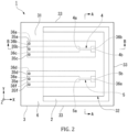
- FIG. 2 is a plan view illustrating the pressure sensing unit in the resonant pressure sensors 1A, 1B illustrated in FIGS. 1A-1B
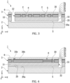
- FIG. 3 is a sectional view along line A-A of FIG. 2
- FIG. 4 is a sectional view along line B-B of FIG. 2 .
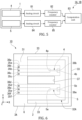
- FIG. 5 is a block diagram illustrating signal processing operations in the resonant pressure sensors 1A, 1B.
- the resonant pressure sensor 1A of one or more embodiments includes a pressure sensing unit 1 that can detect a static pressure based on a change value of a resonance frequency. It also has a base substrate (housing-fixed portion) 2, a support substrate (substrate portion) 3, and the pressure-receiving fluid F, which is interposed in a gap S between the base substrate 2 and the support substrate 3 and envelops the support substrate 3.
- the support substrate 3 has a fixed portion (substrate-fixed portion) 31, in at least one location or more, that is fixed to the base substrate 2.
- the substrate portion may be referred to as a substrate.
- the resonant pressure sensor 1A of one or more embodiments includes a second resonator 5 that is disposed in the separated portion 32 of the support substrate 3.
- a change amount (pressure sensitivity) of a resonance frequency thereof that changes based on a strain that arises according to the static pressure applied to the support substrate 3 by the pressure-receiving fluid F is less than a change amount (pressure sensitivity) of the resonance frequency of the first resonator 4.
- the active layer 3c is doped single-crystal silicon and is a layer having a uniform boron concentration of, for example, about 1 ⁇ 10 17 to 1 ⁇ 10 18 cm -3 .
- the impurity diffusion layer 3d is a layer wherein boron (B) is diffused at a high concentration as an impurity in the active layer 3c.
- the first resonator 4 is made of a semiconductor material including an impurity, a concentration of the impurity is 1 ⁇ 10 20 cm -3 or higher, and an atomic radius of the impurity is smaller than an atomic radius of silicon, which is the base material.
- the impurity included in the first resonator 4 for example, boron (B) and phosphorous (P) can be mentioned.
- B boron
- P phosphorous
- the impurity whose atomic radius is smaller than the silicon constituting the first resonator 4 replaces this silicon, the first resonator 4 deforms to relax this lattice strain.
- fixed ends 4a, 4b of the first resonator 4 are fixed, a tensile stress acts on / is imparted to the first resonator 4 in advance.
- a resonant pressure sensor provided with the H-shaped resonator of non-patent literature 1
- boron at a concentration of 1 ⁇ 10 20 cm -3 or higher at a selective epitaxial step of forming the resonator
- a pressure sensor that can measure high static pressure can be realized while preventing buckling of the resonator.
- the second resonator 5 is formed in a linear shape extending in the X direction by machining the single-crystal silicon forming the active layer 3c provided on the support layer 3a forming the support substrate 3 and is formed in a position of the active layer 3c in the Z direction.
- the resonance frequencies of the first resonator 4 and the second resonator 5 change according to the pressure and according to a change in Young's modulus or a difference in linear expansion coefficients between materials according to the internal temperature of the pressure sensing unit 1 (temperature substantially equal to a temperature of the first resonator 4 and a temperature of the second resonator 5).
- the internal temperature of the pressure sensing unit 1 temperature detection signal
- a more accurate pressure value applied to the pressure sensing unit 1 can be determined from the determined internal temperature and the change value of the resonance frequency of the first resonator 4 (pressure detection signal).
- the resonant pressure sensor 1A in the example illustrated in FIG. 1A houses the pressure-receiving fluid F, which is isolated from the measurement target by a pressure-propagating partition-wall member 52, inside the housing 50. It is used, for example, in a use of measuring a static pressure (pressure) in a state wherein a high static pressure from a fluid is applied.
- the resonant pressure sensor 1A in the illustrated example provides the pressure-propagating partition-wall member 52 in a through hole 51 provided in a top-plate portion of the housing 50.
- a metal material, a resin material, or the like that is conventionally used in this field can be adopted without any restrictions whatsoever.
- the computation unit 83 uses the digital signal input from the frequency counter 85, which has a frequency according to the internal temperature from the second resonator 5, as the temperature correction signal and performs temperature correction of the detection result of the pressure sensing unit 1 according to the internal temperature of the pressure sensing unit 1 determined from this signal.
- the support substrate 3 which has the fixed portion 31, which is fixed to the base substrate 2, and the separated portion 32, and the first resonator 4 that is disposed in the separated portion 32 of the support substrate 3 and has a resonance frequency that changes based on a strain that arises according to a static pressure applied to the support substrate 3 by the pressure-receiving fluid F.
- This enables high linearity and excellent measurement precision to be obtained regardless of a magnitude of a static pressure applied by a liquid, gas, or the like that is a measurement target.
- FIG. 6 only a pressure sensing unit 10 provided in the resonant pressure sensor of the second embodiment is illustrated, and illustration of, for example, the housing and the pressure-receiving fluid is omitted.
- the strain-mitigating hole 37 is disposed in the support substrate 3A, a strain that can be propagated from the base substrate 2 to the separated portion 32A via the fixed portion 31 and a strain that can be propagated in the separated portion 32A are absorbed by the strain-mitigating hole 37.
- the resonant pressure sensor of the third embodiment is detailed below while mainly referring to FIG. 7 .
- FIG. 7 as well, like the resonant pressure sensor of the second embodiment illustrated in FIG. 6 , only a pressure sensing unit 10A provided in the resonant pressure sensor of the third embodiment is illustrated, and illustration of the housing, the pressure-receiving fluid, and the like is omitted.
- FIG. 7 is a plan view for describing the pressure sensing unit 10A provided in the resonant pressure sensor of the third embodiment.
- the resonant pressure sensor of one or more embodiments differs from the resonant pressure sensor 1A and the like of the first and second embodiments above in that in a support substrate (substrate portion) 3B provided in the pressure sensing unit 10A, the first resonator 4 and the second resonator 5 are each disposed in a separated portion (substrate-separated portion) 32B or a separated portion (substrate-separated portion) 32C that differ.
- the support substrate 3B includes two separated portions 32B, 32C, and the first resonator 4 or the second resonator 5 is disposed in each.
- the support substrate 3B may further include another substrate-separated portion (32B or 32C).
- the separated portion 32B and the separated portion 32C are arranged parallel to each other while being separated in the Y direction. Moreover, the separated portion 32B and the separated portion 32C are aligned so as to be roughly in the same position and have roughly the same size in an extending direction thereof (X direction).
- the resonant pressure sensor of the fourth embodiment is detailed below while mainly referring to FIG. 8 to FIG. 10 .
- FIG. 8 to FIG. 10 as well, like the resonant pressure sensors of the second and third embodiments illustrated in FIG. 6 and FIG. 7 , only a pressure sensing unit 10B provided in the resonant pressure sensor of the fourth embodiment is illustrated, and illustration of the housing, the pressure-receiving fluid, and the like is omitted.
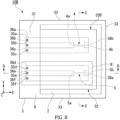
- FIG. 8 is a plan view for describing the pressure sensing unit 10B provided in the resonant pressure sensor of the fourth embodiment
- FIG. 9 is a sectional view along line C-C of FIG. 8
- FIG. 10 is a sectional view along line D-D of FIG. 8 .
- the first resonator 4 and the second resonator 5 are made of a single-crystal silicon material. Moreover, in the first resonator 4 and the second resonator 5 in the pressure sensing unit 10B, the impurity concentrations in each are values that differ by at least one order of magnitude or more when the unit is cm -3 . Moreover, the pressure sensing unit 10B is configured so a temperature coefficient of the resonance frequency of the second resonator 5 is greater than a temperature coefficient of the resonance frequency of the first resonator 4.
- the above temperature coefficient of the resonance frequency is a rate of change of the resonance frequency per unit temperature, and the unit thereof is, for example, (ppm/°C).
- the impurity concentration of one among the first resonator 4 and second resonator 5 made of the single-crystal silicon material is [a ⁇ 10 n cm -3 ]
- the impurity concentration of the other among these is [a ⁇ 10 n-1 cm -3 ] or less or [a ⁇ 10 n+1 cm -3 ] or more.
- the resonant pressure sensor of one or more embodiments is configured to make the temperature coefficients of the resonance frequencies different by a processing flow, whose illustration is omitted, wherein an impurity of a high concentration is diffused in the first resonator 4 and no impurity diffusion is performed in the second resonator 5. That is, in one or more embodiments, no impurity diffusion is performed in a non-diffusion region R-that is, a region near the second resonator 5-of the support substrate 3 illustrated in FIG. 8 .
- the impurity diffusion layer 3d is formed in a periphery of the first resonator 4 in the support substrate 3, but the impurity diffusion layer 3d is not formed in a periphery of the second resonator 5. This enables the pressure sensing unit 10B to have a configuration wherein the impurity concentrations greatly differ between the first resonator 4 and the second resonator 5.
- a temperature coefficient of a resonance frequency of a resonator changes according to a concentration and type of an impurity included in the resonator, a crystal orientation of a material constituting the resonator, and a resonance mode of the resonator used in pressure measurement.
- the temperature coefficient of the resonance frequency of the second resonator 5 is made greater than the temperature coefficient of the resonance frequency of the first resonator 4 by setting the impurity concentrations [cm -3 ] at values that differ by at least one order of magnitude or more between the first resonator 4 and the second resonator 5.
- the change amount of the resonance frequency of the second resonator 5 becomes greater than the change amount of the resonance frequency of the first resonator 4. That is, because a temperature sensitivity of the second resonator 5 becomes higher than a temperature sensitivity of the first resonator 4, in pressure measurement using the first resonator 4, temperature correction according to temperature measurement using the second resonator 5 (temperature correction using the internal temperature calculated from the resonance frequencies in the two resonators s (the first resonator 4 and the second resonator 5)) can be performed with high precision. Therefore, temperature-correction precision in pressure measurement using the first resonator 4 is improved.
- a thickness dimension of the second resonator 5 along a thickness direction of the support substrate 3 is greater than a thickness dimension of the first resonator 4. That is, a thickness dimension of the second resonator 5 in the stacking direction of the support substrate 3-that is, the Z direction-may be greater than the thickness dimension of the first resonator 4. Adopting this configuration further increases measurement precision of the internal temperature by the second resonator 5 and also improves temperature-correction precision. As a result, measurement precision of pressure by the pressure sensing unit 1 is also increased.
- the above configuration wherein the thickness dimension of the second resonator 5 is greater than the thickness dimension of the first resonator 4 is dependent on conditions of the manufacturing process described below.
- a mask made of a thermal oxide film is formed on this region.
- the above thickness dimension of the first resonator 4 becomes smaller than an original thickness of the active layer.
- the thickness dimension of the second resonator 5 becomes equal to the original thickness of the active layer. This causes the thickness dimension of the second resonator 5 to become greater than the thickness dimension of the first resonator 4.
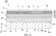
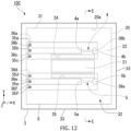
- the resonant pressure sensor of the fifth embodiment is detailed below while mainly referring to FIG. 11 and FIG. 12 .
- FIG. 11 and FIG. 12 as well, like the resonant pressure sensors of the second to fourth embodiments illustrated in FIG. 6 to FIG. 10 , only a pressure sensing unit 10C provided in the resonant pressure sensor of the fifth embodiment is illustrated, and illustration of the housing, the pressure-receiving fluid, and the like is omitted.
- the pressure sensing unit 10C which has a base substrate (substrate portion) 2A and a support substrate (support portion) 3C, is further provided with the pedestal (fixed substrate (housing-fixed portion)) 53, whereto the base substrate 2A is fixed.
- the base substrate 2A has a fixed portion (substrate-fixed portion) 21, in at least one location or more, that is fixed to a surface 53a of the pedestal 53. It also has separated portions (substrate-separated portion) 22, 23 that are separated from the pedestal 53 by a distance S in the Z direction and extend from the fixed portion 21 along the surface 53a (direction intersecting the Z direction; for example, the X direction).
- the base substrate 2A is configured as a cantilever structure wherein the fixed portion 21 is a support point and the separated portion 22 and the separated portion 23 are free ends.
- the resonant pressure sensor is configured so the pressure-receiving fluid, whose illustration is omitted in FIG. 11 , envelops the base substrate 2A (separated portion 22 and separated portion 23) while being interposed in the gap S between the pedestal 53 and the base substrate 2A.
- the resonance frequency of the first resonator 4 changes based on a strain arising according to a static pressure applied to the support substrate 3C by the pressure-receiving fluid. This enables high linearity and excellent measurement precision to be obtained regardless of a magnitude of a static pressure applied by a liquid, gas, or the like that is a measurement target.
- the resonant pressure sensor of one or more embodiments is configured so the base substrate 2A has the separated portions 22, 23 relative to the pedestal 53.
- the support substrate 3C may be provided with a separated portion described in the first to fourth embodiments but does not need to be provided with such.
- FIG. 11 illustrates a separated portion is also provided between the support substrate 3C and the concave portion 20a of the base substrate 2A.
- a material such as a single-crystal silicon wafer can be used as the pedestal 53 without any restrictions whatsoever.
- At least one among a concave strain-isolating groove 24 and a strain-isolating hole 25 that penetrates the base substrate 2A may be provided in at least a portion of the separated portions 22, 23 in the base substrate 2A.
- the concave strain-isolating groove 24 is disposed in one location of the separated portion 22 so as to be opened toward a pedestal 53 side, and the strain-isolating hole 25 is disposed in one location of the separated portion 23.
- strain-isolating groove 24 and strain-isolating hole 25 are provided in the base substrate 2A, a strain that can be propagated from the pedestal 53 to the support substrate 3C via the base substrate 2A (separated portion 22 and separated portion 23) and a strain that can be propagated in the base substrate 2A are absorbed by the strain-isolating groove 24 or the strain-isolating hole 25. This suppresses (reduces) a strain propagated from the pedestal 53 to the support substrate 3C via the base substrate 2A (separated portion 22 and separated portion 23) and the strain that can be propagated in the base substrate 2A.
- the separated portion in the support substrate or the base substrate has a so-called cantilever structure supported by the base substrate or the pedestal (fixed substrate) at one fixed portion, but the present invention is not limited thereto.
- a configuration wherein the separated portion is supported at two or more fixed portions can also be adopted.
- the configuration adopted in the resonant pressure sensor according to one or more embodiments - wherein the support substrate includes the separated portion having the gap between itself and the base substrate and a resonator is disposed in this separated portion- can also be applied in, for example, a resonant pressure sensor provided with a resonator having an H shape in a plan view (H-shaped resonator; for example, see FIGS. 1A-1B in non-patent literature 1 above).
- actions and effects similar to those of the above embodiments can be obtained by providing, instead of a resonator described in the above embodiments, the above H-shaped resonator in spaces that are the separated portions 32, 32A, 32B, 32C in the support substrates 3, 3A, 3B, 3C and are vacuum-sealed by the shell 6.
- the resonant pressure sensor according to one or more embodiments has high linearity and excellent measurement precision regardless of a magnitude of a static pressure applied by a fluid or the like that is a measurement target. Therefore, the resonant pressure sensor according to one or more embodiments is particularly useful in a use wherein a high static pressure is applied.
Landscapes
- Physics & Mathematics (AREA)
- General Physics & Mathematics (AREA)
- Measuring Fluid Pressure (AREA)
- Pressure Sensors (AREA)
Claims (8)
- Resonanzdrucksensor (1A; 1B) einer Druckerfassungseinheit (1), aufweisend:ein Gehäuse (50);einen gehäusefesten Bereich (2), der an dem Gehäuse (50) befestigt ist;ein Substrat (3; 3A; 3B; 3C), das folgendes aufweist:einen substratfesten Bereich (31), der an dem gehäusefesten Bereich (2) befestigt ist; undeinen substratgetrennten Bereich (32; 32A; 32B; 32C), der von dem gehäusefesten Bereich (2) getrennt ist und sich von dem substratfesten Bereich (31) erstreckt, wobeiein Spalt (S) zwischen dem gehäusefesten Bereich (2) und dem Substrat (3; 3A; 3B; 3C) ausgebildet ist, wobei der Spalt (S) zur Aufnahme eines druckaufnehmenden Fluids (F; K) ausgebildet ist, welches das Substrat (3; 3A; 3B; 3C) umhüllt;einen ersten Resonanzkörper (4), der in dem substratgetrennten Bereich (32; 32A; 32B; 32C) angeordnet und derart ausgebildet ist, dass er eine Änderung einer ersten Resonanzfrequenz basierend auf einer Dehnung in dem Substrat (3; 3A; 3B; 3C) erfasst, die durch einen statischen Druck verursacht wird, der von dem druckaufnehmenden Fluid (F; K) zugeführt wird;wobei der Resonanzdrucksensor gekennzeichnet ist durch einen zweiten Resonator (5), der in dem Substrat (3) angeordnet ist, wobei der zweite Resonator (5) konfiguriert ist, um eine Änderung einer zweiten Resonanzfrequenz basierend auf der Dehnung in dem Substrat (3) zu erfassen, die durch den statischen Druck verursacht wird, der von dem druckaufnehmenden Fluid (F) zugeführt wird, und wobeider zweite Resonanzkörper (5) eine Druckempfindlichkeit gegenüber der zweiten Resonanzfrequenz aufweist, die sich in Abhängigkeit von einer Innentemperatur der Druckerfassungseinheit (1) von einer Druckempfindlichkeit gegenüber der ersten Resonanzfrequenz des ersten Resonanzkörpers (4) unterscheidet; undeinen Prozessor, der derart ausgebildet ist, dass er den statischen Druck basierend auf der erfassten Änderung der ersten Resonanzfrequenz misst und den statischen Druck gemäß der Innentemperatur des Drucksensors basierend auf der Differenz zwischen der zweiten Resonanzfrequenz und der ersten Resonanzfrequenz korrigiert.
- Resonanzdrucksensor (1A; 1B) nach Anspruch 1, wobei das Substrat (3) eine Kragträgerstruktur aufweist, deren Auflagerpunkt der substratfeste Bereich (31) ist.
- Resonanzdrucksensor (1A; 1B) nach Anspruch 1 oder Anspruch 2, wobei das Substrat (3A) eine das Substrat (3) durchdringende spannungsmindernde Öffnung (37) aufweist.
- Resonanzdrucksensor (1A; 1B) nach einem der Ansprüche 1 bis 3, wobeider erste Resonanzkörper (4) aus einem Halbleitermaterial hergestellt ist, welches eine Verunreinigung aufweist,eine Konzentration der Verunreinigung 1×1020 cm-3 oder höher ist undein Atomradius der Verunreinigung kleiner als der Atomradius des Halbleitermaterials ist.
- Resonanzdrucksensor (1B) nach Anspruch 1, wobeidas Substrat (3B) ferner einen weiteren substratgetrennten Bereich (32B, 32C) aufweist, undder zweite Resonator (5) in dem weiteren substratgetrennten Bereich (32B, 32C) angeordnet ist.
- Resonanzdrucksensor (1A; 1B) nach Anspruch 1 oder Anspruch 5, wobeider erste Resonanzkörper (4) und der zweite Resonator (5) aus einem einkristallinen Siliziummaterial hergestellt sind, welches eine Verunreinigung aufweist,eine Konzentration der Verunreinigung in dem ersten Resonanzkörper (4) sich von einer Konzentration der Verunreinigung in dem zweiten Resonator (5) um eine oder mehrere Größenordnungen unterscheidet, wenn die Einheit in cm-3 ausgedrückt wird, undder zweite Resonator (5) einen Temperaturkoeffizienten der Resonanzfrequenz aufweist, der größer als ein Temperaturkoeffizient der Resonanzfrequenz des ersten Resonators (4) ist.
- Resonanzdrucksensor (1A; 1B) nach Anspruch 1 oder Anspruch 5, wobei entlang einer Dickenrichtung des Substrats (3) eine Dickendimension des zweiten Resonanzkörpers (5) größer als eine Dickendimension des ersten Resonanzkörpers (4) ist.
- Resonanzdrucksensor nach einem der Ansprüche 1 bis 7, wobeidas Substrat ferner folgendes aufweist:ein Basissubstrat (2A), welches den substratfesten Bereich aufweist, wobei das Basissubstrat (2A) an dem gehäusefesten Bereich befestigt ist; undein Trägersubstrat (3C), welches mit dem Basissubstrat (2A) verbunden ist;einen festen Bereich, welcher an dem Basissubstrat (2A) befestigt ist; undeinen getrennten Bereich, welcher von dem Basissubstrat (2A) getrennt ist und sich von dem festen Bereich erstreckt, undein Spalt zwischen dem Basissubstrat (2A) und dem Trägersubstrat (3C) ausgebildet ist, wobei der Spalt zur Aufnahme des druckaufnehmenden Fluids bestimmt ist, welches den getrennten Bereich umhüllt.
Priority Applications (2)
| Application Number | Priority Date | Filing Date | Title |
|---|---|---|---|
| EP26162510.7A EP4746291A2 (de) | 2020-01-10 | 2021-01-06 | Resonanter drucksensor |
| EP23153544.4A EP4212842B1 (de) | 2020-01-10 | 2021-01-06 | Resonanter drucksensor |
Applications Claiming Priority (1)
| Application Number | Priority Date | Filing Date | Title |
|---|---|---|---|
| JP2020002784A JP7216921B2 (ja) | 2020-01-10 | 2020-01-10 | 振動式圧力センサ |
Related Child Applications (2)
| Application Number | Title | Priority Date | Filing Date |
|---|---|---|---|
| EP23153544.4A Division EP4212842B1 (de) | 2020-01-10 | 2021-01-06 | Resonanter drucksensor |
| EP23153544.4A Division-Into EP4212842B1 (de) | 2020-01-10 | 2021-01-06 | Resonanter drucksensor |
Publications (2)
| Publication Number | Publication Date |
|---|---|
| EP3848685A1 EP3848685A1 (de) | 2021-07-14 |
| EP3848685B1 true EP3848685B1 (de) | 2023-03-08 |
Family
ID=74105845
Family Applications (3)
| Application Number | Title | Priority Date | Filing Date |
|---|---|---|---|
| EP23153544.4A Active EP4212842B1 (de) | 2020-01-10 | 2021-01-06 | Resonanter drucksensor |
| EP26162510.7A Pending EP4746291A2 (de) | 2020-01-10 | 2021-01-06 | Resonanter drucksensor |
| EP21150413.9A Active EP3848685B1 (de) | 2020-01-10 | 2021-01-06 | Resonanzdrucksensor |
Family Applications Before (2)
| Application Number | Title | Priority Date | Filing Date |
|---|---|---|---|
| EP23153544.4A Active EP4212842B1 (de) | 2020-01-10 | 2021-01-06 | Resonanter drucksensor |
| EP26162510.7A Pending EP4746291A2 (de) | 2020-01-10 | 2021-01-06 | Resonanter drucksensor |
Country Status (4)
| Country | Link |
|---|---|
| US (3) | US11428594B2 (de) |
| EP (3) | EP4212842B1 (de) |
| JP (1) | JP7216921B2 (de) |
| CN (2) | CN116698232A (de) |
Families Citing this family (1)
| Publication number | Priority date | Publication date | Assignee | Title |
|---|---|---|---|---|
| JP7216921B2 (ja) * | 2020-01-10 | 2023-02-02 | 横河電機株式会社 | 振動式圧力センサ |
Family Cites Families (32)
| Publication number | Priority date | Publication date | Assignee | Title |
|---|---|---|---|---|
| JPS55110404A (en) | 1979-02-19 | 1980-08-25 | Citizen Watch Co Ltd | Oscillation circuit |
| FR2532047A1 (fr) * | 1982-08-19 | 1984-02-24 | Asulab Sa | Capteur de mesure muni d'un resonateur piezo-electrique compense en temperature |
| US5188983A (en) * | 1990-04-11 | 1993-02-23 | Wisconsin Alumni Research Foundation | Polysilicon resonating beam transducers and method of producing the same |
| US5165289A (en) * | 1990-07-10 | 1992-11-24 | Johnson Service Company | Resonant mechanical sensor |
| US5511427A (en) * | 1993-07-21 | 1996-04-30 | Honeywell Inc. | Cantilevered microbeam temperature sensor |
| JP3254113B2 (ja) * | 1994-08-30 | 2002-02-04 | セイコーインスツルメンツ株式会社 | 加速度センサ |
| US5747705A (en) * | 1996-12-31 | 1998-05-05 | Honeywell Inc. | Method for making a thin film resonant microbeam absolute |
| JP3376925B2 (ja) * | 1998-08-11 | 2003-02-17 | 株式会社豊田中央研究所 | 振動型半導体センサ及びその製造方法 |
| JP2004077428A (ja) * | 2002-08-22 | 2004-03-11 | Mitsubishi Electric Corp | 圧力センサ |
| US7443509B1 (en) * | 2004-12-12 | 2008-10-28 | Burns David W | Optical and electronic interface for optically coupled resonators |
| GB2426336A (en) * | 2005-05-20 | 2006-11-22 | Transense Technologies Plc | SAW based torque and temperature sensor |
| US7806586B2 (en) * | 2006-06-02 | 2010-10-05 | The Board Of Trustees Of The Leland Stanford Junior University | Composite mechanical transducers and approaches therefor |
| US20090120169A1 (en) * | 2007-11-12 | 2009-05-14 | Chandler Jr William H | Fluid sensor and methods of making components thereof |
| JP4973718B2 (ja) * | 2009-01-27 | 2012-07-11 | セイコーエプソン株式会社 | 圧力検出ユニット、及び圧力センサー |
| US20110227451A1 (en) * | 2010-03-18 | 2011-09-22 | Seiko Epson Corporation | Resonator body, resonator device, and electronic device |
| CN102297741B (zh) * | 2010-06-25 | 2013-06-05 | 中国科学院电子学研究所 | 一种基于微电子机械技术的硅谐振式气压传感器 |
| JP5158160B2 (ja) * | 2010-09-10 | 2013-03-06 | 横河電機株式会社 | 振動式トランスデューサ |
| JP5656070B2 (ja) * | 2010-12-22 | 2015-01-21 | 横河電機株式会社 | 振動式絶対圧トランスデューサ |
| JP2012150029A (ja) * | 2011-01-20 | 2012-08-09 | Yokogawa Electric Corp | 振動式トランスデューサおよび振動式トランスデューサの製造方法 |
| CN102288516B (zh) * | 2011-06-29 | 2013-03-13 | 西安交通大学 | 基于mems技术的同时测量流体密度、压力和温度的集成流体传感器 |
| FR2977319B1 (fr) * | 2011-07-01 | 2014-03-14 | Commissariat Energie Atomique | Dispositif de mesure de pression a sensiblite optimisee |
| WO2013132842A1 (ja) * | 2012-03-07 | 2013-09-12 | パナソニック株式会社 | 荷重センサ |
| EP2637007B1 (de) * | 2012-03-08 | 2020-01-22 | ams international AG | Kapazitativer MEMS-Drucksensor |
| JP5807664B2 (ja) * | 2013-08-07 | 2015-11-10 | 横河電機株式会社 | 振動式トランスデューサおよびその製造方法 |
| CN103439032B (zh) * | 2013-09-11 | 2015-06-10 | 中国电子科技集团公司第四十九研究所 | 硅微谐振器的加工方法 |
| JP2015114108A (ja) * | 2013-12-09 | 2015-06-22 | パナソニックIpマネジメント株式会社 | 共振センサ |
| WO2015089175A1 (en) * | 2013-12-11 | 2015-06-18 | The Board Of Regents Of The University Of Texas System | Devices and methods for parameter measurement |
| CN103983395B (zh) * | 2014-05-30 | 2016-04-27 | 西安交通大学 | 一种微压力传感器及其制备与检测方法 |
| US9778238B2 (en) * | 2014-09-09 | 2017-10-03 | Ams International Ag | Resonant CO2 sensing with mitigation of cross-sensitivities |
| DE102016111909B4 (de) * | 2016-06-29 | 2020-08-13 | Infineon Technologies Ag | Mikromechanische Struktur und Verfahren zu ihrer Herstellung |
| CN107894297B (zh) * | 2017-11-07 | 2020-02-18 | 无锡必创传感科技有限公司 | 一种压力传感器芯片及其制造方法 |
| JP7216921B2 (ja) * | 2020-01-10 | 2023-02-02 | 横河電機株式会社 | 振動式圧力センサ |
-
2020
- 2020-01-10 JP JP2020002784A patent/JP7216921B2/ja active Active
-
2021
- 2021-01-06 EP EP23153544.4A patent/EP4212842B1/de active Active
- 2021-01-06 EP EP26162510.7A patent/EP4746291A2/de active Pending
- 2021-01-06 EP EP21150413.9A patent/EP3848685B1/de active Active
- 2021-01-07 US US17/143,517 patent/US11428594B2/en active Active
- 2021-01-08 CN CN202310681339.1A patent/CN116698232A/zh active Pending
- 2021-01-08 CN CN202110024926.4A patent/CN113188690B/zh active Active
-
2022
- 2022-06-30 US US17/854,209 patent/US11592347B2/en active Active
-
2023
- 2023-01-27 US US18/160,632 patent/US11815420B2/en active Active
Non-Patent Citations (1)
| Title |
|---|
| IKEDA K ET AL: "Three-dimensional micromachining of silicon pressure sensor integrating resonant strain gauge on diaphragm", SENSORS AND ACTUATORS A: PHYSICAL, ELSEVIER BV, NL, vol. 23, no. 1-3, 1 April 1990 (1990-04-01), pages 1007 - 1010, XP026597741, ISSN: 0924-4247, [retrieved on 19900401], DOI: 10.1016/0924-4247(90)87078-W * |
Also Published As
| Publication number | Publication date |
|---|---|
| JP7216921B2 (ja) | 2023-02-02 |
| EP4212842B1 (de) | 2026-04-15 |
| US20220349766A1 (en) | 2022-11-03 |
| CN116698232A (zh) | 2023-09-05 |
| EP4746291A2 (de) | 2026-05-20 |
| CN113188690A (zh) | 2021-07-30 |
| EP3848685A1 (de) | 2021-07-14 |
| US20210215560A1 (en) | 2021-07-15 |
| US11428594B2 (en) | 2022-08-30 |
| CN113188690B (zh) | 2023-07-04 |
| JP2021110637A (ja) | 2021-08-02 |
| EP4212842A1 (de) | 2023-07-19 |
| US11592347B2 (en) | 2023-02-28 |
| US11815420B2 (en) | 2023-11-14 |
| US20230175908A1 (en) | 2023-06-08 |
Similar Documents
| Publication | Publication Date | Title |
|---|---|---|
| US11226251B2 (en) | Method of making a dual-cavity pressure sensor die | |
| CN105241600B (zh) | 一种mems压力计芯片及其制造工艺 | |
| US5417115A (en) | Dielectrically isolated resonant microsensors | |
| US11255740B2 (en) | Pressure gauge chip and manufacturing process thereof | |
| KR20070035498A (ko) | 압력 센서 | |
| US9567211B2 (en) | Micromechanical semiconductor sensing device | |
| US20120096945A1 (en) | Pressure sensor | |
| CN101960276B (zh) | 压力传感器及其制造方法 | |
| US11815420B2 (en) | Resonant pressure sensor with improved linearity | |
| CN105388323B (zh) | 振动式传感器装置 | |
| JP7327695B2 (ja) | 振動式圧力センサ | |
| JPWO2005003711A1 (ja) | 水晶式圧力センサ、及びその製造方法 | |
| JP2018141720A (ja) | センシング装置、センシングシステム及びセンシング装置の製造方法 | |
| Mitsuhashi et al. | A resonant pressure sensor with super high resolution and stability based on novel volume shrinkage method | |
| Lin | 2000-Atmosphere Bulk-Type Dual-Cavity MEMS Pressure Sensor | |
| Han et al. | Getter-free MEMS capacitance diaphragm gauge with multi diaphragms | |
| JPH02262032A (ja) | 絶対圧型半導体圧力センサ | |
| JPH0483139A (ja) | 半導体歪みセンサ | |
| JPH0824197B2 (ja) | 圧力測定器 | |
| JPS62212539A (ja) | 半導体圧力センサ | |
| JP2003004568A (ja) | 静電容量型圧力センサ | |
| JPS63193025A (ja) | 圧力検知器 |
Legal Events
| Date | Code | Title | Description |
|---|---|---|---|
| PUAI | Public reference made under article 153(3) epc to a published international application that has entered the european phase |
Free format text: ORIGINAL CODE: 0009012 |
|
| STAA | Information on the status of an ep patent application or granted ep patent |
Free format text: STATUS: THE APPLICATION HAS BEEN PUBLISHED |
|
| AK | Designated contracting states |
Kind code of ref document: A1 Designated state(s): AL AT BE BG CH CY CZ DE DK EE ES FI FR GB GR HR HU IE IS IT LI LT LU LV MC MK MT NL NO PL PT RO RS SE SI SK SM TR |
|
| STAA | Information on the status of an ep patent application or granted ep patent |
Free format text: STATUS: REQUEST FOR EXAMINATION WAS MADE |
|
| 17P | Request for examination filed |
Effective date: 20220112 |
|
| RBV | Designated contracting states (corrected) |
Designated state(s): AL AT BE BG CH CY CZ DE DK EE ES FI FR GB GR HR HU IE IS IT LI LT LU LV MC MK MT NL NO PL PT RO RS SE SI SK SM TR |
|
| STAA | Information on the status of an ep patent application or granted ep patent |
Free format text: STATUS: EXAMINATION IS IN PROGRESS |
|
| 17Q | First examination report despatched |
Effective date: 20220519 |
|
| GRAP | Despatch of communication of intention to grant a patent |
Free format text: ORIGINAL CODE: EPIDOSNIGR1 |
|
| STAA | Information on the status of an ep patent application or granted ep patent |
Free format text: STATUS: GRANT OF PATENT IS INTENDED |
|
| INTG | Intention to grant announced |
Effective date: 20220914 |
|
| GRAS | Grant fee paid |
Free format text: ORIGINAL CODE: EPIDOSNIGR3 |
|
| GRAA | (expected) grant |
Free format text: ORIGINAL CODE: 0009210 |
|
| STAA | Information on the status of an ep patent application or granted ep patent |
Free format text: STATUS: THE PATENT HAS BEEN GRANTED |
|
| AK | Designated contracting states |
Kind code of ref document: B1 Designated state(s): AL AT BE BG CH CY CZ DE DK EE ES FI FR GB GR HR HU IE IS IT LI LT LU LV MC MK MT NL NO PL PT RO RS SE SI SK SM TR |
|
| REG | Reference to a national code |
Ref country code: CH Ref legal event code: EP Ref country code: AT Ref legal event code: REF Ref document number: 1552877 Country of ref document: AT Kind code of ref document: T Effective date: 20230315 |
|
| REG | Reference to a national code |
Ref country code: IE Ref legal event code: FG4D |
|
| REG | Reference to a national code |
Ref country code: DE Ref legal event code: R096 Ref document number: 602021001527 Country of ref document: DE |
|
| REG | Reference to a national code |
Ref country code: LT Ref legal event code: MG9D |
|
| P01 | Opt-out of the competence of the unified patent court (upc) registered |
Effective date: 20230603 |
|
| REG | Reference to a national code |
Ref country code: NL Ref legal event code: MP Effective date: 20230308 |
|
| PG25 | Lapsed in a contracting state [announced via postgrant information from national office to epo] |
Ref country code: RS Free format text: LAPSE BECAUSE OF FAILURE TO SUBMIT A TRANSLATION OF THE DESCRIPTION OR TO PAY THE FEE WITHIN THE PRESCRIBED TIME-LIMIT Effective date: 20230308 Ref country code: NO Free format text: LAPSE BECAUSE OF FAILURE TO SUBMIT A TRANSLATION OF THE DESCRIPTION OR TO PAY THE FEE WITHIN THE PRESCRIBED TIME-LIMIT Effective date: 20230608 Ref country code: LV Free format text: LAPSE BECAUSE OF FAILURE TO SUBMIT A TRANSLATION OF THE DESCRIPTION OR TO PAY THE FEE WITHIN THE PRESCRIBED TIME-LIMIT Effective date: 20230308 Ref country code: LT Free format text: LAPSE BECAUSE OF FAILURE TO SUBMIT A TRANSLATION OF THE DESCRIPTION OR TO PAY THE FEE WITHIN THE PRESCRIBED TIME-LIMIT Effective date: 20230308 Ref country code: HR Free format text: LAPSE BECAUSE OF FAILURE TO SUBMIT A TRANSLATION OF THE DESCRIPTION OR TO PAY THE FEE WITHIN THE PRESCRIBED TIME-LIMIT Effective date: 20230308 Ref country code: ES Free format text: LAPSE BECAUSE OF FAILURE TO SUBMIT A TRANSLATION OF THE DESCRIPTION OR TO PAY THE FEE WITHIN THE PRESCRIBED TIME-LIMIT Effective date: 20230308 |
|
| REG | Reference to a national code |
Ref country code: AT Ref legal event code: MK05 Ref document number: 1552877 Country of ref document: AT Kind code of ref document: T Effective date: 20230308 |
|
| PG25 | Lapsed in a contracting state [announced via postgrant information from national office to epo] |
Ref country code: SE Free format text: LAPSE BECAUSE OF FAILURE TO SUBMIT A TRANSLATION OF THE DESCRIPTION OR TO PAY THE FEE WITHIN THE PRESCRIBED TIME-LIMIT Effective date: 20230308 Ref country code: NL Free format text: LAPSE BECAUSE OF FAILURE TO SUBMIT A TRANSLATION OF THE DESCRIPTION OR TO PAY THE FEE WITHIN THE PRESCRIBED TIME-LIMIT Effective date: 20230308 Ref country code: GR Free format text: LAPSE BECAUSE OF FAILURE TO SUBMIT A TRANSLATION OF THE DESCRIPTION OR TO PAY THE FEE WITHIN THE PRESCRIBED TIME-LIMIT Effective date: 20230609 Ref country code: FI Free format text: LAPSE BECAUSE OF FAILURE TO SUBMIT A TRANSLATION OF THE DESCRIPTION OR TO PAY THE FEE WITHIN THE PRESCRIBED TIME-LIMIT Effective date: 20230308 |
|
| PG25 | Lapsed in a contracting state [announced via postgrant information from national office to epo] |
Ref country code: SM Free format text: LAPSE BECAUSE OF FAILURE TO SUBMIT A TRANSLATION OF THE DESCRIPTION OR TO PAY THE FEE WITHIN THE PRESCRIBED TIME-LIMIT Effective date: 20230308 Ref country code: RO Free format text: LAPSE BECAUSE OF FAILURE TO SUBMIT A TRANSLATION OF THE DESCRIPTION OR TO PAY THE FEE WITHIN THE PRESCRIBED TIME-LIMIT Effective date: 20230308 Ref country code: PT Free format text: LAPSE BECAUSE OF FAILURE TO SUBMIT A TRANSLATION OF THE DESCRIPTION OR TO PAY THE FEE WITHIN THE PRESCRIBED TIME-LIMIT Effective date: 20230710 Ref country code: EE Free format text: LAPSE BECAUSE OF FAILURE TO SUBMIT A TRANSLATION OF THE DESCRIPTION OR TO PAY THE FEE WITHIN THE PRESCRIBED TIME-LIMIT Effective date: 20230308 Ref country code: CZ Free format text: LAPSE BECAUSE OF FAILURE TO SUBMIT A TRANSLATION OF THE DESCRIPTION OR TO PAY THE FEE WITHIN THE PRESCRIBED TIME-LIMIT Effective date: 20230308 Ref country code: AT Free format text: LAPSE BECAUSE OF FAILURE TO SUBMIT A TRANSLATION OF THE DESCRIPTION OR TO PAY THE FEE WITHIN THE PRESCRIBED TIME-LIMIT Effective date: 20230308 |
|
| PG25 | Lapsed in a contracting state [announced via postgrant information from national office to epo] |
Ref country code: SK Free format text: LAPSE BECAUSE OF FAILURE TO SUBMIT A TRANSLATION OF THE DESCRIPTION OR TO PAY THE FEE WITHIN THE PRESCRIBED TIME-LIMIT Effective date: 20230308 Ref country code: PL Free format text: LAPSE BECAUSE OF FAILURE TO SUBMIT A TRANSLATION OF THE DESCRIPTION OR TO PAY THE FEE WITHIN THE PRESCRIBED TIME-LIMIT Effective date: 20230308 Ref country code: IS Free format text: LAPSE BECAUSE OF FAILURE TO SUBMIT A TRANSLATION OF THE DESCRIPTION OR TO PAY THE FEE WITHIN THE PRESCRIBED TIME-LIMIT Effective date: 20230708 |
|
| REG | Reference to a national code |
Ref country code: DE Ref legal event code: R097 Ref document number: 602021001527 Country of ref document: DE |
|
| PLBE | No opposition filed within time limit |
Free format text: ORIGINAL CODE: 0009261 |
|
| STAA | Information on the status of an ep patent application or granted ep patent |
Free format text: STATUS: NO OPPOSITION FILED WITHIN TIME LIMIT |
|
| PG25 | Lapsed in a contracting state [announced via postgrant information from national office to epo] |
Ref country code: SI Free format text: LAPSE BECAUSE OF FAILURE TO SUBMIT A TRANSLATION OF THE DESCRIPTION OR TO PAY THE FEE WITHIN THE PRESCRIBED TIME-LIMIT Effective date: 20230308 Ref country code: DK Free format text: LAPSE BECAUSE OF FAILURE TO SUBMIT A TRANSLATION OF THE DESCRIPTION OR TO PAY THE FEE WITHIN THE PRESCRIBED TIME-LIMIT Effective date: 20230308 |
|
| 26N | No opposition filed |
Effective date: 20231211 |
|
| PG25 | Lapsed in a contracting state [announced via postgrant information from national office to epo] |
Ref country code: IT Free format text: LAPSE BECAUSE OF FAILURE TO SUBMIT A TRANSLATION OF THE DESCRIPTION OR TO PAY THE FEE WITHIN THE PRESCRIBED TIME-LIMIT Effective date: 20230308 |
|
| PG25 | Lapsed in a contracting state [announced via postgrant information from national office to epo] |
Ref country code: MC Free format text: LAPSE BECAUSE OF FAILURE TO SUBMIT A TRANSLATION OF THE DESCRIPTION OR TO PAY THE FEE WITHIN THE PRESCRIBED TIME-LIMIT Effective date: 20230308 |
|
| PG25 | Lapsed in a contracting state [announced via postgrant information from national office to epo] |
Ref country code: MC Free format text: LAPSE BECAUSE OF FAILURE TO SUBMIT A TRANSLATION OF THE DESCRIPTION OR TO PAY THE FEE WITHIN THE PRESCRIBED TIME-LIMIT Effective date: 20230308 |
|
| REG | Reference to a national code |
Ref country code: CH Ref legal event code: PL |
|
| PG25 | Lapsed in a contracting state [announced via postgrant information from national office to epo] |
Ref country code: LU Free format text: LAPSE BECAUSE OF NON-PAYMENT OF DUE FEES Effective date: 20240106 |
|
| PG25 | Lapsed in a contracting state [announced via postgrant information from national office to epo] |
Ref country code: LU Free format text: LAPSE BECAUSE OF NON-PAYMENT OF DUE FEES Effective date: 20240106 |
|
| PG25 | Lapsed in a contracting state [announced via postgrant information from national office to epo] |
Ref country code: BE Free format text: LAPSE BECAUSE OF NON-PAYMENT OF DUE FEES Effective date: 20240131 |
|
| PG25 | Lapsed in a contracting state [announced via postgrant information from national office to epo] |
Ref country code: CH Free format text: LAPSE BECAUSE OF NON-PAYMENT OF DUE FEES Effective date: 20240131 |
|
| PG25 | Lapsed in a contracting state [announced via postgrant information from national office to epo] |
Ref country code: CH Free format text: LAPSE BECAUSE OF NON-PAYMENT OF DUE FEES Effective date: 20240131 Ref country code: BE Free format text: LAPSE BECAUSE OF NON-PAYMENT OF DUE FEES Effective date: 20240131 |
|
| REG | Reference to a national code |
Ref country code: BE Ref legal event code: MM Effective date: 20240131 |
|
| PG25 | Lapsed in a contracting state [announced via postgrant information from national office to epo] |
Ref country code: BG Free format text: LAPSE BECAUSE OF FAILURE TO SUBMIT A TRANSLATION OF THE DESCRIPTION OR TO PAY THE FEE WITHIN THE PRESCRIBED TIME-LIMIT Effective date: 20230308 |
|
| PG25 | Lapsed in a contracting state [announced via postgrant information from national office to epo] |
Ref country code: BG Free format text: LAPSE BECAUSE OF FAILURE TO SUBMIT A TRANSLATION OF THE DESCRIPTION OR TO PAY THE FEE WITHIN THE PRESCRIBED TIME-LIMIT Effective date: 20230308 |
|
| PG25 | Lapsed in a contracting state [announced via postgrant information from national office to epo] |
Ref country code: IE Free format text: LAPSE BECAUSE OF NON-PAYMENT OF DUE FEES Effective date: 20240106 |
|
| PG25 | Lapsed in a contracting state [announced via postgrant information from national office to epo] |
Ref country code: IE Free format text: LAPSE BECAUSE OF NON-PAYMENT OF DUE FEES Effective date: 20240106 |
|
| PG25 | Lapsed in a contracting state [announced via postgrant information from national office to epo] |
Ref country code: CY Free format text: LAPSE BECAUSE OF FAILURE TO SUBMIT A TRANSLATION OF THE DESCRIPTION OR TO PAY THE FEE WITHIN THE PRESCRIBED TIME-LIMIT; INVALID AB INITIO Effective date: 20210106 |
|
| PG25 | Lapsed in a contracting state [announced via postgrant information from national office to epo] |
Ref country code: HU Free format text: LAPSE BECAUSE OF FAILURE TO SUBMIT A TRANSLATION OF THE DESCRIPTION OR TO PAY THE FEE WITHIN THE PRESCRIBED TIME-LIMIT; INVALID AB INITIO Effective date: 20210106 |
|
| PG25 | Lapsed in a contracting state [announced via postgrant information from national office to epo] |
Ref country code: TR Free format text: LAPSE BECAUSE OF FAILURE TO SUBMIT A TRANSLATION OF THE DESCRIPTION OR TO PAY THE FEE WITHIN THE PRESCRIBED TIME-LIMIT Effective date: 20230308 |
|
| PGFP | Annual fee paid to national office [announced via postgrant information from national office to epo] |
Ref country code: GB Payment date: 20251219 Year of fee payment: 6 |
|
| PGFP | Annual fee paid to national office [announced via postgrant information from national office to epo] |
Ref country code: FR Payment date: 20251217 Year of fee payment: 6 |
|
| PGFP | Annual fee paid to national office [announced via postgrant information from national office to epo] |
Ref country code: DE Payment date: 20251217 Year of fee payment: 6 |