EP3848153B1 - Dichtungsinstallationswerkzeug - Google Patents
Dichtungsinstallationswerkzeug Download PDFInfo
- Publication number
- EP3848153B1 EP3848153B1 EP21150219.0A EP21150219A EP3848153B1 EP 3848153 B1 EP3848153 B1 EP 3848153B1 EP 21150219 A EP21150219 A EP 21150219A EP 3848153 B1 EP3848153 B1 EP 3848153B1
- Authority
- EP
- European Patent Office
- Prior art keywords
- pusher
- seal
- base plate
- component
- tool
- Prior art date
- Legal status (The legal status is an assumption and is not a legal conclusion. Google has not performed a legal analysis and makes no representation as to the accuracy of the status listed.)
- Active
Links
Images


Classifications
-
- F—MECHANICAL ENGINEERING; LIGHTING; HEATING; WEAPONS; BLASTING
- F01—MACHINES OR ENGINES IN GENERAL; ENGINE PLANTS IN GENERAL; STEAM ENGINES
- F01D—NON-POSITIVE DISPLACEMENT MACHINES OR ENGINES, e.g. STEAM TURBINES
- F01D25/00—Component parts, details, or accessories, not provided for in, or of interest apart from, other groups
-
- B—PERFORMING OPERATIONS; TRANSPORTING
- B25—HAND TOOLS; PORTABLE POWER-DRIVEN TOOLS; MANIPULATORS
- B25B—TOOLS OR BENCH DEVICES NOT OTHERWISE PROVIDED FOR, FOR FASTENING, CONNECTING, DISENGAGING, OR HOLDING
- B25B27/00—Hand tools, specially adapted for fitting together or separating parts or objects whether or not involving some deformation, not otherwise provided for
- B25B27/0028—Tools for removing or installing seals
-
- B—PERFORMING OPERATIONS; TRANSPORTING
- B25—HAND TOOLS; PORTABLE POWER-DRIVEN TOOLS; MANIPULATORS
- B25H—WORKSHOP EQUIPMENT, e.g. FOR MARKING-OUT WORK; STORAGE MEANS FOR WORKSHOPS
- B25H3/00—Storage means or arrangements for workshops facilitating access to, or handling of, work tools or instruments
- B25H3/006—Storage means specially adapted for one specific hand apparatus, e.g. an electric drill
-
- B—PERFORMING OPERATIONS; TRANSPORTING
- B25—HAND TOOLS; PORTABLE POWER-DRIVEN TOOLS; MANIPULATORS
- B25H—WORKSHOP EQUIPMENT, e.g. FOR MARKING-OUT WORK; STORAGE MEANS FOR WORKSHOPS
- B25H3/00—Storage means or arrangements for workshops facilitating access to, or handling of, work tools or instruments
- B25H3/02—Boxes
-
- F—MECHANICAL ENGINEERING; LIGHTING; HEATING; WEAPONS; BLASTING
- F05—INDEXING SCHEMES RELATING TO ENGINES OR PUMPS IN VARIOUS SUBCLASSES OF CLASSES F01-F04
- F05D—INDEXING SCHEME FOR ASPECTS RELATING TO NON-POSITIVE-DISPLACEMENT MACHINES OR ENGINES, GAS-TURBINES OR JET-PROPULSION PLANTS
- F05D2230/00—Manufacture
- F05D2230/60—Assembly methods
Definitions
- the disclosure relates to an installation tool for installing a seal into a bore of a component.
- a bearing housing for a gas turbine engine includes a bore that receives a seal.
- An oil tube having a flange is bolted to a boss surrounding the bore such that the seal engages the oil tube.
- the seal can become damaged if alignment of the seal with respect to the bore is not maintained as the seal is pushed into the bore, creating a leak subsequent to assembly.
- One example tool is a one-piece 3-D printed tool with an annular flange extending from a base, which entirely circumscribes the flange.
- the seal is arranged on the flange, and the base is carefully bolted to the boss, forcing the seal into the bore.
- the bolts must either be tightened simultaneously or each a little bit at a time to ensure the seal alignment is maintained.
- Another seal installation tool includes a bracket that is secured to the boss using bolts.
- a handle is rotated to slide a block within the bracket.
- a separate seal pusher is arranged between the block through a hole in the bracket, which entirely circumscribes the hole. The seal is arranged on the pusher. Rotating the handle advances the pusher and seal into the bore.
- EP3756819 discloses a method of installing a seal in a bore of a component which includes securing a base plate to a component.
- the method includes arranging the seal onto a pusher.
- the method also includes inserting the pusher into a hole in the base plate.
- the method further includes installing a hub onto the base plate and over the pusher.
- the method further includes rotating a rod relative to the hub to advance the pusher and seat the seal in the bore.
- US2016/312656 discloses methods and tools for pressing a ring seal into a component.
- a tool is anchored to the component.
- the tool includes a first aperture which extends along an axis.
- the first aperture is coaxial with a second aperture in the component.
- the ring seal is pushed axially through the first aperture towards the component, where the tool radially compresses the ring seal as the ring seal moves axially towards the component.
- the radially compressed ring seal is pressed into the second aperture using the tool.
- WO86/05666 discloses a portable multi-purpose combination device for use in the performance of an activity, comprising two separable, inter-engaging constituent parts arranged to serve complementary functions relating to such activity.
- One said part comprises a base part constructed as a receptacle for holding articles, implements and/or materials required for or useful in the performance of said activity.
- the other part comprises a cover part arranged to removably fit over, protect, and be supported by said base part, and is constructed so as when removed from said base part to serve alternatively (a) as a seat, support, workbench, or step useful in the performance of the said activity, or (b) when inverted, as a temporary receptacle for materials useful in, associated with, or arising from the performance of said activity.
- GB2226807 discloses a tool chest that resembles a rectangular box when closed for transportation but when opened up becomes a work station on four legs and with hinged work platforms on which most tasks associated with building construction or DIY work may be performed. It has internal moulded profiles for tool storage and externally along one side enclosed storage for hand saws and on the opposite side a tool rack for use when being used as a work station. The entire assembly may be transported by means of a shoulder harness which is releasably attached to two moulded lugs in the upper central position on the two short sides.
- the four legs hinge within a recess in the base of the chest and each leg has a cushioning insert fixedly secured at the base to prevent slipping and to cushion impact and noise.
- DE3601230 discloses a box-like container having a receiving part and a lid for storing hand-held electric tools, other tools, screws, dowels or the like, in which the receiving part and the lid can be connected to one another in a positive-locking manner.
- the lid provides parallel longitudinal grooves with at least one undercut, and one side wall of the receiving part provides projections which are adapted to the longitudinal grooves and allow hooking-in and unhooking via a tilting and/or lifting movement.
- a method of installing a seal in a bore of a component comprising opening a tool case to reveal a support fixture with a shaped groove configured to receive a component flange and permit rotation of the component relative to the tool case and an orienting step comprising rotating the component in the support fixture while a portion of the component flange remains within the shaped groove.
- the method includes a securing step comprising securing a base plate to the component.
- the method includes arranging the seal onto a pusher.
- the method also includes inserting the pusher into a hole in the base plate.
- the method further includes an installing step comprising installing a hub onto the base plate and over the pusher.
- the method further includes a rotating step comprising rotating a rod relative to the hub to advance the pusher and seat the seal in the bore.
- the method includes the step of placing the component in the support fixture.
- the orienting step includes rotating the component about its axis to position the bore generally vertically.
- the component includes a perimeter flange.
- the orienting step includes sliding the flange within complementarily shaped groove in the support fixture.
- the securing step includes abutting a boss of the component with the base plate and the bore in the boss.
- the method includes a step of clamping the base plate to the boss by securing bolts to the base plate.
- the clamping step includes inserting the bolts from a side opposite the boss at an interior of the component.
- the securing step includes providing a window in the base plate that leaves the seal visible through the window subsequent to the inserting step.
- the method includes the step of observing longitudinal movement of the seal past the window toward the bore.
- the pusher includes first and second diameter portions that form a first shoulder.
- the arranging step includes sliding the seal onto the first diameter portion and into abutment with the first shoulder.
- the pusher includes a third diameter portion that forms a second shoulder with the second diameter portion.
- the hole includes a stop that abuts the second shoulder in a fully installed seal position.
- the pusher includes first and second pusher portions.
- the first and second diameter portions are provided on the first pusher portion.
- the third diameter portion is provided on the second pusher portion.
- the first and second pusher portions are secured to one another by a fastener.
- the rotating step slides the first diameter portion into the bore in a slip fit relationship.
- the installing step includes threading the hub onto a collar of the base plate and receiving an end of the rod in a pocket of the pusher in a slip fit relationship.
- the rotating step includes threadingly rotating the rod relative to the hub and tightening the rod until the second should contacts the stop.
- a seal installation tool comprising a tool case having a support fixture with a shaped groove that is configured to receive a component flange and permit rotation of a component relative to the tool case while a portion of the component flange remains within the shaped groove.
- the seal installation tool also includes a base plate having a hole.
- the base plate has a window that adjoins the hole.
- a pusher has first and second diameter portions that form a shoulder. The first diameter portion is configured to carry a seal against the shoulder.
- the pusher is arranged in the hole in a slip fit relationship.
- a hub is removeably secured to the base plate over the pusher.
- a rod is threadingly received by the hub for relative rotation thereto. An end of the rod cooperates with the pusher.
- the rod is configured to longitudinally slide the pusher relative to the base plate.
- the tool includes a tool tray that is arranged in the tool case over support fixture.
- the tool tray has cut-outs that removably hold the base plate and an assembly that includes the pusher, the hub and the rod.
- the base plate includes threaded holes that are configured to receive bolts that clamp the base plate to a component having a bore that receives the seal.
- the pusher includes a third diameter portion that forms a second shoulder with the second diameter portion.
- the hole includes a stop that abuts the second shoulder in a fully installed seal position.
- the pusher includes first and second pusher portions.
- the first and second diameter portions are provided on the first pusher portion.
- the third diameter portion is provided on the second pusher portion.
- the first and second pusher portions are secured to one another by a fastener.
- the first and second pusher portions are different materials.
- the pusher includes a pocket that receives an end of the rod in a slip fit relationship.
- the base plate includes a collar.
- the hub is threadingly secured to the collar.
- the seal is aligned with the window in an uninstalled seal position.
- a component 10 such as a gas turbine engine bearing housing, includes a perimeter flange 11.
- One or more bores 12 in the component 10 are used to communicate a fluid such as lubricating oil to the interior of the component.
- the component 10 includes a boss 20 providing a flat surface to which an oil tube is secured at holes 24, which may be threaded or non-threaded.
- the bore 12 includes an annular recess 14 providing a shoulder 16.
- a seal 18 is inserted into the bore 12 and is a small distance away from the shoulder 16 when in a fully installed position.
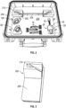
- a seal installation tool 26 which is included in a kit, is used to insert the seal 18 into the bore 12 while maintaining desired alignment, as shown in Figure 2 , which mitigates potential damage to the seal 18 during installation. Even with using the disclosed tool 26 for seal installation, the seal 18 may still catch on the corner of the bore 12 and damage the seal 18.
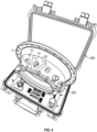
- the seal installation kit is shown in Figures 2-4 .
- the kit includes a tool case 200 that has the implements needed for damage-free seal installation.
- the tool case 200 has a support fixture 202 arranged within the case.
- the support fixture 202 has one or more legs 208 that extends from a base that provides a shaped groove 210.
- the legs 208 may be secured to the case 200 if desired.
- a foam shadow box or tool tray 204 is arranged over the legs 208, and the base extends through an opening 206 in the tool tray 204.
- the tool tray 204 which may be glued in place, has cut-outs in the shape of the various implements of the seal installation tool (e.g., tool 26, bolts 34, and base plates 28, 128).
- the shaped groove 210 in the base receives the flange 11 in such a manner so as to permit rotation of the component 10 relative to the tool case 200.
- the legs 208 prevent the support fixture 202 from tipping over.
- the tool case 200 is opened, and the flange 11 is inserted into the complementarily shaped groove 210.
- the component 10 is rotated to orient the boss 20 and its bore 12 in a generally vertical orientation. This prevents the seal 18 from gravitating to one side if, for example, the bore was oriented horizontally, which could result in misalignment and damage to the seal 18.
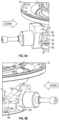
- the tool 26 includes a base plate 28 having standoffs 30 separated by a window 32 that provides an unobstructed view to an interior portion of the tool at an entrance to the bore 12.
- the seal 18 is mounted to a pusher 56 supported by the base plate 28.
- This window 32 provided on each of opposing sides of the base 28, for example, enables the operator to view the seal 18 as it moves longitudinally into the bore 12 during installation so that the seal 18 can be checked for proper alignment.
- FIG. 5B Another seal installation tool 126 having windows 132 is illustrated in Figure 5B .
- the tool 126 uses a different base plate 128 than that of the seal installation tool 26. Otherwise, all of the remaining components may be interchangeable such that a kit containing multiple base plates for a particular component may be provided.
- the base plate 28 includes a hole 31 that receives the pusher 56.
- the window 32 extends all the way to the hole 31 to provide visibility to an end of the pusher 56 on which the seal 18 is mounted.
- the base plate 28 is clamped to the boss 20 by bolts 34.
- a threaded end 36 of the bolts 34 is received in holes 33.
- a shank 38 on each bolt 34 has a shoulder 40 that engages a backside of the component 10.
- Knobs 42 may be provided on the bolts 34 to enable hand tightening by the operator.
- a collar 44 is provided on the base plate 28, and a hub 46 is threadingly secured to the collar 44 at a threaded inner diameter 48 of the hub 46.
- the hub 46 encloses the pusher 56.
- a rod 52 is threadingly received in a hole 50 of the hub 46 for relative rotation thereto.
- One end 53 of the rod 52 is received within a pocket 55 of the pusher 56 in a slip fit relationship.
- Another end 54 of the rod 52 is configured to cooperate with a tool, such as a torque wrench.
- the pusher 56 includes first and second pusher portions 58, 60, which are secured to one another by a fastener 62 in the example.
- the pusher 56 includes first and second diameter portions 64, 66 that form a shoulder 68.
- the seal 18 is arranged on the first diameter portion 64 and in abutment with the shoulder 68.
- a third diameter portion 70 forms a second shoulder 72 with the second diameter portion 66.
- the hole 31 in the base plate 28 provides a stop 74 against which the second shoulder 72 abuts during full extension of the pusher 56.
- the base plate 28 is secured to the component 10 using the bolts 34 to clamp the base plate 28 to the boss 20.
- the bolts 34 are inserted from a side opposite the boss 20 and the interior of the component 10.
- the seal 18 is arranged onto the pusher 56.
- the pusher 56 is inserted into the hole 31 in the base plate 28, and the hub 46 is installed onto the collar 44 and over the pusher 56. At this point, the seal 18 is visible through the windows 32.
- the rod 52 is rotated relative to the hub 46 to advance the pusher 56 and seat the seal 18 in the bore 12 while maintaining desired alignment.
- the end 53 of rod 52 spins freely within the pocket 55.
- the rod 52 is torqued by a tool (e.g., wrench) at the end 54 until it the shoulder 72 hits stop 74. This prevents the seal from rolling inward should the seal come in contact with the radius in the corner of shoulder 16.
- the torque measurement from the wrench is used to inform mechanic of potential damage to the seal.
- the tool 26 is removed from the boss 20, and proper seal installation can be confirmed.
Landscapes
- Engineering & Computer Science (AREA)
- Mechanical Engineering (AREA)
- General Engineering & Computer Science (AREA)
- Automatic Assembly (AREA)
- Hand Tools For Fitting Together And Separating, Or Other Hand Tools (AREA)
Claims (15)
- Verfahren zum Installieren einer Dichtung (18) in einer Bohrung (12) einer Komponente (10), wobei das Verfahren Folgendes umfasst:Öffnen eines Werkzeugkoffers (200), um eine Stützhalterung (202) mit einer geformten Nut (210) freizulegen, die dazu konfiguriert ist, einen Komponentenflansch (11) aufzunehmen und Drehung der Komponente (10) relativ zu dem Werkzeugkoffer (200) zu ermöglichen;Drehen der Komponente (10) in der Stützhalterung (202), während ein Abschnitt des Komponentenflansches (11) innerhalb der geformten Nut (210) bleibt;Befestigen einer Basisplatte (28) an der Komponente (10);Anordnen der Dichtung (18) auf einen Schieber (56);Einführen des Schiebers (56) in ein Loch in der Basisplatte (28) ;Installieren einer Nabe (46) auf der Basisplatte (28) und über dem Schieber (56); undDrehen einer Stange (52) relativ zu der Nabe (46), um den Schieber (56) vorzuschieben und die Dichtung (18) in der Bohrung (12) zu platzieren.
- Verfahren nach Anspruch 1, umfassend den Schritt des Platzierens der Komponente (10) in der Stützhalterung (202) und wobei der Ausrichtungsschritt Drehen der Komponente (10) um deren Achse beinhaltet, um die Bohrung (12) im Allgemeinen vertikal zu positionieren.
- Verfahren nach Anspruch 1 oder 2, wobei die Komponente (10) einen Umfangsflansch (11) beinhaltet und der Ausrichtungsschritt Schieben des Flansches (11) innerhalb einer komplementär geformten Nut in der Stützhalterung (202) beinhaltet.
- Verfahren nach einem der Ansprüche 1 bis 3, wobei der Befestigungsschritt eines oder mehrere von Anlegen eines Vorsprungs (20) der Komponente (10) an die Basisplatte (28) beinhaltet, wobei die Bohrung (12) in dem Vorsprung (20) angeordnet ist, und einen Schritt des Festklemmens der Basisplatte (28) an dem Vorsprung (20) durch Befestigen von Bolzen (34) an der Basisplatte (28) umfasst;der Befestigungsschritt Einführen der Bolzen (34) von einer Seite gegenüber dem Vorsprung (20) an einer Innenseite der Komponente (10) beinhaltet; undBereitstellen eines Fensters (32) in der Basisplatte (28), das die Dichtung (18) nach dem Einführungsschritt durch das Fenster (32) sichtbar lässt, und optional Beobachten der Längsbewegung der Dichtung (18) an dem Fenster (32) vorbei in Richtung der Bohrung (12).
- Verfahren nach einem der Ansprüche 1 bis 4, wobei der Schieber (56) einen ersten und einen zweiten Durchmesserabschnitt (64, 66) beinhaltet, die eine erste Schulter bilden, und der Anordnungsschritt Schieben der Dichtung (18) auf den ersten Durchmesserabschnitt (64) und anliegend an der ersten Schulter beinhaltet.
- Verfahren nach Anspruch 5, wobei der Schieber (56) einen dritten Durchmesserabschnitt (70) beinhaltet, der mit dem zweiten Durchmesserabschnitt (66) eine zweite Schulter (72) bildet, und das Loch einen Anschlag (74) beinhaltet, der in einer vollständig installierten Dichtungsposition an der zweiten Schulter (72) anliegt.
- Verfahren nach Anspruch 6, wobei der Schieber (56) einen ersten und einen zweiten Schieberabschnitt (58, 60) beinhaltet, der erste und der zweite Durchmesserabschnitt (64, 66) an dem ersten Schieberabschnitt (58) bereitgestellt sind und der dritte Durchmesserabschnitt (70) an dem zweiten Schieberabschnitt (60) bereitgestellt ist, wobei der erste und der zweite Schieberabschnitt (58, 60) durch ein Befestigungsmittel (62) aneinander befestigt sind.
- Verfahren nach Anspruch 6 oder 7, wobei der Drehschritt den ersten Durchmesserabschnitt (64) in einer Gleitsitzbeziehung in die Bohrung (12) schiebt.
- Verfahren nach einem der Ansprüche 1 bis 8, wobei der Installationsschritt Schrauben der Nabe (46) auf einen Kragen (44) der Basisplatte (28) und Aufnehmen eines Endes der Stange (52) in einer Tasche (55) des Schiebers (56) in einer Gleitsitzbeziehung beinhaltet.
- Verfahren nach Anspruch 9, wobei der Drehschritt Gewindedrehen der Stange (52) relativ zu der Nabe (46) und Festziehen der Stange (52), bis eine zweite Schulter (72) einen Anschlag (74) berührt, beinhaltet.
- Dichtungsinstallationswerkzeug (26), umfassend:einen Werkzeugkoffer (200), der eine Stützhalterung (202) mit einer geformten Nut aufweist, die dazu konfiguriert ist, einen Komponentenflansch (11) aufzunehmen und Drehung einer Komponente (10) relativ zu dem Werkzeugkoffer (200) zu ermöglichen, während ein Abschnitt des Komponentenflansches (11) innerhalb der geformten Nut (210) bleibt;eine Basisplatte (28), die ein Loch aufweist, wobei die Basisplatte (28) ein an das Loch angrenzendes Fenster (32) aufweist;einen Schieber (56), der einen ersten und einen zweiten Durchmesserabschnitt (64, 66) aufweist, die eine Schulter (16) bilden, wobei der erste Durchmesserabschnitt (64) dazu konfiguriert ist, eine Dichtung (18) gegen die Schulter (16) zu tragen, und der Schieber (56) in einer Gleitsitzbeziehung in dem Loch angeordnet ist;eine Nabe (46), die über dem Schieber (56) entfernbar an der Basisplatte (28) befestigt ist; undeine Stange (52), die durch die Nabe (46) in Gewindeeingriff genommen ist, um sich relativ dazu zu drehen, wobei ein Ende der Stange (52) mit dem Schieber (56) zusammenwirkt und die Stange (52) dazu konfiguriert ist, den Schieber (56) relativ zu der Basisplatte (28) in Längsrichtung zu schieben.
- Werkzeug nach Anspruch 11, umfassend eine Werkzeugablage, die in dem Werkzeugkoffer (200) über der Stützhalterung (202) angeordnet ist, wobei die Werkzeugablage Ausschnitte, die die Basisplatte (28) entfernbar halten, und eine Baugruppe, die den Schieber (56), die Nabe (46) und die Stange (52) umfasst, aufweist.
- Werkzeug nach Anspruch 11 oder 12, wobei die Basisplatte (28) eines oder beides des Folgenden beinhaltet:(i) Gewindelöcher, die dazu konfiguriert sind, Bolzen (34) aufzunehmen, die die Basisplatte (28) an einer Komponente (10), die eine Bohrung (12) aufweist, die die Dichtung (18) aufnimmt, festklemmen; oder(ii) einen Kragen (44), wobei die Nabe (46) durch ein Gewinde an dem Kragen (44) befestigt ist.
- Werkzeug nach einem der Ansprüche 11 bis 13, wobei der Schieber (56) eines oder mehrere des Folgendem beinhaltet:(i) einen dritten Durchmesserabschnitt (70), der mit dem zweiten Durchmesserabschnitt (66) eine zweite Schulter (72) bildet, und wobei das Loch einen Anschlag (74) beinhaltet, der in einer vollständig installierten Dichtungsposition an der zweiten Schulter (72) anliegt;(ii) einen ersten und einen zweiten Schieberabschnitt (58, 60), wobei der erste und der zweite Durchmesserabschnitt (64, 66) an dem ersten Schieberabschnitt (58) bereitgestellt sind und der dritte Durchmesserabschnitt (70) an dem zweiten Schieberabschnitt (60) bereitgestellt ist, wobei der erste und der zweite Schieberabschnitt (58, 60) durch ein Befestigungsmittel (62) aneinander befestigt sind, wobei der erste und der zweite Schieberabschnitt (58, 60) unterschiedliche Materialien sind; und/oder(iii) eine Tasche (55), die ein Ende der Stange (52) in einer Gleitsitzbeziehung aufnimmt.
- Werkzeug nach einem der Ansprüche 11 bis 14, wobei die Dichtung (18) in einer nicht installierten Dichtungsposition mit dem Fenster (32) ausgerichtet ist.
Applications Claiming Priority (1)
| Application Number | Priority Date | Filing Date | Title |
|---|---|---|---|
| US16/737,101 US11339682B2 (en) | 2020-01-08 | 2020-01-08 | Seal installation tool |
Publications (2)
| Publication Number | Publication Date |
|---|---|
| EP3848153A1 EP3848153A1 (de) | 2021-07-14 |
| EP3848153B1 true EP3848153B1 (de) | 2024-06-12 |
Family
ID=74103956
Family Applications (1)
| Application Number | Title | Priority Date | Filing Date |
|---|---|---|---|
| EP21150219.0A Active EP3848153B1 (de) | 2020-01-08 | 2021-01-05 | Dichtungsinstallationswerkzeug |
Country Status (2)
| Country | Link |
|---|---|
| US (2) | US11339682B2 (de) |
| EP (1) | EP3848153B1 (de) |
Families Citing this family (2)
| Publication number | Priority date | Publication date | Assignee | Title |
|---|---|---|---|---|
| US12589474B2 (en) * | 2020-05-12 | 2026-03-31 | Ichor Systems, Inc. | Seal insertion tool for a fluid delivery module and method of installing a seal into a fluid delivery module |
| US12228043B1 (en) * | 2023-12-12 | 2025-02-18 | Rtx Corporation | Carbon seal covers |
Citations (1)
| Publication number | Priority date | Publication date | Assignee | Title |
|---|---|---|---|---|
| US9969069B2 (en) * | 2015-04-27 | 2018-05-15 | United Technologies Corporation | Methods and tools for pressing a ring seal into a component |
Family Cites Families (58)
| Publication number | Priority date | Publication date | Assignee | Title |
|---|---|---|---|---|
| US1658896A (en) * | 1926-12-04 | 1928-02-14 | Arthur H Calkins | Wheel puller |
| US2139293A (en) * | 1936-02-13 | 1938-12-06 | Paul T Wallgren | Portable workbench |
| US2697460A (en) * | 1950-10-16 | 1954-12-21 | Lawrence B Barnett | Combined tool-carrying hinged box and power worktable |
| US2791251A (en) * | 1955-02-16 | 1957-05-07 | Jr Henry B Steele | Combination work bench and tool chest |
| US2860535A (en) * | 1956-02-20 | 1958-11-18 | Chicago Rawhide Mfg Co | Seal installation tool |
| US3030702A (en) * | 1959-03-02 | 1962-04-24 | Chicago Rawhide Mfg Co | Seal installation tool |
| US3092902A (en) * | 1959-10-15 | 1963-06-11 | Chicago Rawhide Mfg Co | Seal installation tool |
| US3266347A (en) * | 1964-07-16 | 1966-08-16 | Allen Products Inc | Seal installation and setting tool |
| US3401445A (en) * | 1967-04-10 | 1968-09-17 | Robinair Mfg Corp | Grappling device |
| US3878939A (en) * | 1972-04-17 | 1975-04-22 | Charles L Wilcox | Folding tool case |
| US3851756A (en) * | 1973-08-14 | 1974-12-03 | Raymond Lee Organization Inc | Combined saw horse and tool box |
| US3981066A (en) * | 1974-11-11 | 1976-09-21 | Grove Valve And Regulator Company | Method and apparatus for inserting seal rings into restricted grooves |
| US4155609A (en) * | 1977-09-08 | 1979-05-22 | Williams Furnace Company | Wall-hung cabinet arrangement |
| GB1604719A (en) * | 1978-05-25 | 1981-12-16 | Inventec Licensing Bv | Portable work units |
| US4303158A (en) * | 1979-09-24 | 1981-12-01 | Perkins Donald R | Tool box |
| US4378828A (en) * | 1981-04-06 | 1983-04-05 | Stanley Zilka | Combined collapsible workbench and removable tool carrier |
| JPS59116179U (ja) * | 1983-01-24 | 1984-08-06 | エヌオーケー株式会社 | オイルシ−ル取付用治具 |
| US4551898A (en) * | 1984-02-06 | 1985-11-12 | Kent-Moore Corporation | Crankshaft seal installing tool |
| US4608738A (en) * | 1984-03-02 | 1986-09-02 | Wood Thomas H | Method and apparatus for removing spindles and needle bearings |
| US4586228A (en) * | 1984-08-16 | 1986-05-06 | Rodolf Charles A | Tool kit for installing transmission seals |
| GB8507931D0 (en) | 1985-03-27 | 1985-05-01 | Lennon N J | Portable combined seat &c holding device |
| DE3601230A1 (de) | 1986-01-17 | 1987-08-13 | Metabowerke Kg | Schachtelartiger behaelter, bestehend aus aufnahmeteil und deckel |
| US4836374A (en) * | 1988-09-02 | 1989-06-06 | The Stanley Works | Fitted tool case |
| GB2226807A (en) | 1989-01-04 | 1990-07-11 | James Andrew Cave | Tool chest that converts to a workbench or seat |
| US5595228A (en) * | 1994-08-12 | 1997-01-21 | Black & Decker Inc. | Utility box incorporating an integral clamping vise |
| US5709018A (en) * | 1995-04-28 | 1998-01-20 | Dugan; Charles E. | Seal manipulation tools |
| US5653011A (en) * | 1995-09-05 | 1997-08-05 | Collins; Brian Edward | Fixture for replacing a bearing |
| US6012209A (en) * | 1997-08-08 | 2000-01-11 | Aeroquip Corporation | Face seal O-ring insertion tool |
| US5855274A (en) * | 1997-12-08 | 1999-01-05 | Piao; Tseng Sen | Tool kit assembly |
| US6065198A (en) * | 1998-12-02 | 2000-05-23 | Daimlerchrysler Corporation | Tools for installing an oil seal |
| US6113202A (en) * | 1999-03-02 | 2000-09-05 | Germano; Charles A. | Portable, wall-mountable tool box-supply cabinet and work bench combination |
| US6484391B1 (en) * | 2000-07-31 | 2002-11-26 | Spicer Technology, Inc. | Fixture and worktable to press a bushing in a carrier |
| US20040112258A1 (en) * | 2002-12-16 | 2004-06-17 | Zag Industries Ltd. | Fold up workshop |
| WO2005061186A1 (en) * | 2003-12-24 | 2005-07-07 | Maxtech Manufacturing Inc. | Portable tool case and workstation |
| US7472730B2 (en) * | 2004-05-03 | 2009-01-06 | Nomis Llc | Work center/clamping table and storage system |
| US7771144B1 (en) * | 2004-09-17 | 2010-08-10 | Sonnax Industries, Inc. | Universal jig/work holding fixture and method of use |
| US7077267B2 (en) * | 2004-11-23 | 2006-07-18 | Pei-Ling Lee | Toolbox |
| US7779762B2 (en) * | 2005-03-14 | 2010-08-24 | Sackman Stuart M | Portable tool management, storage and organizational system for painting and wallpapering |
| US7900357B2 (en) * | 2007-03-20 | 2011-03-08 | GM Global Technology Operations LLC | Seal installation tool and method of using same |
| US8186031B2 (en) * | 2007-08-09 | 2012-05-29 | Whitney Warren A | Bushing replacement kit |
| US9630312B2 (en) * | 2009-06-16 | 2017-04-25 | Larry Mitchell Grela | Tool box storage assembly |
| US8157337B2 (en) * | 2009-06-16 | 2012-04-17 | Edwin Dizon Manalang | Tool box storage assembly |
| US8516671B2 (en) * | 2009-08-20 | 2013-08-27 | Caterpillar Inc. | Hydraulic lip seal installation driver tool |
| FR2962963B1 (fr) * | 2010-07-20 | 2012-09-21 | Airbus Operations Sas | Outillage de maintien de joint de roue de roue de vehicule, procede de fabrication ou de maintenance d'un groupe de roues de vehicule et groupe de roues de vehicule utilisant un tel outillage |
| US20120066879A1 (en) * | 2010-09-20 | 2012-03-22 | Daeschner Bernd P | Assembly facilitation apparatus and method |
| US8172077B1 (en) * | 2011-03-01 | 2012-05-08 | Gray Jack D | Portable workstation |
| US8752910B2 (en) * | 2011-12-27 | 2014-06-17 | Pard Hardware Industrial Co., Ltd. | Worktable apparatus |
| US20160067863A1 (en) * | 2013-02-05 | 2016-03-10 | Jpl Investments, Llc | Work station with removable sub-stations |
| US9174331B1 (en) * | 2013-07-26 | 2015-11-03 | Roper Pump Company | Bushing removal tool |
| GB201500619D0 (en) * | 2015-01-15 | 2015-03-04 | Rolls Royce Controls & Data Services Ltd | Seal extraction tool |
| CN104626055B (zh) * | 2015-02-12 | 2016-08-17 | 广西玉柴机器股份有限公司 | 气门杆油封的拆卸装置 |
| US20180290288A1 (en) * | 2015-05-04 | 2018-10-11 | Keter Plastic Ltd. | Portable workbench assembly |
| US9555539B2 (en) * | 2015-05-29 | 2017-01-31 | I-N-B International Inc. | Tool box with rubber peripheral fences |
| US10213913B2 (en) * | 2016-06-30 | 2019-02-26 | Andy Ka Keung Pang | Tool storage assembly |
| JP6678556B2 (ja) * | 2016-10-27 | 2020-04-08 | 株式会社バルカー | 分割シールリング圧入用治具 |
| US10807221B2 (en) * | 2018-03-07 | 2020-10-20 | Lisa McCarthy | Packing tool and process |
| US11105342B2 (en) * | 2018-05-15 | 2021-08-31 | General Electric Company | Tool and method for removal of variable stator vane bushing |
| US11052520B2 (en) | 2019-06-26 | 2021-07-06 | Raytheon Technologies Corporation | Seal installation tool |
-
2020
- 2020-01-08 US US16/737,101 patent/US11339682B2/en active Active
-
2021
- 2021-01-05 EP EP21150219.0A patent/EP3848153B1/de active Active
-
2022
- 2022-04-21 US US17/725,633 patent/US12018571B2/en active Active
Patent Citations (1)
| Publication number | Priority date | Publication date | Assignee | Title |
|---|---|---|---|---|
| US9969069B2 (en) * | 2015-04-27 | 2018-05-15 | United Technologies Corporation | Methods and tools for pressing a ring seal into a component |
Also Published As
| Publication number | Publication date |
|---|---|
| US20220243611A1 (en) | 2022-08-04 |
| US12018571B2 (en) | 2024-06-25 |
| US20210207490A1 (en) | 2021-07-08 |
| EP3848153A1 (de) | 2021-07-14 |
| US11339682B2 (en) | 2022-05-24 |
Similar Documents
| Publication | Publication Date | Title |
|---|---|---|
| KR101265378B1 (ko) | 공작물 유지 장치 및 이것을 장비한 가공 기계 | |
| US5921534A (en) | Detachable jaw for vise-like workholding apparatus | |
| US7472730B2 (en) | Work center/clamping table and storage system | |
| US8770902B1 (en) | Precision locating fastening system | |
| US5906381A (en) | Tool storage and transport system | |
| US7765662B2 (en) | Holding fixture for machining bearing caps | |
| US10035244B2 (en) | Portable work holding device and assembly | |
| US10458459B2 (en) | Precision holding and locating pin | |
| US6427995B1 (en) | Quick change jaw system | |
| US20090252570A1 (en) | Bench anchor | |
| US12018571B2 (en) | Seal installation tool | |
| CN104507637B (zh) | 接合结构 | |
| US6807884B2 (en) | Fastener removal and installation tool | |
| EP3756819B1 (de) | Werkzeug und verfahren zum setzen von dichtungen | |
| US4022454A (en) | Universal self-aligning locator | |
| US4669173A (en) | Apparatus for and method of interchangeably mounting for immediate use any one of a plurality of bench tools at a work station | |
| US5400844A (en) | Fastening device - tool holder | |
| CA2601838C (en) | Holding fixture for machining bearing caps | |
| EP4613434A2 (de) | Lagersystem für arbeitsgerät | |
| AU2020200235A1 (en) | An improved work table and cabinet | |
| CN220093799U (zh) | 用于加工中心的夹具装置 | |
| CN113664763B (zh) | 一种可调节的扳手头 | |
| US20050077668A1 (en) | Modular attachments for surface mount tools | |
| US10343242B2 (en) | Reconfigurable fastener multi-spindle tool and method | |
| JPS625855Y2 (de) |
Legal Events
| Date | Code | Title | Description |
|---|---|---|---|
| PUAI | Public reference made under article 153(3) epc to a published international application that has entered the european phase |
Free format text: ORIGINAL CODE: 0009012 |
|
| STAA | Information on the status of an ep patent application or granted ep patent |
Free format text: STATUS: THE APPLICATION HAS BEEN PUBLISHED |
|
| AK | Designated contracting states |
Kind code of ref document: A1 Designated state(s): AL AT BE BG CH CY CZ DE DK EE ES FI FR GB GR HR HU IE IS IT LI LT LU LV MC MK MT NL NO PL PT RO RS SE SI SK SM TR |
|
| STAA | Information on the status of an ep patent application or granted ep patent |
Free format text: STATUS: REQUEST FOR EXAMINATION WAS MADE |
|
| 17P | Request for examination filed |
Effective date: 20220112 |
|
| RBV | Designated contracting states (corrected) |
Designated state(s): AL AT BE BG CH CY CZ DE DK EE ES FI FR GB GR HR HU IE IS IT LI LT LU LV MC MK MT NL NO PL PT RO RS SE SI SK SM TR |
|
| STAA | Information on the status of an ep patent application or granted ep patent |
Free format text: STATUS: EXAMINATION IS IN PROGRESS |
|
| 17Q | First examination report despatched |
Effective date: 20230327 |
|
| RAP3 | Party data changed (applicant data changed or rights of an application transferred) |
Owner name: RTX CORPORATION |
|
| GRAP | Despatch of communication of intention to grant a patent |
Free format text: ORIGINAL CODE: EPIDOSNIGR1 |
|
| STAA | Information on the status of an ep patent application or granted ep patent |
Free format text: STATUS: GRANT OF PATENT IS INTENDED |
|
| RIC1 | Information provided on ipc code assigned before grant |
Ipc: B25H 3/02 20060101ALI20231215BHEP Ipc: B25H 3/00 20060101ALI20231215BHEP Ipc: B25B 27/00 20060101AFI20231215BHEP |
|
| INTG | Intention to grant announced |
Effective date: 20240116 |
|
| GRAS | Grant fee paid |
Free format text: ORIGINAL CODE: EPIDOSNIGR3 |
|
| GRAA | (expected) grant |
Free format text: ORIGINAL CODE: 0009210 |
|
| STAA | Information on the status of an ep patent application or granted ep patent |
Free format text: STATUS: THE PATENT HAS BEEN GRANTED |
|
| AK | Designated contracting states |
Kind code of ref document: B1 Designated state(s): AL AT BE BG CH CY CZ DE DK EE ES FI FR GB GR HR HU IE IS IT LI LT LU LV MC MK MT NL NO PL PT RO RS SE SI SK SM TR |
|
| REG | Reference to a national code |
Ref country code: GB Ref legal event code: FG4D |
|
| REG | Reference to a national code |
Ref country code: CH Ref legal event code: EP |
|
| REG | Reference to a national code |
Ref country code: DE Ref legal event code: R096 Ref document number: 602021014202 Country of ref document: DE |
|
| REG | Reference to a national code |
Ref country code: IE Ref legal event code: FG4D |
|
| PG25 | Lapsed in a contracting state [announced via postgrant information from national office to epo] |
Ref country code: BG Free format text: LAPSE BECAUSE OF FAILURE TO SUBMIT A TRANSLATION OF THE DESCRIPTION OR TO PAY THE FEE WITHIN THE PRESCRIBED TIME-LIMIT Effective date: 20240612 |
|
| PG25 | Lapsed in a contracting state [announced via postgrant information from national office to epo] |
Ref country code: FI Free format text: LAPSE BECAUSE OF FAILURE TO SUBMIT A TRANSLATION OF THE DESCRIPTION OR TO PAY THE FEE WITHIN THE PRESCRIBED TIME-LIMIT Effective date: 20240612 Ref country code: HR Free format text: LAPSE BECAUSE OF FAILURE TO SUBMIT A TRANSLATION OF THE DESCRIPTION OR TO PAY THE FEE WITHIN THE PRESCRIBED TIME-LIMIT Effective date: 20240612 |
|
| REG | Reference to a national code |
Ref country code: LT Ref legal event code: MG9D |
|
| PG25 | Lapsed in a contracting state [announced via postgrant information from national office to epo] |
Ref country code: GR Free format text: LAPSE BECAUSE OF FAILURE TO SUBMIT A TRANSLATION OF THE DESCRIPTION OR TO PAY THE FEE WITHIN THE PRESCRIBED TIME-LIMIT Effective date: 20240913 |
|
| REG | Reference to a national code |
Ref country code: NL Ref legal event code: MP Effective date: 20240612 |
|
| PG25 | Lapsed in a contracting state [announced via postgrant information from national office to epo] |
Ref country code: ES Free format text: LAPSE BECAUSE OF FAILURE TO SUBMIT A TRANSLATION OF THE DESCRIPTION OR TO PAY THE FEE WITHIN THE PRESCRIBED TIME-LIMIT Effective date: 20240612 |
|
| PG25 | Lapsed in a contracting state [announced via postgrant information from national office to epo] |
Ref country code: LV Free format text: LAPSE BECAUSE OF FAILURE TO SUBMIT A TRANSLATION OF THE DESCRIPTION OR TO PAY THE FEE WITHIN THE PRESCRIBED TIME-LIMIT Effective date: 20240612 |
|
| PG25 | Lapsed in a contracting state [announced via postgrant information from national office to epo] |
Ref country code: NO Free format text: LAPSE BECAUSE OF FAILURE TO SUBMIT A TRANSLATION OF THE DESCRIPTION OR TO PAY THE FEE WITHIN THE PRESCRIBED TIME-LIMIT Effective date: 20240912 Ref country code: LV Free format text: LAPSE BECAUSE OF FAILURE TO SUBMIT A TRANSLATION OF THE DESCRIPTION OR TO PAY THE FEE WITHIN THE PRESCRIBED TIME-LIMIT Effective date: 20240612 Ref country code: HR Free format text: LAPSE BECAUSE OF FAILURE TO SUBMIT A TRANSLATION OF THE DESCRIPTION OR TO PAY THE FEE WITHIN THE PRESCRIBED TIME-LIMIT Effective date: 20240612 Ref country code: GR Free format text: LAPSE BECAUSE OF FAILURE TO SUBMIT A TRANSLATION OF THE DESCRIPTION OR TO PAY THE FEE WITHIN THE PRESCRIBED TIME-LIMIT Effective date: 20240913 Ref country code: FI Free format text: LAPSE BECAUSE OF FAILURE TO SUBMIT A TRANSLATION OF THE DESCRIPTION OR TO PAY THE FEE WITHIN THE PRESCRIBED TIME-LIMIT Effective date: 20240612 Ref country code: ES Free format text: LAPSE BECAUSE OF FAILURE TO SUBMIT A TRANSLATION OF THE DESCRIPTION OR TO PAY THE FEE WITHIN THE PRESCRIBED TIME-LIMIT Effective date: 20240612 Ref country code: BG Free format text: LAPSE BECAUSE OF FAILURE TO SUBMIT A TRANSLATION OF THE DESCRIPTION OR TO PAY THE FEE WITHIN THE PRESCRIBED TIME-LIMIT Effective date: 20240612 Ref country code: RS Free format text: LAPSE BECAUSE OF FAILURE TO SUBMIT A TRANSLATION OF THE DESCRIPTION OR TO PAY THE FEE WITHIN THE PRESCRIBED TIME-LIMIT Effective date: 20240912 |
|
| PG25 | Lapsed in a contracting state [announced via postgrant information from national office to epo] |
Ref country code: NL Free format text: LAPSE BECAUSE OF FAILURE TO SUBMIT A TRANSLATION OF THE DESCRIPTION OR TO PAY THE FEE WITHIN THE PRESCRIBED TIME-LIMIT Effective date: 20240612 |
|
| REG | Reference to a national code |
Ref country code: AT Ref legal event code: MK05 Ref document number: 1693835 Country of ref document: AT Kind code of ref document: T Effective date: 20240612 |
|
| PG25 | Lapsed in a contracting state [announced via postgrant information from national office to epo] |
Ref country code: NL Free format text: LAPSE BECAUSE OF FAILURE TO SUBMIT A TRANSLATION OF THE DESCRIPTION OR TO PAY THE FEE WITHIN THE PRESCRIBED TIME-LIMIT Effective date: 20240612 |
|
| PG25 | Lapsed in a contracting state [announced via postgrant information from national office to epo] |
Ref country code: PT Free format text: LAPSE BECAUSE OF FAILURE TO SUBMIT A TRANSLATION OF THE DESCRIPTION OR TO PAY THE FEE WITHIN THE PRESCRIBED TIME-LIMIT Effective date: 20241014 |
|
| PG25 | Lapsed in a contracting state [announced via postgrant information from national office to epo] |
Ref country code: PT Free format text: LAPSE BECAUSE OF FAILURE TO SUBMIT A TRANSLATION OF THE DESCRIPTION OR TO PAY THE FEE WITHIN THE PRESCRIBED TIME-LIMIT Effective date: 20241014 |
|
| PG25 | Lapsed in a contracting state [announced via postgrant information from national office to epo] |
Ref country code: PL Free format text: LAPSE BECAUSE OF FAILURE TO SUBMIT A TRANSLATION OF THE DESCRIPTION OR TO PAY THE FEE WITHIN THE PRESCRIBED TIME-LIMIT Effective date: 20240612 |
|
| PG25 | Lapsed in a contracting state [announced via postgrant information from national office to epo] |
Ref country code: EE Free format text: LAPSE BECAUSE OF FAILURE TO SUBMIT A TRANSLATION OF THE DESCRIPTION OR TO PAY THE FEE WITHIN THE PRESCRIBED TIME-LIMIT Effective date: 20240612 |
|
| PG25 | Lapsed in a contracting state [announced via postgrant information from national office to epo] |
Ref country code: AT Free format text: LAPSE BECAUSE OF FAILURE TO SUBMIT A TRANSLATION OF THE DESCRIPTION OR TO PAY THE FEE WITHIN THE PRESCRIBED TIME-LIMIT Effective date: 20240612 Ref country code: IS Free format text: LAPSE BECAUSE OF FAILURE TO SUBMIT A TRANSLATION OF THE DESCRIPTION OR TO PAY THE FEE WITHIN THE PRESCRIBED TIME-LIMIT Effective date: 20241012 |
|
| PG25 | Lapsed in a contracting state [announced via postgrant information from national office to epo] |
Ref country code: CZ Free format text: LAPSE BECAUSE OF FAILURE TO SUBMIT A TRANSLATION OF THE DESCRIPTION OR TO PAY THE FEE WITHIN THE PRESCRIBED TIME-LIMIT Effective date: 20240612 |
|
| PG25 | Lapsed in a contracting state [announced via postgrant information from national office to epo] |
Ref country code: SK Free format text: LAPSE BECAUSE OF FAILURE TO SUBMIT A TRANSLATION OF THE DESCRIPTION OR TO PAY THE FEE WITHIN THE PRESCRIBED TIME-LIMIT Effective date: 20240612 Ref country code: RO Free format text: LAPSE BECAUSE OF FAILURE TO SUBMIT A TRANSLATION OF THE DESCRIPTION OR TO PAY THE FEE WITHIN THE PRESCRIBED TIME-LIMIT Effective date: 20240612 |
|
| PG25 | Lapsed in a contracting state [announced via postgrant information from national office to epo] |
Ref country code: SM Free format text: LAPSE BECAUSE OF FAILURE TO SUBMIT A TRANSLATION OF THE DESCRIPTION OR TO PAY THE FEE WITHIN THE PRESCRIBED TIME-LIMIT Effective date: 20240612 |
|
| PG25 | Lapsed in a contracting state [announced via postgrant information from national office to epo] |
Ref country code: SM Free format text: LAPSE BECAUSE OF FAILURE TO SUBMIT A TRANSLATION OF THE DESCRIPTION OR TO PAY THE FEE WITHIN THE PRESCRIBED TIME-LIMIT Effective date: 20240612 Ref country code: SK Free format text: LAPSE BECAUSE OF FAILURE TO SUBMIT A TRANSLATION OF THE DESCRIPTION OR TO PAY THE FEE WITHIN THE PRESCRIBED TIME-LIMIT Effective date: 20240612 Ref country code: RO Free format text: LAPSE BECAUSE OF FAILURE TO SUBMIT A TRANSLATION OF THE DESCRIPTION OR TO PAY THE FEE WITHIN THE PRESCRIBED TIME-LIMIT Effective date: 20240612 Ref country code: PL Free format text: LAPSE BECAUSE OF FAILURE TO SUBMIT A TRANSLATION OF THE DESCRIPTION OR TO PAY THE FEE WITHIN THE PRESCRIBED TIME-LIMIT Effective date: 20240612 Ref country code: IS Free format text: LAPSE BECAUSE OF FAILURE TO SUBMIT A TRANSLATION OF THE DESCRIPTION OR TO PAY THE FEE WITHIN THE PRESCRIBED TIME-LIMIT Effective date: 20241012 Ref country code: EE Free format text: LAPSE BECAUSE OF FAILURE TO SUBMIT A TRANSLATION OF THE DESCRIPTION OR TO PAY THE FEE WITHIN THE PRESCRIBED TIME-LIMIT Effective date: 20240612 Ref country code: CZ Free format text: LAPSE BECAUSE OF FAILURE TO SUBMIT A TRANSLATION OF THE DESCRIPTION OR TO PAY THE FEE WITHIN THE PRESCRIBED TIME-LIMIT Effective date: 20240612 Ref country code: AT Free format text: LAPSE BECAUSE OF FAILURE TO SUBMIT A TRANSLATION OF THE DESCRIPTION OR TO PAY THE FEE WITHIN THE PRESCRIBED TIME-LIMIT Effective date: 20240612 |
|
| PG25 | Lapsed in a contracting state [announced via postgrant information from national office to epo] |
Ref country code: IT Free format text: LAPSE BECAUSE OF FAILURE TO SUBMIT A TRANSLATION OF THE DESCRIPTION OR TO PAY THE FEE WITHIN THE PRESCRIBED TIME-LIMIT Effective date: 20240612 |
|
| REG | Reference to a national code |
Ref country code: DE Ref legal event code: R097 Ref document number: 602021014202 Country of ref document: DE |
|
| PG25 | Lapsed in a contracting state [announced via postgrant information from national office to epo] |
Ref country code: DK Free format text: LAPSE BECAUSE OF FAILURE TO SUBMIT A TRANSLATION OF THE DESCRIPTION OR TO PAY THE FEE WITHIN THE PRESCRIBED TIME-LIMIT Effective date: 20240612 |
|
| PLBE | No opposition filed within time limit |
Free format text: ORIGINAL CODE: 0009261 |
|
| STAA | Information on the status of an ep patent application or granted ep patent |
Free format text: STATUS: NO OPPOSITION FILED WITHIN TIME LIMIT |
|
| 26N | No opposition filed |
Effective date: 20250313 |
|
| REG | Reference to a national code |
Ref country code: CH Ref legal event code: PL |
|
| PG25 | Lapsed in a contracting state [announced via postgrant information from national office to epo] |
Ref country code: SE Free format text: LAPSE BECAUSE OF FAILURE TO SUBMIT A TRANSLATION OF THE DESCRIPTION OR TO PAY THE FEE WITHIN THE PRESCRIBED TIME-LIMIT Effective date: 20240612 |
|
| PG25 | Lapsed in a contracting state [announced via postgrant information from national office to epo] |
Ref country code: LU Free format text: LAPSE BECAUSE OF NON-PAYMENT OF DUE FEES Effective date: 20250105 Ref country code: MC Free format text: LAPSE BECAUSE OF FAILURE TO SUBMIT A TRANSLATION OF THE DESCRIPTION OR TO PAY THE FEE WITHIN THE PRESCRIBED TIME-LIMIT Effective date: 20240612 |
|
| PG25 | Lapsed in a contracting state [announced via postgrant information from national office to epo] |
Ref country code: BE Free format text: LAPSE BECAUSE OF NON-PAYMENT OF DUE FEES Effective date: 20250131 |
|
| PG25 | Lapsed in a contracting state [announced via postgrant information from national office to epo] |
Ref country code: CH Free format text: LAPSE BECAUSE OF NON-PAYMENT OF DUE FEES Effective date: 20250131 |
|
| REG | Reference to a national code |
Ref country code: BE Ref legal event code: MM Effective date: 20250131 |
|
| PGFP | Annual fee paid to national office [announced via postgrant information from national office to epo] |
Ref country code: GB Payment date: 20251220 Year of fee payment: 6 |
|
| PGFP | Annual fee paid to national office [announced via postgrant information from national office to epo] |
Ref country code: FR Payment date: 20251217 Year of fee payment: 6 |
|
| PG25 | Lapsed in a contracting state [announced via postgrant information from national office to epo] |
Ref country code: IE Free format text: LAPSE BECAUSE OF NON-PAYMENT OF DUE FEES Effective date: 20250105 |
|
| PGFP | Annual fee paid to national office [announced via postgrant information from national office to epo] |
Ref country code: DE Payment date: 20251217 Year of fee payment: 6 |