EP3848111B1 - Strip fan and fan arrangement - Google Patents
Strip fan and fan arrangement Download PDFInfo
- Publication number
- EP3848111B1 EP3848111B1 EP20150764.7A EP20150764A EP3848111B1 EP 3848111 B1 EP3848111 B1 EP 3848111B1 EP 20150764 A EP20150764 A EP 20150764A EP 3848111 B1 EP3848111 B1 EP 3848111B1
- Authority
- EP
- European Patent Office
- Prior art keywords
- strip
- gas
- film section
- aerator
- securing means
- Prior art date
- Legal status (The legal status is an assumption and is not a legal conclusion. Google has not performed a legal analysis and makes no representation as to the accuracy of the status listed.)
- Active
Links
Images

Classifications
-
- B—PERFORMING OPERATIONS; TRANSPORTING
- B01—PHYSICAL OR CHEMICAL PROCESSES OR APPARATUS IN GENERAL
- B01F—MIXING, e.g. DISSOLVING, EMULSIFYING OR DISPERSING
- B01F23/00—Mixing according to the phases to be mixed, e.g. dispersing or emulsifying
- B01F23/20—Mixing gases with liquids
- B01F23/23—Mixing gases with liquids by introducing gases into liquid media, e.g. for producing aerated liquids
- B01F23/231—Mixing gases with liquids by introducing gases into liquid media, e.g. for producing aerated liquids by bubbling
- B01F23/23105—Arrangement or manipulation of the gas bubbling devices
- B01F23/2312—Diffusers
- B01F23/23126—Diffusers characterised by the shape of the diffuser element
- B01F23/231264—Diffusers characterised by the shape of the diffuser element being in the form of plates, flat beams, flat membranes or films
-
- B—PERFORMING OPERATIONS; TRANSPORTING
- B01—PHYSICAL OR CHEMICAL PROCESSES OR APPARATUS IN GENERAL
- B01F—MIXING, e.g. DISSOLVING, EMULSIFYING OR DISPERSING
- B01F23/00—Mixing according to the phases to be mixed, e.g. dispersing or emulsifying
- B01F23/20—Mixing gases with liquids
- B01F23/23—Mixing gases with liquids by introducing gases into liquid media, e.g. for producing aerated liquids
- B01F23/231—Mixing gases with liquids by introducing gases into liquid media, e.g. for producing aerated liquids by bubbling
- B01F23/23105—Arrangement or manipulation of the gas bubbling devices
- B01F23/2311—Mounting the bubbling devices or the diffusers
- B01F23/23114—Mounting the bubbling devices or the diffusers characterised by the way in which the different elements of the bubbling installation are mounted
- B01F23/231143—Mounting the bubbling elements or diffusors, e.g. on conduits, using connecting elements; Connections therefor
-
- B—PERFORMING OPERATIONS; TRANSPORTING
- B01—PHYSICAL OR CHEMICAL PROCESSES OR APPARATUS IN GENERAL
- B01F—MIXING, e.g. DISSOLVING, EMULSIFYING OR DISPERSING
- B01F23/00—Mixing according to the phases to be mixed, e.g. dispersing or emulsifying
- B01F23/20—Mixing gases with liquids
- B01F23/23—Mixing gases with liquids by introducing gases into liquid media, e.g. for producing aerated liquids
- B01F23/231—Mixing gases with liquids by introducing gases into liquid media, e.g. for producing aerated liquids by bubbling
- B01F23/23105—Arrangement or manipulation of the gas bubbling devices
- B01F23/2312—Diffusers
- B01F23/23124—Diffusers consisting of flexible porous or perforated material, e.g. fabric
-
- B—PERFORMING OPERATIONS; TRANSPORTING
- B01—PHYSICAL OR CHEMICAL PROCESSES OR APPARATUS IN GENERAL
- B01F—MIXING, e.g. DISSOLVING, EMULSIFYING OR DISPERSING
- B01F2101/00—Mixing characterised by the nature of the mixed materials or by the application field
- B01F2101/305—Treatment of water, waste water or sewage
-
- Y—GENERAL TAGGING OF NEW TECHNOLOGICAL DEVELOPMENTS; GENERAL TAGGING OF CROSS-SECTIONAL TECHNOLOGIES SPANNING OVER SEVERAL SECTIONS OF THE IPC; TECHNICAL SUBJECTS COVERED BY FORMER USPC CROSS-REFERENCE ART COLLECTIONS [XRACs] AND DIGESTS
- Y02—TECHNOLOGIES OR APPLICATIONS FOR MITIGATION OR ADAPTATION AGAINST CLIMATE CHANGE
- Y02W—CLIMATE CHANGE MITIGATION TECHNOLOGIES RELATED TO WASTEWATER TREATMENT OR WASTE MANAGEMENT
- Y02W10/00—Technologies for wastewater treatment
- Y02W10/10—Biological treatment of water, waste water, or sewage
Definitions
- the present invention relates to an aerator arrangement with at least one strip aerator for aeration and gassing of liquids.
- Such strip aerators or surface aerators are used in particular for aeration and gassing of wastewater as a liquid, a flat membrane with a perforation or a perforation for forming a large number of openings being provided. Gas can escape through these openings from a gas-carrying chamber of the strip aerator in order to treat the liquid or the waste water accordingly.
- Such a strip aerator is, for example, from EP 1 545 753 B1 , DE 10 2012 008 799 A1 , DE 10 2012 009 282 A1 or DE 10 2012 008 800 A1 known.
- These strip aerators have an elongated solid or non-elastic hollow profile body which defines a gas guide channel with open end faces.
- the hollow profile body has a solid supporting wall, which is designed as a support surface for the gas-permeable or perforated membrane.
- In the support wall at least one passage opening is provided for the passage of a gas from the gas duct into a space formed between the support wall and the membrane as a gas-conducting chamber from which the gas can escape in a controlled manner through the openings in the membrane.
- the open end faces of the gas supply channel are sealed gas-tight by closure elements.
- Such a structure has the consequence that laterally complex between the hollow profile body or the supporting wall and the membrane Sealing profiles are to be used and the membrane has to be sealed with complex systems on the front side. In some cases, sealants and adhesives have to be used to permanently seal the system.
- the production of such a strip aerator with a supporting wall for supporting the perforated or perforated membrane is therefore very complex. This means that replacement of the membrane, for example in the context of maintenance, is very costly.
- each strip aerator merges into a foot area at the longitudinal edges of the hollow profile body, which ends in a receiving area with an L-shaped foot flange angled towards the center of the strip aerator, and a fastening plate or a retaining plate is provided, the width of which is greater than that
- the width of the strip aerator is and the areas that extend beyond the width of the strip aerator have connecting means for connecting the holding plate to the clarifier base, the holding plate having engagement flanges complementary to the foot flanges which can be brought into engagement with the foot flanges to hold the strip aerator on the clarifier base .
- aerator chains can also be formed from a plurality of strip aerators if the holding plate has a length which bridges the distance between two strip aerators following
- the holding plate as a holding element can be specifically adapted to the respective rigidly designed hollow profile body of the strip aerator, so that each strip aerator requires an individually manufactured holder.
- aerator arrangements with strip aerators with a support body are for example in US2015 / 001744 A1 , WO 2018 / 146692A1 or WO 01/66474 A2 described.
- AT 391 126 B is also a support body-free Described aerator, which consists of two film sections which are connected by a terminal strip and which is attached to a frame via eyelets.
- WO 2007/051150 A2 a support body-free strip aerator is also described, which can be attached to the ground via ropes or a structural frame attached to threaded rods.
- U.S. 3,642,260 and JP 6410443 B2 are further connection options for a support body-free strip aerator.
- the object of the present invention is therefore to provide an aerator arrangement which, despite being simple to manufacture, enables reliable operation and can be used flexibly.
- the at least one gas-carrying chamber of the strip ventilator is delimited towards the bottom by at least one soft or elastically deformable lower film section, preferably over the entire surface, the at least one lower film section being connected in a gastight manner to at least one likewise soft or elastically deformable upper film section is, so that a gas-tight closed, elastically deformable body with a gas-carrying chamber in its interior is formed by the upper and lower film sections, and the gas-tight connected film sections between lateral receiving areas which are arranged on opposite sides of the strip ventilator, at least in some areas, preferably over the entire area, lie flat on top of each other and / or on top of each other.
- the film sections are made, for example, of elastic plastic and can consist of the same or different materials with the same or different degrees of hardness.
- a strip aerator of the prior art is thus developed in such a way that it is independent of a non-elastic load-bearing base body or support body which, as in the prior art, is located as part of the strip aerator in the gas-carrying chamber or delimits it and on which the film sections can rest inside or outside of the operation of the strip aerator. Accordingly, the upper film section as a membrane does not need to be sealed against a load-bearing base body, e.g. using sealing profiles, so that the sealing of the overall system is simplified.
- the seal is therefore also more robust, since the film sections are already connected to one another in a gas-tight manner during assembly and are joined together to form an elastically deformable body and do not have to be connected to one another e.g. via the sealing profiles during assembly of the strip ventilator.
- the assembly is thereby simplified overall, it being possible for fastening to different support systems or holding elements to take place via the lateral receiving areas. This increases the flexibility, since the fastening is no longer dependent on a base body which carries or supports the membrane over a large area and which also holds the membrane in its position during operation against the buoyancy.
- the strip aerator no longer necessarily has to lie flat on a base body. It is only necessary to ensure sufficient lateral support or tensioning of the elastically deformable body formed by the two film sections in order to hold the strip aerator in its position against the buoyancy when it is acted upon with gas during operation.
- the design as an independently ventilated, elastically deformable body, which is formed by the two film sections, can be easily integrated into almost any carrier system.
- the strip aerator with the membrane can be removed very quickly from a holding element in order to exchange the strip aerator with the membrane, while the carrier systems or holding elements can remain mounted on the floor.
- the function of the membrane or the film sections is therefore independent of the respective holding element or support system.
- the strip aerator can be stored and transported in a space-saving manner, for example wound up on a roll.
- the strip aerator can therefore be transported without a holding element or the respective support system, since it is independent of these.
- the strip aerator can be installed after the retaining elements have been installed.
- a flat aerator is assumed as the generic strip aerator, which has at least one passage opening with a connection channel for the passage of a gas from an inlet channel into has at least one gas-carrying chamber, delimited towards the top by the at least one upper film section, from which the gas can escape through the flat membrane into an environment.
- the strip aerator has at least on opposite sides, ie laterally, preferably at least on the two longitudinal sides and / or also on the end face or sides, in the longitudinal direction or in the transverse direction extending or extending receiving areas, around the strip aerator continuously or in sections on at least one holding element to be able to tie up the strip aerator.
- the upper film section rests flat on the lower film section without exposure of the strip ventilator or the gas-carrying chamber with a gas, that is to say it collapses downwards or collapses on itself. In the event of an impact, the upper film section with the openings forming the membrane lifts off from the lower film section.
- the at least one upper film section and the at least one lower film section are formed in one piece or in one piece, i.e. merge into one another free of visible or invisible joints, with the film sections laterally (longitudinally and / or frontally) into one another at the receiving areas pass over.
- a two-part design can also be provided in which the film sections are joined together laterally or on the longitudinal sides and / or on the front sides in a form-fitting and / or force-fitting manner.
- a variable construction or a variable production of the strip aerator is thus possible, with the one-piece design, for example as a hose, not requiring any additional sealing on the long sides or front sides.
- the two-part design it is preferably provided that the film sections by gluing, welding, injection molding or Extruding in a connection area laterally (front side and / or longitudinal side) are joined together.
- the front (and in principle also the longitudinal) gas-tight seal can, however, preferably also take place by means of an end profile or a clip, which can hold the film sections together gas-tight at the front (or longitudinal side).
- first fastening means it can be provided that they are extruded, glued, flanged onto the lateral receiving areas, or at least one of the film sections is deformed like a loop at the edge, e.g. turned over or narrowed, so that a receiving area is formed which the first fastening means at least partially encloses and thereby holds in place.
- a variable fastening option can thus be created.
- a through opening is arranged in the at least one upper film section and / or in the at least one lower film section and / or at least on one end face between the at least one upper film section and the at least one lower film section, which is connected to the inlet channel , for example a pipe, preferably via a connection channel, the connection channel and / or the inlet channel being positively and / or non-positively connected to at least one of the film sections in the area of the passage opening, for example glued, welded, clamped or attached in a shaping process .
- the gas-carrying chamber can be charged with gas in a simple and flexible manner.
- the gas-carrying chamber formed between the film sections is divided into sub-chambers by intermediate connections running in the longitudinal direction and / or in a transverse direction.
- a strip aerator, the gas-carrying chamber of which is normally at least 50cm, preferably at least 200cm, and a width of between 100mm and 250mm, can be made longer or wider by connecting several such chambers in series or in parallel one behind the other and / or next to one another " will.
- an aerator arrangement with a strip aerator according to the invention and a holding element is provided, the strip aerator extending or extending over the receiving areas which are extended or extending at least on the opposite sides in the longitudinal direction and / or in the transverse direction is connected continuously or in sections to the holding elements, so that the gas-tight connected film sections of the strip ventilator between the receiving areas are at least partially flat on top of one another and / or one above the other.
- the strip aerator is accommodated in the holding element so as to be displaceable, depending on the type of fastening or fastening means.
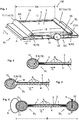
- a strip aerator 1 is shown, which is received on a holding element 2 which, according to this embodiment, is designed as a holding plate 2a.
- the aerator arrangement 100 comprising strip aerator 1 and holding plate 2a can be fastened to a floor or a wall of a clarifier or aerator basin, for example, by means of connecting means engaging the holding plate 2a or a framework (not shown).
- the strip aerator 1 has an upper film section 3 and a lower film section 4, which are connected to one another in a gas-tight manner on their longitudinal sides SL, so that a gas-carrying chamber 5 is formed between them. If the strip ventilator 1 is not in operation, that is, if gas is not actively flowing through it, the two film sections 3, 4 are at least regionally flat on top of one another or on top of one another.
- the upper film section 3 has several openings 6, for example slot-shaped holes, which can be introduced by perforating, punching, punching, drilling, lasers, water jets, etc. and which enable gas to pass from the air-conducting chamber 5 into the environment U .
- the lower film section 4 can also have such holes 6.
- the film sections 3, 4 consist of a soft or elastically deformable material, preferably plastic. Depending on the design, both film sections 3, 4 can be made from the same or from different materials which have the same or different degrees of hardness.
- the longitudinal connection between the film sections 3, 4 can be designed differently. It can thus be provided that, after their production, the two film sections 3, 4 are connected to one another in a gas-tight manner in a lateral connecting area 7 by means of gluing, welding, injection molding or extrusion.
- the openings 6 can be made in the upper film section 3 before the connection or only afterwards.
- the two film sections 3, 4 it is possible for the two film sections 3, 4 to be formed in one piece or in one piece, for example in the form of an extruded, elastically deformable hose with a correspondingly thin wall thickness, which outside of the operation of the strip ventilator 1 ′′ in itself "collapses", so that the film sections 3, 4 lie flat on top of one another or at least one on top of the other, at least in some areas.
- the strip aerator 1 has first fastening means 8, 9 on both sides in the area of the longitudinal sides SL in a receiving area 15, which serve to divert the tensile load acting on the strip aerator 1 during operation into the holding plate 2a.
- the first fastening means 8, 9 are arranged either continuously or distributed in sections in the receiving areas 15 on both longitudinal sides SL, preferably over the entire length A of the strip aerator 1.
- the Strip aerator 1 is additionally or alternatively attached to the end face, ie on one or both sides in the area of its end faces SS, to the holding plate 2a in this way, in order to divert the tensile load that acts into the holding plate 2a and to supplement the strip aerator 1 additionally or alternatively to the end face, ie in the transverse direction Q, to tension.
- the length A of the strip aerator 1 is preferably at least 0.5 m, preferably at least 2 m.
- the first fastening means 8, 9 arranged on both sides are part of the strip aerator 1 itself, the first fastening means 8, 9 being in the form of a band or rod or in the form of a welt 10 and being extended over the entire length A of the strip aerator 1.
- the respective first fastening means 8, 9 can, for example, be extruded, glued, flanged, etc. along the length of the film sections 3, 4 in the receiving area 15.
- First fastening means 8, 9 designed in this way enable the strip aerator 1 to be held in a form-fitting manner laterally by second fastening means 11, 12, the second fastening means 11, 12 in this embodiment being designed as fastening rails 11a, 12a in the manner of a welt profile 13.
- the fastening rails 11a, 12a are attached to the holding plate 2a, preferably as an integral part of the holding plate 2a.
- a rail spacing SA between the fastening rails 11a, 12a is selected such that the film sections 3, 4 run between the fastening rails 11a, 12a outside of the operation of the strip ventilator 1 with or without tensile stress.
- a width B of the strip aerator 1 is thus slightly larger or smaller than the rail spacing SA, the width B of the strip aerator 1 being between 100 mm and 250 mm, for example.
- the film sections 3, 4 may lie on an intermediate area 14 between the fastening rails 11a, 12a on the holding plate 2a. When the strip aerator 1 is in operation, at least the upper film section 3 or the membrane lifts off the intermediate region 14 of the holding plate 2a.
- first fastening means 8, 9 which are of correspondingly complementary design, can also be provided with a comparable effect in cross-section, rectangular, rectangular, semicircular, etc. , for example with a C-profile, are positively received in order to hold the strip aerator 1 on both sides.
- the first fastening means 8, 9 can also be held on the strip ventilator 1 in that one or both film sections 3, 4 in the receiving area 15 on the longitudinal sides SL, preferably over the entire length A of the strip ventilator 1, are folded over in a loop-like manner.
- the first fastening means 8, 9, in particular the welt 10, is then positioned in the loop formed thereby or enclosed by it.
- the receiving area 15 is in Fig. 2 separated from the gas-carrying chamber 5.
- the first fastening means 8, 9 it is also possible for the first fastening means 8, 9 to be extruded or clipped on, etc. in the receiving area 15 on the longitudinal sides SL, preferably over the entire length A of the strip ventilator 1 (not shown).
- both film sections 3, 4 are made in one piece or in one piece, according to FIG Fig. 3 it can be provided that the receiving area 15 is connected to the gas-carrying chamber 5 via a constriction 16.
- the respectively selected first fastening means 8, 9, for example the piping 10, is then to be inserted accordingly into the loop-like receiving area 15 and is held therein via the constriction 16 and / or a material connection.
- the respectively selected first fastening means 8, 9 can be received in a form-fitting manner in the respectively assigned fastening rail 11a, 12a in order to hold the strip aerator 1.
- the first fastening means 8, 9, in particular as a welt 10 are designed in such a way that they are received with appropriate play in the respective fastening rail 11a, 12a in order to enable them to be displaced in the longitudinal direction L.
- a fastening rail 11a, 12a is arranged as the first fastening means 8, 9 on both sides of the strip ventilator 1 in the receiving area 15, for example attached, glued, welded, extruded, flanged, etc. to the holding plate 2a tape-shaped or rod-shaped second fastening means 11, 12, for example in the form of welts 10, are fastened in such a way that the strip aerator 1 in the longitudinal direction L with the two-sided Fastening rails 11a, 12a can be pushed onto the welt 10 in order to form the form-fitting connection.
- the fastening means 8, 9 would therefore be compared to the in Fig. 1 shown embodiment with the fastening means 11, 12 interchanged.
- the strip aerator 1 can in principle also be held on both sides of the holding plate 2a via a differently designed receiving area 15. If the gas-carrying chamber 5 is in any way separated from the receiving area 15 in a gas-tight manner, the receiving area 15 can, for example, be pierced in sections by receiving holes 17 with or without protective eyelets. In an embodiment not claimed, for example, hooks, rings, straps, screws, nails, rivets, or the like can be inserted or introduced into the receiving holes 17 as first fastening means 8, 9. Since the receiving area 15 is separated from the gas-carrying chamber 5 in this embodiment, the tightness of the gas-carrying chamber 5 is not impaired.
- the rings, bands or hooks (s. Fig. 4 left) as the first fastening means 8, 9 can be permanently or detachably received in the receiving holes 17 and also permanently or detachably attached to the holding plate 2a in any manner.
- the receiving area 15 can consist of screws, nails or rivets (cf. Fig. 4 right) are pierced as the first fastening means 8, 9, so that receiving holes 17 are only formed in them afterwards when they are introduced. The screws, nails or rivets are then likewise screwed or otherwise received in the holding plate 2a.
- suitably designed first fastening means 8, 9 can also be otherwise fixed to the peripheral receiving areas 15 of the strip ventilator 1, for example clamped on from the outside, glued or welded without impairing the tightness of the gas-carrying chamber 5.
- straps or ropes 2b tensioned in the clarifier can also be provided as holding element 2.
- these can hold the first fastening means 8, 9 received or fixed to both sides in the receiving area 15 so that the gas-tight connected film sections 3, 4 can be held in their position between the straps or ropes 2b. This means that there is no longer any intermediate area 14 supporting the film sections 3, 4, although this is not necessary in any case in the structure of the strip aerator 1 according to the invention.
- the straps or ropes 2b run as holding elements 2 through the receiving area 15 and / or are attached to it in a frictional or non-positive and / or cohesive manner, so that the strip aerator 1 by pulling the ropes 2b out of the clarifier removed or immersed in it.
- a first fastening means 8, 9 for connecting the strip ventilator 1 to the holding element 2 is not absolutely necessary or this is achieved via the non-positive and / or material connection.
- the film sections 3, 4 are also connected to one another in a gas-tight manner at their end faces SS.
- This end-side connection can be made in a manner comparable to the connection on the longitudinal sides SL by means of gluing or welding or injection molding and / or via an additional closing profile 18 as a closure element, which, as in FIG Fig. 6 shown can be added in a shaping process, for example in a plastic or rubber press, and which encloses the two film sections 3, 4 between them in a gas-tight manner.
- This closing profile 18 can also be produced with a comparable effect by gluing, lasering, tensioning, welding or screwing two strips or a clamp.
- one or both end faces SS of the film sections 3, 4 or of the strip ventilator 1 can be closed in a gas-tight manner.
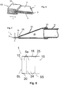
- the strip aerator 1 according to FIG Fig. 7 on one of the end faces SS at least one through opening 19 with a connection channel 20 for receiving, for example, a pipe 21 (inlet channel).
- the through opening 19 with the connection channel 20 can basically be in the upper film section 3 (not shown), in the lower film section 4 (not shown) or as in FIG Fig. 7 be provided on the end face shown. It can also be provided that the pipe 21 is glued, welded, directly to the film sections 3, 4 forming a gas-tight connection, clamp, etc.
- the pipe 21 as the inlet channel thus replaces the connection channel 20.
- an end connection channel 20 provision can be made, for example, to insert the laterally gas-tight and end-face (on one or both sides) still open film sections 3, 4 into a plastic or rubber press and to attach a widening opening 22 via a molding tool with a core to the end face with a through opening 19 provided film sections 3, 4 in a shaping process.
- the material of the connecting channel 20 added in the shaping process is preferably the same or a comparable material as that of the film sections 3, 4, but can also consist of a different material.
- the pipe 21 can then be inserted into the connection channel 20 and, for example, fastened by means of clamps 23, so that a gas supply can take place via the pipe 21 as an inlet channel.
- Such an end connection channel 20 can also be provided on both end faces SS of the film sections 3, 4 in order to be able to form, for example, an aerator chain from a plurality of such strip aerators 1.
- an end connection channel 20 can also be combined with a connection channel 20 on the upper and / or lower film section 3, 4 in order to build up an aerator chain.
- a plurality of gas-carrying sub-chambers 5a can be formed between two film sections 3, 4.
- This can be done according to Fig. 8 can be achieved, for example, in that the gas-carrying chamber 5 formed between the film sections 3, 4 is subdivided by intermediate connections 24 running in the longitudinal direction L and / or in the transverse direction Q.
- the trained thereby Several sub-chambers 5a can be exposed to gas from the outside via separate connection channels 20 and / or by the fact that the intermediate connections 24 are cut out in some areas, so that passage channels 25 are formed between the individual sub-chambers 5a.
- gas can be applied to all sub-chambers 5a via just one connection channel 20 or, depending on the area of the subdivided strip ventilator 1, also via further connection channels 20.
- the intermediate area 14 in the execution according to Fig. 1 is only due to the flat shape of the holding plate 2a, the function of the strip aerator 1 being completely independent of the supporting effect of the holding plate 2a and any other support bodies.
- the strip aerator 1 can therefore be designed to be flat and with little buoyancy (and thus optimized in terms of efficiency) without a carrier system.
- the dismantled strip aerator 1 can be wound up in a space-saving manner, for example, due to its elastic resilience in the longitudinal direction L, and can thus be transported and stored more easily.
Description
Die vorliegende Erfindung betrifft eine Belüfteranordnung mit mindestens einem Streifenbelüfter zur Belüftung und Begasung von Flüssigkeiten.The present invention relates to an aerator arrangement with at least one strip aerator for aeration and gassing of liquids.
Derartige Streifenbelüfter oder auch Flächenbelüfter dienen insbesondere zur Belüftung und Begasung von Abwasser als Flüssigkeit, wobei eine flächig ausgebildete Membran mit einer Perforierung oder einer Lochung zum Ausbilden einer Vielzahl an Öffnungen vorgesehen ist. Durch diese Öffnungen kann Gas aus einer gasführenden Kammer des Streifenbelüfters entweichen, um die Flüssigkeit bzw. das Abwasser entsprechend zu behandeln.Such strip aerators or surface aerators are used in particular for aeration and gassing of wastewater as a liquid, a flat membrane with a perforation or a perforation for forming a large number of openings being provided. Gas can escape through these openings from a gas-carrying chamber of the strip aerator in order to treat the liquid or the waste water accordingly.
Ein derartiger Streifenbelüfter ist beispielsweise aus der
Ein derartiger Aufbau hat zur Folge, dass zwischen dem Hohlprofilkörper bzw. der Tragwand und der Membran seitlich aufwendige Dichtprofile einzusetzen sind und auch stirnseitig ein Abdichten der Membran mit aufwendigen Systemen zu erfolgen hat. Teilweise ist auf Dicht- und Klebstoffe zurückzugreifen, um das System dauerhaft abzudichten. Die Herstellung eines solchen Streifenbelüfters mit einer Tragwand zum Abstützen der perforierten bzw. gelöcherten Membran ist daher sehr aufwändig. Damit ist auch ein Austausch der Membran z.B. im Rahmen einer Wartung mit sehr hohem Aufwand verbunden.Such a structure has the consequence that laterally complex between the hollow profile body or the supporting wall and the membrane Sealing profiles are to be used and the membrane has to be sealed with complex systems on the front side. In some cases, sealants and adhesives have to be used to permanently seal the system. The production of such a strip aerator with a supporting wall for supporting the perforated or perforated membrane is therefore very complex. This means that replacement of the membrane, for example in the context of maintenance, is very costly.
Das Halten eines solchen Streifenbelüfters beispielsweise am Klärbeckenboden kann gemäß
Damit ist die Halteplatte als Halteelement gezielt an den jeweiligen starr ausgeführten Hohlprofilkörper des Streifenbelüfters anzupassen, so dass jeder Streifenbelüfter eine individuell gefertigte Halterung benötigt.In this way, the holding plate as a holding element can be specifically adapted to the respective rigidly designed hollow profile body of the strip aerator, so that each strip aerator requires an individually manufactured holder.
Weitere Belüfteranordnungen mit Streifenbelüftern mit einem Stützkörper sind beispielsweise in
Aufgabe der vorliegenden Erfindung ist daher, eine Belüfteranordnung bereitzustellen, die trotz einer einfachen Fertigung einen zuverlässigen Betrieb ermöglicht und dabei flexibel eingesetzt werden kann.The object of the present invention is therefore to provide an aerator arrangement which, despite being simple to manufacture, enables reliable operation and can be used flexibly.
Diese Aufgabe wird erfindungsgemäß mit einer Belüfteranordnung gemäß dem unabhängigen Anspruch gelöst. Die Unteransprüche beschreiben bevorzugte Weiterbildungen.This object is achieved according to the invention with an aerator arrangement according to the independent claim. The subclaims describe preferred developments.
Erfindungsgemäß ist demnach vorgesehen, dass die mindestens eine gasführende Kammer des Streifenbelüfters nach unten hin durch mindestens einen weichen bzw. elastisch verformbaren unteren Folienabschnitt vorzugsweise vollflächig begrenzt ist, wobei der mindestens eine untere Folienabschnitt mit mindestens einem ebenfalls weichen bzw. elastisch verformbaren oberen Folienabschnitt gasdicht verbunden ist, so dass durch die oberen und unteren Folienabschnitte ein gasdicht abgeschlossener elastisch verformbarer Körper mit einer gasführenden Kammer in seinem Inneren ausgebildet wird, und die gasdicht verbundenen Folienabschnitte zwischen seitlichen Aufnahmebereichen, die an gegenüberliegenden Seiten des Streifenbelüfters angeordnet sind, zumindest bereichsweise, vorzugsweise vollflächig, flächig aufeinander und/oder übereinander liegen.According to the invention it is therefore provided that the at least one gas-carrying chamber of the strip ventilator is delimited towards the bottom by at least one soft or elastically deformable lower film section, preferably over the entire surface, the at least one lower film section being connected in a gastight manner to at least one likewise soft or elastically deformable upper film section is, so that a gas-tight closed, elastically deformable body with a gas-carrying chamber in its interior is formed by the upper and lower film sections, and the gas-tight connected film sections between lateral receiving areas which are arranged on opposite sides of the strip ventilator, at least in some areas, preferably over the entire area, lie flat on top of each other and / or on top of each other.
Die Folienabschnitte sind dabei beispielsweise aus elastischem Kunststoff gefertigt und können aus demselben oder aus unterschiedlichen Materialen mit denselben oder mit unterschiedlichen Härtegraden bestehen.The film sections are made, for example, of elastic plastic and can consist of the same or different materials with the same or different degrees of hardness.
Damit wird ein Streifenbelüfter des Standes der Technik derartig weitergebildet, dass dieser unabhängig von einem nicht-elastischen tragenden Grundkörper bzw. Stützkörper ist, der sich wie im Stand der Technik als Bestandteil des Streifenbelüfters in der gasführenden Kammer befindet bzw. diese mit begrenzt und auf denen die Folienabschnitte im oder außerhalb des Betriebes des Streifenbelüfters aufliegen können. Demnach ist der oberen Folienabschnitt als Membran vorteilhafterweise nicht aufwändig gegenüber einem tragenden Grundkörper abzudichten, z.B. über Dichtprofile, so dass die Abdichtung des Gesamtsystems vereinfacht wird.A strip aerator of the prior art is thus developed in such a way that it is independent of a non-elastic load-bearing base body or support body which, as in the prior art, is located as part of the strip aerator in the gas-carrying chamber or delimits it and on which the film sections can rest inside or outside of the operation of the strip aerator. Accordingly, the upper film section as a membrane does not need to be sealed against a load-bearing base body, e.g. using sealing profiles, so that the sealing of the overall system is simplified.
Die Abdichtung ist damit auch robuster ausgeführt, da die Folienabschnitte bereits bei der Montage miteinander gasdicht verbunden und zu einem elastisch verformbaren Körper zusammengefügt sind und nicht erst bei der Montage des Streifenbelüfters z.B. über die Dichtprofile miteinander zu verbinden sind. Die Montage wird dadurch insgesamt vereinfacht, wobei über die seitlichen Aufnahmebereiche eine Befestigung auf unterschiedlichen Tragsystemen bzw. Halteelementen erfolgen kann. Dadurch wird die Flexibilität erhöht, da die Befestigung nicht mehr abhängig von einem die Membran flächig tragenden bzw. flächig abstützenden Grundkörper ist, der zudem die Membran im Betrieb gegen den Auftrieb in ihrer Position hält. Insgesamt muss der Streifenbelüfter nicht mehr zwangsläufig flächig auf einem Grundkörper aufliegen. Es ist lediglich für einen ausreichenden seitlichen Halt bzw. ein Abspannen des durch die beiden Folienabschnitte ausgebildeten elastisch verformbaren Körpers zu sorgen, um den Streifenbelüfter gegen den Auftrieb in seiner Position zu halten, wenn dieser im Betrieb mit Gas beaufschlagt wird.The seal is therefore also more robust, since the film sections are already connected to one another in a gas-tight manner during assembly and are joined together to form an elastically deformable body and do not have to be connected to one another e.g. via the sealing profiles during assembly of the strip ventilator. The assembly is thereby simplified overall, it being possible for fastening to different support systems or holding elements to take place via the lateral receiving areas. This increases the flexibility, since the fastening is no longer dependent on a base body which carries or supports the membrane over a large area and which also holds the membrane in its position during operation against the buoyancy. Overall, the strip aerator no longer necessarily has to lie flat on a base body. It is only necessary to ensure sufficient lateral support or tensioning of the elastically deformable body formed by the two film sections in order to hold the strip aerator in its position against the buoyancy when it is acted upon with gas during operation.
Auch der Austausch der Membran wird vereinfacht, da der komplette Streifenbelüfter bei Defekten oder im Rahmen einer Wartung vom Halteelement einfach entfernt und komplett ausgetauscht bzw. gereinigt werden kann, ohne diesen nachfolgend gegenüber einem tragenden Grundköper bzw. dem Halteelement abdichten zu müssen. Somit ist allenfalls ein tragendes Halteelement vorhanden, das jedoch nicht aufwändig abzudichten ist.The replacement of the membrane is also simplified, since the complete strip ventilator can simply be removed from the retaining element and completely replaced or cleaned in the event of defects or during maintenance, without having to subsequently seal it against a supporting base body or the retaining element. Thus, at most, there is a load-bearing holding element which, however, does not need to be sealed in a complex manner.
Die Ausführung als eigenständig belüfteter elastisch verformbarer Körper, der durch die beiden Folienabschnitte ausgebildet wird, kann in einfacher Weise in nahezu beliebige Trägersysteme integriert werden. Der Streifenbelüfter mit der Membran kann sehr schnell aus einem Haltelement entfernt werden, um den Streifenbelüfter mit der Membrane zu tauschen, dabei können Trägersysteme bzw. Halteelemente auf dem Boden montiert verbleiben. Die Funktion der Membrane bzw. der Folienabschnitte ist damit unabhängig vom jeweiligen Halteelement bzw. Tragsystem. Damit können einfachste Halteelemente verwendet werden, auf denen der Streifenbelüfter befestigt wird bzw. von denen dieser gehalten wird. Diese Halteelemente können sehr flach und auftriebsarm ausgeführt werden und somit wirkungsgradoptimiert arbeiten.The design as an independently ventilated, elastically deformable body, which is formed by the two film sections, can be easily integrated into almost any carrier system. The strip aerator with the membrane can be removed very quickly from a holding element in order to exchange the strip aerator with the membrane, while the carrier systems or holding elements can remain mounted on the floor. The function of the membrane or the film sections is therefore independent of the respective holding element or support system. This means that the simplest holding elements can be used on which the strip aerator is attached or by which it is held. These holding elements can be made very flat and with little buoyancy and thus work in an optimized manner.
Zudem kann der Streifenbelüfter aufgrund der elastisch verformbar ausgeführten Folienabschnitte platzsparend gelagert und transportiert werden, beispielsweise aufgewickelt auf einer Rolle. Der Streifenbelüfter kann also ohne Halteelement bzw. das jeweilige Tragsystem transportiert werden, da er unabhängig von diesen ist. Die Installation des Streifenbelüfters kann nach der Montage der Halteelemente erfolgen.In addition, because of the elastically deformable film sections, the strip aerator can be stored and transported in a space-saving manner, for example wound up on a roll. The strip aerator can therefore be transported without a holding element or the respective support system, since it is independent of these. The strip aerator can be installed after the retaining elements have been installed.
Als gattungsgemäßer Streifenbelüfter wird dabei ein flächiger Belüfter angenommen, der mindestens eine Durchgangsöffnung mit einem Anschlusskanal für den Durchtritt eines Gases aus einem Einlasskanal in mindestens eine, durch den mindestens einen oberen Folienabschnitt nach oben hin begrenzte, gasführende Kammer aufweist, aus der das Gas durch die flächige Membran in eine Umgebung austreten kann. Der Streifenbelüfter weist dabei zumindest an gegenüberliegenden Seiten, d.h. seitlich vorzugsweise zumindest an den beiden Längsseiten und/oder auch an der oder den Stirnseiten, in Längsrichtung bzw. in Querrichtung ausgedehnte bzw. verlaufende Aufnahmebereiche auf, um den Streifenbelüfter durchgängig oder abschnittsweise an mindestens ein Halteelement anbinden und den Streifenbelüfter dadurch abspannen zu können. Aufgrund der elastischen Verformbarkeit liegt der obere Folienabschnitt ohne Beaufschlagung des Streifenbelüfters bzw. der gasführenden Kammer mit einem Gas auf dem unteren Folienabschnitt flächig auf, fällt also nach unten bzw. in sich zusammen. Bei einer Beaufschlagung hebt der obere Folienabschnitt mit den die Membran bildenden Öffnungen von dem unteren Folienabschnitt ab.A flat aerator is assumed as the generic strip aerator, which has at least one passage opening with a connection channel for the passage of a gas from an inlet channel into has at least one gas-carrying chamber, delimited towards the top by the at least one upper film section, from which the gas can escape through the flat membrane into an environment. The strip aerator has at least on opposite sides, ie laterally, preferably at least on the two longitudinal sides and / or also on the end face or sides, in the longitudinal direction or in the transverse direction extending or extending receiving areas, around the strip aerator continuously or in sections on at least one holding element to be able to tie up the strip aerator. Due to the elastic deformability, the upper film section rests flat on the lower film section without exposure of the strip ventilator or the gas-carrying chamber with a gas, that is to say it collapses downwards or collapses on itself. In the event of an impact, the upper film section with the openings forming the membrane lifts off from the lower film section.
Vorzugsweise kann dabei vorgesehen sein, dass der mindestens eine obere Folienabschnitt und der mindestens eine untere Folienabschnitt einteilig bzw. einstückig ausgebildet sind, d.h. frei von sichtbaren oder unsichtbaren Fügestellen ineinander übergehen, wobei die Folienabschnitte seitlich (längsseitig und/oder stirnseitig) an den Aufnahmebereichen ineinander übergehen. Alternativ kann auch eine zweiteilige Ausführung vorgesehen sein, bei der die Folienabschnitte seitlich bzw. an den Längsseiten und/oder an den Stirnseiten formschlüssig und/oder kraftschlüssig zusammengefügt sind.It can preferably be provided that the at least one upper film section and the at least one lower film section are formed in one piece or in one piece, i.e. merge into one another free of visible or invisible joints, with the film sections laterally (longitudinally and / or frontally) into one another at the receiving areas pass over. Alternatively, a two-part design can also be provided in which the film sections are joined together laterally or on the longitudinal sides and / or on the front sides in a form-fitting and / or force-fitting manner.
Damit ist ein variabler Aufbau bzw. eine variable Herstellung des Streifenbelüfters möglich, wobei bei der einteiligen Ausführung, z.B. als Schlauch, keine zusätzliche Abdichtung an den Längsseiten bzw. Stirnseiten nötig ist. Bei der zweiteiligen Ausführung ist vorzugsweise vorgesehen, dass die Folienabschnitte durch Kleben, Schweißen, Spritzgießen oder Extrudieren in einem Verbindungsbereich seitlich (stirnseitig und/oder längsseitig) zusammengefügt sind. Die stirnseitige (und grundsätzlich auch die längsseitige) gasdichte Abdichtung kann aber vorzugsweise auch durch ein Abschlussprofil oder eine Schelle erfolgen, die die Folienabschnitte jeweils stirnseitig (bzw. längsseitig) gasdicht zusammenhalten können.A variable construction or a variable production of the strip aerator is thus possible, with the one-piece design, for example as a hose, not requiring any additional sealing on the long sides or front sides. In the two-part design, it is preferably provided that the film sections by gluing, welding, injection molding or Extruding in a connection area laterally (front side and / or longitudinal side) are joined together. The front (and in principle also the longitudinal) gas-tight seal can, however, preferably also take place by means of an end profile or a clip, which can hold the film sections together gas-tight at the front (or longitudinal side).
Zum Anbinden des Streifenbelüfters an ein Halteelement ist erfindungsgemäß zumindest einer der Folienabschnitte mit ersten Befestigungsmitteln verbunden, wobei die ersten Befestigungsmittel im Aufnahmebereich abschnittsweise oder durchgängig in Längsrichtung und/oder in Querrichtung, je nach Anbindungsart, verlaufen. Dadurch kann im Betrieb des Streifenbelüfters ein sicherer Halt gewährleistet werden, wobei zur einfachen Montage erfindungsgemäß vorgesehen ist, dass die ersten Befestigungsmittel
- stabförmig oder bandförmig ausgeführt sind, z.B. mit einem runden oder ovalen oder rechteckigen oder quadratischen oder jedem beliebigen anderen Querschnitt, insbesondere in Form eines Keders, oder als
- Befestigungsschienen, insbesondere in Form eines C-Profils oder eines Keder-Profils. Dadurch können diese bei entsprechend eingestelltem Spiel in Längsrichtung bzw. Querrichtung ineinandergeschoben werden, um eine formschlüssige Verbindung auszubilden, und damit einfach montiert bzw. demontiert werden. Weiterhin können gemäß einer nicht beanspruchten Ausführungsform als erste Befestigungsmittel aber auch Haken, Bänder, Ringe, Schrauben, Nägel oder Nieten oder gleichwirkende Mittel verwendet werden.
- Are rod-shaped or ribbon-shaped, for example with a round or oval or rectangular or square or any other cross-section, in particular in the form of a welt, or as
- Fastening rails, in particular in the form of a C-profile or a piping profile. As a result, with the play set accordingly, they can be pushed into one another in the longitudinal or transverse direction in order to form a form-fitting connection, and can thus be easily assembled or disassembled. Furthermore, according to an embodiment not claimed, hooks, straps, rings, screws, nails or rivets or means having the same effect can also be used as the first fastening means.
Zum Halten der ersten Befestigungsmittel kann vorgesehen sein, dass diese an die seitlichen Aufnahmebereiche anextrudiert, angeklebt, angeflanscht sind, oder zumindest einer der Folienabschnitte randseitig derartig schlaufenartig verformt, z.B. umgeschlagen oder eingeengt ist, dass sich ein Aufnahmebereich ausbildet, der das erste Befestigungsmittel zumindest teilweise umschließt und dadurch festhält. Damit kann eine variable Befestigungsmöglichkeit geschaffen werden.To hold the first fastening means, it can be provided that they are extruded, glued, flanged onto the lateral receiving areas, or at least one of the film sections is deformed like a loop at the edge, e.g. turned over or narrowed, so that a receiving area is formed which the first fastening means at least partially encloses and thereby holds in place. A variable fastening option can thus be created.
Vorzugsweise kann weiterhin vorgesehen sein, dass in dem mindestens einen oberen Folienabschnitt und/oder in dem mindestens einen unteren Folienabschnitt und/oder zumindest an einer Stirnseite zwischen dem mindestens einen oberen Folienabschnitt und dem mindestens einen unteren Folienabschnitt eine Durchgangsöffnung angeordnet ist, die mit dem Einlasskanal, beispielsweise einem Rohr, vorzugsweise über einen Anschlusskanal, verbunden ist, wobei der Anschlusskanal und/oder der Einlasskanal im Bereich der Durchgangsöffnung mit mindestens einem der Folienabschnitte formschlüssig und/oder kraftschlüssig verbunden ist, beispielsweise geklebt, geschweißt, geklemmt oder in einem formgebenden Prozess angefügt. Dadurch kann in einfacher und flexibler Weise eine Beaufschlagung der gasführenden Kammer mit Gas bewirkt werden.It can preferably also be provided that a through opening is arranged in the at least one upper film section and / or in the at least one lower film section and / or at least on one end face between the at least one upper film section and the at least one lower film section, which is connected to the inlet channel , for example a pipe, preferably via a connection channel, the connection channel and / or the inlet channel being positively and / or non-positively connected to at least one of the film sections in the area of the passage opening, for example glued, welded, clamped or attached in a shaping process . As a result, the gas-carrying chamber can be charged with gas in a simple and flexible manner.
Um die Fläche des Streifenbelüfters zu vergrößern, kann ergänzend vorgesehen sein, dass die zwischen den Folienabschnitten ausgebildete gasführende Kammer durch in Längsrichtung und/oder in eine Querrichtung verlaufende Zwischenverbindungen in Teilkammern unterteilt ist. Damit kann ein Streifenbelüfter, dessen gasführende Kammer normalerweise eine Länge von mindestens 50cm, vorzugsweise mindestens 200cm, und eine Breite von zwischen 100mm und 250mm aufweist, länger oder breiter ausgeführt werden, indem mehrere solcher Kammern in Reihe oder parallel hintereinander und/oder nebeneinander "geschaltet" werden.In order to enlarge the area of the strip ventilator, it can additionally be provided that the gas-carrying chamber formed between the film sections is divided into sub-chambers by intermediate connections running in the longitudinal direction and / or in a transverse direction. A strip aerator, the gas-carrying chamber of which is normally at least 50cm, preferably at least 200cm, and a width of between 100mm and 250mm, can be made longer or wider by connecting several such chambers in series or in parallel one behind the other and / or next to one another " will.
Weiterhin ist eine Belüfteranordnung mit einem erfindungsgemäßen Streifenbelüfter sowie einem Halteelement vorgesehen, wobei der Streifenbelüfter über die zumindest an den gegenüberliegenden Seiten in Längsrichtung und/oder in Querrichtung ausgedehnten bzw. verlaufenden Aufnahmebereiche durchgängig oder abschnittsweise an den Halteelementen angebunden ist, so dass die gasdicht verbundenen Folienabschnitte des Streifenbelüfters zwischen den Aufnahmebereichen zumindest bereichsweise flächig aufeinander und/oder übereinander liegen.Furthermore, an aerator arrangement with a strip aerator according to the invention and a holding element is provided, the strip aerator extending or extending over the receiving areas which are extended or extending at least on the opposite sides in the longitudinal direction and / or in the transverse direction is connected continuously or in sections to the holding elements, so that the gas-tight connected film sections of the strip ventilator between the receiving areas are at least partially flat on top of one another and / or one above the other.
Der Streifenbelüfter ist dabei erfindungsgemäß je nach Befestigungsart bzw. Befestigungsmittel verschieblich in dem Halteelement aufgenommen.According to the invention, the strip aerator is accommodated in the holding element so as to be displaceable, depending on the type of fastening or fastening means.
Die Erfindung wird nachstehend anhand von Ausführungsbeispielen näher erläutert. Es zeigen:
- Fig. 1
- eine perspektivische Ansicht einer Belüfteranordnung mit einem Streifenbelüfter;
- Fig. 2, 3, 4
- eine Schnittansicht durch einen Aufnahmebereich des Strei-fenbelüfters in unterschiedlichen Ausführungen;
- Fig. 5a, 5b
- weitere Ausführungen zum Halten des Streifenbelüfters;
- Fig. 6, 7
- stirnseitige Ausführungen des Streifenbelüfters; und
- Fig. 8
- der Streifenbelüfter in einer weiteren Ausführungsform.
- Fig. 1
- a perspective view of an aerator assembly with a strip aerator;
- Figures 2, 3, 4
- a sectional view through a receiving area of the strip aerator in different designs;
- Figures 5a, 5b
- further explanations for holding the strip aerator;
- Fig. 6, 7
- frontal versions of the strip aerator; and
- Fig. 8
- the strip aerator in a further embodiment.
In
Gemäß der Detailansicht in
Der obere Folienabschnitt 3 weist mehrere Öffnungen 6, z.B. schlitzförmige Löcher, auf, die durch Perforieren, Lochen, Stanzen, Bohren, Lasern, Wasserstrahlen, etc. eingebracht werden können und die einen Durchtritt von Gas aus der luftführenden Kammer 5 in die Umgebung U ermöglicht. Grundsätzlich kann auch der untere Folienabschnitt 4 derartige Löcher 6 aufweisen.The
Die Folienabschnitte 3, 4 bestehen aus einem weichen bzw. elastisch verformbaren Material, vorzugsweise Kunststoff. Je nach Ausführung können beide Folienabschnitte 3, 4 aus demselben oder aus unterschiedlichen Materialen gefertigt sein, die dieselben oder unterschiedliche Härtegrade aufweisen.The
Die längsseitige Verbindung zwischen den Folienabschnitten 3, 4 kann unterschiedlich ausgebildet sein. So kann vorgesehen sein, dass beide Folienabschnitte 3, 4 nach deren Herstellung mittels Kleben, Schweißen, Spritzgießen oder Extrudieren in einem seitlichen Verbindungsbereich 7 miteinander gasdicht verbunden werden. Das Einbringen der Öffnungen 6 in den oberen Folienabschnitt 3 kann dabei vor dem Verbinden erfolgen oder erst nachträglich. Weiterhin ist es möglich, dass die beiden Folienabschnitte 3, 4 einstückig bzw. einteilig ausgebildet sind, beispielsweise in Form eines extrudierten, elastisch verformbaren Schlauches mit entsprechend dünner Wandstärke, der außerhalb des Betriebes des Streifenbelüfters 1 "in sich zusammenfällt", so dass die Folienabschnitte 3, 4 zumindest bereichsweise flächig aufeinander oder zumindest übereinander liegen.The longitudinal connection between the
Zum Anbinden des Streifenbelüfters 1 an die Halteplatte 2a weist der Streifenbelüfter 1 beidseitig im Bereich der Längsseiten SL in einem Aufnahmebereich 15 erste Befestigungsmittel 8, 9 auf, die dazu dienen, die im Betrieb auf den Streifenbelüfter 1 wirkende Zugbelastung in die Halteplatte 2a abzuleiten. Um ein gleichmäßiges Ableiten in die Halteplatte 2a zu ermöglichen, sind die ersten Befestigungsmittel 8, 9 entweder durchgängig oder abschnittsweise verteilt in den Aufnahmebereichen 15 auf beiden Längsseiten SL angeordnet, vorzugsweise über die gesamte Länge A des Streifenbelüfters 1. Grundsätzlich besteht die Möglichkeit, dass der Streifenbelüfter 1 in dieser Weise ergänzend oder alternativ stirnseitig, d.h. einseitig oder beidseitig im Bereich seiner Stirnseiten SS, an der Halteplatte 2a angebunden ist, um die wirkende Zugbelastung in die Halteplatte 2a abzuleiten und den Streifenbelüfter 1 ergänzend oder alternativ stirnseitig, d.h. in Querrichtung Q, zu spannen. Die Länge A des Streifenbelüfters 1 beträgt dabei vorzugsweise mindestes 0,5m, vorzugsweise mindestens 2m.To connect the
Gemäß der Ausführungsform in
Ein Schienen-Abstand SA zwischen den Befestigungsschienen 11a, 12a ist dabei derartig gewählt, dass die Folienabschnitte 3, 4 außerhalb des Betriebes des Streifenbelüfters 1 ohne, oder mit Zugspannung zwischen den Befestigungsschienen 11a, 12a verlaufen. Eine Breite B des Streifenbelüfters 1 ist damit geringfügig größer, oder kleiner als der Schienen-Abstand SA, wobei die Breite B des Streifenbelüfters 1 beispielsweise zwischen 100mm und 250mm beträgt. Die Folienabschnitte 3, 4 liegen dabei möglicherweise auf einem Zwischenbereich 14 zwischen den Befestigungsschienen 11a, 12a auf der Halteplatte 2a auf. Im Betrieb des Streifenbelüfters 1 hebt zumindest der obere Folienabschnitt 3 bzw. die Membran von dem Zwischenbereich 14 der Halteplatte 2a ab.A rail spacing SA between the
Statt den stabförmigen ersten Befestigungsmitteln 8, 9 mit einem kreisrunden Querschnitt (Keder 10) können mit vergleichbarer Wirkung auch im Querschnitt quaderförmige, ovale, rechteckige, halbrunde, etc. erste Befestigungsmittel 8, 9 vorgesehen sein, die von entsprechend komplementär ausgeführten Befestigungsschienen 11a, 12a, z.B. mit einem C-Profil, formschlüssig aufgenommen werden, um den Streifenbelüfter 1 beidseitig zu halten.Instead of the rod-shaped first fastening means 8, 9 with a circular cross-section (piping 10), first fastening means 8, 9, which are of correspondingly complementary design, can also be provided with a comparable effect in cross-section, rectangular, rectangular, semicircular, etc. , for example with a C-profile, are positively received in order to hold the
Wie in
Sind beide Folienabschnitte 3, 4 einstückig bzw. einteilig gefertigt, kann gemäß
Durch die Verwendung einer Befestigungsschiene 11a, 12a wird in diesen Ausführungsbeispielen ein nachträgliches Entfernen des Streifenbelüfters 1 von der Halteplatte 2a bzw. ein nachträgliches Montieren des Streifenbelüfters 1 an der Halteplatte 2a und damit ein Austausch in einfacher Weise ermöglicht. Die ersten Befestigungsmittel 8, 9, insbesondere als Keder 10, sind dazu derartig ausgeführt, dass diese mit entsprechendem Spiel in der jeweiligen Befestigungsschiene 11a, 12a aufgenommen sind, um eine Verschieblichkeit in die Längsrichtung L zu ermöglichen.By using a
Grundsätzlich ist es auch möglich, dass beidseitig des Streifenbelüfters 1 im Aufnahmebereich 15 als erste Befestigungsmittel 8, 9 jeweils eine Befestigungsschiene 11a, 12a angeordnet ist, beispielsweise in einem formgebenden Prozess angefügt, angeklebt, angeschweißt, anextrudiert, angeflanscht etc.. An der Halteplatte 2a sind bandförmige oder stabförmige zweite Befestigungsmittel 11, 12 z.B. in Form von Kedern 10 derartig befestigt, dass der Streifenbelüfter 1 in Längsrichtung L mit den beidseitigen Befestigungsschienen 11a, 12a auf die Keder 10 aufgeschoben werden kann, um die formschlüssige Verbindung auszubilden. Die Befestigungsmittel 8, 9 wären daher gegenüber der in
Der Streifenbelüfter 1 kann grundsätzlich auch über einen andersartig ausgeführten Aufnahmebereich 15 beidseitig an der Halteplatte 2a gehalten werden. Ist die gasführende Kammer 5 in irgendeiner Weise von dem Aufnahmebereich 15 gasdicht separiert, kann der Aufnahmebereich 15 beispielsweise abschnittsweise von Aufnahmelöchern 17 mit oder ohne schützende Ösen durchstoßen werden. In die Aufnahmelöcher 17 können als erste Befestigungsmittel 8, 9 in einer nicht beanspruchten Ausführungsform beispielsweise Haken, Ringe, Bänder, Schrauben, Nägel, Niete, o.ä. eingesteckt bzw. eingebracht werden. Da der Aufnahmebereich 15 in dieser Ausführung von der gasführenden Kammer 5 getrennt ist, wird die Dichtheit der gasführenden Kammer 5 dadurch nicht beeinträchtigt.The
Beispielsweise können die Ringe, Bänder oder Haken (s.
Grundsätzlich können geeignet ausgeführte erste Befestigungsmittel 8, 9 auch anderweitig an den randseitigen Aufnahmebereichen 15 des Streifenbelüfters 1 fixiert, beispielsweise von außen angeklemmt, geklebt oder geschweißt werden, ohne die Dichtheit der gasführenden Kammer 5 zu beeinträchtigen.In principle, suitably designed first fastening means 8, 9 can also be otherwise fixed to the peripheral receiving
Statt einer Halteplatte 2a als Halteelement 2 können mit derartigen den Aufnahmebereich 15 durchstoßenden oder an diesen anderweitig fixierten ersten Befestigungsmitteln 8, 9 gemäß
Weiterführend kann vorgesehen sein, dass die Bänder bzw. Seile 2b als Halteelemente 2 durch den Aufnahmebereich 15 verlaufen und/oder an diesem reibschlüssig bzw. kraftschlüssig und/oder stoffschlüssig befestigt sind, so dass der Streifenbelüfter 1 durch Ziehen an den Seilen 2b aus dem Klärbecken entfernt bzw. in dieses eingetaucht werden kann. In diesem Fall ist ein erstes Befestigungsmittel 8, 9 zum Anbinden des Streifenbelüfters 1 an das Halteelement 2 nicht unbedingt nötig bzw. wird dies über die kraftschlüssige und/oder stoffschlüssige Verbindung erreicht.Furthermore, it can be provided that the straps or
Zudem können statt einer flächigen Halteplatte 2a mit integrierten Befestigungsschienen 11a, 12a (s.
Diese können beispielsweise am Klärbecken oder an einem Gerüst befestigt werden und für den Halt des Streifenbelüfters 1 sorgen. Gegenüber
Um die beiden Folienabschnitte 3, 4 vollkommen gasdicht abzuschließen und damit einen Austritt des Gases aus der gasführenden Kammer 5 lediglich durch die Öffnungen 6 in dem oberen Folienabschnitt 3 zu bewirken, sind die Folienabschnitte 3, 4 an ihren Stirnseiten SS ebenfalls gasdicht miteinander verbunden. Diese stirnseitige Verbindung kann vergleichbar zur Verbindung an den Längsseiten SL mittels Kleben oder Schweißen oder Spritzgiessen erfolgen und/oder über ein zusätzliches Abschlussprofil 18 als Verschlusselement, das wie in
Auf diese Art und Weisen können also eine oder beide Stirnseiten SS der Folienabschnitte 3, 4 bzw. des Streifenbelüfters 1 gasdicht verschlossen werden.In this way, one or both end faces SS of the
Um die gasdichte Kammer 5 mit dem Gas beaufschlagen zu können, weist der Streifenbelüfter 1 gemäß
Zur Ausbildung eines stirnseitigen Anschlusskanals 20 kann beispielsweise vorgesehen sein, die seitlich gasdicht verbundenen und stirnseitig (einseitig oder beidseitig) noch offenen Folienabschnitte 3, 4 in eine Kunststoff- oder Gummipresse einzulegen und eine sich aufweitende Öffnung 22 über ein Formwerkzeug mit Kern an die stirnseitig mit einer Durchgangsöffnung 19 versehenen Folienabschnitte 3, 4 in einem formgebenden Prozess anzufügen. Das Material des im formgebenden Prozess angefügten Anschlusskanals 20 ist vorzugsweise dasselbe oder ein vergleichbares Material wie das der Folienabschnitte 3, 4, kann aber auch aus einem anderen Material bestehen. Das Rohr 21 kann anschließend in den Anschlusskanal 20 eingesteckt und z.B. mittels Schellen 23 befestigt werden, so dass über das Rohr 21 als Einlasskanal eine Gaszuführung erfolgen kann.To form an
Ein derartiger stirnseitiger Anschlusskanal 20 kann auch an beiden Stirnseiten SS der Folienabschnitte 3, 4 vorgesehen sein, um beispielsweise eine Belüfterkette aus mehreren derartigen Streifenbelüfter 1 ausbilden zu können. Es kann aber auch ein stirnseitiger Anschlusskanal 20 mit einem Anschlusskanal 20 am oberen und/oder unteren Folienabschnitt 3, 4 kombiniert werden, um damit eine Belüfterkette aufzubauen.Such an
Alternativ oder ergänzend kann zum Belüften einer größeren Fläche vorgesehen sein, dass zwischen zwei Folienabschnitten 3, 4 mehrere gasführende Teilkammern 5a ausgebildet werden. Dies kann gemäß
Damit wird erfindungsgemäß ein Streifenbelüfter 1 bereitgestellt, der aufweist:
- die mindestens zwei gasdicht miteinander verbundenen Folienabschnitte 3, 4 zum Ausbilden der gasführenden
Kammer 5 oder der Teilkammern 5a, - die seitlichen Aufnahmebereiche 15 zum Anbinden des
Streifenbelüfters 1 an ein oder mehrere Halteelemente 2 sowie mindestens einen Anschlusskanal 20.
- the at least two gas-tight
interconnected film sections chamber 5 or the sub-chambers 5a, - the
lateral receiving areas 15 for connecting thestrip aerator 1 to one ormore holding elements 2 as well as - at least one
connection channel 20.
Damit ist in der gasführenden Kammer 5 oder in den Teilkammern 5a selbst kein Grundkörper bzw. Stützkörper bzw. keine Tragwand vorgesehen. Der Zwischenbereich 14 in der Ausführung nach
- 11
- StreifenbelüfterStrip aerator
- 22
- HalteelementRetaining element
- 2a2a
- HalteplatteRetaining plate
- 2b2 B
- Seil/BandRope / tape
- 33
- oberer Folienabschnittupper film section
- 44th
- unterer Folienabschnittlower film section
- 55
- gasführende Kammergas-carrying chamber
- 5a5a
- gasführende Teilkammergas-carrying subchamber
- 66th
- Öffnungenopenings
- 77th
- VerbindungsbereichConnection area
- 8, 98, 9
- erste Befestigungsmittelfirst fasteners
- 1010
- KederPiping
- 11, 1211, 12
- zweite Befestigungsmittelsecond fastening means
- 11a, 12a11a, 12a
- BefestigungsschieneMounting rail
- 1313th
- Keder-ProfilKeder profile
- 1414th
- ZwischenbereichIntermediate area
- 1515th
- AufnahmebereichRecording area
- 1616
- EngstelleBottleneck
- 1717th
- AufnahmelöcherMounting holes
- 1818th
- AbschlussprofilFinal profile
- 1919th
- DurchgangsöffnungThrough opening
- 2020th
- AnschlusskanalConnection duct
- 2121
- Rohr (Einlasskanal)Pipe (inlet duct)
- 2222nd
- aufweitende Öffnungwidening opening
- 2323
- Schelleclamp
- 2424
- ZwischenverbindungInterconnection
- 2525th
- DurchtrittskanalPassage channel
- 100100
- BelüfteranordnungAerator arrangement
- AA.
-
Länge des Streifenbelüfters 1
Strip aerator length 1 - SASA
- Schienen-AbstandRail spacing
- BB.
-
Breite des Streifenbelüfters 1Width of the
strip ventilator 1 - LL.
- LängsrichtungLongitudinal direction
- SLSL
- LängsseiteLong side
- SSSS
- StirnseiteFace
- UU
- UmgebungSurroundings
Claims (9)
- Aearator assembly (100) comprising at least one strip aearator (1) as well as at least one retaining element (2), said at least one strip aearator (1) comprising:- at least one elastically deformable upper film section (3) having openings (6) for forming a flat membrane, and- a through-opening (19) with a connecting channel (20) for the passing of a gas out of an inlet channel (21) into at least one gas-guiding chamber (5, 5a) that is bordered at the top by said at least one upper film section (3), from which the gas can exit through the flat membrane onto an environment (U),wherein lateral receiving regions (15) run at least on opposite sides (SL, SS) of the strip aerator (1) in order to attach the strip aerator (1) to at least one retaining element (2),said at least one gas-guiding chamber (5, 5a) being bordered at the bottom by at least one elastically deformable lower film section (4), said at least one lower film section (4) being connected in a gas-tight manner to said at least one upper film section (3) such that an elastically deformable body with the gas-guiding chamber (5, 5a) is formed that is enclosed in a gas-tight manner at the top and bottom by the film sections (3, 4), wherein lateral receiving regions (15) run at least on opposite sides (SL, SS) of the strip aerator (1) via which said at least one strip aerator (1) is connected to said at least one retaining element (2) such that the gas-tightly connected film sections (3, 4) of said at least one strip aerator (1) between the lateral receiving regions (15) lie flat on top of one another and/or one above the other, at least in part,wherein the gas-guiding chamber (5, 5a) is free from supporting bodies and/or supporting structures upon which the film sections (3, 4) can rest in or outside of operation of the strip aerator (1) and/or on which the film sections (3, 4) are retained,said retaining element (2) comprising second securing means (11, 12) on which the strip aearator (1) is received via first securing means (8, 9) in a manner slideable in the longitudinal direction (L), said first securing means (8, 9) being arranged laterally on the extended receiving regions (15),characterised in thatsaid first securing means (8, 9) are received, in a manner slideable in the longitudinal direction (L), in complementary shaped second securing means (11, 12), wherein either- the first securing means (8, 9) are designed as a rod- or strip-shaped piping (Keder) (10) and have a round, oval, rectangular or square cross-section, and the second securing means (11,12) are designed as mounting rails (11a, 12a) in the shape of a C profile or a piping profile (13), or- the first securing means (8, 9) are designed as mounting rails (11a, 12a) in the shape of a C profile or a piping profile (13), and the second securing means (11, 12) are designed as a rod- or strip-shaped piping (10) and have a round, oval, rectangular or square cross-section.
- Aearator assembly (100) according to claim 1, characterised in that the retaining element (2) is a retaining plate (2a) to which the second securing means (11, 12) are attached.
- Aearator assembly (100) according to claim 1 or 2, characterised in that said at least one upper film section (3) and said at least one lower film section (4)- are designed as one piece and merge in the lateral receiving regions (15), or- are designed as two pieces and joined laterally.
- Aearator assembly (100) according to claim 3, characterised in that said at least one upper film section (3) and said at least one lower film section (4) are joined laterally, i.e. lengthwise and/or on the face side, in a gas-tight manner, by positive locking and/or friction locking or by means of adhesive bonding, welding, pressure die-casting or extruding in a joining region (7).
- Aearator assembly (100) according to one of the above claims, characterised in that said at least one upper film section (3) and said at least one lower film section (4) are made from the same or from different materials, said at least one upper film section (3) and said at least one lower film section (4) exhibit the same or different degree(s) of hardness.
- Aearator assembly (100) according to one of the above claims, characterised in that at least one of the film sections (3, 4) is connected to the first securing means (8, 9), said first securing means (8, 9) running, in certain regions or continuously, at least on those receiving regions (15) that are disposed on the opposite sides (SL, SS) of the strip aerator (1), for connecting the strip aerator (1) to the retaining elements (2).
- Aearator assembly (100) according to one of the above claims, characterised in that said first securing means (8, 9) are attached to the lateral receiving regions (15) by extrusion, adhesive bonding, flange-mounting or at least on of the film sections (3, 4) is deformed on its edge in the way of a loop such that a laterally disposed and extended receiving region (15) is formed which surrounds the first securing means (8, 9) at least in part thereby retaining it, where the film section (3, 4) deformed on its edge in the way of a loop forms a receiving region (15) which is connected to or separate from the gas-guiding chamber (5).
- Aearator assembly (100) according to one of the above claims, characterised in that said at least one upper film section (3) and said at least one lower film section (4) are joined in a gas-tight manner at least at a face side (SS) and/or at a long side (LS) by means of an end profile (18).
- Aearator assembly (100) according to one of the above claims, characterised in that in said at least one upper film section (3) and/or in said at least one lower film section (4) and/or at least at one face side (SS) between said at least one upper film section (3) and said at least one lower film section (4) a through-opening (19) is arranged which is connected to the inlet channel (21), for example a pipe (21), preferably via a connecting channel (20), said connecting channel (20) and/or said inlet channel (21) in the region of the through-opening (19) being attached to at least one of said film sections (3, 4) by positive locking and/or friction locking.
Priority Applications (5)
| Application Number | Priority Date | Filing Date | Title |
|---|---|---|---|
| EP20150764.7A EP3848111B1 (en) | 2020-01-08 | 2020-01-08 | Strip fan and fan arrangement |
| PCT/EP2021/050187 WO2021140151A1 (en) | 2020-01-08 | 2021-01-07 | Strip aerator and aerator assembly |
| US17/790,353 US20230038285A1 (en) | 2020-01-08 | 2021-01-07 | Strip aerator and aerator assembly |
| CN202180016028.2A CN115151337A (en) | 2020-01-08 | 2021-01-07 | Ribbon aerator and aerator assembly |
| JP2022541922A JP2023509753A (en) | 2020-01-08 | 2021-01-07 | Strip aerator and aerator |
Applications Claiming Priority (1)
| Application Number | Priority Date | Filing Date | Title |
|---|---|---|---|
| EP20150764.7A EP3848111B1 (en) | 2020-01-08 | 2020-01-08 | Strip fan and fan arrangement |
Publications (2)
| Publication Number | Publication Date |
|---|---|
| EP3848111A1 EP3848111A1 (en) | 2021-07-14 |
| EP3848111B1 true EP3848111B1 (en) | 2021-12-15 |
Family
ID=69157596
Family Applications (1)
| Application Number | Title | Priority Date | Filing Date |
|---|---|---|---|
| EP20150764.7A Active EP3848111B1 (en) | 2020-01-08 | 2020-01-08 | Strip fan and fan arrangement |
Country Status (5)
| Country | Link |
|---|---|
| US (1) | US20230038285A1 (en) |
| EP (1) | EP3848111B1 (en) |
| JP (1) | JP2023509753A (en) |
| CN (1) | CN115151337A (en) |
| WO (1) | WO2021140151A1 (en) |
Family Cites Families (20)
| Publication number | Priority date | Publication date | Assignee | Title |
|---|---|---|---|---|
| US3432154A (en) * | 1967-11-29 | 1969-03-11 | Martin Hermann Danjes | Sewage water aeration device |
| DE1784398B1 (en) * | 1968-08-03 | 1970-12-10 | Danjes Dipl Ing Martin | Device for fine-bubble aeration of waste water |
| DE2261994A1 (en) * | 1972-12-19 | 1974-06-20 | Martin Dipl-Ing Danjes | Effluent treatment plant aerator - having an elastic membrane-type air tube |
| JPS60155521A (en) | 1984-01-26 | 1985-08-15 | Kawasaki Steel Corp | Process for purifying carbon monoxide from mixed gas containing carbon monoxide using adsorption process |
| AT391126B (en) * | 1989-02-13 | 1990-08-27 | Klima Horst Ing | Device for aerating waste water with fine bubbles |
| WO2001066474A2 (en) * | 2000-03-08 | 2001-09-13 | Zenon Environmental Inc. | Membrane module for gas transfer and membrane supported biofilm process |
| US7255333B2 (en) | 2002-08-13 | 2007-08-14 | Itt Manufacturing Enterprises, Inc. | Strip diffuser |
| US8002249B2 (en) * | 2002-08-13 | 2011-08-23 | Itt Manufacturing Enterprises, Inc. | Strip diffuser |
| GB2461819B (en) * | 2004-05-28 | 2010-04-28 | Aquaconsult Anlagenbau Gmbh | A device for fastening a perforated aeration membrane |
| AT413380B (en) | 2004-05-28 | 2006-02-15 | Meyer Udo Dipl Ing | DEVICE FOR ATTACHING A PERFORATED FAN MEMBRANE |
| WO2007051150A2 (en) * | 2005-10-26 | 2007-05-03 | Parkson Corporation | Flexible aeration panel and methods of use |
| DE102008029273B4 (en) * | 2008-06-19 | 2012-12-20 | Stephan Schmidt-Holthausen | Device for gassing a liquid, in particular for aerating wastewater, and clarifiers |
| CN102583708A (en) * | 2012-01-19 | 2012-07-18 | 江苏裕隆环保有限公司 | Large-area diaphragm type microporous aerator |
| DE102012008800A1 (en) | 2012-05-07 | 2013-11-07 | Arnold Jäger Holding GmbH | Streifenbelüfter |
| DE102012009282A1 (en) | 2012-05-07 | 2013-11-07 | Arnold Jäger Holding GmbH | Strip aerator has through hole that controls gas flow, and is associated with valve element that comprises rigid valve disc whose underside rests upon top face of supporting wall |
| DE102012008799A1 (en) | 2012-05-07 | 2013-11-07 | Arnold Jäger Holding GmbH | Strip aerator comprises supporting plate for supporting gas-permeable membrane, which is gas-tightly fixed to supporting plate by clamping profiles pressed in a groove, where clamping profiles and groove include legs diverging from an apex |
| DE102012009283B4 (en) | 2012-05-07 | 2016-02-25 | Arnold Jäger Holding GmbH | Aerator chain from strip aerators |
| DE102013106845B4 (en) * | 2013-07-01 | 2017-06-14 | NORRES Beteiligungs-GmbH | Device for distributing gases in liquids |
| JP6410443B2 (en) * | 2014-03-18 | 2018-10-24 | 株式会社クボタ | Aeration equipment installation base structure |
| CN208561869U (en) * | 2017-02-13 | 2019-03-01 | 福伦斯水产品和创新有限公司 | The system for handling water body |
-
2020
- 2020-01-08 EP EP20150764.7A patent/EP3848111B1/en active Active
-
2021
- 2021-01-07 US US17/790,353 patent/US20230038285A1/en active Pending
- 2021-01-07 CN CN202180016028.2A patent/CN115151337A/en active Pending
- 2021-01-07 JP JP2022541922A patent/JP2023509753A/en active Pending
- 2021-01-07 WO PCT/EP2021/050187 patent/WO2021140151A1/en active Application Filing
Also Published As
| Publication number | Publication date |
|---|---|
| US20230038285A1 (en) | 2023-02-09 |
| JP2023509753A (en) | 2023-03-09 |
| WO2021140151A9 (en) | 2022-07-28 |
| EP3848111A1 (en) | 2021-07-14 |
| CN115151337A (en) | 2022-10-04 |
| WO2021140151A1 (en) | 2021-07-15 |
Similar Documents
| Publication | Publication Date | Title |
|---|---|---|
| EP1074671B1 (en) | Post profile developed as lightweight partition profile | |
| EP1816075B3 (en) | Packaging machine, in particular a strip roll or deep drawing machine, tray sealing machine or similar | |
| WO1990005224A1 (en) | Switchboard | |
| EP0816583A1 (en) | Device to reduce sound levels in buildings | |
| WO2005115929A1 (en) | Device for fixing a perforated aeration membrane | |
| DE3146803C2 (en) | Splash protection ring for pipe flanges | |
| EP3848111B1 (en) | Strip fan and fan arrangement | |
| EP0586329A1 (en) | Fine-bubble diffuser, especially for water aeration | |
| AT501686B1 (en) | DEVICE FOR CARRYING OUT CABLES, TUBES AND DIR. BY WALLS, SHAFTS & DIG. ROUND | |
| CH704134A1 (en) | Funding system, carrier element and guide channel. | |
| EP1346859B1 (en) | Control device for a heating and/or air conditioning unit | |
| DE102013112175A1 (en) | connecting device | |
| DE10208359A1 (en) | Sealing device for an expansion joint | |
| DE3137795C2 (en) | Droplet separator for air or gas flows | |
| DE2339638C3 (en) | Sheet metal shuttering sheet used as reinforcement for a composite concrete ceiling | |
| DE102014119021B4 (en) | Arrangement for attaching a post made of plastic to a frame strip of a window or a door by means of a post connector | |
| DE202007003873U1 (en) | Sealing profile for use in crossbar-pile construction for angular glazing and vertical facade, has web exhibiting reference rip line that lies between center part and web, so that web is completely removable from center part | |
| DE2154331C3 (en) | Multi-part ventilation profile for ceiling cladding | |
| DE4308982C2 (en) | Conveyor belt | |
| DE102019104943B3 (en) | Segmented fire damper with strap | |
| DE4417350C2 (en) | Isolation device for a building opening | |
| DE2751792A1 (en) | Loading porch roof sheathing drainage unit - comprises flexible U=shape gutter fastened at edges to perforated roof skin | |
| DE1244371B (en) | Hanging setting | |
| DE102008059715A1 (en) | Component for cladding or construction of buildings | |
| DE2213665A1 (en) | METHOD AND DEVICE FOR THE ASSEMBLY OF COMPONENTS ARRANGED TRANSVERSE TO THE BINDING LEVEL ON TENT HALLS |
Legal Events
| Date | Code | Title | Description |
|---|---|---|---|
| STAA | Information on the status of an ep patent application or granted ep patent |
Free format text: STATUS: EXAMINATION IS IN PROGRESS |
|
| PUAI | Public reference made under article 153(3) epc to a published international application that has entered the european phase |
Free format text: ORIGINAL CODE: 0009012 |
|
| 17P | Request for examination filed |
Effective date: 20200819 |
|
| AK | Designated contracting states |
Kind code of ref document: A1 Designated state(s): AL AT BE BG CH CY CZ DE DK EE ES FI FR GB GR HR HU IE IS IT LI LT LU LV MC MK MT NL NO PL PT RO RS SE SI SK SM TR |
|
| GRAP | Despatch of communication of intention to grant a patent |
Free format text: ORIGINAL CODE: EPIDOSNIGR1 |
|
| STAA | Information on the status of an ep patent application or granted ep patent |
Free format text: STATUS: GRANT OF PATENT IS INTENDED |
|
| GRAS | Grant fee paid |
Free format text: ORIGINAL CODE: EPIDOSNIGR3 |
|
| INTG | Intention to grant announced |
Effective date: 20210809 |
|
| RBV | Designated contracting states (corrected) |
Designated state(s): AL AT BE BG CH CY CZ DE DK EE ES FI FR GB GR HR HU IE IS IT LI LT LU LV MC MK MT NL NO PL PT RO RS SE SI SK SM TR |
|
| GRAA | (expected) grant |
Free format text: ORIGINAL CODE: 0009210 |
|
| STAA | Information on the status of an ep patent application or granted ep patent |
Free format text: STATUS: THE PATENT HAS BEEN GRANTED |
|
| REG | Reference to a national code |
Ref country code: DE Ref legal event code: R079 Ref document number: 502020000425 Country of ref document: DE Free format text: PREVIOUS MAIN CLASS: B01F0003040000 Ipc: B01F0023200000 |
|
| AK | Designated contracting states |
Kind code of ref document: B1 Designated state(s): AL AT BE BG CH CY CZ DE DK EE ES FI FR GB GR HR HU IE IS IT LI LT LU LV MC MK MT NL NO PL PT RO RS SE SI SK SM TR |
|
| REG | Reference to a national code |
Ref country code: GB Ref legal event code: FG4D Free format text: NOT ENGLISH Ref country code: CH Ref legal event code: EP |
|
| REG | Reference to a national code |
Ref country code: IE Ref legal event code: FG4D Free format text: LANGUAGE OF EP DOCUMENT: GERMAN Ref country code: DE Ref legal event code: R096 Ref document number: 502020000425 Country of ref document: DE |
|
| REG | Reference to a national code |
Ref country code: AT Ref legal event code: REF Ref document number: 1455055 Country of ref document: AT Kind code of ref document: T Effective date: 20220115 |
|
| REG | Reference to a national code |
Ref country code: LT Ref legal event code: MG9D |
|
| REG | Reference to a national code |
Ref country code: NL Ref legal event code: MP Effective date: 20211215 |
|
| PG25 | Lapsed in a contracting state [announced via postgrant information from national office to epo] |
Ref country code: RS Free format text: LAPSE BECAUSE OF FAILURE TO SUBMIT A TRANSLATION OF THE DESCRIPTION OR TO PAY THE FEE WITHIN THE PRESCRIBED TIME-LIMIT Effective date: 20211215 Ref country code: LT Free format text: LAPSE BECAUSE OF FAILURE TO SUBMIT A TRANSLATION OF THE DESCRIPTION OR TO PAY THE FEE WITHIN THE PRESCRIBED TIME-LIMIT Effective date: 20211215 Ref country code: FI Free format text: LAPSE BECAUSE OF FAILURE TO SUBMIT A TRANSLATION OF THE DESCRIPTION OR TO PAY THE FEE WITHIN THE PRESCRIBED TIME-LIMIT Effective date: 20211215 Ref country code: BG Free format text: LAPSE BECAUSE OF FAILURE TO SUBMIT A TRANSLATION OF THE DESCRIPTION OR TO PAY THE FEE WITHIN THE PRESCRIBED TIME-LIMIT Effective date: 20220315 |
|
| PG25 | Lapsed in a contracting state [announced via postgrant information from national office to epo] |
Ref country code: SE Free format text: LAPSE BECAUSE OF FAILURE TO SUBMIT A TRANSLATION OF THE DESCRIPTION OR TO PAY THE FEE WITHIN THE PRESCRIBED TIME-LIMIT Effective date: 20211215 Ref country code: NO Free format text: LAPSE BECAUSE OF FAILURE TO SUBMIT A TRANSLATION OF THE DESCRIPTION OR TO PAY THE FEE WITHIN THE PRESCRIBED TIME-LIMIT Effective date: 20220315 Ref country code: LV Free format text: LAPSE BECAUSE OF FAILURE TO SUBMIT A TRANSLATION OF THE DESCRIPTION OR TO PAY THE FEE WITHIN THE PRESCRIBED TIME-LIMIT Effective date: 20211215 Ref country code: HR Free format text: LAPSE BECAUSE OF FAILURE TO SUBMIT A TRANSLATION OF THE DESCRIPTION OR TO PAY THE FEE WITHIN THE PRESCRIBED TIME-LIMIT Effective date: 20211215 Ref country code: GR Free format text: LAPSE BECAUSE OF FAILURE TO SUBMIT A TRANSLATION OF THE DESCRIPTION OR TO PAY THE FEE WITHIN THE PRESCRIBED TIME-LIMIT Effective date: 20220316 |
|
| PG25 | Lapsed in a contracting state [announced via postgrant information from national office to epo] |
Ref country code: NL Free format text: LAPSE BECAUSE OF FAILURE TO SUBMIT A TRANSLATION OF THE DESCRIPTION OR TO PAY THE FEE WITHIN THE PRESCRIBED TIME-LIMIT Effective date: 20211215 |
|
| PG25 | Lapsed in a contracting state [announced via postgrant information from national office to epo] |
Ref country code: SM Free format text: LAPSE BECAUSE OF FAILURE TO SUBMIT A TRANSLATION OF THE DESCRIPTION OR TO PAY THE FEE WITHIN THE PRESCRIBED TIME-LIMIT Effective date: 20211215 Ref country code: SK Free format text: LAPSE BECAUSE OF FAILURE TO SUBMIT A TRANSLATION OF THE DESCRIPTION OR TO PAY THE FEE WITHIN THE PRESCRIBED TIME-LIMIT Effective date: 20211215 Ref country code: RO Free format text: LAPSE BECAUSE OF FAILURE TO SUBMIT A TRANSLATION OF THE DESCRIPTION OR TO PAY THE FEE WITHIN THE PRESCRIBED TIME-LIMIT Effective date: 20211215 Ref country code: PT Free format text: LAPSE BECAUSE OF FAILURE TO SUBMIT A TRANSLATION OF THE DESCRIPTION OR TO PAY THE FEE WITHIN THE PRESCRIBED TIME-LIMIT Effective date: 20220418 Ref country code: ES Free format text: LAPSE BECAUSE OF FAILURE TO SUBMIT A TRANSLATION OF THE DESCRIPTION OR TO PAY THE FEE WITHIN THE PRESCRIBED TIME-LIMIT Effective date: 20211215 Ref country code: EE Free format text: LAPSE BECAUSE OF FAILURE TO SUBMIT A TRANSLATION OF THE DESCRIPTION OR TO PAY THE FEE WITHIN THE PRESCRIBED TIME-LIMIT Effective date: 20211215 Ref country code: CZ Free format text: LAPSE BECAUSE OF FAILURE TO SUBMIT A TRANSLATION OF THE DESCRIPTION OR TO PAY THE FEE WITHIN THE PRESCRIBED TIME-LIMIT Effective date: 20211215 |
|
| PG25 | Lapsed in a contracting state [announced via postgrant information from national office to epo] |
Ref country code: PL Free format text: LAPSE BECAUSE OF FAILURE TO SUBMIT A TRANSLATION OF THE DESCRIPTION OR TO PAY THE FEE WITHIN THE PRESCRIBED TIME-LIMIT Effective date: 20211215 |
|
| REG | Reference to a national code |
Ref country code: DE Ref legal event code: R097 Ref document number: 502020000425 Country of ref document: DE |
|
| PG25 | Lapsed in a contracting state [announced via postgrant information from national office to epo] |
Ref country code: MC Free format text: LAPSE BECAUSE OF FAILURE TO SUBMIT A TRANSLATION OF THE DESCRIPTION OR TO PAY THE FEE WITHIN THE PRESCRIBED TIME-LIMIT Effective date: 20211215 Ref country code: IS Free format text: LAPSE BECAUSE OF FAILURE TO SUBMIT A TRANSLATION OF THE DESCRIPTION OR TO PAY THE FEE WITHIN THE PRESCRIBED TIME-LIMIT Effective date: 20220415 |
|
| REG | Reference to a national code |
Ref country code: BE Ref legal event code: MM Effective date: 20220131 |
|
| PLBE | No opposition filed within time limit |
Free format text: ORIGINAL CODE: 0009261 |
|
| STAA | Information on the status of an ep patent application or granted ep patent |
Free format text: STATUS: NO OPPOSITION FILED WITHIN TIME LIMIT |
|
| PG25 | Lapsed in a contracting state [announced via postgrant information from national office to epo] |
Ref country code: LU Free format text: LAPSE BECAUSE OF NON-PAYMENT OF DUE FEES Effective date: 20220108 Ref country code: DK Free format text: LAPSE BECAUSE OF FAILURE TO SUBMIT A TRANSLATION OF THE DESCRIPTION OR TO PAY THE FEE WITHIN THE PRESCRIBED TIME-LIMIT Effective date: 20211215 Ref country code: AL Free format text: LAPSE BECAUSE OF FAILURE TO SUBMIT A TRANSLATION OF THE DESCRIPTION OR TO PAY THE FEE WITHIN THE PRESCRIBED TIME-LIMIT Effective date: 20211215 |
|
| 26N | No opposition filed |
Effective date: 20220916 |
|
| PG25 | Lapsed in a contracting state [announced via postgrant information from national office to epo] |
Ref country code: BE Free format text: LAPSE BECAUSE OF NON-PAYMENT OF DUE FEES Effective date: 20220131 |
|
| PG25 | Lapsed in a contracting state [announced via postgrant information from national office to epo] |
Ref country code: FR Free format text: LAPSE BECAUSE OF NON-PAYMENT OF DUE FEES Effective date: 20220215 |
|
| PG25 | Lapsed in a contracting state [announced via postgrant information from national office to epo] |
Ref country code: IE Free format text: LAPSE BECAUSE OF NON-PAYMENT OF DUE FEES Effective date: 20220108 |
|
| PG25 | Lapsed in a contracting state [announced via postgrant information from national office to epo] |
Ref country code: IT Free format text: LAPSE BECAUSE OF FAILURE TO SUBMIT A TRANSLATION OF THE DESCRIPTION OR TO PAY THE FEE WITHIN THE PRESCRIBED TIME-LIMIT Effective date: 20211215 |
|
| PGFP | Annual fee paid to national office [announced via postgrant information from national office to epo] |
Ref country code: DE Payment date: 20230306 Year of fee payment: 4 |
|
| REG | Reference to a national code |
Ref country code: CH Ref legal event code: PL |
|
| PG25 | Lapsed in a contracting state [announced via postgrant information from national office to epo] |
Ref country code: LI Free format text: LAPSE BECAUSE OF NON-PAYMENT OF DUE FEES Effective date: 20230131 Ref country code: CH Free format text: LAPSE BECAUSE OF NON-PAYMENT OF DUE FEES Effective date: 20230131 |