EP3848104B1 - Dreh-/hub-umlenkgetriebe für ein spielfahrzeug - Google Patents
Dreh-/hub-umlenkgetriebe für ein spielfahrzeug Download PDFInfo
- Publication number
- EP3848104B1 EP3848104B1 EP20205165.2A EP20205165A EP3848104B1 EP 3848104 B1 EP3848104 B1 EP 3848104B1 EP 20205165 A EP20205165 A EP 20205165A EP 3848104 B1 EP3848104 B1 EP 3848104B1
- Authority
- EP
- European Patent Office
- Prior art keywords
- lifting
- component
- gear
- movement
- rotary
- Prior art date
- Legal status (The legal status is an assumption and is not a legal conclusion. Google has not performed a legal analysis and makes no representation as to the accuracy of the status listed.)
- Active
Links
Images


Classifications
-
- A—HUMAN NECESSITIES
- A63—SPORTS; GAMES; AMUSEMENTS
- A63H—TOYS, e.g. TOPS, DOLLS, HOOPS OR BUILDING BLOCKS
- A63H17/00—Toy vehicles, e.g. with self-drive; ; Cranes, winches or the like; Accessories therefor
- A63H17/05—Trucks; Lorries
-
- A—HUMAN NECESSITIES
- A63—SPORTS; GAMES; AMUSEMENTS
- A63H—TOYS, e.g. TOPS, DOLLS, HOOPS OR BUILDING BLOCKS
- A63H31/00—Gearing for toys
- A63H31/02—Screw-spindle mechanisms
Definitions
- the invention relates to a rotating/lifting deflection gear for a toy vehicle. Furthermore, the invention relates to a toy vehicle with such a rotating/lifting deflection gear.
- Rotary/lifting deflection gears are already known in many designs in various branches of mechanical engineering for the transmission of a rotary movement into a lifting movement.
- Toy vehicles made of plastic are known for example from EP 2 476 469 A and the EP 3 195 913 A .
- the laterally displaceable gear component can be a component of the deflection gear that is present in addition to the lifting component.
- the lifting component it is possible for the lifting component to be designed so that it can be displaced both laterally and up and down, ie it is displaced obliquely via the rotary gear component. In this case, the lifting component itself represents the laterally displaceable transmission component.
- a connecting link transmission component which carries out a lateral movement, and a lifting component according to claim 2 that can only be displaced parallel to the lifting direction result in transmission components that can be stored easily.
- the connecting link transmission component can only be displaceable laterally in the plane of movement, on which the lifting direction is perpendicular.
- a toothed gear according to claim 3 enables a simple transmission of the rotary movement of the rotary gear component into the lateral movement.
- the toothed gear can be designed with straight teeth.
- the link can have more than one link bolt and correspondingly more than one link guide.
- the link can have exactly two link bolts and two associated link guides. A larger number of link bolts and associated link guides, for example four link bolts and four associated link guides, is also possible.
- link has more than one link bolt and correspondingly more than one associated link guide
- a mixed version can also be used in which the associated link components each have at least one link pin and at the same time each have at least one link guide, which are then assigned to the respective counterparts (link guide/link pin) of a further link component.
- the advantages of a toy vehicle according to claim 6 correspond to those which have already been explained above with reference to the rotating/lifting deflection gear.
- the functional component can be a sweeping brush.
- the toy vehicle can have a number of functional components and in particular a number of different functional components.
- All components of the rotating/lifting deflection gear and also all components of a toy vehicle equipped with them can be made of plastic.
- a toy vehicle 1 is designed as a street sweeper and has a plurality of functional components, which include sweeping brushes, of which in FIG 1 a sweeping brush 2 is shown.
- the functional components are supported by a two-part lifting component 3, both parts of which are in the 1 are denoted by 3a and 3b.
- the deflection gear 4 has a rotary gear component 5 for actuation, one end of which acts as an actuating knob 6 and the opposite end End is designed as teeth 7.
- the rotary gear component 5 is designed overall in the form of a bolt with a longitudinal axis that coincides with an axis of rotation 8 of the rotary gear component 6 .
- the rotating gear component 5 is mounted axially on a frame 9 of the toy vehicle 1 .
- a scenery transmission component 11 is used, as a whole in the figure 5 is shown.
- the lifting component 3 can only be displaced in the lifting direction 10 . This displacement along the lifting direction 10 is guided on the frame 9 .
- the backdrop transmission component 11 includes a total of four oblique link guides 12, two of which link guides in the figure 5 are denoted by 12a, the lifting component part 3a and two other link guides 12, which are in the figure 5 denoted by 12b, are associated with the other lifting component part 12b.
- a movement path of the link guides 12 therefore runs obliquely to the lifting direction 10.
- the scenery transmission component 11 is laterally in one in the Figures 2 to 4 horizontal direction of movement 13 in a plane of movement on which the lifting direction 10 is perpendicular, guided to the frame 9 displaceable.
- This displacement is driven via a toothed gear 14 which has teeth 15 in a slot 16 of the transmission components 11 on the side of the link transmission component 11 .
- With the toothing 15 meshes with the toothing 7 of the rotary gear component 5.
- the toothed gear 14 has straight teeth.
- the toothing 15 is executed on one side in an inner wall of the slot 16, namely on the inner wall that the viewer of figure 5 is facing.
- the opposite inner wall of the slot 16 has no teeth, but is smooth.
- link guides 12 (12a, 12b) respectively associated link bolts 17 interact, which are each firmly connected to a part 3a, 3b of the lifting component 3.
- the two in the Figures 2 to 4 shown link pin 17 are firmly connected to the lifting component part 3a.
- the actuating knob 6 is rotated about the axis of rotation 8.
- this rotational movement is in a lateral movement of the backdrop transmission component 11 along the direction of movement 13 in the 2 transferred to the right.
- This lateral movement of the link transmission component 11 is converted into a lifting movement of the lifting component 3 along the lifting direction 10 in the linkage with the link guides 12 and the link pin 17 2 transferred down.
- a path of movement of the link 12, 17 runs obliquely to the lifting direction 10.
- FIG. 3 shows an intermediate position with partially lowered lifting component 3 (3a).
- the components of the rotating/lifting deflection gear 4 are designed as plastic components. This also applies in particular to the link bolts 17.
- the rotating/lifting deflection gear 4 has a total of three components, namely the rotating gear component 5, the connecting link transmission component 11 and the lifting component 3.
- the components of toy vehicle 1 are designed as plastic components that can be produced, in particular, by means of injection molding.
Landscapes
- Toys (AREA)
Description
- Die Erfindung betrifft ein Dreh-/Hub-Umlenkgetriebe für ein Spielfahrzeug. Ferner betrifft die Erfindung ein Spielfahrzeug mit einem derartigen Dreh-/Hub-Umlenkgetriebe.
- Dreh-/Hub-Umlenkgetriebe sind zur Übertragung einer Drehbewegung in eine Hubbewegung in vielfacher Ausführung in verschiedenen Branchen des Maschinenbaus vorbekannt.
- Spielfahrzeuge aus Kunststoff sind bekannt beispielsweise aus der
EP 2 476 469 A und derEP 3 195 913 A . - Es ist eine Aufgabe der vorliegenden Erfindung, ein Dreh-/Hub-Umlenkgetriebe derart weiterzubilden, dass mit einem einzigen Betätigungselement insbesondere mehrere voneinander beabstandete, an der Hubkomponente anbringbare Funktionskomponenten hubverlagerbar sind, wobei das Umlenkgetriebe herstellungstechnisch einfach sein soll.
- Diese Aufgabe ist erfindungsgemäß gelöst durch ein Dreh-/Hub-Umlenkgetriebe mit den im Anspruch 1 angegebenen Merkmalen.
- Erfindungsgemäß wurde erkannt, dass es vorteilhaft ist, eine Drehbewegung zunächst in eine Lateralbewegung umzusetzen, die dann über eine Kulisse in eine Hubbewegung umgesetzt werden kann. Durch die Kulisse wird eine Führungsstabilität der beteiligten Getriebekomponenten erreicht. Es ergibt sich eine trotz der beweglichen Teile robuste Getriebemechanik, die insbesondere ausschließlich mit Kunststoff-Komponenten ausgeführt werden kann. Bei der lateral verlagerbaren Getriebe-Komponente kann es sich um eine zusätzlich zur Hubkomponente vorhandene Komponente des Umlenkgetriebes handeln. Alternativ ist es möglich, dass die Hubkomponente sowohl lateral- als auch hubverlagerbar ausgebildet ist, also über die Dreh-Getriebekomponente schräg verlagert wird. In diesem Fall stellt die Hubkomponente selbst die lateral verlagerbare Getriebe-Komponente dar.
- Eine Kulissen-Übertragungskomponente, die eine Lateralbewegung durchführt, sowie eine ausschließlich parallel zur Hubrichtung verlagerbare Hubkomponente nach Anspruch 2 ergeben einfach lagerbare Getriebekomponente. Die Kulissen-Übertragungskomponente kann ausschließlich lateral in der Bewegungsebene, auf der die Hubrichtung senkrecht steht, verlagerbar sein.
- Ein Zahngetriebe nach Anspruch 3 ermöglicht eine einfache Übertragung der Drehbewegung der Dreh-Getriebekomponente in die Lateralbewegung. Das Zahngetriebe kann mit einer Geradverzahnung ausgeführt sein.
- Eine Kulissenausführung nach Anspruch 4 hat sich bewährt. Die Kulisse kann mehr als einen Kulissenbolzen und entsprechend mehr als eine Kulissenführung aufweisen. Die Kulisse kann genau zwei Kulissenbolzen und zwei zugeordnete Kulissenführungen aufweisen. Auch eine größere Anzahl von Kulissenbolzen und zugeordneten Kulissenführungen, zum Beispiel vier Kulissenbolzen und vier zugeordnete Kulissenführungen, ist möglich.
- Eine Zuordnung der Kulissenkomponente nach Anspruch 5 hat sich bewährt. Soweit die Kulisse mehr als einen Kulissenbolzen und entsprechend mehr als eine zugeordnete Kulissenführung aufweist, kann auch eine gemischte Ausführung zum Einsatz kommen, bei der die zugeordneten Kulissen-Komponenten jeweils mindestens einen Kulissenbolzen und gleichzeitig jeweils mindestens eine Kulissenführung aufweisen, die dann den jeweiligen Gegenstücken (Kulissenführung/Kulissenbolzen) einer weiteren Kulissen-Komponente zugeordnet sind.
- Die Vorteile eines Spielfahrzeugs nach Anspruch 6 entsprechen denen, die vorstehend unter Bezugnahme auf das Dreh-/Hub-Umlenkgetriebe bereits erläutert wurden. Bei der Funktionskomponente kann es sich um eine Kehrbürste handeln. Das Spielfahrzeug kann mehrere Funktionskomponenten und insbesondere mehrere verschiedene Funktionskomponenten aufweisen.
- Die genannten Vorteile kommen beim Spielfahrzeug nach Anspruch 7 besonders zum Tragen.
- Alle Komponenten des Dreh-/Hub-Umlenkgetriebes und auch alle Komponenten eines hiermit ausgerüsteten Spielfahrzeugs können aus Kunststoff ausgeführt sein.
- Ein Ausführungsbeispiel der Erfindung wird nachfolgend anhand der Zeichnung näher erläutert. In dieser zeigen:
- Fig. 1
- eine perspektivische und teilweise innere Details preisgebende Ansicht eines Spielfahrzeugs, ausgeführt als Straßenkehrmaschine;
- Fig. 2
- vergrößert und in einem Axialschnitt ein Dreh-/Hub-Umlenkgetriebe, ausgeführt aus Kunststoff-Komponenten, für das Spielfahrzeug nach
Fig. 1 , dargestellt in einer maximal angehobenen Hubstellung einer Hubkomponente, die als Trägerkomponente für Kehr-Funktionskomponenten des Spielfahrzeugs dient; - Fig. 3
- in einer zu
Fig. 2 ähnlichen Darstellung das Umlenkgetriebe mit der Hubkomponente in einer Zwischen-Hubstellung; - Fig. 4
- in einer zu
Fig. 2 ähnlichen Darstellung das Umlenkgetriebe mit der Hubkomponente in einer maximal abgesenkten Hubstellung; und - Fig. 5
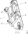
- perspektivisch und vergrößert eine Kulissen-Übertragungskomponente des Umlenkgetriebes.
- Ein Spielfahrzeug 1 ist als Straßenkehrmaschine ausgeführt und hat eine Mehrzahl von Funktionskomponenten, zu denen Kehrbürsten gehören, von denen in der
Fig. 1 eine Kehrbürste 2 dargestellt ist. Die Funktionskomponenten sind getragen von einer zweiteiligen Hubkomponente 3, deren beide Teile in derFig. 1 mit 3a und 3b bezeichnet sind. - Zur Hubverlagerung der Hubkomponente 3 dient ein Dreh-/Hub-Umlenkgetriebe 4, dessen Hauptkomponenten in den
Figuren 2 bis 4 dargestellt sind. -
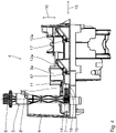
Fig. 2 zeigt das Umlenkgetriebe mit der Hubkomponente 3 beziehungsweise 3a in maximal angehobener Hubstellung. - Das Umlenkgetriebe 4 hat zur Betätigung eine Dreh-Getriebekomponente 5, deren eines Ende als Betätigungs-Drehknopf 6 und deren gegenüberliegendes Ende als Verzahnung 7 ausgeführt ist. Die Dreh-Getriebekomponente 5 ist insgesamt in Form eines Bolzens mit einer Längsachse gestaltet, die mit einer Drehachse 8 der Dreh-Getriebekomponente 6 zusammenfällt.
- Die Dreh-Getriebekomponente 5 ist axial an einem Rahmen 9 des Spielfahrzeugs 1 gelagert.
- Zur Vermittlung der Drehbewegung der Dreh-Getriebekomponente 5 in eine Hubverlagerung der Hubkomponente 3 längs einer Hubrichtung 10, die in den
Figuren 2 bis 4 vertikal verläuft, dient eine Kulissen-Übertragungskomponente 11, wie insgesamt in derFig. 5 dargestellt ist. Die Hubkomponente 3 ist ausschließlich in der Hubrichtung 10 verlagerbar. Diese Verlagerung längs der Hubrichtung 10 ist am Rahmen 9 geführt. - Die Kulissen-Übertragungskomponente 11 umfasst insgesamt vier schrägverlaufende Kulissenführungen 12, von denen zwei Kulissenführungen, die in der
Fig. 5 mit 12a bezeichnet sind, den Hubkomponenten-Teil 3a und zwei weitere Kulissenführungen 12, die in derFigur 5 mit 12b bezeichnet sind, dem anderen Hubkomponenten-Teil 12b zugeordnet sind. Eine Bewegungsbahn der Kulissenführungen 12 verläuft also schräg zur Hubrichtung 10. - Die Kulissen-Übertragungskomponente 11 ist lateral in einer in den
Figuren 2 bis 4 horizontalen Bewegungsrichtung 13 in einer Bewegungsebene, auf der die Hubrichtung 10 senkrecht steht, geführt zum Rahmen 9 verlagerbar. Diese Verlagerung wird angetrieben über ein Zahngetriebe 14, welches auf Seiten der Kulissen-Übertragungskomponente 11 eine Verzahnung 15 in einem Langloch 16 der Übertragungskomponenten 11 hat. Mit der Verzahnung 15 kämmt die Verzahnung 7 der Dreh-Getriebekomponente 5. Das Zahngetriebe 14 hat eine Geradverzahnung. - Die Verzahnung 15 ist einseitig in einer Innenwand des Langlochs 16 ausgeführt, nämlich an der Innenwand, die dem Betrachter der
Fig. 5 zugewandt ist. Die gegenüberliegende Innenwand des Langlochs 16 hat keine Verzahnungen, sondern ist glatt ausgeführt. - Mit den Kulissenführungen 12 (12a, 12b) wirken jeweils zugeordnete Kulissenbolzen 17 zusammen, die fest jeweils mit einem Teil 3a, 3b der Hubkomponente 3 verbunden sind. Die beiden in den
Figuren 2 bis 4 dargestellten Kulissenbolzen 17 sind fest mit dem Hubkomponenten-Teil 3a verbunden. - Zur Hubverlagerung der Funktionskomponenten des Spielfahrzeugs 1, also insbesondere der Kehrbürsten, beispielsweise zum Absenken der Kehrbürsten aus der in der
Figur 1 dargestellten, angehobenen Stellung, wird der Betätigungsknopf 6 um die Drehachse 8 gedreht. Über das Zahngetriebe 14 wird diese Drehbewegung in eine Lateralbewegung der Kulissen-Übertragungskomponente 11 längs der Bewegungsrichtung 13 in derFig. 2 nach rechts übertragen. Über die Kulisse mit den Kulissenführungen 12 und dem Kulissenbolzen 17 wird diese Lateralbewegung der Kulissen-Übertragungskomponente 11 in eine Hubbewegung der Hubkomponente 3 längs der Hubrichtung 10 in derFig. 2 nach unten überführt. Eine Bewegungsbahn der Kulisse 12, 17 verläuft dabei schräg zur Hubrichtung 10. -
Fig. 3 zeigt eine Zwischenposition mit teilweise abgesenkter Hubkomponente 3 (3a). -
Fig. 4 zeigt die Situation mit maximal abgesenkter Hubkomponente 3, 3a, bei der die Funktionskomponenten 2 so weit abgesenkt sind, dass sie mit der Fahrbahnoberfläche des Spielfahrzeugs 1 in Kontakt kommen. Über eine Reibschluss-Mechanik, die derjenigen entspricht, die für eine Heuwende-Baugruppe beschrieben ist, in derEP 2 476 469 B1 , werden in der abgesenkten Stellung der Hubkomponente 3 nachFig. 4 die Kehrbürsten 2 zur Rotation um deren Hochachsen angetrieben. - Die Komponenten des Dreh-/Hub-Umlenkgetriebes 4 sind als Kunststoff-Komponenten ausgeführt. Dies gilt insbesondere auch für die Kulissenbolzen 17.
- Das Dreh-/Hub-Umlenkgetriebe 4 weist insgesamt drei Komponenten auf, nämlich die Dreh-Getriebekomponente 5, die Kulissen-Übertragungskomponente 11 und die Hubkomponente 3.
- Die Komponenten des Spielfahrzeugs 1 sind als Kunststoffkomponenten ausgeführt, die insbesondere mittels Spritzguss herstellbar sind.
Claims (7)
- Dreh-/Hub-Umlenkgetriebe (4), ausgeführt aus Kunststoff-Komponenten, für ein Spielfahrzeug (1)- mit einer axial rahmenfest lagerbaren, um eine Drehachse (8) drehbaren Dreh-Getriebekomponente gekennzeichnet durch,- eine der Dreh-Getriebekomponente (5) gegenüber über eine Kulisse (12, 17), deren Bewegungsbahn schräg zu einer Hubrichtung (10) verläuft, verlagerbaren Hubkomponente (3, 3a, 3b),- mit einem Zahngetriebe (14) zum Übertragen einer Drehbewegung der Dreh-Getriebekomponente (5) in eine Lateralbewegung einer Getriebe-Komponente (11) in einer Bewegungsrichtung (13) in einer Bewegungsebene, auf der die Hubrichtung (10) senkrecht steht, wobei die Lateralbewegung der Getriebe-Komponente (11) über die Kulisse (12, 17) in eine Hubbewegung der Hubkomponente (3, 3a, 3b) umgesetzt wird.
- Umlenkgetriebe nach Anspruch 1, dadurch gekennzeichnet, dass die Hubkomponente (3, 3a, 3b) ausschließlich parallel zur Hubrichtung (10) verlagerbar ist, wobei das Dreh-/Hub-Umlenkgetriebe (4) eine lateral in der Bewegungsrichtung (13) in der Bewegungsebene, auf der die Hubrichtung (10) senkrecht steht, verlagerbare Kulissen-Übertragungskomponente (11) aufweist.
- Umlenkgetriebe nach Anspruch 1 oder 2, dadurch gekennzeichnet, dass das Zahngetriebe (14) ein verzahntes Langloch (16) in der Hubkomponente (3) und/oder in der Kulissen-Übertragungskomponente (11) aufweist.
- Umlenkgetriebe nach einem der Ansprüche 1 bis 3, dadurch gekennzeichnet, dass die Kulisse (12, 17) mindestens einen Kulissenbolzen (17) und eine schräg verlaufende Kulissenführung (12) zur Führung des Kulissenbolzens (17) aufweist.
- Umlenkgetriebe nach Anspruch 4, dadurch gekennzeichnet, dass der mindestens eine Kulissenbolzen (17) Teil der Hubkomponente (3) ist, wobei die zugeordnete Kulissenführung (2) Teil der Kulissen-Übertragungskomponente (11) ist.
- Spielfahrzeug mit einem Dreh-/Hub-Umlenkgetriebe (4) nach einem der Ansprüche 1 bis 5 und mit mindestens einer über das Dreh-/Hub-Umlenkgetriebe (4) hubverlagerbaren Funktionskomponente (2), die mit der Hubkomponente (3) verbunden ist.
- Spielfahrzeug nach Anspruch 6, ausgeführt als Straßenkehrmaschine.
Applications Claiming Priority (1)
| Application Number | Priority Date | Filing Date | Title |
|---|---|---|---|
| DE102020200277.0A DE102020200277B3 (de) | 2020-01-10 | 2020-01-10 | Dreh-/Hub-Umlenkgetriebe für ein Spielfahrzeug |
Publications (2)
| Publication Number | Publication Date |
|---|---|
| EP3848104A1 EP3848104A1 (de) | 2021-07-14 |
| EP3848104B1 true EP3848104B1 (de) | 2022-06-15 |
Family
ID=73043170
Family Applications (1)
| Application Number | Title | Priority Date | Filing Date |
|---|---|---|---|
| EP20205165.2A Active EP3848104B1 (de) | 2020-01-10 | 2020-11-02 | Dreh-/hub-umlenkgetriebe für ein spielfahrzeug |
Country Status (3)
| Country | Link |
|---|---|
| EP (1) | EP3848104B1 (de) |
| DE (1) | DE102020200277B3 (de) |
| PL (1) | PL3848104T3 (de) |
Families Citing this family (1)
| Publication number | Priority date | Publication date | Assignee | Title |
|---|---|---|---|---|
| USD952763S1 (en) * | 2021-01-11 | 2022-05-24 | Yanjun Zhong | Toy car |
Family Cites Families (3)
| Publication number | Priority date | Publication date | Assignee | Title |
|---|---|---|---|---|
| DE7419387U (de) * | 1974-06-05 | 1974-10-31 | Schickling H | Ein- und Doppelachs-Pferdetransportanhänger |
| DE202011001409U1 (de) * | 2011-01-12 | 2012-04-17 | Bruder Spielwaren Gmbh + Co. Kg | Spielzeug-Heuwender |
| DE102016200344B3 (de) * | 2016-01-14 | 2017-02-23 | Bruder Spielwaren Gmbh + Co. Kg | Spielfahrzeug |
-
2020
- 2020-01-10 DE DE102020200277.0A patent/DE102020200277B3/de active Active
- 2020-11-02 PL PL20205165.2T patent/PL3848104T3/pl unknown
- 2020-11-02 EP EP20205165.2A patent/EP3848104B1/de active Active
Also Published As
| Publication number | Publication date |
|---|---|
| DE102020200277B3 (de) | 2021-01-21 |
| EP3848104A1 (de) | 2021-07-14 |
| PL3848104T3 (pl) | 2022-10-03 |
Similar Documents
| Publication | Publication Date | Title |
|---|---|---|
| DE102017218492B4 (de) | Längseinsteller und fahrzeugsitz | |
| EP2217836B1 (de) | Schaltvorrichtung für ein getriebe | |
| DE102008049923B4 (de) | Vorrichtung zur Verstellung der Sitztiefe eines Fahrzeugs mit einer Sitzwanne | |
| DE4409324A1 (de) | Sicherheitsfußhebelwerk für ein Kraftfahrzeug | |
| EP2913577A1 (de) | Abdeckvorrichtung für Öffnungen, insbesondere für Maschinenöffnungen | |
| DE19853934B4 (de) | Schaltvorrichtung eines Kraftfahrzeuggetriebes | |
| DE19805924A1 (de) | Getriebe | |
| DE3027560A1 (de) | Sitz, insbes. kraftfahrzeugsitz | |
| WO2019115064A1 (de) | Türgriffanordnung einer fahrzeugtür | |
| EP3628891B1 (de) | Führungsanordnung mit mehreren führungsbahnen | |
| DE102015221720A1 (de) | Verfahren und Vorrichtung zum Betreiben eines Kraftfahrzeugs, Kraftfahrzeug | |
| EP3269622A2 (de) | Luftablenkvorrichtung für ein kraftfahrzeug | |
| DE102018220080A1 (de) | Kinematik für Fahrzeug-Klappe | |
| EP4182184A1 (de) | Baugruppe eines fahrzeugsitzes mit einer linearverstelleinrichtung | |
| DE102007027753B4 (de) | Zugmittelmechanismus, insbesondere für verstellbare Fahrzeugsitze | |
| EP1531290B1 (de) | Schalteinrichtung | |
| DE102005052342B4 (de) | Motorbetriebenes Lenksäulensystem eines Fahrzeuges | |
| DE102020200277B3 (de) | Dreh-/Hub-Umlenkgetriebe für ein Spielfahrzeug | |
| DE102012105375A1 (de) | Antriebssystem für bewegliches Fahrzeugelement | |
| EP2143859B1 (de) | Verriegelungsvorrichtung | |
| EP4427826B1 (de) | Getriebe-vorrichtung für ein spielzeug sowie spielzeug mit einer derartigen getriebe-vorrichtung | |
| DE60201307T2 (de) | Einstellvorrichtung zum Verstellen der Lage eines Pedals | |
| AT501549B1 (de) | Trittstufenantrieb | |
| DE102004025504B4 (de) | Verriegelung für einen Sitzlängsversteller | |
| DE60224783T2 (de) | Pedal fur ein kraftfahrzeug |
Legal Events
| Date | Code | Title | Description |
|---|---|---|---|
| PUAI | Public reference made under article 153(3) epc to a published international application that has entered the european phase |
Free format text: ORIGINAL CODE: 0009012 |
|
| STAA | Information on the status of an ep patent application or granted ep patent |
Free format text: STATUS: REQUEST FOR EXAMINATION WAS MADE |
|
| 17P | Request for examination filed |
Effective date: 20210608 |
|
| AK | Designated contracting states |
Kind code of ref document: A1 Designated state(s): AL AT BE BG CH CY CZ DE DK EE ES FI FR GB GR HR HU IE IS IT LI LT LU LV MC MK MT NL NO PL PT RO RS SE SI SK SM TR |
|
| GRAP | Despatch of communication of intention to grant a patent |
Free format text: ORIGINAL CODE: EPIDOSNIGR1 |
|
| STAA | Information on the status of an ep patent application or granted ep patent |
Free format text: STATUS: GRANT OF PATENT IS INTENDED |
|
| GRAJ | Information related to disapproval of communication of intention to grant by the applicant or resumption of examination proceedings by the epo deleted |
Free format text: ORIGINAL CODE: EPIDOSDIGR1 |
|
| STAA | Information on the status of an ep patent application or granted ep patent |
Free format text: STATUS: REQUEST FOR EXAMINATION WAS MADE |
|
| INTG | Intention to grant announced |
Effective date: 20211208 |
|
| RIN1 | Information on inventor provided before grant (corrected) |
Inventor name: PFEFFERLEIN, MARC |
|
| GRAP | Despatch of communication of intention to grant a patent |
Free format text: ORIGINAL CODE: EPIDOSNIGR1 |
|
| STAA | Information on the status of an ep patent application or granted ep patent |
Free format text: STATUS: GRANT OF PATENT IS INTENDED |
|
| INTC | Intention to grant announced (deleted) | ||
| INTG | Intention to grant announced |
Effective date: 20220113 |
|
| GRAS | Grant fee paid |
Free format text: ORIGINAL CODE: EPIDOSNIGR3 |
|
| RBV | Designated contracting states (corrected) |
Designated state(s): AL AT BE BG CH CY CZ DK EE ES FI FR GB GR HR HU IE IS IT LI LT LU LV MC MK MT NL NO PL PT RO RS SE SI SK SM TR |
|
| REG | Reference to a national code |
Ref country code: DE Ref legal event code: R108 |
|
| GRAA | (expected) grant |
Free format text: ORIGINAL CODE: 0009210 |
|
| STAA | Information on the status of an ep patent application or granted ep patent |
Free format text: STATUS: THE PATENT HAS BEEN GRANTED |
|
| AK | Designated contracting states |
Kind code of ref document: B1 Designated state(s): AL AT BE BG CH CY CZ DK EE ES FI FR GB GR HR HU IE IS IT LI LT LU LV MC MK MT NL NO PL PT RO RS SE SI SK SM TR |
|
| REG | Reference to a national code |
Ref country code: CH Ref legal event code: EP Ref country code: GB Ref legal event code: FG4D Free format text: NOT ENGLISH |
|
| REG | Reference to a national code |
Ref country code: IE Ref legal event code: FG4D Free format text: LANGUAGE OF EP DOCUMENT: GERMAN |
|
| REG | Reference to a national code |
Ref country code: AT Ref legal event code: REF Ref document number: 1498003 Country of ref document: AT Kind code of ref document: T Effective date: 20220715 |
|
| REG | Reference to a national code |
Ref country code: NL Ref legal event code: FP |
|
| REG | Reference to a national code |
Ref country code: LT Ref legal event code: MG9D |
|
| PG25 | Lapsed in a contracting state [announced via postgrant information from national office to epo] |
Ref country code: SE Free format text: LAPSE BECAUSE OF FAILURE TO SUBMIT A TRANSLATION OF THE DESCRIPTION OR TO PAY THE FEE WITHIN THE PRESCRIBED TIME-LIMIT Effective date: 20220615 Ref country code: NO Free format text: LAPSE BECAUSE OF FAILURE TO SUBMIT A TRANSLATION OF THE DESCRIPTION OR TO PAY THE FEE WITHIN THE PRESCRIBED TIME-LIMIT Effective date: 20220915 Ref country code: LT Free format text: LAPSE BECAUSE OF FAILURE TO SUBMIT A TRANSLATION OF THE DESCRIPTION OR TO PAY THE FEE WITHIN THE PRESCRIBED TIME-LIMIT Effective date: 20220615 Ref country code: HR Free format text: LAPSE BECAUSE OF FAILURE TO SUBMIT A TRANSLATION OF THE DESCRIPTION OR TO PAY THE FEE WITHIN THE PRESCRIBED TIME-LIMIT Effective date: 20220615 Ref country code: GR Free format text: LAPSE BECAUSE OF FAILURE TO SUBMIT A TRANSLATION OF THE DESCRIPTION OR TO PAY THE FEE WITHIN THE PRESCRIBED TIME-LIMIT Effective date: 20220916 Ref country code: FI Free format text: LAPSE BECAUSE OF FAILURE TO SUBMIT A TRANSLATION OF THE DESCRIPTION OR TO PAY THE FEE WITHIN THE PRESCRIBED TIME-LIMIT Effective date: 20220615 Ref country code: BG Free format text: LAPSE BECAUSE OF FAILURE TO SUBMIT A TRANSLATION OF THE DESCRIPTION OR TO PAY THE FEE WITHIN THE PRESCRIBED TIME-LIMIT Effective date: 20220915 |
|
| PG25 | Lapsed in a contracting state [announced via postgrant information from national office to epo] |
Ref country code: RS Free format text: LAPSE BECAUSE OF FAILURE TO SUBMIT A TRANSLATION OF THE DESCRIPTION OR TO PAY THE FEE WITHIN THE PRESCRIBED TIME-LIMIT Effective date: 20220615 Ref country code: LV Free format text: LAPSE BECAUSE OF FAILURE TO SUBMIT A TRANSLATION OF THE DESCRIPTION OR TO PAY THE FEE WITHIN THE PRESCRIBED TIME-LIMIT Effective date: 20220615 |
|
| PG25 | Lapsed in a contracting state [announced via postgrant information from national office to epo] |
Ref country code: SM Free format text: LAPSE BECAUSE OF FAILURE TO SUBMIT A TRANSLATION OF THE DESCRIPTION OR TO PAY THE FEE WITHIN THE PRESCRIBED TIME-LIMIT Effective date: 20220615 Ref country code: SK Free format text: LAPSE BECAUSE OF FAILURE TO SUBMIT A TRANSLATION OF THE DESCRIPTION OR TO PAY THE FEE WITHIN THE PRESCRIBED TIME-LIMIT Effective date: 20220615 Ref country code: RO Free format text: LAPSE BECAUSE OF FAILURE TO SUBMIT A TRANSLATION OF THE DESCRIPTION OR TO PAY THE FEE WITHIN THE PRESCRIBED TIME-LIMIT Effective date: 20220615 Ref country code: PT Free format text: LAPSE BECAUSE OF FAILURE TO SUBMIT A TRANSLATION OF THE DESCRIPTION OR TO PAY THE FEE WITHIN THE PRESCRIBED TIME-LIMIT Effective date: 20221017 Ref country code: ES Free format text: LAPSE BECAUSE OF FAILURE TO SUBMIT A TRANSLATION OF THE DESCRIPTION OR TO PAY THE FEE WITHIN THE PRESCRIBED TIME-LIMIT Effective date: 20220615 Ref country code: EE Free format text: LAPSE BECAUSE OF FAILURE TO SUBMIT A TRANSLATION OF THE DESCRIPTION OR TO PAY THE FEE WITHIN THE PRESCRIBED TIME-LIMIT Effective date: 20220615 |
|
| PG25 | Lapsed in a contracting state [announced via postgrant information from national office to epo] |
Ref country code: IS Free format text: LAPSE BECAUSE OF FAILURE TO SUBMIT A TRANSLATION OF THE DESCRIPTION OR TO PAY THE FEE WITHIN THE PRESCRIBED TIME-LIMIT Effective date: 20221015 |
|
| PG25 | Lapsed in a contracting state [announced via postgrant information from national office to epo] |
Ref country code: AL Free format text: LAPSE BECAUSE OF FAILURE TO SUBMIT A TRANSLATION OF THE DESCRIPTION OR TO PAY THE FEE WITHIN THE PRESCRIBED TIME-LIMIT Effective date: 20220615 |
|
| PLBE | No opposition filed within time limit |
Free format text: ORIGINAL CODE: 0009261 |
|
| STAA | Information on the status of an ep patent application or granted ep patent |
Free format text: STATUS: NO OPPOSITION FILED WITHIN TIME LIMIT |
|
| PG25 | Lapsed in a contracting state [announced via postgrant information from national office to epo] |
Ref country code: DK Free format text: LAPSE BECAUSE OF FAILURE TO SUBMIT A TRANSLATION OF THE DESCRIPTION OR TO PAY THE FEE WITHIN THE PRESCRIBED TIME-LIMIT Effective date: 20220615 |
|
| 26N | No opposition filed |
Effective date: 20230316 |
|
| PG25 | Lapsed in a contracting state [announced via postgrant information from national office to epo] |
Ref country code: SI Free format text: LAPSE BECAUSE OF FAILURE TO SUBMIT A TRANSLATION OF THE DESCRIPTION OR TO PAY THE FEE WITHIN THE PRESCRIBED TIME-LIMIT Effective date: 20220615 |
|
| P01 | Opt-out of the competence of the unified patent court (upc) registered |
Effective date: 20230519 |
|
| PG25 | Lapsed in a contracting state [announced via postgrant information from national office to epo] |
Ref country code: MC Free format text: LAPSE BECAUSE OF FAILURE TO SUBMIT A TRANSLATION OF THE DESCRIPTION OR TO PAY THE FEE WITHIN THE PRESCRIBED TIME-LIMIT Effective date: 20220615 |
|
| PG25 | Lapsed in a contracting state [announced via postgrant information from national office to epo] |
Ref country code: LU Free format text: LAPSE BECAUSE OF NON-PAYMENT OF DUE FEES Effective date: 20221102 |
|
| PG25 | Lapsed in a contracting state [announced via postgrant information from national office to epo] |
Ref country code: IE Free format text: LAPSE BECAUSE OF NON-PAYMENT OF DUE FEES Effective date: 20221102 |
|
| PG25 | Lapsed in a contracting state [announced via postgrant information from national office to epo] |
Ref country code: CY Free format text: LAPSE BECAUSE OF FAILURE TO SUBMIT A TRANSLATION OF THE DESCRIPTION OR TO PAY THE FEE WITHIN THE PRESCRIBED TIME-LIMIT Effective date: 20220615 |
|
| PG25 | Lapsed in a contracting state [announced via postgrant information from national office to epo] |
Ref country code: MK Free format text: LAPSE BECAUSE OF FAILURE TO SUBMIT A TRANSLATION OF THE DESCRIPTION OR TO PAY THE FEE WITHIN THE PRESCRIBED TIME-LIMIT Effective date: 20220615 |
|
| REG | Reference to a national code |
Ref country code: CH Ref legal event code: PL |
|
| PG25 | Lapsed in a contracting state [announced via postgrant information from national office to epo] |
Ref country code: CH Free format text: LAPSE BECAUSE OF NON-PAYMENT OF DUE FEES Effective date: 20231130 |
|
| PG25 | Lapsed in a contracting state [announced via postgrant information from national office to epo] |
Ref country code: HU Free format text: LAPSE BECAUSE OF FAILURE TO SUBMIT A TRANSLATION OF THE DESCRIPTION OR TO PAY THE FEE WITHIN THE PRESCRIBED TIME-LIMIT; INVALID AB INITIO Effective date: 20201102 Ref country code: CH Free format text: LAPSE BECAUSE OF NON-PAYMENT OF DUE FEES Effective date: 20231130 |
|
| PG25 | Lapsed in a contracting state [announced via postgrant information from national office to epo] |
Ref country code: MT Free format text: LAPSE BECAUSE OF FAILURE TO SUBMIT A TRANSLATION OF THE DESCRIPTION OR TO PAY THE FEE WITHIN THE PRESCRIBED TIME-LIMIT Effective date: 20220615 |
|
| PG25 | Lapsed in a contracting state [announced via postgrant information from national office to epo] |
Ref country code: BG Free format text: LAPSE BECAUSE OF FAILURE TO SUBMIT A TRANSLATION OF THE DESCRIPTION OR TO PAY THE FEE WITHIN THE PRESCRIBED TIME-LIMIT Effective date: 20220615 |
|
| PG25 | Lapsed in a contracting state [announced via postgrant information from national office to epo] |
Ref country code: BG Free format text: LAPSE BECAUSE OF FAILURE TO SUBMIT A TRANSLATION OF THE DESCRIPTION OR TO PAY THE FEE WITHIN THE PRESCRIBED TIME-LIMIT Effective date: 20220615 |
|
| PG25 | Lapsed in a contracting state [announced via postgrant information from national office to epo] |
Ref country code: TR Free format text: LAPSE BECAUSE OF FAILURE TO SUBMIT A TRANSLATION OF THE DESCRIPTION OR TO PAY THE FEE WITHIN THE PRESCRIBED TIME-LIMIT Effective date: 20220615 |
|
| PGFP | Annual fee paid to national office [announced via postgrant information from national office to epo] |
Ref country code: NL Payment date: 20251119 Year of fee payment: 6 |
|
| PGFP | Annual fee paid to national office [announced via postgrant information from national office to epo] |
Ref country code: GB Payment date: 20251120 Year of fee payment: 6 |
|
| PGFP | Annual fee paid to national office [announced via postgrant information from national office to epo] |
Ref country code: AT Payment date: 20260113 Year of fee payment: 5 |
|
| PGFP | Annual fee paid to national office [announced via postgrant information from national office to epo] |
Ref country code: IT Payment date: 20251128 Year of fee payment: 6 |
|
| PGFP | Annual fee paid to national office [announced via postgrant information from national office to epo] |
Ref country code: FR Payment date: 20251120 Year of fee payment: 6 |
|
| PGFP | Annual fee paid to national office [announced via postgrant information from national office to epo] |
Ref country code: BE Payment date: 20251118 Year of fee payment: 6 |
|
| PGFP | Annual fee paid to national office [announced via postgrant information from national office to epo] |
Ref country code: CZ Payment date: 20251017 Year of fee payment: 6 |
|
| PGFP | Annual fee paid to national office [announced via postgrant information from national office to epo] |
Ref country code: PL Payment date: 20251008 Year of fee payment: 6 |
|
| PG25 | Lapsed in a contracting state [announced via postgrant information from national office to epo] |
Ref country code: CH Free format text: THE PATENT HAS BEEN ANNULLED BY A DECISION OF A NATIONAL AUTHORITY Effective date: 20231130 |