EP3847733B1 - System zum laden von drahtloskommunikationsvorrichtungen - Google Patents
System zum laden von drahtloskommunikationsvorrichtungen Download PDFInfo
- Publication number
- EP3847733B1 EP3847733B1 EP18783599.6A EP18783599A EP3847733B1 EP 3847733 B1 EP3847733 B1 EP 3847733B1 EP 18783599 A EP18783599 A EP 18783599A EP 3847733 B1 EP3847733 B1 EP 3847733B1
- Authority
- EP
- European Patent Office
- Prior art keywords
- case
- wireless devices
- processors
- transceiver
- capacitive sensing
- Prior art date
- Legal status (The legal status is an assumption and is not a legal conclusion. Google has not performed a legal analysis and makes no representation as to the accuracy of the status listed.)
- Active
Links
Images







Classifications
-
- H—ELECTRICITY
- H02—GENERATION; CONVERSION OR DISTRIBUTION OF ELECTRIC POWER
- H02J—ELECTRIC POWER NETWORKS; CIRCUIT ARRANGEMENTS OR SYSTEMS FOR SUPPLYING OR DISTRIBUTING ELECTRIC POWER; SYSTEMS FOR STORING ELECTRIC ENERGY
- H02J7/00—Circuit arrangements for charging or discharging batteries or for supplying loads from batteries
- H02J7/60—Circuit arrangements for charging or discharging batteries or for supplying loads from batteries including safety or protection arrangements
- H02J7/685—Circuit arrangements for charging or discharging batteries or for supplying loads from batteries including safety or protection arrangements using connection detecting circuits
-
- A—HUMAN NECESSITIES
- A45—HAND OR TRAVELLING ARTICLES
- A45C—PURSES; LUGGAGE; HAND CARRIED BAGS
- A45C11/00—Receptacles for purposes not provided for in groups A45C1/00-A45C9/00
- A45C11/002—Receptacles for purposes not provided for in groups A45C1/00-A45C9/00 for storing portable handheld communication devices, e.g. pagers or smart phones
-
- A—HUMAN NECESSITIES
- A45—HAND OR TRAVELLING ARTICLES
- A45C—PURSES; LUGGAGE; HAND CARRIED BAGS
- A45C15/00—Purses, bags, luggage or other receptacles covered by groups A45C1/00 - A45C11/00, combined with other objects or articles
-
- H—ELECTRICITY
- H02—GENERATION; CONVERSION OR DISTRIBUTION OF ELECTRIC POWER
- H02J—ELECTRIC POWER NETWORKS; CIRCUIT ARRANGEMENTS OR SYSTEMS FOR SUPPLYING OR DISTRIBUTING ELECTRIC POWER; SYSTEMS FOR STORING ELECTRIC ENERGY
- H02J50/00—Circuit arrangements or systems for wireless supply or distribution of electric power
- H02J50/005—Mechanical details of housing or structure aiming to accommodate the power transfer means, e.g. mechanical integration of coils, antennas or transducers into emitting or receiving devices
-
- H—ELECTRICITY
- H02—GENERATION; CONVERSION OR DISTRIBUTION OF ELECTRIC POWER
- H02J—ELECTRIC POWER NETWORKS; CIRCUIT ARRANGEMENTS OR SYSTEMS FOR SUPPLYING OR DISTRIBUTING ELECTRIC POWER; SYSTEMS FOR STORING ELECTRIC ENERGY
- H02J50/00—Circuit arrangements or systems for wireless supply or distribution of electric power
- H02J50/90—Circuit arrangements or systems for wireless supply or distribution of electric power involving detection or optimisation of position, e.g. alignment
-
- H—ELECTRICITY
- H02—GENERATION; CONVERSION OR DISTRIBUTION OF ELECTRIC POWER
- H02J—ELECTRIC POWER NETWORKS; CIRCUIT ARRANGEMENTS OR SYSTEMS FOR SUPPLYING OR DISTRIBUTING ELECTRIC POWER; SYSTEMS FOR STORING ELECTRIC ENERGY
- H02J7/00—Circuit arrangements for charging or discharging batteries or for supplying loads from batteries
- H02J7/40—Circuit arrangements for charging or discharging batteries or for supplying loads from batteries characterised by the exchange of charge or discharge related data
- H02J7/443—Circuit arrangements for charging or discharging batteries or for supplying loads from batteries characterised by the exchange of charge or discharge related data using passive battery identification means, e.g. resistors or capacitors
-
- H—ELECTRICITY
- H02—GENERATION; CONVERSION OR DISTRIBUTION OF ELECTRIC POWER
- H02J—ELECTRIC POWER NETWORKS; CIRCUIT ARRANGEMENTS OR SYSTEMS FOR SUPPLYING OR DISTRIBUTING ELECTRIC POWER; SYSTEMS FOR STORING ELECTRIC ENERGY
- H02J7/00—Circuit arrangements for charging or discharging batteries or for supplying loads from batteries
- H02J7/70—Circuit arrangements for charging or discharging batteries or for supplying loads from batteries characterised by the mechanical construction
- H02J7/731—Circuit arrangements for charging or discharging batteries or for supplying loads from batteries characterised by the mechanical construction specially adapted for holding portable devices containing batteries
-
- H—ELECTRICITY
- H02—GENERATION; CONVERSION OR DISTRIBUTION OF ELECTRIC POWER
- H02J—ELECTRIC POWER NETWORKS; CIRCUIT ARRANGEMENTS OR SYSTEMS FOR SUPPLYING OR DISTRIBUTING ELECTRIC POWER; SYSTEMS FOR STORING ELECTRIC ENERGY
- H02J7/00—Circuit arrangements for charging or discharging batteries or for supplying loads from batteries
- H02J7/70—Circuit arrangements for charging or discharging batteries or for supplying loads from batteries characterised by the mechanical construction
- H02J7/751—Circuit arrangements for charging or discharging batteries or for supplying loads from batteries characterised by the mechanical construction concerning the insertion or the connection of the batteries
-
- H—ELECTRICITY
- H04—ELECTRIC COMMUNICATION TECHNIQUE
- H04R—LOUDSPEAKERS, MICROPHONES, GRAMOPHONE PICK-UPS OR LIKE ACOUSTIC ELECTROMECHANICAL TRANSDUCERS; ELECTRIC HEARING AIDS; PUBLIC ADDRESS SYSTEMS
- H04R1/00—Details of transducers, loudspeakers or microphones
- H04R1/10—Earpieces; Attachments therefor ; Earphones; Monophonic headphones
- H04R1/1016—Earpieces of the intra-aural type
-
- H—ELECTRICITY
- H04—ELECTRIC COMMUNICATION TECHNIQUE
- H04R—LOUDSPEAKERS, MICROPHONES, GRAMOPHONE PICK-UPS OR LIKE ACOUSTIC ELECTROMECHANICAL TRANSDUCERS; ELECTRIC HEARING AIDS; PUBLIC ADDRESS SYSTEMS
- H04R1/00—Details of transducers, loudspeakers or microphones
- H04R1/10—Earpieces; Attachments therefor ; Earphones; Monophonic headphones
- H04R1/1025—Accumulators specially adapted for earpieces; Arrangements specially adapted for charging thereof
-
- H—ELECTRICITY
- H02—GENERATION; CONVERSION OR DISTRIBUTION OF ELECTRIC POWER
- H02J—ELECTRIC POWER NETWORKS; CIRCUIT ARRANGEMENTS OR SYSTEMS FOR SUPPLYING OR DISTRIBUTING ELECTRIC POWER; SYSTEMS FOR STORING ELECTRIC ENERGY
- H02J2105/00—Networks for supplying or distributing electric power characterised by their spatial reach or by the load
- H02J2105/40—Networks for supplying or distributing electric power characterised by their spatial reach or by the load characterised by the loads connecting to the networks or being supplied by the networks
- H02J2105/44—Portable electronic devices
-
- H—ELECTRICITY
- H02—GENERATION; CONVERSION OR DISTRIBUTION OF ELECTRIC POWER
- H02J—ELECTRIC POWER NETWORKS; CIRCUIT ARRANGEMENTS OR SYSTEMS FOR SUPPLYING OR DISTRIBUTING ELECTRIC POWER; SYSTEMS FOR STORING ELECTRIC ENERGY
- H02J7/00—Circuit arrangements for charging or discharging batteries or for supplying loads from batteries
- H02J7/34—Parallel operation in networks using both storage and other DC sources, e.g. providing buffering
- H02J7/342—The other DC source being a battery actively interacting with the first one, i.e. battery to battery charging
-
- H—ELECTRICITY
- H02—GENERATION; CONVERSION OR DISTRIBUTION OF ELECTRIC POWER
- H02J—ELECTRIC POWER NETWORKS; CIRCUIT ARRANGEMENTS OR SYSTEMS FOR SUPPLYING OR DISTRIBUTING ELECTRIC POWER; SYSTEMS FOR STORING ELECTRIC ENERGY
- H02J7/00—Circuit arrangements for charging or discharging batteries or for supplying loads from batteries
- H02J7/40—Circuit arrangements for charging or discharging batteries or for supplying loads from batteries characterised by the exchange of charge or discharge related data
- H02J7/42—Circuit arrangements for charging or discharging batteries or for supplying loads from batteries characterised by the exchange of charge or discharge related data with electronic devices having internal batteries, e.g. mobile phones
-
- H—ELECTRICITY
- H02—GENERATION; CONVERSION OR DISTRIBUTION OF ELECTRIC POWER
- H02J—ELECTRIC POWER NETWORKS; CIRCUIT ARRANGEMENTS OR SYSTEMS FOR SUPPLYING OR DISTRIBUTING ELECTRIC POWER; SYSTEMS FOR STORING ELECTRIC ENERGY
- H02J7/00—Circuit arrangements for charging or discharging batteries or for supplying loads from batteries
- H02J7/50—Circuit arrangements for charging or discharging batteries or for supplying loads from batteries acting upon multiple batteries simultaneously or sequentially
-
- H—ELECTRICITY
- H02—GENERATION; CONVERSION OR DISTRIBUTION OF ELECTRIC POWER
- H02J—ELECTRIC POWER NETWORKS; CIRCUIT ARRANGEMENTS OR SYSTEMS FOR SUPPLYING OR DISTRIBUTING ELECTRIC POWER; SYSTEMS FOR STORING ELECTRIC ENERGY
- H02J9/00—Circuit arrangements for emergency or stand-by power supply, e.g. for emergency lighting
- H02J9/005—Circuit arrangements for emergency or stand-by power supply, e.g. for emergency lighting using a power saving mode
-
- H—ELECTRICITY
- H04—ELECTRIC COMMUNICATION TECHNIQUE
- H04R—LOUDSPEAKERS, MICROPHONES, GRAMOPHONE PICK-UPS OR LIKE ACOUSTIC ELECTROMECHANICAL TRANSDUCERS; ELECTRIC HEARING AIDS; PUBLIC ADDRESS SYSTEMS
- H04R2460/00—Details of hearing devices, i.e. of ear- or headphones covered by H04R1/10 or H04R5/033 but not provided for in any of their subgroups, or of hearing aids covered by H04R25/00 but not provided for in any of its subgroups
- H04R2460/17—Hearing device specific tools used for storing or handling hearing devices or parts thereof, e.g. placement in the ear, replacement of cerumen barriers, repair, cleaning hearing devices
Definitions
- the proposed solution relates to a case as defined by independent claim 1 and to a method as defined by independent claim 9. Potential embodiments are in particular defined by the accompanying dependent claims.
- the capacitive sensing circuitry may be configured to send the sensing pulses at a predetermined low sampling rate when the wireless devices are detected, since it may be assumed that the wireless devices were inserted for charging or storage for at least some period of time, and at a predetermined high sampling rate when the wireless devices are not detected, thus reducing latency of detecting insertion of the wireless devices.
- the one or more processors may further reserve power for the case by deactivating the capacitive sensing circuitry, the transceivers, the Hall-Effect sensor, the input/output/sensing line, and/or the electrical component.
- the one or more processors may generate a high impedance signal (high-Z logic state of a tristate logic gate) at the input/output/sensing line, which is in turn passed through the electrical component. This high-impedance signal effectively removes the influence of the input/output/sensing line and the electrical component from the rest of the circuitry and thereby reduces energy loss and corrosion on the input/output/sensing line and the electrical component.
- the case 100 and the wireless device 180 may transmit data to each other in a sequential fashion.
- the case 100 and the wireless device 180 may take turns transmitting data for fixed periods of time (such as 10 ms of communication in each direction).
- the case 100 and/or the wireless device 180 may be configured to indicate when it has no more data to transmit and is ready to receive data, and such an indication may cause communication to reverse in direction.
- the one or more processors 140 may control the sequence of communication.
- the one or more processors 140 may determine the appropriate direction and frequency of communication based on detection data from the capacitive sensing circuitry 120. For example, upon receiving detection data that the wireless device 180 has been positioned into the case 100, the one or more processors 140 may generate a control signal to enable the transceiver 150 for initiating communication with the wireless device 180. As another example, upon receiving detection data that the wireless device 180 is removed from the case 100, the one or more processors 140 may generate a control signal to disable the transceiver 150.
- FIGS. 1 , 3 and 4 show only one wireless device 180
- the case 100 may be configured for charging multiple wireless devices, such as a pair of wireless earbuds.
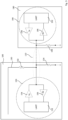
- FIG. 5 is a simplified circuit diagram of the example case 100 with two wireless devices 180A and 180B.
- the two wireless devices 180A and 180B may have the same or different circuitry.
- the two wireless devices 180A and 180B are each provided with a connection to the electrical component 110.
- the electrical component 110 is a single wire
- the two wireless devices 180A and 180B may each have an electrical contact that makes contact with the single wire.
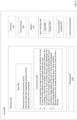
- FIG. 6 shows an example case 600 for charging one or more wireless devices.
- the case 600 may include one or more processors 630, one or more memories 620, as well as other components.
- the case 600 may further include a battery 612, one or more transceivers 614, and one or more sensors 616.
- the case 600 may further include a user interface 640, a communication module 650, and one or more internal clocks 660.
- the case 600 may include some or all of the features of the case 100 in FIGS. 1 , 3 and 5 , or some or all of the features of the case 100A in FIG. 4 .
- the one or more processors 630 may include the one or more processors 140 in FIGS. 1 or 3-5 .
- the data 622 may be retrieved, stored or modified by the one or more processors 630 in accordance with the instructions 628.
- data 622 may include detection data from the sensors 616, which may indicate whether the case 600 is open or closed, or whether a wireless device is detected inside the case 600.
- the data 622 may also include data received through the one or more transceivers 614, such as battery life information of the wireless device positioned inside the case 600.
- the one or more processors 630 may control the sensors 616, the transceivers 614, and/or the battery 612 based on the data 622.
- the instructions 628 may be any set of instructions to be executed directly (such as machine code) or indirectly (such as scripts) by the one or more processors 630.
- the instructions may be stored as computing device code on the computing device-readable medium.
- the terms "instructions” and “programs” may be used interchangeably herein.
- the instructions may be stored in object code format for direct processing by the processor, or in any other computing device language including scripts or collections of independent source code modules that are interpreted on demand or compiled in advance. Functions, methods and routines of the instructions are explained in more detail below.
- the one or more processors 630 may be microprocessors, logic circuitry (e.g., logic gates, flip-flops, etc.) hard-wired into the case 600, or may be a dedicated application specific integrated circuit (ASIC). It should be understood that the one or more processors 630 are not limited to hard-wired logic circuitry, but may also include any commercially available processing unit, or any hardware-based processors, such as a field programmable gate array (FPGA). In some examples, the one or more processors 630 may include a state machine.
- logic circuitry e.g., logic gates, flip-flops, etc.
- ASIC application specific integrated circuit
- FPGA field programmable gate array
- the one or more processors 630 may include a state machine.
- the communication module 650 may include a wireless network connection module, a wireless ad hoc connection module, and/or a wired connection module.
- the wireless network connection module may be configured to support communication via cellular, LTE, 4G, WiFi, GPS, and other networked architectures.
- the wireless ad hoc connection module may be configured to support Bluetooth ® , Bluetooth LE, near field communications, and other non-networked wireless arrangements.
- the wired connection may include a USB, micro USB, USB type C or other connector, for example to receive data and/or power from a laptop, tablet, smartphone or other device.
- the one or more internal clocks 660 provide timing information, which can be used for time measurement in various operations run by the one or more processors 630, the one or more transceivers 614, the one or more sensors 616, and/or the communication module 650. For example, using the one or more internal clocks 660, the one or more processors 630 may determine that a wireless device had been positioned in it for a predetermined period of time (such as 7 days), thus the wireless device is likely completely discharged.
- a predetermined period of time such as 7 days
- example methods are now described. Such methods may be performed using the systems described above, modifications thereof, or any of a variety of systems having different configurations. It should be understood that the operations involved in the following methods need not be performed in the precise order described. Rather, various operations may be handled in a different order or simultaneously, and operations may be added or omitted.
- capacitive sensing is deactivated. For example, if the capacitive sensing circuitry 120 had previously been activated, the one or more processors 140 can generate a control signal to deactivate the capacitive sensing circuitry 120 upon receiving detection data indicating that the case was closed; if the capacitive sensing circuitry 120 had not been activated, the one or more processors 140 need not do anything further. Conversely, in block 716, if it was detected that the case was open, capacitive sensing is activated.
- the one or more processors 140 can generate a control signal to activate the capacitive sensing circuitry 120 upon receiving detection data indicating that the case was opened; if the capacitive sensing circuitry 120 had not been deactivated, the one or more processors 140 need not do anything further.
- a device it is determined whether a device is in the case. For example, if the case 100 is open and capacitive sensing circuitry 120 is activated (block 716), the one or more processors 140 may receive detection data from capacitive sensing circuitry 120 indicating whether the wireless device 180 is inside the case 100. As another example, if the case 100 is closed and capacitive sensing circuitry 120 is deactivated (block 714), the one or more processors 140 may look at previous detection data saved in memory indicating whether the wireless device 180 had been detected in the case 100.
- the one or more processors 140 may generate a control signal to transceiver 150 to receive data from the wireless device 180.
- the case charges the device.
- the one or more processors 140 may receive no data from the transceiver 150, and assumes that the wireless device 180 did not respond to communication initiated by the transceiver 150.
- the one or more processors 140 may assume that the failure to respond is because the wireless device 180 is completely discharged, and thus generate a control signal to enable charging of the wireless device 180.
- the case continues to ping the device (block 724) to see whether the device can respond to communication, and repeat any steps described above as necessary.
- the transceiver 150 may receive charge status from the wireless device 180, and report to the one or more processors 140, the one or more processors 140 may determine whether the charge status is fully charged, or alternatively at or above a predetermined sufficient charge threshold (such as 70% charged, 80% charged, etc.). If it is determined that the device is not sufficiently charged, the case charges the device (block 732). Otherwise, in block 736, if it is determined that the device is sufficiently charged, the case does not charge the device. For example, the one or more processors 140 generates a control signal to disable charging of the wireless device 180. Further, the electrical component is disabled (block 722). Thereafter, the case continues to monitor whether the case is opened (block 712) and repeat any steps described above as necessary, including detecting whether the device is in the case, and whether the device is sufficiently charged.
- a predetermined sufficient charge threshold such as 70% charged, 80% charged, etc.
- any of a number of other data may also be used to control sensing and charging.
- a user may manually enable and disable sensing and charging, such as via a user input of the case (such as user interface 640).
- whether various sensing, communication, and charging capabilities, and/or the electrical component are disabled or enabled may depend on a charge status of the case itself.
- one or more sensing, communication, and charging capabilities may be turned off when the case has a predetermined critically low charge status (such as less than 10% charged, 5% charged, or another low charge level).
- sensing, communication, and charging capabilities, and/or the electrical component may depend on whether the case is in standby state, active state, or factory mode. For example, one or more sensing, communication, and charging capabilities may be turned off when the case is in standby state or factory mode.
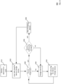
- FIG. 8 provides an example flow diagram illustrating an example method 800 for controlling a capacitive sensing circuitry in a case for detecting a presence of a wireless device.
- the one or more processors 140 of case 100 or 100A shown in FIGS. 1 and 3-5 may be used to control the capacitive sensing circuitry 120 according to the method 700.
- the processors 140 may control the capacitive sensing circuitry 120 based on detections from the proximity sensor 160 and the capacitive sensing circuitry 120.
- the case is in factory mode-where a fully charged device is packaged in the case.
- most or all components of the case may be in an inactive or standby state, such as capacitive sensing circuitry 120, transceiver 150, electrical component 110, and charging capabilities.
- only the proximity sensor 160 may be active in this factory mode to detect whether the case 100 opens (indicating that the case 100 has reached a user, who may take the packaged device 180 out of the case 100).
- the one or more processors 140 may receive detection data from the proximity sensor 160 indicating whether the case 100 is open. If the case is not open, the case remains in factory mode (block 810). However, in block 822, if it is determined that the case is opened, capacitive sensing is activated. For example, the one or more processors 140 can generate a control signal to activate the capacitive sensing circuitry 120 upon receiving detection data indicating that the case was opened.
- the one or more processors 140 may receive detection data from capacitive sensing circuitry 120 indicating whether the wireless device 180 is inside the case 100. If the device is in the case, in block 832, capacitive sensing polls at a low sampling rate. For example, the one or more processors 140 may receive detection data that the wireless device 180 is in the case 100, and assumes that either the user wants the case to charge the wireless device 180 or to store the device for some period of time, and therefore generates a control signal to the capacitive sensing circuitry 120 to poll at a predetermined low sampling rate (such as 1kHz-10kHz).
- a predetermined low sampling rate such as 1kHz-10kHz
- capacitive sensing polls at a high sampling rate may be received from the one or more processors 140 from the one or more processors 140, and assumes that once the user returns the wireless device 180 to the case 100, some action (such as charging) may be needed right away, thus, the one or more processors 140 may generates a control signal to the capacitive sensing circuitry 120 to poll at a predetermined high sampling rate (such as up to 100kHz).
- a predetermined high sampling rate such as up to 100kHz.
- FIG. 9 provides an example flow diagram illustrating an example method 900 for controlling communication between a case and a wireless device.
- the one or more processors 140 of case 100 or 100A shown in FIGS. 1 and 3-5 may be used to control the transceiver 150 according to the method 900.
- the processors 140 may control the transceiver 150 based on detections from the proximity sensor 160, the capacitive sensing circuitry 120, and the data received by the transceiver 150.
- the device is detected inside the case.
- the one or more processors 140 may receive detection data from capacitive sensing circuitry 120 indicating that the wireless device 180 is inside the case 100.
- the one or more processors 140 may look at previous detection data saved in memory indicating that the wireless device 180 had been detected in the case 100.
- the case pings the device at a low rate for its charge status.
- the one or more processors 140 may generate a control signal to transceiver 150 to ping the wireless device 180 at a predetermined low communication rate (such as 1Hz-10Hz).
- the one or more processors 140 may generate a control signal to transceiver 150 to receive data from the wireless device 180.
- the case charges the device.
- the one or more processors 140 may receive no data from the transceiver 150, and assumes that the wireless device 180 did not respond to communication initiated by the transceiver 150.
- the one or more processors 140 may assume that the failure to respond is because the wireless device 180 is completely discharged, and thus generate a control signal to enable charging of the wireless device 180.
- the case pings the device at a high rate for its charge status.
- the one or more processors 140 may generate a control signal to transceiver 150 to ping the wireless device 180 at a predetermined high communication rate (such as up to 100Hz).
- the low rate may be determined by an amount of time it would take for all or a predetermined amount of charges to drain from the wireless device 180.
- communication rate can be set additionally based on other factors, such as whether the device is in factory mode (low communication rate) or working mode (high communication rate). Further, communication rate may be further based on a status of the case, such as whether the case is in standby state/factory mode (low communication rate) or active state (high communication rate), whether the case is open (high communication rate) or closed (low communication rate), whether the case has a predetermined critically low charge (low communication rate) or not (high communication rate).
- FIG. 10 provides an example flow diagram illustrating an example method 1000 for controlling charging of a wireless device in a case.
- the one or more processors 140 of case 100 or 100A shown in FIGS. 1 and 3-5 may be used to control charging the wireless device 180 according to the method 1000.
- the case 100 or 100A may control charging based on detections from capacitive sensing circuitry 120 and proximity sensor 160, and data received from transceiver 150.
- the case charges the device.
- the one or more processors 140 may receive no data from the transceiver 150, and assumes that the wireless device 180 did not respond to communication initiated by the transceiver 150.
- the one or more processors 140 may assume that the failure to respond is because the wireless device 180 is completely discharged, and thus generate a control signal to enable charging of the wireless device 180.
- the case continues to ping the device for its charge status (block 1020). Thereafter, the case continues to monitor whether the wireless device can respond to communication (block 1030), and repeat any steps described above as necessary.
- the case 100 may be further configured to conserve energy when its charge status is at a predetermined critically low level.
- the predetermined critically low charge may be a predetermined value, such as 10% charged, 5% charged, or another low charge level.
- the transceiver 150 may receive charge status from the wireless device 180, and report to the one or more processors 140, the one or more processors 140 may determine whether the charge status is at or above a predetermined minimal charge threshold.
- the predetermined minimal charge threshold may be the amount of charge needed for the wireless device 180 to turn on or transmit its charge status.
- the case does not charge the device.
- the one or more processors 140 may generate a control signal to disable charging of the wireless device 180. Thereafter, though not shown, the case continues to ping the device for its charge status (block 1020). If, however, it is determined that the device has a charge below the minimal charge threshold, the case charges the device (block 1032).
- the transceiver 150 may receive charge status from the wireless device 180, and report to the one or more processors 140, the one or more processors 140 may determine whether the charge status is fully charged, or alternatively at or above a predetermined sufficient charge threshold (such as 80% charged, 70% charged, etc.). If it is determined that the device is not sufficiently charged, the case charges the device (block 1032). Otherwise, if it is determined that the device is sufficiently charged, the case does not charge the device (block 1044). Thereafter, though not shown, the case continues to ping the device for its charge status (block 1020).
- a predetermined sufficient charge threshold such as 80% charged, 70% charged, etc.
Landscapes
- Engineering & Computer Science (AREA)
- Power Engineering (AREA)
- Physics & Mathematics (AREA)
- Acoustics & Sound (AREA)
- Signal Processing (AREA)
- Computer Networks & Wireless Communication (AREA)
- Telephone Function (AREA)
- Transceivers (AREA)
- Mobile Radio Communication Systems (AREA)
Claims (10)
- Gehäuse, das zum Laden eines oder mehrerer Drahtlosgeräte (180, 180A/B, 230) konfiguriert ist, wobei das Gehäuse (100, 210, 600) Folgendes umfasst:eine kapazitive Erfassungsschaltung (120), die konfiguriert ist, festzustellen, ob das eine oder die mehreren Drahtlosgeräte (180, 180A/B, 230) innerhalb des Gehäuses (100, 210, 600) positioniert sind;einen Sendeempfänger (150, 214, 614), der zum Übertragen von Daten an und zum Empfangen von Daten von dem einen oder den mehreren Drahtlosgeräten (180, 180A/B, 230) konfiguriert ist;eine elektrische Komponente (110), die operativ mit der kapazitiven Erfassungsschaltung (120) und mit dem Sendeempfänger (150, 214, 614) verbunden ist, wobei, wenn das eine oder die mehreren Drahtlosgeräte (180, 180A/B, 230) innerhalb des Gehäuses (100, 210, 600) positioniert sind, die elektrische Komponente (110) konfiguriert ist, die kapazitive Erfassungsschaltung (120) und den Sendeempfänger (150, 214, 614) mit dem einen oder den mehreren Drahtlosgeräten (180, 180A/B, 230) operativ zu verbinden; undeinen oder mehrere Prozessoren (140, 630), die konfiguriert sind, die kapazitive Erfassungsschaltung (120), den Sendeempfänger (150, 214, 614) und die elektrische Komponente (110) zu steuern;wobei der eine oder die mehreren Prozessoren (140, 630) konfiguriert sind, zu ermitteln, ob, basierend auf einer Feststellung der kapazitiven Erfassungsschaltung (120) und von dem Sendeempfänger (150, 214, 614) empfangenen Daten, das eine oder die mehreren Drahtlosgeräte (180, 180A/B, 230) geladen werden sollen,wobei, wenn die kapazitive Erfassungsschaltung (120) feststellt, dass sich das eine oder die mehreren Drahtlosgeräte (180, 180A/B, 230) innerhalb des Gehäuses (100, 210, 600) befinden, der eine oder die mehreren Prozessoren (140, 630) konfiguriert sind, Kommunikation durch Aktivieren des Sendeempfängers (150, 214, 614) und der elektrischen Komponente (110) zum Übertragen von Daten an oder zum Empfangen von Daten von dem einen oder den mehreren Drahtlosgeräten (180, 180A/B, 230) zu ermöglichen, dadurch gekennzeichnet, dassdie von dem Sendeempfänger (150, 214, 614) empfangenen Daten einen Ladezustand des einen oder der mehreren Drahtlosgeräte (180, 180A/B, 230) beinhalten, undwobei(a) der eine oder die mehreren Prozessoren (140, 630) konfiguriert sind, eine Kommunikationsrate des Sendeempfängers (150, 214, 614) auf eine vorbestimmte hohe Kommunikationsrate einzustellen, wenn der Ladestatus anzeigt, dass das eine oder die mehreren Drahtlosgeräte (180, 180A/B, 230) unter einem vorbestimmten Schwellenwert ausreichender Ladung liegen, und die Kommunikationsrate des Sendeempfängers (150) auf eine vorbestimmte niedrige Kommunikationsrate einzustellen, wenn der Ladestatus anzeigt, dass das eine oder die mehreren Drahtlosgeräte (180, 180A/B, 230) auf oder über dem vorbestimmten Schwellenwert ausreichender Ladung liegen, oder(b) der eine oder die mehreren Prozessoren (140, 630) konfiguriert sind, eine Kommunikationsrate des Sendeempfängers (150, 214, 614) auf eine vorbestimmte hohe Kommunikationsrate einzustellen, während das eine oder die mehreren Drahtlosgeräte (180, 180A/B, 230) in dem Gehäuse (100, 210, 600) geladen werden, und die Kommunikationsrate des Sendeempfängers (150, 214, 614) auf eine vorbestimmte niedrige Kommunikationsrate einzustellen, während das eine oder die mehreren Drahtlosgeräte (180, 180A/B, 230) nicht in dem Gehäuse (100, 210, 600) geladen werden.
- Gehäuse nach Anspruch 1, ferner umfassend:einen Sensor (160, 216), der konfiguriert ist, festzustellen, ob das Gehäuse geöffnet oder geschlossen ist;wobei der eine oder die mehreren Prozessoren konfiguriert sind, die kapazitive Erfassungsschaltung zu aktivieren, wenn festgestellt wird, dass das Gehäuse geöffnet ist, und die kapazitive Erfassungsschaltung zu deaktivieren, wenn festgestellt wird, dass das Gehäuse geschlossen ist.
- Gehäuse nach Anspruch 1, wobei der eine oder die mehreren Prozessoren konfiguriert sind, eine Abtastrate der kapazitiven Erfassungsschaltung auf eine vorbestimmte niedrige Abtastrate einzustellen, wenn festgestellt wird, dass das eine oder die mehreren Drahtlosgeräte innerhalb des Gehäuses positioniert sind, und die Abtastrate der kapazitiven Erfassungsschaltung auf eine vorbestimmte hohe Abtastrate einzustellen, wenn festgestellt wird, dass das eine oder die mehreren Drahtlosgeräte nicht innerhalb des Gehäuses positioniert sind.
- Gehäuse nach Anspruch 1, wobei die von dem Sendeempfänger empfangenen Daten beinhalten, ob sich das eine oder die mehreren Drahtlosgeräte in einem Arbeitsmodus oder einem Fabrikmodus befinden;
wobei der eine oder die mehreren Prozessoren konfiguriert sind, eine Kommunikationsrate des Sendeempfängers auf eine vorbestimmte hohe Kommunikationsrate einzustellen, wenn sich das eine oder die mehreren Drahtlosgeräte in einem Arbeitsmodus befinden, und die Kommunikationsrate des Sendeempfängers auf eine vorbestimmte niedrige Kommunikationsrate einzustellen, wenn sich das eine oder die mehreren Drahtlosgeräte in einem Fabrikmodus befinden. - Gehäuse nach Anspruch 1, wobei der eine oder die mehreren Prozessoren konfiguriert sind, den Sendeempfänger zu steuern, eine Kommunikation mit dem einen oder den mehreren Drahtlosgeräten zu initiieren, wenn Erfassungsdaten von der kapazitiven Erfassungsschaltung anzeigen, dass das eine oder die mehreren Drahtlosgeräte für eine vorbestimmte Zeitdauer innerhalb des Gehäuses positioniert sind.
- Gehäuse nach Anspruch 1, wobei, wenn das eine oder die mehreren Drahtlosgeräte nicht auf Kommunikation reagieren, der eine oder die mehreren Prozessoren konfiguriert sind, einen Ladevorgang für das eine oder die mehreren Drahtlosgeräte zu aktivieren.
- Gehäuse nach Anspruch 1, wobei, wenn der Ladestatus anzeigt, dass das eine oder die mehreren Drahtlosgeräte unter einem vorbestimmten Schwellenwert ausreichender Ladung liegen, der eine oder die mehreren Prozessoren konfiguriert sind, einen Ladevorgang für das eine oder die mehreren Drahtlosgeräte zu aktivieren.
- Gehäuse nach Anspruch 7, wobei der eine oder die mehreren Prozessoren konfiguriert sind, zu ermitteln, dass ein Ladestatus des Gehäuses unter einem vorbestimmten Schwellenwert kritisch niedriger Ladung liegt, und das Laden des einen oder der mehreren Drahtlosgeräte zu stoppen, wenn das eine oder die mehreren Drahtlosgeräte bis zu einem Mindestladungsschwellenwert geladen sind.
- Verfahren zum Laden eines oder mehrerer Drahtlosgeräte (180, 180A/B, 230) durch ein Gehäuse (100, 210, 600), wobei das Verfahren Folgendes umfasst:Aktivieren, durch einen oder mehrere Prozessoren, einer kapazitiven Erfassungsschaltung (120), um festzustellen, ob das eine oder die mehreren Drahtlosgeräte (180, 180A/B, 230) innerhalb des Gehäuses (100, 210, 600) positioniert sind;Aktivieren, durch den einen oder die mehreren Prozessoren, eines Sendeempfängers (150, 214, 614) zum Initiieren von Kommunikation zwischen dem Gehäuse (100, 210, 600) und dem einen oder den mehreren Drahtlosgeräten (180, 180A/B, 230), nachdem festgestellt wurde, dass das eine oder die mehreren Drahtlosgeräte (180, 180A/B, 230) innerhalb des Gehäuses (100, 210, 600) positioniert sind;Empfangen, von dem einen oder den mehreren Drahtlosgeräten (180, 180A/B, 230), eines Ladestatus des einen oder der mehreren Drahtlosgeräte (180, 180A/B, 230);Ermitteln, durch den einen oder die mehreren Prozessoren, ob, basierend auf dem Ladestatus des einen oder der mehreren Drahtlosgeräte (180, 180A/B, 230), das eine oder die mehreren Drahtlosgeräte (180, 180A/B, 230) geladen werden sollen; und dadurch gekennzeichnet, dass das Verfahren ferner umfasst:
Anpassen, durch den einen oder die mehreren Prozessoren, einer Kommunikationsrate des Sendeempfängers (150, 214, 614) basierend auf dem Ladestatus des einen oder der mehreren Drahtlosgeräte (180, 180A/B, 230). - Verfahren nach Anspruch 9, ferner Folgendes umfassend:Aktivieren, durch den einen oder die mehreren Prozessoren, eines Sensors (160, 216) zum Feststellen, ob das Gehäuse geöffnet oder geschlossen ist; undAnpassen, durch den einen oder die mehreren Prozessoren, einer Abtastrate der kapazitiven Erfassungsschaltung basierend darauf, ob das Gehäuse geöffnet oder geschlossen ist.
Applications Claiming Priority (1)
| Application Number | Priority Date | Filing Date | Title |
|---|---|---|---|
| PCT/US2018/049931 WO2020050853A1 (en) | 2018-09-07 | 2018-09-07 | System for charging wireless communication devices |
Publications (2)
| Publication Number | Publication Date |
|---|---|
| EP3847733A1 EP3847733A1 (de) | 2021-07-14 |
| EP3847733B1 true EP3847733B1 (de) | 2023-03-22 |
Family
ID=63799070
Family Applications (1)
| Application Number | Title | Priority Date | Filing Date |
|---|---|---|---|
| EP18783599.6A Active EP3847733B1 (de) | 2018-09-07 | 2018-09-07 | System zum laden von drahtloskommunikationsvorrichtungen |
Country Status (4)
| Country | Link |
|---|---|
| US (1) | US11503397B2 (de) |
| EP (1) | EP3847733B1 (de) |
| CN (1) | CN112075006B (de) |
| WO (1) | WO2020050853A1 (de) |
Families Citing this family (19)
| Publication number | Priority date | Publication date | Assignee | Title |
|---|---|---|---|---|
| US10042595B2 (en) | 2016-09-06 | 2018-08-07 | Apple Inc. | Devices, methods, and graphical user interfaces for wireless pairing with peripheral devices and displaying status information concerning the peripheral devices |
| US10908428B2 (en) * | 2018-09-25 | 2021-02-02 | Facebook Technologies, Llc | Multiple-device system with multiple power and data configurations |
| WO2020087750A1 (zh) * | 2018-10-29 | 2020-05-07 | 歌尔股份有限公司 | 耳机盒的交互控制方法、装置、耳机盒以及存储介质 |
| US11172298B2 (en) | 2019-07-08 | 2021-11-09 | Apple Inc. | Systems, methods, and user interfaces for headphone fit adjustment and audio output control |
| KR102767187B1 (ko) * | 2019-12-26 | 2025-02-13 | 삼성전자주식회사 | 모바일 장치 및 상기 모바일 장치의 동작 방법 |
| US11552676B2 (en) * | 2020-02-11 | 2023-01-10 | Samsung Electronics Co., Ltd. | Mobile device for performing power line communication and operating method thereof |
| CN111491235B (zh) | 2020-04-22 | 2022-02-25 | 歌尔科技有限公司 | 充电方法及系统、充电盒、蓝牙耳机 |
| US11722178B2 (en) | 2020-06-01 | 2023-08-08 | Apple Inc. | Systems, methods, and graphical user interfaces for automatic audio routing |
| US12197809B2 (en) | 2020-07-20 | 2025-01-14 | Apple Inc. | Systems, methods, and graphical user interfaces for selecting audio output modes of wearable audio output devices |
| US11941319B2 (en) | 2020-07-20 | 2024-03-26 | Apple Inc. | Systems, methods, and graphical user interfaces for selecting audio output modes of wearable audio output devices |
| CN112040358A (zh) * | 2020-08-11 | 2020-12-04 | 青岛歌尔智能传感器有限公司 | 入盒检测方法、系统及计算机可读存储介质 |
| KR102812667B1 (ko) * | 2020-08-18 | 2025-05-26 | 현대자동차주식회사 | 차량 및 그의 제어방법 |
| US11523243B2 (en) | 2020-09-25 | 2022-12-06 | Apple Inc. | Systems, methods, and graphical user interfaces for using spatialized audio during communication sessions |
| CN112351361A (zh) * | 2020-10-30 | 2021-02-09 | 歌尔科技有限公司 | 耳机出入盒检测方法以及耳机盒 |
| CN112866857B (zh) * | 2021-01-07 | 2022-08-02 | 深圳市博陆科电子科技有限公司 | 蓝牙耳机自动回连方法、蓝牙耳机充电盒及可读存储介质 |
| CN113038321B (zh) * | 2021-03-03 | 2025-08-01 | 台湾立讯精密有限公司 | 耳机系统及充电盒与耳机的通信方法 |
| EP4084496A1 (de) * | 2021-04-30 | 2022-11-02 | Apple Inc. | Drahtlose zubehöranzeigen |
| US11817724B2 (en) * | 2022-03-02 | 2023-11-14 | Applied Materials, Inc. | Enclosure system with charging assembly |
| US12610173B2 (en) * | 2024-03-15 | 2026-04-21 | Nxp B.V. | Capacitive earbud detection in an earbud charging case |
Family Cites Families (11)
| Publication number | Priority date | Publication date | Assignee | Title |
|---|---|---|---|---|
| US8242742B2 (en) * | 2007-06-06 | 2012-08-14 | O2Micro, Inc | Chargers, systems and methods for detecting a power source |
| US9148717B2 (en) * | 2014-02-21 | 2015-09-29 | Alpha Audiotronics, Inc. | Earbud charging case |
| US9402120B2 (en) * | 2014-09-05 | 2016-07-26 | Epickal AB | Wireless earbuds |
| US20160234778A1 (en) * | 2015-02-09 | 2016-08-11 | Qualcomm Incorporated | Battery status indication within a wi-fi beacon |
| US10348585B2 (en) * | 2015-08-07 | 2019-07-09 | Drayson Technologies (Europe) Limited | Power efficient control and operation of a data-sensing peripheral device based on location and mode of transport |
| US9941730B1 (en) | 2015-08-28 | 2018-04-10 | Amazon Technologies, Inc. | Wireless charging station |
| EP3541092B1 (de) * | 2015-09-30 | 2021-08-11 | Apple Inc. | Ohrhörergehäuse mit ladesystem |
| WO2017074300A1 (en) * | 2015-10-26 | 2017-05-04 | Hewlett-Packard Development Company, L.P. | Mobile endpoint devices for charging earbuds |
| KR102620068B1 (ko) * | 2016-08-31 | 2024-01-03 | 삼성전자주식회사 | 무선 충전 관리 방법 및 시스템 |
| US9949015B1 (en) * | 2016-09-23 | 2018-04-17 | Apple Inc. | Wireless headset carrying case with wireless transmitter |
| TWM574776U (zh) * | 2018-09-07 | 2019-02-21 | 正崴精密工業股份有限公司 | 耳機充電收納盒 |
-
2018
- 2018-09-07 WO PCT/US2018/049931 patent/WO2020050853A1/en not_active Ceased
- 2018-09-07 EP EP18783599.6A patent/EP3847733B1/de active Active
- 2018-09-07 US US16/327,975 patent/US11503397B2/en active Active
- 2018-09-07 CN CN201880092872.1A patent/CN112075006B/zh active Active
Also Published As
| Publication number | Publication date |
|---|---|
| CN112075006A (zh) | 2020-12-11 |
| US20200213705A1 (en) | 2020-07-02 |
| WO2020050853A1 (en) | 2020-03-12 |
| CN112075006B (zh) | 2024-10-11 |
| EP3847733A1 (de) | 2021-07-14 |
| US11503397B2 (en) | 2022-11-15 |
Similar Documents
| Publication | Publication Date | Title |
|---|---|---|
| EP3847733B1 (de) | System zum laden von drahtloskommunikationsvorrichtungen | |
| CN110225167B (zh) | 终端及处理方法 | |
| CN110166871B (zh) | 耳机充电盒、tws耳机、工作状态切换方法及存储介质 | |
| CN110622522B (zh) | 电子设备及其电流消耗控制方法 | |
| US10645480B2 (en) | Electronic apparatus and method for controlling time measurement | |
| CN107465240A (zh) | 一种智能移动电源及与其进行usb数据通讯的方法 | |
| CN105487899B (zh) | 用于耳机的佩戴状态报告方法、系统及耳机 | |
| KR20120101728A (ko) | 휴대용 컴퓨팅 디바이스의 하이버네이션 동안의 액세서리로의 전력의 제공 | |
| CN113141568B (zh) | 一种状态检测方法及耳机、耳机充电盒、存储介质 | |
| WO2013087970A1 (en) | Method and apparatus for improving electronic devices wireless charging using inertial sensors | |
| CN112533097B (zh) | 耳机入盒检测方法、耳机、耳机盒及存储介质 | |
| CN103961264A (zh) | 一种提醒服药的药瓶/盒装置及提醒服药方法 | |
| JP2016527853A (ja) | 無線電力伝送装置、システム、および方法 | |
| EP2825931A2 (de) | Master-slave schnittstelle | |
| CN112449259B (zh) | 耳机配对的方法和终端 | |
| CN108649658A (zh) | 多电池的切换方法、供电装置、电子设备 | |
| CN106463984A (zh) | 电池隔离电路 | |
| CN209608795U (zh) | 一种无线耳机 | |
| KR20220022707A (ko) | 오디오 출력 장치의 충전 상태에 대한 정보를 전송하는 방법 및 그 오디오 출력 장치 | |
| WO2021121160A1 (zh) | 唤醒耳机的方法及装置 | |
| CN112399295B (zh) | 入盒检测方法、充电方法、无线耳机、充电盒及存储介质 | |
| CN114079837A (zh) | 无线耳机、耳机收纳盒及无线耳机系统 | |
| WO2017049552A1 (zh) | 终端设备和控制充电的方法 | |
| CN109361981B (zh) | 一种蓝牙耳机及其连接状态控制方法 | |
| CN112653957A (zh) | 耳机盒、耳机装置、移动终端及无线耳机的充电方法 |
Legal Events
| Date | Code | Title | Description |
|---|---|---|---|
| STAA | Information on the status of an ep patent application or granted ep patent |
Free format text: STATUS: UNKNOWN |
|
| STAA | Information on the status of an ep patent application or granted ep patent |
Free format text: STATUS: THE INTERNATIONAL PUBLICATION HAS BEEN MADE |
|
| PUAI | Public reference made under article 153(3) epc to a published international application that has entered the european phase |
Free format text: ORIGINAL CODE: 0009012 |
|
| STAA | Information on the status of an ep patent application or granted ep patent |
Free format text: STATUS: REQUEST FOR EXAMINATION WAS MADE |
|
| 17P | Request for examination filed |
Effective date: 20201001 |
|
| AK | Designated contracting states |
Kind code of ref document: A1 Designated state(s): AL AT BE BG CH CY CZ DE DK EE ES FI FR GB GR HR HU IE IS IT LI LT LU LV MC MK MT NL NO PL PT RO RS SE SI SK SM TR |
|
| DAV | Request for validation of the european patent (deleted) | ||
| DAX | Request for extension of the european patent (deleted) | ||
| STAA | Information on the status of an ep patent application or granted ep patent |
Free format text: STATUS: EXAMINATION IS IN PROGRESS |
|
| 17Q | First examination report despatched |
Effective date: 20220214 |
|
| RIC1 | Information provided on ipc code assigned before grant |
Ipc: A45C 11/00 20060101ALN20220804BHEP Ipc: H02J 9/00 20060101ALN20220804BHEP Ipc: H02J 7/34 20060101ALN20220804BHEP Ipc: H04R 1/10 20060101ALI20220804BHEP Ipc: A45C 15/00 20060101ALI20220804BHEP Ipc: H02J 7/00 20060101AFI20220804BHEP |
|
| GRAP | Despatch of communication of intention to grant a patent |
Free format text: ORIGINAL CODE: EPIDOSNIGR1 |
|
| STAA | Information on the status of an ep patent application or granted ep patent |
Free format text: STATUS: GRANT OF PATENT IS INTENDED |
|
| INTG | Intention to grant announced |
Effective date: 20221006 |
|
| GRAS | Grant fee paid |
Free format text: ORIGINAL CODE: EPIDOSNIGR3 |
|
| GRAA | (expected) grant |
Free format text: ORIGINAL CODE: 0009210 |
|
| STAA | Information on the status of an ep patent application or granted ep patent |
Free format text: STATUS: THE PATENT HAS BEEN GRANTED |
|
| AK | Designated contracting states |
Kind code of ref document: B1 Designated state(s): AL AT BE BG CH CY CZ DE DK EE ES FI FR GB GR HR HU IE IS IT LI LT LU LV MC MK MT NL NO PL PT RO RS SE SI SK SM TR |
|
| REG | Reference to a national code |
Ref country code: GB Ref legal event code: FG4D |
|
| REG | Reference to a national code |
Ref country code: CH Ref legal event code: EP |
|
| REG | Reference to a national code |
Ref country code: DE Ref legal event code: R096 Ref document number: 602018047514 Country of ref document: DE |
|
| REG | Reference to a national code |
Ref country code: IE Ref legal event code: FG4D |
|
| REG | Reference to a national code |
Ref country code: AT Ref legal event code: REF Ref document number: 1555876 Country of ref document: AT Kind code of ref document: T Effective date: 20230415 |
|
| REG | Reference to a national code |
Ref country code: NL Ref legal event code: FP |
|
| P01 | Opt-out of the competence of the unified patent court (upc) registered |
Effective date: 20230506 |
|
| REG | Reference to a national code |
Ref country code: LT Ref legal event code: MG9D |
|
| PG25 | Lapsed in a contracting state [announced via postgrant information from national office to epo] |
Ref country code: RS Free format text: LAPSE BECAUSE OF FAILURE TO SUBMIT A TRANSLATION OF THE DESCRIPTION OR TO PAY THE FEE WITHIN THE PRESCRIBED TIME-LIMIT Effective date: 20230322 Ref country code: NO Free format text: LAPSE BECAUSE OF FAILURE TO SUBMIT A TRANSLATION OF THE DESCRIPTION OR TO PAY THE FEE WITHIN THE PRESCRIBED TIME-LIMIT Effective date: 20230622 Ref country code: LV Free format text: LAPSE BECAUSE OF FAILURE TO SUBMIT A TRANSLATION OF THE DESCRIPTION OR TO PAY THE FEE WITHIN THE PRESCRIBED TIME-LIMIT Effective date: 20230322 Ref country code: LT Free format text: LAPSE BECAUSE OF FAILURE TO SUBMIT A TRANSLATION OF THE DESCRIPTION OR TO PAY THE FEE WITHIN THE PRESCRIBED TIME-LIMIT Effective date: 20230322 Ref country code: HR Free format text: LAPSE BECAUSE OF FAILURE TO SUBMIT A TRANSLATION OF THE DESCRIPTION OR TO PAY THE FEE WITHIN THE PRESCRIBED TIME-LIMIT Effective date: 20230322 |
|
| REG | Reference to a national code |
Ref country code: AT Ref legal event code: MK05 Ref document number: 1555876 Country of ref document: AT Kind code of ref document: T Effective date: 20230322 |
|
| PG25 | Lapsed in a contracting state [announced via postgrant information from national office to epo] |
Ref country code: SE Free format text: LAPSE BECAUSE OF FAILURE TO SUBMIT A TRANSLATION OF THE DESCRIPTION OR TO PAY THE FEE WITHIN THE PRESCRIBED TIME-LIMIT Effective date: 20230322 Ref country code: GR Free format text: LAPSE BECAUSE OF FAILURE TO SUBMIT A TRANSLATION OF THE DESCRIPTION OR TO PAY THE FEE WITHIN THE PRESCRIBED TIME-LIMIT Effective date: 20230623 Ref country code: FI Free format text: LAPSE BECAUSE OF FAILURE TO SUBMIT A TRANSLATION OF THE DESCRIPTION OR TO PAY THE FEE WITHIN THE PRESCRIBED TIME-LIMIT Effective date: 20230322 |
|
| PG25 | Lapsed in a contracting state [announced via postgrant information from national office to epo] |
Ref country code: SM Free format text: LAPSE BECAUSE OF FAILURE TO SUBMIT A TRANSLATION OF THE DESCRIPTION OR TO PAY THE FEE WITHIN THE PRESCRIBED TIME-LIMIT Effective date: 20230322 Ref country code: RO Free format text: LAPSE BECAUSE OF FAILURE TO SUBMIT A TRANSLATION OF THE DESCRIPTION OR TO PAY THE FEE WITHIN THE PRESCRIBED TIME-LIMIT Effective date: 20230322 Ref country code: PT Free format text: LAPSE BECAUSE OF FAILURE TO SUBMIT A TRANSLATION OF THE DESCRIPTION OR TO PAY THE FEE WITHIN THE PRESCRIBED TIME-LIMIT Effective date: 20230724 Ref country code: ES Free format text: LAPSE BECAUSE OF FAILURE TO SUBMIT A TRANSLATION OF THE DESCRIPTION OR TO PAY THE FEE WITHIN THE PRESCRIBED TIME-LIMIT Effective date: 20230322 Ref country code: EE Free format text: LAPSE BECAUSE OF FAILURE TO SUBMIT A TRANSLATION OF THE DESCRIPTION OR TO PAY THE FEE WITHIN THE PRESCRIBED TIME-LIMIT Effective date: 20230322 Ref country code: AT Free format text: LAPSE BECAUSE OF FAILURE TO SUBMIT A TRANSLATION OF THE DESCRIPTION OR TO PAY THE FEE WITHIN THE PRESCRIBED TIME-LIMIT Effective date: 20230322 |
|
| PG25 | Lapsed in a contracting state [announced via postgrant information from national office to epo] |
Ref country code: SK Free format text: LAPSE BECAUSE OF FAILURE TO SUBMIT A TRANSLATION OF THE DESCRIPTION OR TO PAY THE FEE WITHIN THE PRESCRIBED TIME-LIMIT Effective date: 20230322 Ref country code: PL Free format text: LAPSE BECAUSE OF FAILURE TO SUBMIT A TRANSLATION OF THE DESCRIPTION OR TO PAY THE FEE WITHIN THE PRESCRIBED TIME-LIMIT Effective date: 20230322 Ref country code: IS Free format text: LAPSE BECAUSE OF FAILURE TO SUBMIT A TRANSLATION OF THE DESCRIPTION OR TO PAY THE FEE WITHIN THE PRESCRIBED TIME-LIMIT Effective date: 20230722 |
|
| REG | Reference to a national code |
Ref country code: DE Ref legal event code: R097 Ref document number: 602018047514 Country of ref document: DE |
|
| PLBE | No opposition filed within time limit |
Free format text: ORIGINAL CODE: 0009261 |
|
| STAA | Information on the status of an ep patent application or granted ep patent |
Free format text: STATUS: NO OPPOSITION FILED WITHIN TIME LIMIT |
|
| PG25 | Lapsed in a contracting state [announced via postgrant information from national office to epo] |
Ref country code: SI Free format text: LAPSE BECAUSE OF FAILURE TO SUBMIT A TRANSLATION OF THE DESCRIPTION OR TO PAY THE FEE WITHIN THE PRESCRIBED TIME-LIMIT Effective date: 20230322 Ref country code: DK Free format text: LAPSE BECAUSE OF FAILURE TO SUBMIT A TRANSLATION OF THE DESCRIPTION OR TO PAY THE FEE WITHIN THE PRESCRIBED TIME-LIMIT Effective date: 20230322 Ref country code: CZ Free format text: LAPSE BECAUSE OF FAILURE TO SUBMIT A TRANSLATION OF THE DESCRIPTION OR TO PAY THE FEE WITHIN THE PRESCRIBED TIME-LIMIT Effective date: 20230322 |
|
| 26N | No opposition filed |
Effective date: 20240102 |
|
| REG | Reference to a national code |
Ref country code: CH Ref legal event code: PL |
|
| PG25 | Lapsed in a contracting state [announced via postgrant information from national office to epo] |
Ref country code: LU Free format text: LAPSE BECAUSE OF NON-PAYMENT OF DUE FEES Effective date: 20230907 |
|
| REG | Reference to a national code |
Ref country code: BE Ref legal event code: MM Effective date: 20230930 |
|
| PG25 | Lapsed in a contracting state [announced via postgrant information from national office to epo] |
Ref country code: MC Free format text: LAPSE BECAUSE OF FAILURE TO SUBMIT A TRANSLATION OF THE DESCRIPTION OR TO PAY THE FEE WITHIN THE PRESCRIBED TIME-LIMIT Effective date: 20230322 Ref country code: LU Free format text: LAPSE BECAUSE OF NON-PAYMENT OF DUE FEES Effective date: 20230907 Ref country code: IT Free format text: LAPSE BECAUSE OF FAILURE TO SUBMIT A TRANSLATION OF THE DESCRIPTION OR TO PAY THE FEE WITHIN THE PRESCRIBED TIME-LIMIT Effective date: 20230322 |
|
| REG | Reference to a national code |
Ref country code: IE Ref legal event code: MM4A |
|
| PG25 | Lapsed in a contracting state [announced via postgrant information from national office to epo] |
Ref country code: IE Free format text: LAPSE BECAUSE OF NON-PAYMENT OF DUE FEES Effective date: 20230907 |
|
| PG25 | Lapsed in a contracting state [announced via postgrant information from national office to epo] |
Ref country code: CH Free format text: LAPSE BECAUSE OF NON-PAYMENT OF DUE FEES Effective date: 20230930 |
|
| PG25 | Lapsed in a contracting state [announced via postgrant information from national office to epo] |
Ref country code: IE Free format text: LAPSE BECAUSE OF NON-PAYMENT OF DUE FEES Effective date: 20230907 Ref country code: FR Free format text: LAPSE BECAUSE OF NON-PAYMENT OF DUE FEES Effective date: 20230930 Ref country code: CH Free format text: LAPSE BECAUSE OF NON-PAYMENT OF DUE FEES Effective date: 20230930 |
|
| PG25 | Lapsed in a contracting state [announced via postgrant information from national office to epo] |
Ref country code: BE Free format text: LAPSE BECAUSE OF NON-PAYMENT OF DUE FEES Effective date: 20230930 |
|
| PG25 | Lapsed in a contracting state [announced via postgrant information from national office to epo] |
Ref country code: BG Free format text: LAPSE BECAUSE OF FAILURE TO SUBMIT A TRANSLATION OF THE DESCRIPTION OR TO PAY THE FEE WITHIN THE PRESCRIBED TIME-LIMIT Effective date: 20230322 |
|
| PG25 | Lapsed in a contracting state [announced via postgrant information from national office to epo] |
Ref country code: BG Free format text: LAPSE BECAUSE OF FAILURE TO SUBMIT A TRANSLATION OF THE DESCRIPTION OR TO PAY THE FEE WITHIN THE PRESCRIBED TIME-LIMIT Effective date: 20230322 |
|
| PG25 | Lapsed in a contracting state [announced via postgrant information from national office to epo] |
Ref country code: CY Free format text: LAPSE BECAUSE OF FAILURE TO SUBMIT A TRANSLATION OF THE DESCRIPTION OR TO PAY THE FEE WITHIN THE PRESCRIBED TIME-LIMIT; INVALID AB INITIO Effective date: 20180907 |
|
| PG25 | Lapsed in a contracting state [announced via postgrant information from national office to epo] |
Ref country code: HU Free format text: LAPSE BECAUSE OF FAILURE TO SUBMIT A TRANSLATION OF THE DESCRIPTION OR TO PAY THE FEE WITHIN THE PRESCRIBED TIME-LIMIT; INVALID AB INITIO Effective date: 20180907 |
|
| PGFP | Annual fee paid to national office [announced via postgrant information from national office to epo] |
Ref country code: DE Payment date: 20250929 Year of fee payment: 8 |
|
| PGFP | Annual fee paid to national office [announced via postgrant information from national office to epo] |
Ref country code: NL Payment date: 20250926 Year of fee payment: 8 |
|
| PGFP | Annual fee paid to national office [announced via postgrant information from national office to epo] |
Ref country code: GB Payment date: 20250929 Year of fee payment: 8 |
|
| PG25 | Lapsed in a contracting state [announced via postgrant information from national office to epo] |
Ref country code: TR Free format text: LAPSE BECAUSE OF FAILURE TO SUBMIT A TRANSLATION OF THE DESCRIPTION OR TO PAY THE FEE WITHIN THE PRESCRIBED TIME-LIMIT Effective date: 20230322 |