EP3847672B1 - Systems and methods for electrostatic accelerator driven neutron generation for a liquid-phase based transmutation - Google Patents
Systems and methods for electrostatic accelerator driven neutron generation for a liquid-phase based transmutation Download PDFInfo
- Publication number
- EP3847672B1 EP3847672B1 EP19857901.3A EP19857901A EP3847672B1 EP 3847672 B1 EP3847672 B1 EP 3847672B1 EP 19857901 A EP19857901 A EP 19857901A EP 3847672 B1 EP3847672 B1 EP 3847672B1
- Authority
- EP
- European Patent Office
- Prior art keywords
- tank
- transmutator
- tanks
- concentric
- neutron source
- Prior art date
- Legal status (The legal status is an assumption and is not a legal conclusion. Google has not performed a legal analysis and makes no representation as to the accuracy of the status listed.)
- Active
Links
Images


Classifications
-
- G—PHYSICS
- G21—NUCLEAR PHYSICS; NUCLEAR ENGINEERING
- G21B—FUSION REACTORS
- G21B3/00—Low temperature nuclear fusion reactors, e.g. alleged cold fusion reactors
- G21B3/006—Fusion by impact, e.g. cluster/beam interaction, ion beam collisions, impact on a target
-
- G—PHYSICS
- G21—NUCLEAR PHYSICS; NUCLEAR ENGINEERING
- G21F—PROTECTION AGAINST X-RADIATION, GAMMA RADIATION, CORPUSCULAR RADIATION OR PARTICLE BOMBARDMENT; TREATING RADIOACTIVELY CONTAMINATED MATERIAL; DECONTAMINATION ARRANGEMENTS THEREFOR
- G21F9/00—Treating radioactively contaminated material; Decontamination arrangements therefor
- G21F9/04—Treating liquids
- G21F9/06—Processing
-
- G—PHYSICS
- G21—NUCLEAR PHYSICS; NUCLEAR ENGINEERING
- G21G—CONVERSION OF CHEMICAL ELEMENTS; RADIOACTIVE SOURCES
- G21G1/00—Arrangements for converting chemical elements by electromagnetic radiation, corpuscular radiation or particle bombardment, e.g. producing radioactive isotopes
- G21G1/04—Arrangements for converting chemical elements by electromagnetic radiation, corpuscular radiation or particle bombardment, e.g. producing radioactive isotopes outside nuclear reactors or particle accelerators
- G21G1/06—Arrangements for converting chemical elements by electromagnetic radiation, corpuscular radiation or particle bombardment, e.g. producing radioactive isotopes outside nuclear reactors or particle accelerators by neutron irradiation
- G21G1/08—Arrangements for converting chemical elements by electromagnetic radiation, corpuscular radiation or particle bombardment, e.g. producing radioactive isotopes outside nuclear reactors or particle accelerators by neutron irradiation accompanied by nuclear fission
-
- G—PHYSICS
- G21—NUCLEAR PHYSICS; NUCLEAR ENGINEERING
- G21G—CONVERSION OF CHEMICAL ELEMENTS; RADIOACTIVE SOURCES
- G21G4/00—Radioactive sources
- G21G4/02—Neutron sources
-
- H—ELECTRICITY
- H05—ELECTRIC TECHNIQUES NOT OTHERWISE PROVIDED FOR
- H05H—PLASMA TECHNIQUE; PRODUCTION OF ACCELERATED ELECTRICALLY-CHARGED PARTICLES OR OF NEUTRONS; PRODUCTION OR ACCELERATION OF NEUTRAL MOLECULAR OR ATOMIC BEAMS
- H05H3/00—Production or acceleration of neutral particle beams, e.g. molecular or atomic beams
- H05H3/06—Generating neutron beams
-
- H—ELECTRICITY
- H05—ELECTRIC TECHNIQUES NOT OTHERWISE PROVIDED FOR
- H05H—PLASMA TECHNIQUE; PRODUCTION OF ACCELERATED ELECTRICALLY-CHARGED PARTICLES OR OF NEUTRONS; PRODUCTION OR ACCELERATION OF NEUTRAL MOLECULAR OR ATOMIC BEAMS
- H05H6/00—Targets for producing nuclear reactions
-
- G—PHYSICS
- G21—NUCLEAR PHYSICS; NUCLEAR ENGINEERING
- G21D—NUCLEAR POWER PLANT
- G21D9/00—Arrangements to provide heat for purposes other than conversion into power, e.g. for heating buildings
-
- G—PHYSICS
- G21—NUCLEAR PHYSICS; NUCLEAR ENGINEERING
- G21K—TECHNIQUES FOR HANDLING PARTICLES OR IONISING RADIATION NOT OTHERWISE PROVIDED FOR; IRRADIATION DEVICES; GAMMA RAY OR X-RAY MICROSCOPES
- G21K5/00—Irradiation devices
- G21K5/04—Irradiation devices with beam-forming means
-
- H—ELECTRICITY
- H05—ELECTRIC TECHNIQUES NOT OTHERWISE PROVIDED FOR
- H05H—PLASMA TECHNIQUE; PRODUCTION OF ACCELERATED ELECTRICALLY-CHARGED PARTICLES OR OF NEUTRONS; PRODUCTION OR ACCELERATION OF NEUTRAL MOLECULAR OR ATOMIC BEAMS
- H05H2277/00—Applications of particle accelerators
- H05H2277/10—Medical devices
- H05H2277/11—Radiotherapy
- H05H2277/116—Isotope production
-
- H—ELECTRICITY
- H05—ELECTRIC TECHNIQUES NOT OTHERWISE PROVIDED FOR
- H05H—PLASMA TECHNIQUE; PRODUCTION OF ACCELERATED ELECTRICALLY-CHARGED PARTICLES OR OF NEUTRONS; PRODUCTION OR ACCELERATION OF NEUTRAL MOLECULAR OR ATOMIC BEAMS
- H05H5/00—Direct voltage accelerators; Accelerators using single pulses
- H05H5/02—Details
-
- H—ELECTRICITY
- H05—ELECTRIC TECHNIQUES NOT OTHERWISE PROVIDED FOR
- H05H—PLASMA TECHNIQUE; PRODUCTION OF ACCELERATED ELECTRICALLY-CHARGED PARTICLES OR OF NEUTRONS; PRODUCTION OR ACCELERATION OF NEUTRAL MOLECULAR OR ATOMIC BEAMS
- H05H5/00—Direct voltage accelerators; Accelerators using single pulses
- H05H5/04—Direct voltage accelerators; Accelerators using single pulses energised by electrostatic generators
-
- Y—GENERAL TAGGING OF NEW TECHNOLOGICAL DEVELOPMENTS; GENERAL TAGGING OF CROSS-SECTIONAL TECHNOLOGIES SPANNING OVER SEVERAL SECTIONS OF THE IPC; TECHNICAL SUBJECTS COVERED BY FORMER USPC CROSS-REFERENCE ART COLLECTIONS [XRACs] AND DIGESTS
- Y02—TECHNOLOGIES OR APPLICATIONS FOR MITIGATION OR ADAPTATION AGAINST CLIMATE CHANGE
- Y02E—REDUCTION OF GREENHOUSE GAS [GHG] EMISSIONS, RELATED TO ENERGY GENERATION, TRANSMISSION OR DISTRIBUTION
- Y02E30/00—Energy generation of nuclear origin
- Y02E30/10—Nuclear fusion reactors
-
- Y—GENERAL TAGGING OF NEW TECHNOLOGICAL DEVELOPMENTS; GENERAL TAGGING OF CROSS-SECTIONAL TECHNOLOGIES SPANNING OVER SEVERAL SECTIONS OF THE IPC; TECHNICAL SUBJECTS COVERED BY FORMER USPC CROSS-REFERENCE ART COLLECTIONS [XRACs] AND DIGESTS
- Y02—TECHNOLOGIES OR APPLICATIONS FOR MITIGATION OR ADAPTATION AGAINST CLIMATE CHANGE
- Y02E—REDUCTION OF GREENHOUSE GAS [GHG] EMISSIONS, RELATED TO ENERGY GENERATION, TRANSMISSION OR DISTRIBUTION
- Y02E30/00—Energy generation of nuclear origin
- Y02E30/30—Nuclear fission reactors
Definitions
- the subject matter described herein relates generally to systems and methods that facilitate the generation of a large rate of energetic neutrons (or other particles) by an electrostatic accelerator driven beam for purposes of transmutation of long-lived radioactive waste into short-live radioactive nuclides or stable nuclides, and, more particularly, to a subcritical liquid phase-based transmutation of radioactive waste.
- Nuclear fission reactors generate a constant stream of radioactive nuclides of the spent fuel: in United States alone 90,000 metric tons requires disposal [Ref. 1], and by 2020 the worldwide spent nuclear waste inventory will reach 200,000 metric tons with 8000 tons added each year. Nuclear power accounts for 77% of electricity in France, making the need for transmutation particularly acute. Currently, there are no proper and adequate means available to treat these isotopic radioactive materials other than deep earth burial.
- ADS accelerator driven system
- tokamak driven systems Ref. 3
- the ADS system relies on a highly energetic ( ⁇ 1 GeV) proton beam impinging on a substrate (e.g. Pb, W) and ejecting neutrons (30+ neutrons per proton). These neutrons then maintain fission in a subcritical reactor.
- the tokamak-based system generates neutron from the deuterium-tritium reactions and uses these neutrons to drive the subcritical reactor, also called the fission-fusion hybrid.
- WO03025951-A1 discloses a radiocactive waste containing medium is circulated within two or more systems separated from each other flow technically; and the circulated radioactive waste is exposed to neutron radiations of different energy spectrum in each system by operating a reactor physically united entirety of irradiated sections of the said systems as a nuclear reactor or an accelerator driven subcritical system.
- Each system has a heat exchanger and, in given cases, a circulating pump and an expansion tank.
- the disclosed apparatus has two or more reactor regions separated from each other by partitions and, preferably, arranged coaxially within a reactor space encircled by a common shell structure.
- a particle beam produced by a particle accelerator is preferably directed into the innermost reactor region.
- US2013142296-A1 discloses n apparatus for generating medical isotopes provides an annular fissile solution vessel surrounding a neutron generator.
- the annular fissile solution vessel provides for good capture of the emitted neutrons and a geometry that provides enhanced stability in an aqueous reactor.
- a neutron multiplier and/or a neutron moderator may be used to improve the efficiency and control the criticality of the reaction in the annular fissile solution vessel.
- the present application provides a transmutator system for transmutation of long-lived radioactive transuranic waste in accordance with the claims which follow.
- the neutrons are generated by electrostatic accelerator driven fusion to transmute long lived radioactive nuclei into short-lived or non-radioactive nuclides.
- a transmutation process employees a subcritical method of operation utilizing a compact device to transmute radioactive isotopes (mainly those of minor actinides (MA)) carried out in a tank containing a liquefied solution of a mix of the spent fuel waste components (such as the fission products (FP) and MA) dissolved within molten salt solution of LiF-BeF2 (FLiBe).
- a compact device to transmute radioactive isotopes mainly those of minor actinides (MA)
- FP fission products
- MA molten salt solution of LiF-BeF2
- Transmutation of the MA is performed with energetic neutrons originating from a fusion reaction driven by an electrostatic accelerator.
- Monitoring and control in real-time of the FLiBe, MA and FP content within the transmutator is performed with active laser spectroscopy or a laser driven gamma source.
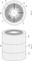
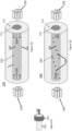
- Figures 1A and 1B show a segmented transmutator vessel 100.
- Figure 1A shows a representative case of axial radial segmentation of the vessel 100 into three (3) vessel sections 100A, 100B and 100C.
- Figure 1B shows a representative cross-section of the radial and azimuthal segmentation of the vessel 100.
- the transmutator vessel 100 in the present embodiment is radially segmented into concentric cylindrical chambers or tanks 102, 104, 106, 108 and 110.
- An azimuthally segmented chamber 107 shows a representative chamber used for either diagnostics or for additional source of neutrons.
- control and localization of various parameters can be increased more easily and/or more precisely, as well as increase the overall transmutator safety by data feedback from various segments via an artificial neural network to control valves to adjust minor actinide concentration. Such precise control optimizes the most minor actinide burned while remaining safe.
- the central tank or chamber 110 is a pressurized gas chamber composed of deuterium or tritium gas and functions as the neutron source to ignite the self-sustaining chain reaction in the first and second concentric tanks 108 and 106.
- the first and second tanks 106 and 108 contain a mixture of FLiBe molten salt and minor actinides.
- the third concentric tank 104 contains fission products that are transmuted into stable or short-lived nuclides.
- the fourth concentric tank 102 is a graphite reflector.
- a mixture of lithium fluoride (LiF) and beryllium fluoride (BeF2) is used as a coolant, a neutron moderator and a solvent of the transuranic elements.
- the salt mixture is composed of 2:1 ratio of LiF to BeF2, hence the stoichiometric compound is given by Li2BeF4.
- this compound is called FLiBe.
- the operation of the transmutator in this liquid state is akin to the molten salt reactor (MSR).
- FLiBe salt has a high heat transfer with capability of carrying the same amount of heat (J/K) as water.
- the heat capacity of FLiBe is 2350 J/(kg-K) while water is 4219 J/(kg-K).
- the density of FLiBe density is about 2 times that of water.
- FLiBe molten-salt remains liquid up to 1430° C without pressurization, providing good safety.
- a pressure water reactor has an operating temperature of 315° C while being held at 150 atmospheres.
- the FliBe salt solidifies at 459° C, providing good safety in case of accident with loss of coolant.
- Fission of TRU elements produces FP (e.g. Tc-99, 1-129, Zr-93 are very long lived and Sr-90, Cs-137 generate almost all radioactivity first 1000 years).
- a transmutation [(n,2n), (n,3n) etc.] of FP using fast (> 1MeV) neutron into stable nuclei is also achieved.
- the outer most tank 102 may be filled with water to control criticality, reactivity and other activities. Further adjustment of criticality may be achieved by replacing the volume of the outer most tank 102 with a neutron reflecting boundary such as, e.g., a graphite neutron reflector.
- a neutron reflecting boundary such as, e.g., a graphite neutron reflector.
- Real-time monitoring of the FLiBe and TRU mixture as well as fission products (FP) in each tank feedbacks the density of TRU and FPs (including real-time injection control of TRU).
- FP fission products
- a reflector e.g. beryllium
- a certain criticality or other conditions i.e., temperature, concentration
- Real-time monitoring of the criticality and other physical parameters is performed in all tanks 108, 106 and 104, and in any additional tank. Data is then feedback into control circuitry which is connected to valves, pumps etc. to maintain preset parameters.
- the neutron generating machine inside the cylindrical tank 110 may be positioned on a rail system to easily slide in and out. In one scenario, the machine remains inside the tank 110. In a second scenario, once the real-time monitoring system establishes that a critical value is reached inside the tanks 108 and 106 with FLiBe/TRU solution, the neutron generator may be withdrawn and reused in a different assembly of tanks 108 and 106.
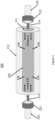
- FIG 2 shows a partial view of a single assembly of a transmutator 200 having a tank 212 filled with a mixture of minor actinides and FLiBe and a neutron source tank 210 positioned therein. Additional tanks, as shown in Figures 1A, 1B may enclose the tank 212.
- a deuteron beam 214 is generated by the electrostatic accelerator 220 (see Figure 6 ) focused by a magnet 222 to pass through an entrance port 211 to the neutron source tank 210.
- the energy of the deuteron beam 214 is in the range of 150-200 keV (at a current of 10 A).
- the deuteron beam 216 then propagates through the pressurized tank 210 filled with tritium or deuterium gas.
- the deuteron beam 216 interacts and fuses with tritium or deuterium producing neutrons 226.
- the neutrons 226 are emitted from the pressurized tank 210 and interact with and incinerate minor actinides in the concentric tank 212.
- FIG 3 shows an alternative embodiment of neutron generation with positive deuteron beams.
- the deuteron beam 214 is created and the deuteron beam 216 propagates within the neutron source tank 210 as described above with regards to the embodiment shown in Figure 2 .
- the deuteron beam 216 propagates within the neutron source tank 210 onto a solid target 228 composed of either titanium-tritium or titanium-deuterium.
- the deuteron beam 216 interacts with either the tritium or deuterium of the solid target 228 to generate fusion neutrons 226.
- the neutrons 226 are emitted from the pressurized tank 210 and interact with and incinerate minor actinides in the concentric tank 212.
- the solid target 228 depicted in Figure 3 is composed of titanium.
- the injected deuteron beam 216 imbeds within the titanium lattice, and any subsequent deuteron beams 216 then interact with the already imbedded deuterons to create fusion neutrons 226.
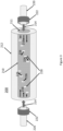
- Figure 4A shows a partial view of an alternative embodiment of a single assembly of a transmutator 200 having a tank 212 filled with a mixture of minor actinides and FLiBe and a neutron source tank 210 positioned therein.
- a plurality of deuteron beams 214 and solid targets 228 are provided with the beams 214 injected from electrostatic accelerators 220 positioned within the neutron source tank 210.
- a single deuteron beam generator 220, deuteron beam 214 and solid target 228 are shown in Figure 4B .
- the deuteron beam 214 interacts with either the tritium or deuterium solid target 228 to generate fusion neutrons 226.
- the neutrons 226 are emitted from the neutron source tank 210 and interact with and incinerate minor actinides in the tank 212 surrounding the source tank 210.
- the solid target 228 depicted in Figures 4A and 4B is composed of titanium.
- the injected deuteron beam 216 imbeds within the titanium lattice, and any subsequent deuteron beams 216 then interact with the already imbedded deuterons to create fusion neutrons 226.
- FIG. 5A shows a partial view of an alternative embodiment of a single assembly of a transmutator 200 having a tank 212 filled with a mixture of minor actinides and FLiBe and a neutron source tank 210 positioned therein.
- a plurality of deuteron beam assemblies 220 are provided with the beams 216 injected external to the neutron source tank 210 filled with pressurized tritium or deuterium gas.
- the deuteron beams 216 are injected into the tank 210 through the entrance port 211 and consequently propagate through the tank 210 where the deuteron beams 216 interact and fuse with the tritium or deuteron gas to generate neutrons 226.
- Figure 5C shows a single beam assembly 220 whereas beam assembly 220 and focusing magnet 222 are shown.
- the focused beam 214 is subsequently injected into the neutron source tank 210 passing through the entrance port 211.
- FIG. 5B shows an alternative embodiment.
- the plurality of beams 216 are injected onto solid targets 228 generating fusion neutrons 226.
- the solid targets 228 are composed of either titanium-tritium or titanium-deuterium.
- the deuteron beam 216 interacts with either tritium or deuterium of the solid target 228 to generate the fusion neutrons 226.
- the neutrons 226 are emitted from the pressurized tank 210 to interact with and incinerate minor actinides in the tank 212 surrounding the pressurized tank 210.
- the solid target 228 depicted in Figure 5B is composed of titanium.
- the injected deuteron beam 216 imbeds within the titanium lattice, and any subsequent deuteron beams 216 then interact with the already imbedded deuterons to create fusion neutrons 226.
- a beam system 220 is based on positive ion multi-aperture extraction sources and utilizes geometric focusing, inertial cooling of the ion extraction grids and differential pumping.
- the beam system 220 includes an RF plasma source 240 at an input end (this can be substituted with an arc source or the like) with a magnetic screen 242 covering the end.
- An ion optical source and acceleration grids 244 are coupled to the plasma source 240 and a gate valve 238 is positioned between the ion optical source and acceleration grids 244 and an aiming device 230 at the exit end.
- a cooling system comprises two cryo-refrigerators 234, two cryopanels 236 and a LN2 shroud. This flexible design allows for operation over a broad range of parameters.
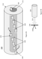
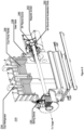
- Figure 7 shows a laser operation system 700 for the purposes of spectroscopy, active monitoring and fission product separation.
- Component A is the CAN laser (in bundles appropriately);
- component B is the modulator /controller of the CAN laser (controlling the laser properties such as the power level, amplitude shape, periods and phases, the relative operations, direction, etc.);
- component C is the laser rays irradiating the solution and solvents in the central tank (see component K) for both the monitoring and separation (or controlling the chemistry of the solvents);
- component D is the solution that contains solvents including the transuraniums (such as Am, Cm, Np) ions that are to be separated and transmuted by the transmutator E [Ref.
- component F is the water that stops the neutrons both from the fusion source, i.e., transmutator E, and from the fission products
- component G is the precipitation that is to be taken out of the deposit at the bottom of the central tank (as an example of a separation by laser chemistry in the central tank where solution is contained)
- component H is the unnecessary deposited elements that are not to be transmuted at this time in this particular tank and to be transferred to another tank, where they will be again in the solution similar to this to be further separated and transmuted
- component I is the feedback ANN circuit and computer that registers and controls the signal of the monitored information such as spectrum of the FP
- component J is the detector of the transmitted CAN laser signals (amplitudes, phases and frequencies, and deflections, etc.)
- component K is the "thin" first wall of the central tank that allow nearly free transmission of the energetic neutrons generated either by fusion or fission in the central tank
- component L is the outer tank with
- Both the central tank K and the outer tank L are equipped with appropriate monitors of the temperature, pressure, and some additional physical and chemical information in addition to the CAN laser monitoring to monitor, and provide alerts regarding, the transmutator's condition to keep the tanks from going over the "board" (such as runaway events) with appropriate safeguards such as the real-timed valves, electrical switches, etc.
- Component Q is a heat exchanger and component M converts heat to electricity.
- the heated solution and water in the central and outer tanks K and L may be maintained in its state by motors (or perhaps appropriate channels inside the tanks, or equivalents) as desired, and excess heat is taken out and converted into electrical (or chemical) energies by component M.
- component P is the pipe (and its valve that controls the flow between the tanks) connecting the segregated separator tank and the transmutator tank.
- Component O is a solving region of the injected separated MA into the transmutator tank. The residual fission products left in component D are transported out through the pipe component R into a storage tank component S.
- the central tank K contains the solution D of the transuraniums that were extracted from the original spent fuel that has been liquefied with proper solutions (such as acids).
- proper solutions such as acids
- U and Pu have been already extracted from the solution D by known processes (such as PUREX).
- the solution D may thus include other elements such as fission products (FPs such as Cs, Sr, I, Zr, Tc, etc.). These elements can tend to absorb neutrons, but not necessarily proliferate neutrons as the transuraniums tend to do.
- FPs fission products
- the FPs need to be eliminated from the solution D in the central tank K by chemical reactions and laser chemistry, etc., with the help of the CAN laser A and other chemical means. If these elements precipitate by the added chemical and/or chemical excitation etc. from the CAN laser, the precipitated components of chemicals may be removed from this central tank K to another tank for the treatment of such elements as the fission products etc.
- the transuraniums (mainly Am, Cm, Np) are irradiated with neutrons from the transmutator E.
- These transuraniums may have different isotopes, but all of them are radioactive isotopes, as they are beyond uranium in their atomic number. Either neutrons from the transmutator E or neutrons arising from the fissions of the transuraniums will contribute to the transmutation of the transuraniums if neutrons are absorbed by these nuclei.
- the transmutator and laser monitor and separator system 800 includes two separate tanks segregating the separation and transmutation processes into two distinct tanks.
- the separator (with laser monitor attached) is on the right, while the transmutator is on the left.
- the two systems are connected by a transmission pipe and valve, component P, which is used to transmit the deposited (or separated) transuraniums (MA) from the separator tank on the right into the transmutator tank on the left.
- the new carrier liquid (component O) preferably only contains (or primarily contains) TA, but not any more fission products that have been separated in the separator tank on the right.
- the central tank D on the left has primarily (or only) MA solution.
- the elements left out of the liquid contain mainly FPs that are transported in a pipe (component R) into a storage tank (component S). Such FPs may be put together into solidified materials for burial treatment.
- a typical nuclear reactor generates the following spent fuel nuclear wastes. [Refs. 22 and 23] Per 1 ton of uranium which generates 50GWd of power. During this operation the nuclear wastes are: about 2.5 kg of transuraniums (Np, Am, Cm) and about 50kg of fission products. The amount of 2.5kg of MA (Minor Actinides, i.e. transuraniums) is about 100mol, approximately 6 x 1025 atoms of MA. This amounts to about 7 x 10²⁰ atoms of MA per second, approximately 1021 MA atoms in 1 sec. This translates into about 1kW of laser power if the absorption of one photon (eV) by each MA atom in order to laser excite each atom is required. Let ⁇ be the efficiency of excitation of an MA atom by 1 photon of laser. Then the power P of the laser to be absorbed by all MA atoms of the above amount per second is P ⁇ 1 / ⁇ kW .
- the high efficiency neutron generation method is applicable to fields and processes requiring neutrons having energy up to 14 MeV, such as, e.g., cancer medical applications such as, e.g., boron-neutron capture therapy (BNCT) and radioisotope generation, structural integrity testing of buildings, bridges, etc., material science and chip testing, oil well logging and the like.
- cancer medical applications such as, e.g., boron-neutron capture therapy (BNCT) and radioisotope generation, structural integrity testing of buildings, bridges, etc., material science and chip testing, oil well logging and the like.
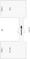
- Two additional embodiments are presented: (1) a first embodiment directed to a 2-tank strategy to reduce the overall neutron cost whereas Tank 1 is critical and Tank 2 subcritical, and (2) second embodiment directed toward a greener, carbon negative trasmutator through the generation of synthetic fuel by the chemical conversion of CO_2 whereas the heat to drive the reaction is generated by fission.
- the transmutator 900 comprises two interconnected sets of tanks referred to as Tank 1 and Tank 2.
- Tanks 1 and 2 which are substantially similar to the tanks depicted in Figures 2A and 3A, may include a tank containing materials to be transmuted and a neutron source tank positioned therein, and as depicted in Figures 1A and 1B , these tanks may be enclosed by additional concentric tanks.
- Tank 1 preferably contains a mixture of Pu and minor actinides (MA) including neptunium, americium and curium (Np, Am, Cm), while Tank 2 contains a mixture of only minor actinides (MA).
- Tank 1 is fueled using the spent nuclear fuel (Pu and MA) after chemical removal of fission products.
- Tank 1 utilizes fast neutrons (fusion neutrons in addition to unmoderated fission neutrons with energy >1 MeV) to transmute the minor actinides (MA) and plutonium (Pu), while the concentration of curium (Cm) is increased.
- fusion neutrons fusion neutrons in addition to unmoderated fission neutrons with energy >1 MeV
- MA minor actinides
- Pu plutonium
- a minor amount of neutrons can be injected into Tank 1 to kick start the incineration of Pu.
- the minor actinides (MA) in Tank 1, now with higher concentration of curium (Cm), may be separated and fed into Tank 2.
- the connected Tank 2 operates in parallel to burn the minor actinides (MA) with the increased concentration of curium (Cm) in a subcritical ( k eff ⁇ 1) operation, as described above. This process provides a path to safely and smoothly burn the entire transuranic spent nuclear fuel (not just MAs) while reducing the number of neutrons required to do so by about a factor of 100x.
- Tank 1 and Tank 2 are real-time monitored by laser and gamma.
- a broadband or a scanning laser is used to monitor the elemental composition of Tank 1 and Tank 2 using the laser induced fluorescence and scattering.
- Gamma monitoring can be either active or passive. Passive gamma monitoring utilizes gamma generated from nuclear decay or transition. Active gamma monitoring utilizes external gamma beam with energy above few MeV and relies on the nuclear resonance fluorescence. Both active and passive monitoring provides information about the isotopic composition of the transmutator fuel.
- Information from the laser and the gamma monitoring is collected and fed into a computer comprising logic adapted to predict and/or control future states of the transmutator by adjusting the refueling of Tank 1 or adjusting the MA concentration in Tank 2.
- a computer comprising logic adapted to predict and/or control future states of the transmutator by adjusting the refueling of Tank 1 or adjusting the MA concentration in Tank 2.
- the fuel in Tank 1 and Tank 2 is dissolved in a molten salt allowing for light propagation.
- Real time monitoring is an integral part of the overall active safety and efficiency of the transmutator whereas a detail knowledge of the transmutator composition will determine the position of the control rods, the refueling and fission product extraction.
- Passive features include molten salt that expands with increasing temperature thus shutting the transmutator down; dump tank separated from the transmutator by a freeze plug whereas any abnormal temperature spike will melt the plug and gravity flow the entire inventory of the transmutator into the dump tank composed of neutron absorbers.
- the walls of Tank 1 and Tank 2 are made of diamond. To protect walls from chemical erosion and corrosion, the salt adjacent to the wall (facing the molten salt) is allowed to solidify preventing direct contact of the molten salt with the walls.
- the transmutator embodiments described above can be applied to the methods and processes of carbon dioxide reduction such as its use as a coolant and its generation of a synthetic fuel to become overall carbon-negative is suggested.
- the synthetic fuel CH 4 - methane
- the synthetic fuel may be generated via CO 2 + 4 H 2 ⁇ CH 4 + 2 H 2 O reaction (Sabatier reaction) requiring 200-400 °C and the presence of a catalyst, e.g., Ni, Cu, Ru.
- the CO 2 may be extracted from the atmosphere, the ocean, or by direct capturing of CO 2 at the source of emission such as automobiles, houses, chimneys and smokestacks.
- the molten salt transmutator operating temperature range is 250 -1200 °C and, thus, is ideally situated to supply continuously the necessary temperature required to drive the Sabatier reaction to produce methane, and provide an effective pathway to stabilize and reduce the CO 2 concentration in the atmosphere and the ocean.
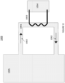
- a partial view of a synthetic fuel generation system 1000 is shown to include a transmutator vessel 1005, a secondary loop pipe 1001, the direction of the flow of the molten salt + TRU 1002, a heat exchanger 1003, and a tank for the Sabatier reaction 1004.
- the heat transfer fluid in the heat exchanger pipe is CO2 which is directly used in the tank 1004.
- the heat exchange pipe of the heat exchanger 2003 of a synthetic fuel generation system 2000 is a closed and independent system, and the transfer fluid may be replaced with a molten salt.
- the synthetic fuel generation system 2000 is shown to include a transmutator vessel 2005, a secondary loop pipe 2001, the direction of the flow of the molten salt + TRU 2002, a heat exchanger 2003, and a tank for the Sabatier reaction 2004.
- Figure 13 shows a partial view of a synthetic fuel generation system 3000 having a transmutator 3005, a heat exchanger 3001, the direction of the flow of the fluid 3002, and a tank for the Sabatier reaction 3003.
- the reactant, CO 2 from the Sabatier reaction is the transfer fluid.
- Figure 14 shows the heat exchanger loop 4001 of a synthetic fuel generation system 4000 as closed and independent loop with the heat transfer fluid being, for example, a molten salt.
- the synthetic fuel generation system 4000 is shown to include a transmutator 4005, a heat exchanger 4001, the direction of the flow of the fluid 4002, and a tank for the Sabatier reaction 4003.
- ionizing radiation originating within the transmutator and carried by the molten salt is utilized as a 1-10s eV energy source to enable various chemical reactions.
- the 1-10 eV energy source enables, for example, the production of ammonia and conversion of CO_2+CH_4 ⁇ CH_3 COOH.
- Processing circuitry for use with embodiments of the present disclosure can include one or more computers, processors, microprocessors, controllers, and/or microcontrollers, each of which can be a discrete chip or distributed amongst (and a portion of) a number of different chips.
- Processing circuitry for use with embodiments of the present disclosure can include a digital signal processor, which can be implemented in hardware and/or software of the processing circuitry for use with embodiments of the present disclosure.
- a DSP is a discrete semiconductor chip.
- Processing circuitry for use with embodiments of the present disclosure can be communicatively coupled with the other components of the figures herein.
- Processing circuitry for use with embodiments of the present disclosure can execute software instructions stored on memory that cause the processing circuitry to take a host of different actions and control the other components in figures herein.
- Processing circuitry for use with embodiments of the present disclosure can also perform other software and/or hardware routines.
- processing circuitry for use with embodiments of the present disclosure can interface with communication circuitry and perform analog-to-digital conversions, encoding and decoding, other digital signal processing and other functions that facilitate the conversion of voice, video, and data signals into a format (e.g., in-phase and quadrature) suitable for provision to communication circuitry, and can cause communication circuitry to transmit the RF signals wirelessly over links.
- a format e.g., in-phase and quadrature
- Communication circuitry for use with embodiments of the present disclosure can be implemented as one or more chips and/or components (e.g., transmitter, receiver, transceiver, and/or other communication circuitry) that perform wireless communications over links under the appropriate protocol (e.g., Wi-Fi, Bluetooth, Bluetooth Low Energy, Near Field Communication (NFC), Radio Frequency Identification (RFID), proprietary protocols, and others.
- One or more other antennas can be included with communication circuitry as needed to operate with the various protocols and circuits.
- communication circuitry for use with embodiments of the present disclosure can share an antenna for transmission over links.
- Processing circuitry for use with embodiments of the present disclosure can also interface with communication circuitry to perform the reverse functions necessary to receive a wireless transmission and convert it into digital data, voice, and video.
- RF communication circuitry can include a transmitter and a receiver (e.g., integrated as a transceiver) and associated encoder logic.
- a reader can also include communication circuitry and interfaces for wired communication (e.g., a USB port, etc.) as well as circuitry for determining the geographic position of reader device (e.g., global positioning system (GPS) hardware).
- GPS global positioning system
- Processing circuitry for use with embodiments of the present disclosure can also be adapted to execute the operating system and any software applications that reside on a reader device, process video and graphics, and perform those other functions not related to the processing of communications transmitted and received.
- Any number of applications can be executed by processing circuitry on a dedicated or mobile phone reader device at any one time, and may include one or more applications that are related to a diabetes monitoring regime, in addition to the other commonly used applications, e.g., smart phone apps that are unrelated to such a regime like email, calendar, weather, sports, games, etc.
- Memory for use with embodiments of the present disclosure can be shared by one or more of the various functional units present within a reader device, or can be distributed amongst two or more of them (e.g., as separate memories present within different chips). Memory can also be a separate chip of its own. Memory can be non-transitory, and can be volatile (e.g., RAM, etc.) and/or non-volatile memory (e.g., ROM, flash memory, F-RAM, etc.).
- volatile e.g., RAM, etc.
- non-volatile memory e.g., ROM, flash memory, F-RAM, etc.
- Computer program instructions for carrying out operations in accordance with the described subject matter may be written in any combination of one or more programming languages, including an object oriented programming language such as Java, JavaScript, Smalltalk, C++, C#, Transact-SQL, XML, PHP or the like and conventional procedural programming languages, such as the "C" programming language or similar programming languages.
- the program instructions may execute entirely on the user's computing device (e.g., reader) or partly on the user's computing device.
- the program instructions may reside partly on the user's computing device and partly on a remote computing device or entirely on the remote computing device or server, e.g., for instances where the identified frequency is uploaded to the remote location for processing.
- the remote computing device may be connected to the user's computing device through any type of network, or the connection may be made to an external computer.
Landscapes
- Physics & Mathematics (AREA)
- Engineering & Computer Science (AREA)
- High Energy & Nuclear Physics (AREA)
- General Engineering & Computer Science (AREA)
- Chemical & Material Sciences (AREA)
- Chemical Kinetics & Catalysis (AREA)
- General Chemical & Material Sciences (AREA)
- Spectroscopy & Molecular Physics (AREA)
- Plasma & Fusion (AREA)
- Optics & Photonics (AREA)
- Particle Accelerators (AREA)
Applications Claiming Priority (3)
| Application Number | Priority Date | Filing Date | Title |
|---|---|---|---|
| US201862727418P | 2018-09-05 | 2018-09-05 | |
| US201962876979P | 2019-07-22 | 2019-07-22 | |
| PCT/US2019/049824 WO2020051380A1 (en) | 2018-09-05 | 2019-09-05 | Systems and methods for electrostatic accelerator driven neutron generation for a liquid-phase based transmutation |
Publications (3)
| Publication Number | Publication Date |
|---|---|
| EP3847672A1 EP3847672A1 (en) | 2021-07-14 |
| EP3847672A4 EP3847672A4 (en) | 2022-06-01 |
| EP3847672B1 true EP3847672B1 (en) | 2024-10-23 |
Family
ID=69723251
Family Applications (1)
| Application Number | Title | Priority Date | Filing Date |
|---|---|---|---|
| EP19857901.3A Active EP3847672B1 (en) | 2018-09-05 | 2019-09-05 | Systems and methods for electrostatic accelerator driven neutron generation for a liquid-phase based transmutation |
Country Status (8)
| Country | Link |
|---|---|
| US (1) | US11901095B2 (enExample) |
| EP (1) | EP3847672B1 (enExample) |
| JP (1) | JP2022502673A (enExample) |
| KR (1) | KR102893738B1 (enExample) |
| CN (1) | CN112912970A (enExample) |
| AU (1) | AU2019335375A1 (enExample) |
| CA (1) | CA3112379A1 (enExample) |
| WO (1) | WO2020051380A1 (enExample) |
Families Citing this family (1)
| Publication number | Priority date | Publication date | Assignee | Title |
|---|---|---|---|---|
| PL3187028T3 (pl) * | 2014-10-13 | 2020-06-29 | Tae Technologies, Inc. | Układ łączenia i kompresji zwartych torusów |
Family Cites Families (16)
| Publication number | Priority date | Publication date | Assignee | Title |
|---|---|---|---|---|
| US5541947A (en) | 1995-05-10 | 1996-07-30 | The Regents Of The University Of Michigan | Selectively triggered, high contrast laser |
| HU226177B1 (en) * | 2001-09-20 | 2008-06-30 | Budapesti Mueszaki Es Gazdasag | Method for transmutation of radioactive wastes |
| US6867419B2 (en) | 2002-03-29 | 2005-03-15 | The Regents Of The University Of California | Laser driven compact ion accelerator |
| CN1279547C (zh) * | 2003-08-26 | 2006-10-11 | 中国科学院等离子体物理研究所 | 基于可裂变材料中子增殖的次临界核废料处理与核燃料生产的方法和系统 |
| EP1754232B1 (en) * | 2004-05-30 | 2013-06-26 | Pebble Bed Modular Reactor (Proprietary) Limited | Method of treating radioactive waste |
| JP2009518646A (ja) | 2005-12-05 | 2009-05-07 | セルドン テクノロジーズ,インコーポレイテッド | ナノチューブを使用してエネルギー粒子を発生させる方法、及びその物品 |
| CN1945751B (zh) * | 2006-11-21 | 2010-05-12 | 中国原子能科学研究院 | 加速器驱动的快-热耦合次临界反应堆 |
| US8440165B2 (en) | 2007-03-29 | 2013-05-14 | Npl Associates, Inc. | Dislocation site density techniques |
| US8461516B2 (en) * | 2007-10-16 | 2013-06-11 | Dent International Research, Inc. | Apparatus and process for generating a neutron beam |
| US10332646B2 (en) * | 2011-12-05 | 2019-06-25 | Wisconsin Alumni Research Foundation | Apparatus and method for generating medical isotopes |
| CN102623078A (zh) * | 2012-03-30 | 2012-08-01 | 中国科学院合肥物质科学研究院 | 一种基于混合能谱的高效核废料嬗变次临界堆芯 |
| US9368244B2 (en) * | 2013-09-16 | 2016-06-14 | Robert Daniel Woolley | Hybrid molten salt reactor with energetic neutron source |
| US20150098544A1 (en) * | 2013-10-09 | 2015-04-09 | Anatoly Blanovsky | Sustainable Modular Transmutation Reactor |
| US10504630B2 (en) * | 2014-01-22 | 2019-12-10 | Robert F. Bodi | Method and system for generating electricity using waste nuclear fuel |
| JP6789539B2 (ja) * | 2016-08-05 | 2020-11-25 | 株式会社八神製作所 | 中性子発生装置用のターゲット |
| CN108470589B (zh) * | 2018-05-02 | 2024-05-17 | 中国科学技术大学 | 一种可同时嬗变次锕系核素和长寿命裂变产物的快热混合能谱临界堆芯 |
-
2019
- 2019-09-05 JP JP2021524144A patent/JP2022502673A/ja not_active Ceased
- 2019-09-05 EP EP19857901.3A patent/EP3847672B1/en active Active
- 2019-09-05 CN CN201980072907.XA patent/CN112912970A/zh active Pending
- 2019-09-05 WO PCT/US2019/049824 patent/WO2020051380A1/en not_active Ceased
- 2019-09-05 KR KR1020217009006A patent/KR102893738B1/ko active Active
- 2019-09-05 CA CA3112379A patent/CA3112379A1/en active Pending
- 2019-09-05 AU AU2019335375A patent/AU2019335375A1/en not_active Abandoned
-
2021
- 2021-03-05 US US17/193,973 patent/US11901095B2/en active Active
Also Published As
| Publication number | Publication date |
|---|---|
| AU2019335375A1 (en) | 2021-04-22 |
| KR20210048532A (ko) | 2021-05-03 |
| CA3112379A1 (en) | 2020-03-12 |
| US20210358650A1 (en) | 2021-11-18 |
| KR102893738B1 (ko) | 2025-11-28 |
| EP3847672A4 (en) | 2022-06-01 |
| EP3847672A1 (en) | 2021-07-14 |
| WO2020051380A1 (en) | 2020-03-12 |
| CN112912970A (zh) | 2021-06-04 |
| JP2022502673A (ja) | 2022-01-11 |
| US11901095B2 (en) | 2024-02-13 |
Similar Documents
| Publication | Publication Date | Title |
|---|---|---|
| Abderrahim et al. | Accelerator and target technology for accelerator driven transmutation and energy production | |
| Stanculescu | Accelerator driven systems (ADSs) for nuclear transmutation | |
| Abderrahim et al. | Transmutation of high‐level nuclear waste by means of accelerator driven system | |
| Aït Abderrahim | Realization of a new large research infrastructure in Belgium: MYRRHA contribution for closing the nuclear fuel cycle making nuclear energy sustainable | |
| US20210358649A1 (en) | Systems and methods for laser driven neutron generation for a liquid-phase based transmutation | |
| US11901095B2 (en) | System for electrostatic accelerator driven neutron generation for a liquid-phase based transmutation of radioactive transuranic waste | |
| Takahashi et al. | Concepts of accelerator based transmutation systems | |
| WO2000072329A2 (en) | Apparatus for generating power from fission of spent nuclear waste | |
| Moir et al. | Fusion–Fission Hybrid Reactors | |
| Seltborg | External source effects and neutronics in accelerator-driven systems | |
| HK40044964A (en) | Systems and methods for electrostatic accelerator driven neutron generation for a liquid-phase based transmutation | |
| Bhowmik et al. | Partitioning and transmutation of used nuclear fuel in support of geological waste disposal | |
| Eriksson | Accelerator-driven systems: safety and kinetics | |
| Pudjorahardjo et al. | High power particle accelerator for driving the nuclear waste transmutation system at nuclear power plant | |
| Bowman et al. | GEM* STAR: The Alternative Reactor Technology Comprising Graphite, Molten Salt, and Accelerators | |
| Wigeland et al. | AFCI Options Study | |
| JPWO2020051380A5 (enExample) | ||
| EA040189B1 (ru) | Системы и способы для приводимой в действие лазером генерации нейтронов для трансмутации на основе жидкой фазы | |
| Tahar | High power ring methods and accelerator driven subcritical reactor application | |
| HK40055093A (en) | Systems and methods for laser driven neutron generation for a liquid-phase based transmutation | |
| Browne et al. | Accelerator-driven transmutation of waste | |
| Wimmers et al. | Nuclear Physics and Reactor Technologies (Fission and Fusion) | |
| JPWO2020051376A5 (enExample) | ||
| Salvatores et al. | Challenges and potential benefits of partitioning and transmutation (P&T) | |
| Handa | Nuclear Waste and Power Generation |
Legal Events
| Date | Code | Title | Description |
|---|---|---|---|
| STAA | Information on the status of an ep patent application or granted ep patent |
Free format text: STATUS: THE INTERNATIONAL PUBLICATION HAS BEEN MADE |
|
| PUAI | Public reference made under article 153(3) epc to a published international application that has entered the european phase |
Free format text: ORIGINAL CODE: 0009012 |
|
| STAA | Information on the status of an ep patent application or granted ep patent |
Free format text: STATUS: REQUEST FOR EXAMINATION WAS MADE |
|
| 17P | Request for examination filed |
Effective date: 20210315 |
|
| AK | Designated contracting states |
Kind code of ref document: A1 Designated state(s): AL AT BE BG CH CY CZ DE DK EE ES FI FR GB GR HR HU IE IS IT LI LT LU LV MC MK MT NL NO PL PT RO RS SE SI SK SM TR |
|
| DAV | Request for validation of the european patent (deleted) | ||
| DAX | Request for extension of the european patent (deleted) | ||
| REG | Reference to a national code |
Ref legal event code: R079 Ipc: G21G0001080000 Ref country code: DE Ref document number: 602019060901 Country of ref document: DE Free format text: PREVIOUS MAIN CLASS: G21C0001280000 |
|
| A4 | Supplementary search report drawn up and despatched |
Effective date: 20220503 |
|
| RIC1 | Information provided on ipc code assigned before grant |
Ipc: G21G 1/06 20060101ALI20220427BHEP Ipc: G21C 1/28 20060101ALI20220427BHEP Ipc: G21G 1/08 20060101AFI20220427BHEP |
|
| P01 | Opt-out of the competence of the unified patent court (upc) registered |
Effective date: 20230519 |
|
| RIC1 | Information provided on ipc code assigned before grant |
Ipc: G21G 1/06 20060101ALI20240318BHEP Ipc: G21C 1/28 20060101ALI20240318BHEP Ipc: G21G 1/08 20060101AFI20240318BHEP |
|
| GRAP | Despatch of communication of intention to grant a patent |
Free format text: ORIGINAL CODE: EPIDOSNIGR1 |
|
| STAA | Information on the status of an ep patent application or granted ep patent |
Free format text: STATUS: GRANT OF PATENT IS INTENDED |
|
| INTG | Intention to grant announced |
Effective date: 20240514 |
|
| GRAS | Grant fee paid |
Free format text: ORIGINAL CODE: EPIDOSNIGR3 |
|
| GRAA | (expected) grant |
Free format text: ORIGINAL CODE: 0009210 |
|
| STAA | Information on the status of an ep patent application or granted ep patent |
Free format text: STATUS: THE PATENT HAS BEEN GRANTED |
|
| AK | Designated contracting states |
Kind code of ref document: B1 Designated state(s): AL AT BE BG CH CY CZ DE DK EE ES FI FR GB GR HR HU IE IS IT LI LT LU LV MC MK MT NL NO PL PT RO RS SE SI SK SM TR |
|
| REG | Reference to a national code |
Ref country code: GB Ref legal event code: FG4D |
|
| REG | Reference to a national code |
Ref country code: CH Ref legal event code: EP |
|
| REG | Reference to a national code |
Ref country code: DE Ref legal event code: R096 Ref document number: 602019060901 Country of ref document: DE |
|
| REG | Reference to a national code |
Ref country code: IE Ref legal event code: FG4D |
|
| REG | Reference to a national code |
Ref country code: LT Ref legal event code: MG9D |
|
| REG | Reference to a national code |
Ref country code: NL Ref legal event code: MP Effective date: 20241023 |
|
| REG | Reference to a national code |
Ref country code: AT Ref legal event code: MK05 Ref document number: 1735544 Country of ref document: AT Kind code of ref document: T Effective date: 20241023 |
|
| PG25 | Lapsed in a contracting state [announced via postgrant information from national office to epo] |
Ref country code: NL Free format text: LAPSE BECAUSE OF FAILURE TO SUBMIT A TRANSLATION OF THE DESCRIPTION OR TO PAY THE FEE WITHIN THE PRESCRIBED TIME-LIMIT Effective date: 20241023 |
|
| PG25 | Lapsed in a contracting state [announced via postgrant information from national office to epo] |
Ref country code: NL Free format text: LAPSE BECAUSE OF FAILURE TO SUBMIT A TRANSLATION OF THE DESCRIPTION OR TO PAY THE FEE WITHIN THE PRESCRIBED TIME-LIMIT Effective date: 20241023 |
|
| PG25 | Lapsed in a contracting state [announced via postgrant information from national office to epo] |
Ref country code: PT Free format text: LAPSE BECAUSE OF FAILURE TO SUBMIT A TRANSLATION OF THE DESCRIPTION OR TO PAY THE FEE WITHIN THE PRESCRIBED TIME-LIMIT Effective date: 20250224 Ref country code: IS Free format text: LAPSE BECAUSE OF FAILURE TO SUBMIT A TRANSLATION OF THE DESCRIPTION OR TO PAY THE FEE WITHIN THE PRESCRIBED TIME-LIMIT Effective date: 20250223 Ref country code: HR Free format text: LAPSE BECAUSE OF FAILURE TO SUBMIT A TRANSLATION OF THE DESCRIPTION OR TO PAY THE FEE WITHIN THE PRESCRIBED TIME-LIMIT Effective date: 20241023 |
|
| PG25 | Lapsed in a contracting state [announced via postgrant information from national office to epo] |
Ref country code: FI Free format text: LAPSE BECAUSE OF FAILURE TO SUBMIT A TRANSLATION OF THE DESCRIPTION OR TO PAY THE FEE WITHIN THE PRESCRIBED TIME-LIMIT Effective date: 20241023 |
|
| PG25 | Lapsed in a contracting state [announced via postgrant information from national office to epo] |
Ref country code: BG Free format text: LAPSE BECAUSE OF FAILURE TO SUBMIT A TRANSLATION OF THE DESCRIPTION OR TO PAY THE FEE WITHIN THE PRESCRIBED TIME-LIMIT Effective date: 20241023 |
|
| PG25 | Lapsed in a contracting state [announced via postgrant information from national office to epo] |
Ref country code: ES Free format text: LAPSE BECAUSE OF FAILURE TO SUBMIT A TRANSLATION OF THE DESCRIPTION OR TO PAY THE FEE WITHIN THE PRESCRIBED TIME-LIMIT Effective date: 20241023 |
|
| PG25 | Lapsed in a contracting state [announced via postgrant information from national office to epo] |
Ref country code: NO Free format text: LAPSE BECAUSE OF FAILURE TO SUBMIT A TRANSLATION OF THE DESCRIPTION OR TO PAY THE FEE WITHIN THE PRESCRIBED TIME-LIMIT Effective date: 20250123 |
|
| PG25 | Lapsed in a contracting state [announced via postgrant information from national office to epo] |
Ref country code: LV Free format text: LAPSE BECAUSE OF FAILURE TO SUBMIT A TRANSLATION OF THE DESCRIPTION OR TO PAY THE FEE WITHIN THE PRESCRIBED TIME-LIMIT Effective date: 20241023 Ref country code: AT Free format text: LAPSE BECAUSE OF FAILURE TO SUBMIT A TRANSLATION OF THE DESCRIPTION OR TO PAY THE FEE WITHIN THE PRESCRIBED TIME-LIMIT Effective date: 20241023 Ref country code: GR Free format text: LAPSE BECAUSE OF FAILURE TO SUBMIT A TRANSLATION OF THE DESCRIPTION OR TO PAY THE FEE WITHIN THE PRESCRIBED TIME-LIMIT Effective date: 20250124 |
|
| PG25 | Lapsed in a contracting state [announced via postgrant information from national office to epo] |
Ref country code: PL Free format text: LAPSE BECAUSE OF FAILURE TO SUBMIT A TRANSLATION OF THE DESCRIPTION OR TO PAY THE FEE WITHIN THE PRESCRIBED TIME-LIMIT Effective date: 20241023 |
|
| PG25 | Lapsed in a contracting state [announced via postgrant information from national office to epo] |
Ref country code: RS Free format text: LAPSE BECAUSE OF FAILURE TO SUBMIT A TRANSLATION OF THE DESCRIPTION OR TO PAY THE FEE WITHIN THE PRESCRIBED TIME-LIMIT Effective date: 20250123 |
|
| PG25 | Lapsed in a contracting state [announced via postgrant information from national office to epo] |
Ref country code: SM Free format text: LAPSE BECAUSE OF FAILURE TO SUBMIT A TRANSLATION OF THE DESCRIPTION OR TO PAY THE FEE WITHIN THE PRESCRIBED TIME-LIMIT Effective date: 20241023 |
|
| PG25 | Lapsed in a contracting state [announced via postgrant information from national office to epo] |
Ref country code: DK Free format text: LAPSE BECAUSE OF FAILURE TO SUBMIT A TRANSLATION OF THE DESCRIPTION OR TO PAY THE FEE WITHIN THE PRESCRIBED TIME-LIMIT Effective date: 20241023 |
|
| PG25 | Lapsed in a contracting state [announced via postgrant information from national office to epo] |
Ref country code: EE Free format text: LAPSE BECAUSE OF FAILURE TO SUBMIT A TRANSLATION OF THE DESCRIPTION OR TO PAY THE FEE WITHIN THE PRESCRIBED TIME-LIMIT Effective date: 20241023 |
|
| PG25 | Lapsed in a contracting state [announced via postgrant information from national office to epo] |
Ref country code: RO Free format text: LAPSE BECAUSE OF FAILURE TO SUBMIT A TRANSLATION OF THE DESCRIPTION OR TO PAY THE FEE WITHIN THE PRESCRIBED TIME-LIMIT Effective date: 20241023 |
|
| REG | Reference to a national code |
Ref country code: DE Ref legal event code: R097 Ref document number: 602019060901 Country of ref document: DE |
|
| PG25 | Lapsed in a contracting state [announced via postgrant information from national office to epo] |
Ref country code: SK Free format text: LAPSE BECAUSE OF FAILURE TO SUBMIT A TRANSLATION OF THE DESCRIPTION OR TO PAY THE FEE WITHIN THE PRESCRIBED TIME-LIMIT Effective date: 20241023 |
|
| PG25 | Lapsed in a contracting state [announced via postgrant information from national office to epo] |
Ref country code: CZ Free format text: LAPSE BECAUSE OF FAILURE TO SUBMIT A TRANSLATION OF THE DESCRIPTION OR TO PAY THE FEE WITHIN THE PRESCRIBED TIME-LIMIT Effective date: 20241023 |
|
| PG25 | Lapsed in a contracting state [announced via postgrant information from national office to epo] |
Ref country code: IT Free format text: LAPSE BECAUSE OF FAILURE TO SUBMIT A TRANSLATION OF THE DESCRIPTION OR TO PAY THE FEE WITHIN THE PRESCRIBED TIME-LIMIT Effective date: 20241023 |
|
| PLBE | No opposition filed within time limit |
Free format text: ORIGINAL CODE: 0009261 |
|
| STAA | Information on the status of an ep patent application or granted ep patent |
Free format text: STATUS: NO OPPOSITION FILED WITHIN TIME LIMIT |
|
| PG25 | Lapsed in a contracting state [announced via postgrant information from national office to epo] |
Ref country code: SE Free format text: LAPSE BECAUSE OF FAILURE TO SUBMIT A TRANSLATION OF THE DESCRIPTION OR TO PAY THE FEE WITHIN THE PRESCRIBED TIME-LIMIT Effective date: 20241023 |
|
| 26N | No opposition filed |
Effective date: 20250724 |