EP3847342B1 - Boîtier d'alimentation en air sous pression d'un dispositif de refroidissement par jets d'air - Google Patents
Boîtier d'alimentation en air sous pression d'un dispositif de refroidissement par jets d'air Download PDFInfo
- Publication number
- EP3847342B1 EP3847342B1 EP19783592.9A EP19783592A EP3847342B1 EP 3847342 B1 EP3847342 B1 EP 3847342B1 EP 19783592 A EP19783592 A EP 19783592A EP 3847342 B1 EP3847342 B1 EP 3847342B1
- Authority
- EP
- European Patent Office
- Prior art keywords
- air
- outlet
- duct
- air supply
- supply unit
- Prior art date
- Legal status (The legal status is an assumption and is not a legal conclusion. Google has not performed a legal analysis and makes no representation as to the accuracy of the status listed.)
- Active
Links
- 238000001816 cooling Methods 0.000 title claims description 48
- 238000005192 partition Methods 0.000 claims description 29
- 238000004519 manufacturing process Methods 0.000 claims description 25
- 238000009826 distribution Methods 0.000 claims description 24
- 239000000843 powder Substances 0.000 claims description 18
- 239000000654 additive Substances 0.000 claims description 14
- 230000000996 additive effect Effects 0.000 claims description 14
- 238000005304 joining Methods 0.000 claims description 9
- 239000000463 material Substances 0.000 claims description 7
- 241000446313 Lamella Species 0.000 claims description 3
- 238000000151 deposition Methods 0.000 claims description 3
- 230000004927 fusion Effects 0.000 claims description 2
- 208000031968 Cadaver Diseases 0.000 description 25
- 238000010276 construction Methods 0.000 description 7
- 238000002844 melting Methods 0.000 description 3
- 230000008018 melting Effects 0.000 description 3
- 238000000034 method Methods 0.000 description 3
- 229920000297 Rayon Polymers 0.000 description 2
- 210000003323 beak Anatomy 0.000 description 2
- 238000004891 communication Methods 0.000 description 2
- 230000004907 flux Effects 0.000 description 2
- 239000002964 rayon Substances 0.000 description 2
- 238000012550 audit Methods 0.000 description 1
- 238000005516 engineering process Methods 0.000 description 1
- 239000012530 fluid Substances 0.000 description 1
- 239000000446 fuel Substances 0.000 description 1
- 229910000816 inconels 718 Inorganic materials 0.000 description 1
- 238000003754 machining Methods 0.000 description 1
- 238000012423 maintenance Methods 0.000 description 1
- 239000002184 metal Substances 0.000 description 1
- 229910052751 metal Inorganic materials 0.000 description 1
- 238000009423 ventilation Methods 0.000 description 1
- 238000003466 welding Methods 0.000 description 1
Images


Classifications
-
- F—MECHANICAL ENGINEERING; LIGHTING; HEATING; WEAPONS; BLASTING
- F01—MACHINES OR ENGINES IN GENERAL; ENGINE PLANTS IN GENERAL; STEAM ENGINES
- F01D—NON-POSITIVE DISPLACEMENT MACHINES OR ENGINES, e.g. STEAM TURBINES
- F01D25/00—Component parts, details, or accessories, not provided for in, or of interest apart from, other groups
- F01D25/08—Cooling; Heating; Heat-insulation
- F01D25/14—Casings modified therefor
-
- F—MECHANICAL ENGINEERING; LIGHTING; HEATING; WEAPONS; BLASTING
- F02—COMBUSTION ENGINES; HOT-GAS OR COMBUSTION-PRODUCT ENGINE PLANTS
- F02C—GAS-TURBINE PLANTS; AIR INTAKES FOR JET-PROPULSION PLANTS; CONTROLLING FUEL SUPPLY IN AIR-BREATHING JET-PROPULSION PLANTS
- F02C7/00—Features, components parts, details or accessories, not provided for in, or of interest apart form groups F02C1/00 - F02C6/00; Air intakes for jet-propulsion plants
- F02C7/12—Cooling of plants
- F02C7/16—Cooling of plants characterised by cooling medium
- F02C7/18—Cooling of plants characterised by cooling medium the medium being gaseous, e.g. air
-
- F—MECHANICAL ENGINEERING; LIGHTING; HEATING; WEAPONS; BLASTING
- F01—MACHINES OR ENGINES IN GENERAL; ENGINE PLANTS IN GENERAL; STEAM ENGINES
- F01D—NON-POSITIVE DISPLACEMENT MACHINES OR ENGINES, e.g. STEAM TURBINES
- F01D11/00—Preventing or minimising internal leakage of working-fluid, e.g. between stages
- F01D11/08—Preventing or minimising internal leakage of working-fluid, e.g. between stages for sealing space between rotor blade tips and stator
- F01D11/14—Adjusting or regulating tip-clearance, i.e. distance between rotor-blade tips and stator casing
- F01D11/20—Actively adjusting tip-clearance
- F01D11/24—Actively adjusting tip-clearance by selectively cooling-heating stator or rotor components
-
- F—MECHANICAL ENGINEERING; LIGHTING; HEATING; WEAPONS; BLASTING
- F01—MACHINES OR ENGINES IN GENERAL; ENGINE PLANTS IN GENERAL; STEAM ENGINES
- F01D—NON-POSITIVE DISPLACEMENT MACHINES OR ENGINES, e.g. STEAM TURBINES
- F01D25/00—Component parts, details, or accessories, not provided for in, or of interest apart from, other groups
- F01D25/08—Cooling; Heating; Heat-insulation
- F01D25/12—Cooling
-
- F—MECHANICAL ENGINEERING; LIGHTING; HEATING; WEAPONS; BLASTING
- F01—MACHINES OR ENGINES IN GENERAL; ENGINE PLANTS IN GENERAL; STEAM ENGINES
- F01D—NON-POSITIVE DISPLACEMENT MACHINES OR ENGINES, e.g. STEAM TURBINES
- F01D25/00—Component parts, details, or accessories, not provided for in, or of interest apart from, other groups
- F01D25/24—Casings; Casing parts, e.g. diaphragms, casing fastenings
- F01D25/243—Flange connections; Bolting arrangements
-
- F—MECHANICAL ENGINEERING; LIGHTING; HEATING; WEAPONS; BLASTING
- F05—INDEXING SCHEMES RELATING TO ENGINES OR PUMPS IN VARIOUS SUBCLASSES OF CLASSES F01-F04
- F05D—INDEXING SCHEME FOR ASPECTS RELATING TO NON-POSITIVE-DISPLACEMENT MACHINES OR ENGINES, GAS-TURBINES OR JET-PROPULSION PLANTS
- F05D2220/00—Application
- F05D2220/30—Application in turbines
- F05D2220/32—Application in turbines in gas turbines
- F05D2220/323—Application in turbines in gas turbines for aircraft propulsion, e.g. jet engines
-
- F—MECHANICAL ENGINEERING; LIGHTING; HEATING; WEAPONS; BLASTING
- F05—INDEXING SCHEMES RELATING TO ENGINES OR PUMPS IN VARIOUS SUBCLASSES OF CLASSES F01-F04
- F05D—INDEXING SCHEME FOR ASPECTS RELATING TO NON-POSITIVE-DISPLACEMENT MACHINES OR ENGINES, GAS-TURBINES OR JET-PROPULSION PLANTS
- F05D2230/00—Manufacture
- F05D2230/30—Manufacture with deposition of material
- F05D2230/31—Layer deposition
-
- F—MECHANICAL ENGINEERING; LIGHTING; HEATING; WEAPONS; BLASTING
- F05—INDEXING SCHEMES RELATING TO ENGINES OR PUMPS IN VARIOUS SUBCLASSES OF CLASSES F01-F04
- F05D—INDEXING SCHEME FOR ASPECTS RELATING TO NON-POSITIVE-DISPLACEMENT MACHINES OR ENGINES, GAS-TURBINES OR JET-PROPULSION PLANTS
- F05D2230/00—Manufacture
- F05D2230/50—Building or constructing in particular ways
- F05D2230/53—Building or constructing in particular ways by integrally manufacturing a component, e.g. by milling from a billet or one piece construction
-
- F—MECHANICAL ENGINEERING; LIGHTING; HEATING; WEAPONS; BLASTING
- F05—INDEXING SCHEMES RELATING TO ENGINES OR PUMPS IN VARIOUS SUBCLASSES OF CLASSES F01-F04
- F05D—INDEXING SCHEME FOR ASPECTS RELATING TO NON-POSITIVE-DISPLACEMENT MACHINES OR ENGINES, GAS-TURBINES OR JET-PROPULSION PLANTS
- F05D2250/00—Geometry
- F05D2250/10—Two-dimensional
- F05D2250/17—Two-dimensional hyperbolic
-
- F—MECHANICAL ENGINEERING; LIGHTING; HEATING; WEAPONS; BLASTING
- F05—INDEXING SCHEMES RELATING TO ENGINES OR PUMPS IN VARIOUS SUBCLASSES OF CLASSES F01-F04
- F05D—INDEXING SCHEME FOR ASPECTS RELATING TO NON-POSITIVE-DISPLACEMENT MACHINES OR ENGINES, GAS-TURBINES OR JET-PROPULSION PLANTS
- F05D2250/00—Geometry
- F05D2250/20—Three-dimensional
- F05D2250/26—Three-dimensional paraboloid
-
- F—MECHANICAL ENGINEERING; LIGHTING; HEATING; WEAPONS; BLASTING
- F05—INDEXING SCHEMES RELATING TO ENGINES OR PUMPS IN VARIOUS SUBCLASSES OF CLASSES F01-F04
- F05D—INDEXING SCHEME FOR ASPECTS RELATING TO NON-POSITIVE-DISPLACEMENT MACHINES OR ENGINES, GAS-TURBINES OR JET-PROPULSION PLANTS
- F05D2250/00—Geometry
- F05D2250/70—Shape
- F05D2250/75—Shape given by its similarity to a letter, e.g. T-shaped
-
- F—MECHANICAL ENGINEERING; LIGHTING; HEATING; WEAPONS; BLASTING
- F05—INDEXING SCHEMES RELATING TO ENGINES OR PUMPS IN VARIOUS SUBCLASSES OF CLASSES F01-F04
- F05D—INDEXING SCHEME FOR ASPECTS RELATING TO NON-POSITIVE-DISPLACEMENT MACHINES OR ENGINES, GAS-TURBINES OR JET-PROPULSION PLANTS
- F05D2260/00—Function
- F05D2260/20—Heat transfer, e.g. cooling
- F05D2260/201—Heat transfer, e.g. cooling by impingement of a fluid
-
- F—MECHANICAL ENGINEERING; LIGHTING; HEATING; WEAPONS; BLASTING
- F05—INDEXING SCHEMES RELATING TO ENGINES OR PUMPS IN VARIOUS SUBCLASSES OF CLASSES F01-F04
- F05D—INDEXING SCHEME FOR ASPECTS RELATING TO NON-POSITIVE-DISPLACEMENT MACHINES OR ENGINES, GAS-TURBINES OR JET-PROPULSION PLANTS
- F05D2260/00—Function
- F05D2260/20—Heat transfer, e.g. cooling
- F05D2260/232—Heat transfer, e.g. cooling characterized by the cooling medium
-
- Y—GENERAL TAGGING OF NEW TECHNOLOGICAL DEVELOPMENTS; GENERAL TAGGING OF CROSS-SECTIONAL TECHNOLOGIES SPANNING OVER SEVERAL SECTIONS OF THE IPC; TECHNICAL SUBJECTS COVERED BY FORMER USPC CROSS-REFERENCE ART COLLECTIONS [XRACs] AND DIGESTS
- Y02—TECHNOLOGIES OR APPLICATIONS FOR MITIGATION OR ADAPTATION AGAINST CLIMATE CHANGE
- Y02T—CLIMATE CHANGE MITIGATION TECHNOLOGIES RELATED TO TRANSPORTATION
- Y02T50/00—Aeronautics or air transport
- Y02T50/60—Efficient propulsion technologies, e.g. for aircraft
Definitions
- the invention lies in the field of cooling a turbine casing, in particular a turbine of a turbomachine, such as a turbojet or an airplane turboprop.
- the present invention relates more specifically to a box for supplying air under pressure to a device for cooling by air jets an external turbine casing of a turbomachine, (in particular a low-pressure turbine), such a device for cooling provided with such a casing, a turbomachine turbine equipped with this cooling device and finally a method of additive manufacturing by laser melting on a powder bed of such a casing.
- a turbomachine in particular a low-pressure turbine
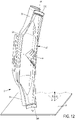
- the casing C is equipped with a cooling device D.
- the device D comprises one or more pressurized air supply boxes B, each of them being connected to several cooling ramps R which it supplies with air.
- the device D comprises two housings B, positioned at approximately 180° from each other, (only one being visible on the figure 1 ).
- the units B are connected to a pressurized air supply source by a tube T.
- Different supports S ensure the maintenance of the ramps R all around the housing C.
- front and the reference AV are used with reference to the front of the turbine and the term “rear” and the reference AR are used. with reference to the rear of the turbine (in relation to the direction of air circulation inside it).
- Each cooling ramp R is pierced with a plurality of perforations which emerge in line with the outer surface of the casing C. The same is true for the casing B.
- the pressurized air passing through these various perforations thus ensures a ventilation and cooling by impact on the crankcase C.
- the air collected in the casing B must supply the ramps R in a homogeneous and optimized manner, because otherwise there is a risk that areas of the casing C located opposite certain ramps are less well cooled than other areas of the casing located opposite other ramps.
- This casing comprises an angled air supply duct connected to a body delimiting an enclosure.
- This body has an outer wall and an opposite inner wall, this inner wall being provided with a plurality of air ejection perforations.
- the respective longitudinal edges of the two inner and outer walls of the body meet to define a first series of outlet pipes located on a first longitudinal side of the body and a second series of an identical number of outlet pipes located on 'a second longitudinal side of the body, each outlet pipe being configured to be connected to a cooling ramp of the cooling device.
- such a box is not in one piece and therefore cannot be manufactured by an additive manufacturing process.
- it does not include air distribution partitions improving the distribution of air in the various ramps.
- the object of the invention is therefore to solve the aforementioned drawbacks of the state of the art and to propose a pressurized air supply box which makes it possible to obtain a better distribution of the air in the enclosure of the box and therefore a better distribution of the air in each cooling ramp that it supplies.
- the invention relates to a box for supplying pressurized air to a device for cooling by air jets an external turbine casing of a turbomachine, this box comprising an elbow supply conduit for air and a body delimiting an enclosure, this body having an outer wall and an opposite inner wall extending in an axial direction D A , the inner wall of the body being provided with a plurality of air ejection perforations, the respective longitudinal edges of the two interior and exterior walls of the body meeting to define a first series of outlet pipes located on a first longitudinal side of the body and a second series of an identical number of outlet pipes located on a second longitudinal side of the body, each outlet duct being provided with an outlet opening configured to be connected to a cooling ramp of the cooling device, said air supply duct having an inner portion, an opposite outer portion and two side portions joining the inner portion to the outer portion.
- this housing is in one piece, said bent air supply duct is connected to the outer wall of the body so that its outlet mouth opens into said enclosure and its inner portion is located opposite -vis the part of the outer wall of the body which extends towards the first side of said body, and said housing comprises at least one air distribution partition, arranged in the outlet mouth of the supply duct air, this partition joining the inner face of the inner portion of the air supply duct to the inner face of the outer portion of the air supply duct.
- the air is better distributed in the housing and the distribution partition(s) contribute(s) to better distributing the air in the various cooling ramps fed from said housing.
- the turbine housing is better cooled and therefore engine performance is improved.
- this air supply box and its one-piece nature allows it to be manufactured using an additive manufacturing process.
- the invention also relates to a device for cooling by air jets an external turbine casing of a turbomachine.
- this device comprises a plurality of perforated, curved cooling ramps configured to be arranged around said outer casing and at least one pressurized air supply casing as mentioned above, the outlet openings of this casing being connected to the ends of said cooling ramps, so as to allow the pressurized air supply thereof.
- the invention also relates to a turbine, in particular a low-pressure turbine, of a turbomachine, such as a turbojet or an airplane turboprop, comprising an external casing. It comprises a device for cooling by air jets this casing as mentioned above.
- the invention relates to an additive manufacturing process by laser melting on a powder bed of a pressurized air supply unit as mentioned above.
- this method comprises a step of depositing on a horizontal support, a bed of a powder of the material constituting said box, then laser beam scanning of certain points of this powder bed to melt said powder and harden it and this step is repeated until said pressurized air supply box is obtained, these different successive powder layers being arranged in planes perpendicular to a vertical manufacturing direction, this vertical manufacturing direction being parallel or substantially parallel to a reference axis of the housing joining the center of an outlet opening of an outlet pipe on the second longitudinal side of the body in the center of an outlet opening of an outlet pipe of the first longitudinal side of the body, located opposite, the manufacture of the casing starting with the outlet pipes of the second longitudinal side of the body.
- the pressurized air supply box 2 is an element of a device 1 for cooling by air jets an external turbine casing of a turbomachine.
- the cooling device 1 also comprises a plurality of perforated cooling ramps 10, curved in the portion of an arc of a circle and arranged around the outer casing C of the turbine as described above in connection with the figures 1 and 2 .
- a plurality of perforated cooling ramps 10 curved in the portion of an arc of a circle and arranged around the outer casing C of the turbine as described above in connection with the figures 1 and 2 .
- ramps 10 On the figure 3 and 6 , only two portions of ramps 10 have been shown for simplification purposes.
- the arrows D A , D B and D C respectively indicate the axial direction, the radial direction and the circumferential direction of the turbine and of the casing.
- Box 2 is intended to replace box B shown on the figures 1 and 2 and to be positioned like the latter vis-à-vis the casing of the turbine.
- the guidelines for the departments have therefore been transferred to the figure 3 , 6 and 9 to show the orientation of the housing 2.
- the box 2 is in one piece, that is to say it is made in one piece, without welding or assembly of different parts. However, for to be able to describe it, it is considered that it comprises several subsets which will be described in more detail.
- the box 2 is manufactured by an additive manufacturing process by laser fusion on a powder bed and its shape has been designed accordingly.
- the box 2 comprises a body 3 delimiting an enclosure 300 and an angled air supply duct 4 (see figure 8 ).
- the body 3 has two opposite walls, namely an outer wall 31 and an inner wall 32, the latter being so named because it is intended to be positioned opposite the outer surface of the casing C to be cooled and because it is turned towards inside the turbine.
- the inner wall 32 is pierced with air ejection perforations 320.
- the body 3 has a generally elongated shape.
- One of the two longitudinal edges 311 of the outer wall 31 joins one of the two longitudinal edges 321 of the inner wall 32, so as to define a first series of outlet pipes 33, located on a first longitudinal side of the body 3 and the other of the two longitudinal edges 311 of the outer wall 31 joins the other of the two longitudinal edges 321 of the inner wall 32, so as to define a second series of an identical number of outlet pipes 34, located a second longitudinal side of the body 3.
- each series includes eight outlet lines 33 and eight outlet lines 34.
- Each outlet pipe 33 is substantially aligned with an outlet pipe 34 located opposite, with which it forms a pair of pipes.
- the geometries of the surfaces of the pipes 33 and 34 are smoothed, that is to say that their sections evolve progressively up to the outlet openings 330 , 340 respectively of each outlet pipe 33, 34.
- the pipes 33, 34 have a funnel shape which narrows as far as the outlet openings 330, 340, this shape being visible on the pipes 33 of the figure 4 .
- this geometry makes it possible to have an optimized thickness of the casing 2 and to reduce the overall mass of the casing while having good mechanical strength of the latter, including between two neighboring outlet pipes.
- the outlet openings 330 or 340 are preferably of circular cross-section and their inside diameter corresponds to the outside diameter of the cooling ramps 10. Thus the latter can be welded into the outlet openings.
- one of the two transverse edges 312 of the outer wall 31 joins one of the two transverse edges 322 of the inner wall 32, so as to define a so-called "front” end 35 of the body 3 and the other of the two transverse edges 312 of the outer wall 31 joins the other of the two transverse edges 322 of the inner wall 32, so as to define a so-called "rear” end 36 of the body 3.
- the denominations "front” and “ rear” are given with reference to the front and rear rear ends of the turbine when the casing 2 of the cooling device 1 is positioned around the casing of said turbine.
- the air supply duct 4 has an inlet mouth 41 and an outlet mouth 42. It is angled close to its outlet mouth 42, as is best seen on the figure 6 and 8 . Preferably, it flares out in width from its inlet mouth 41 to its outlet mouth 42, as seen in the picture 3 .
- the inlet mouth 41 is preferably of circular section. It is intended to be connected to a pressurized air supply source, not shown in the figures.
- the flared outlet mouth 42 is connected to the outer wall 31 of the body 3 at the level of an inlet mouth 38 (see figure 8 ) formed in this outer wall 31, so that the conduit 4 is in fluid communication with the interior of the body 3. In the embodiment of the picture 3 , this connection is made in the front part of the outer wall 31. However, the outlet mouth 42 could be more flared and the connection would then be made from the front part to the rear part of the outer wall 31.
- the outlet mouth 42 of the air supply duct 4 opens into the body 3 halfway between the outlet openings 330, 340.
- the wall which constitutes said duct 4 has four longitudinal portions, namely an inner portion 431, an opposite outer portion 432 and two lateral portions 433, 434 joining the inner portion to said outer portion. These portions are best visible on the figure 10A .
- the inner portion 431 extends opposite the outer wall 31 of the body 3 and more precisely, due to the bent shape of the duct 4, opposite the part of the outer wall 31 which extends towards the first side of the body 3 where the outlet pipes 33 of the first series of pipes are located (pipes facing upwards on the figure 6 ).
- At least one partition 37 for axial distribution (in the axial direction D A ) of the air is provided inside the outlet mouth 42 of the air supply duct 4.
- each partition 37 extends at least from the inner face of the inner portion 431 of the air supply duct 4 to the inner face of the outer portion 434 of the duct 4 (surface shown hatched on the figures 8 and 9 ).
- each partition extends more widely towards the inside of the duct 4 and/or towards the inside of the body 3.
- the partition 37' extends from the internal face of a part of the internal portion 431 of the air supply duct 4 and of the external wall 31 of the first side of the body 3 as far as the internal face of the outer portion 434 of conduit 4 (surface shown with crosses between the two dotted lines on the figures 8 and 9 ).
- each partition 37, 37' is curved from the outlet mouth 42 of the air supply duct 4 towards the inner wall 32 of the body 3 and the rear end 36 of the body 3.
- each partition 37, 37' is curved from the inner portion 431 in the direction of both the outer portion 432 and the rear end of the body 3 (to the left on the figure 10A ).
- This aerodynamic shape of the partitions 37, 37' promotes the guiding of the air flows (symbolized by the arrows i in figure 6 and 9 ), makes it possible to reduce pressure drops and to distribute the flows towards the various outlet openings 330, 340 in a controlled manner. It is easy to understand that the number, orientation and 3D geometry of each partition 37, 37' can be adapted to best distribute the air flow according to the number of ramps to be supplied and the desired size of the box 2.
- the housing 2 is advantageously manufactured by additive manufacturing by laser melting on a powder bed. It is preferably made of metal, for example Inconel 718.
- Additive manufacturing is carried out by depositing successive layers on a horizontal support P represented partially on the figure 6 and 12 and schematically on the figure 8 .
- a layer of a powder of the material constituting the casing 2 is placed on the support P, then the powder is melted at certain points by scanning with the aid of a laser beam. This step is repeated until box 2 is obtained.
- the direction of construction is vertical and the direction of construction of the box 2 is represented by the vertical arrow F from bottom to top.
- the vertical direction of construction is parallel or substantially parallel to a reference axis XX' shown in figure 12 and which joins the center of an outlet opening 340 of a pipe 34 on the second longitudinal side of the body 3 to the center of an outlet opening 330 of a pipe 33 on the first longitudinal side of the body 3, located opposite (in other words, which joins the centers of the two openings of a pair of pipes).
- the inner 32 and outer 31 walls of the body 3 and the various portions 431 to 434 of the duct 4 form with respect to the vertical direction of construction, an angle ⁇ equal to a maximum of 50°, which makes it possible to avoid any support during manufacture or machining of parts superfluous after manufacture.
- all the walls must not exceed this angle of 50° so as not to be too horizontal and risk not being supported by the layer of unfused powder located below.
- the different walls of the housing 2 form a maximum angle ⁇ of 50° with the aforementioned reference axis XX'.
- partitions 37, 37' make it possible to support the interior portion 431 of the duct 4 which is located above (shown in gray on the figure 9 and visible on the figure 10A ).
- the inner portion 431 has several V-shaped connection zones, namely a V-shaped connection zone 4311 between the lateral portion 433, respectively 434, of the duct 4 and the air distribution partition 37, 37' located next to it. If there are at least two partitions 37, 37', the portion 431 also has a V-shaped connection zone 4312 between two adjacent partitions 37, 37'.
- V-connection areas are also visible on the figure 13 . They extend along the axial direction D A .
- the tip of the V protrudes towards the space provided between the duct 4 and the body 3 (towards the top of the figure 6 ).
- This space also has a V or U shape and extends in the radial direction D B .
- the inverted V forms a kind of vault which can also be manufactured by additive manufacturing without additional support.
- the outlet mouth 42 of the air supply duct 4 is connected to the outer wall 31 of the body 3 in an inclined manner, so that it tends to guide the air more towards the outlet ducts 34 of the second side (towards the bottom of the figure).
- the housing 2 comprises a spout 5 for circumferential distribution of the air flow, arranged inside the body 3 and which tends to force the flow of part of the flow of air to the first side (up on the figure 8 ), to better balance the distribution of flows on either side of box 2.
- This beak 5 has the shape of a blade folded in two, with a V-shaped cross-section, placed at the center or substantially at the center of the inner wall 32 of the body 3, so that the tip of the V protrudes towards the inside of the body.
- This spout 5 preferably extends from the front end to the rear end of the body 3 (see also the figure 12 ).
- This spout 5 is provided with a plurality of notches 50 which allow the circulation of air from the interior of a body 3 in the direction of the air ejection perforations 320 and which make it possible to depowder the part c' that is to say, to effectively eliminate, at the end of manufacture, the layers of powder located between the spout 5 and the wall 32 and which have not been fused by the laser beam.
- this spout 5 and its angles of inclination with respect to the vertical direction of construction F are compatible with an additive manufacturing process (less than 50°).
- the inner wall 32 of the body 3 has air ejection perforations 320 which place the inside of said body in communication with the casing C to be cooled.
- perforations 320 are aligned in the form of at least one line of perforations which extends for each pair of exit openings, from an exit opening 330 located on the first side of the body 3 to the exit opening 340 located on the second side of the body 3.
- the inner wall 32 of the body 3 has strips 323 forming an extra thickness of material, each strip 323 extending from an outlet opening 330 to an exit aperture 340 of the same pair of exit apertures.
- this thickened band 323 (that is to say the surface facing the casing C) is curved from the opening 330 to the opening 340 according to an arcuate shape whose radius R1 is greater than the radius R2 of the circular section of the housing C to be cooled located opposite.
- the perforations 320 are made through this extra thick strip of material 323.
- a constant air gap E is thus obtained between the outlet of the perforations 320 and the casing C.
- the perforations 320 thus extend over a greater part of the housing 2 and the uncooled zones Z of the housing C are reduced.
- the front end 35 and/or the rear end 36 of the casing 3 is provided with a fixing element 6 of the casing 2 on the casing C to be cooled.
- This fixing element 6 is for example a flange 61 or a fixing lug 62. It is one piece with the body 3.
- the fixing flange 61 and the fixing lug 62 have a flat portion 610, respectively 620, allowing fixing on a flat surface. Furthermore, the junction parts 611, respectively 621, between the planar portion 610, respectively 620, and the body 3 are formed with angles compatible with additive manufacturing without additional construction support.
Landscapes
- Engineering & Computer Science (AREA)
- Mechanical Engineering (AREA)
- General Engineering & Computer Science (AREA)
- Chemical & Material Sciences (AREA)
- Combustion & Propulsion (AREA)
- Turbine Rotor Nozzle Sealing (AREA)
Applications Claiming Priority (2)
| Application Number | Priority Date | Filing Date | Title |
|---|---|---|---|
| FR1858021A FR3085719B1 (fr) | 2018-09-06 | 2018-09-06 | Boitier d'alimentation en air sous pression d'un dispositif de refroidissement par jets d'air |
| PCT/FR2019/052047 WO2020049259A1 (fr) | 2018-09-06 | 2019-09-06 | Boîtier d'alimentation en air sous pression d'un dispositif de refroidissement par jets d'air |
Publications (2)
| Publication Number | Publication Date |
|---|---|
| EP3847342A1 EP3847342A1 (fr) | 2021-07-14 |
| EP3847342B1 true EP3847342B1 (fr) | 2022-08-10 |
Family
ID=63722666
Family Applications (1)
| Application Number | Title | Priority Date | Filing Date |
|---|---|---|---|
| EP19783592.9A Active EP3847342B1 (fr) | 2018-09-06 | 2019-09-06 | Boîtier d'alimentation en air sous pression d'un dispositif de refroidissement par jets d'air |
Country Status (6)
| Country | Link |
|---|---|
| US (1) | US11280217B2 (zh) |
| EP (1) | EP3847342B1 (zh) |
| CN (1) | CN112673150B (zh) |
| CA (1) | CA3110912A1 (zh) |
| FR (1) | FR3085719B1 (zh) |
| WO (1) | WO2020049259A1 (zh) |
Family Cites Families (32)
| Publication number | Priority date | Publication date | Assignee | Title |
|---|---|---|---|---|
| US4053254A (en) * | 1976-03-26 | 1977-10-11 | United Technologies Corporation | Turbine case cooling system |
| US5205115A (en) * | 1991-11-04 | 1993-04-27 | General Electric Company | Gas turbine engine case counterflow thermal control |
| FR2766232B1 (fr) * | 1997-07-18 | 1999-08-20 | Snecma | Dispositif de refroidissement ou d'echauffement d'un carter circulaire |
| FR2766231B1 (fr) * | 1997-07-18 | 1999-08-20 | Snecma | Dispositif d'echauffement ou de refroidissement d'un carter circulaire |
| US6851514B2 (en) * | 2002-04-15 | 2005-02-08 | Air Handling Engineering Ltd. | Outlet silencer and heat recovery structures for gas turbine |
| US7597537B2 (en) * | 2005-12-16 | 2009-10-06 | General Electric Company | Thermal control of gas turbine engine rings for active clearance control |
| US7503179B2 (en) * | 2005-12-16 | 2009-03-17 | General Electric Company | System and method to exhaust spent cooling air of gas turbine engine active clearance control |
| US7600370B2 (en) * | 2006-05-25 | 2009-10-13 | Siemens Energy, Inc. | Fluid flow distributor apparatus for gas turbine engine mid-frame section |
| US8801370B2 (en) * | 2006-10-12 | 2014-08-12 | General Electric Company | Turbine case impingement cooling for heavy duty gas turbines |
| GB0904118D0 (en) * | 2009-03-11 | 2009-04-22 | Rolls Royce Plc | An impingement cooling arrangement for a gas turbine engine |
| GB201013723D0 (en) * | 2010-08-17 | 2010-09-29 | Rolls Royce Plc | Manifold mounting arrangement |
| FR2977276B1 (fr) * | 2011-06-30 | 2016-12-09 | Snecma | Agencement pour le raccordement d'un conduit a un boitier de distribution d'air |
| US9341074B2 (en) * | 2012-07-25 | 2016-05-17 | General Electric Company | Active clearance control manifold system |
| US8920109B2 (en) * | 2013-03-12 | 2014-12-30 | Siemens Aktiengesellschaft | Vane carrier thermal management arrangement and method for clearance control |
| DE102013006955A1 (de) * | 2013-04-23 | 2014-10-23 | Modine Manufacturing Co. | Saugrohr mit einem Ladeluftkühler |
| US9869196B2 (en) * | 2014-06-24 | 2018-01-16 | General Electric Company | Gas turbine engine spring mounted manifold |
| EP2960436B1 (en) * | 2014-06-27 | 2017-08-09 | Ansaldo Energia Switzerland AG | Cooling structure for a transition piece of a gas turbine |
| FR3040429B1 (fr) * | 2015-08-27 | 2019-06-07 | Safran Aircraft Engines | Dispositif de fixation des rampes de refroidissement par jets d'air du carter d'une turbine de turbomachine |
| FR3040428B1 (fr) * | 2015-08-27 | 2017-09-01 | Snecma | Dispositif de refroidissement par jets d'air du carter d'une turbine d'une turbomachine |
| US10125632B2 (en) * | 2015-10-20 | 2018-11-13 | General Electric Company | Wheel space purge flow mixing chamber |
| US20170114667A1 (en) * | 2015-10-23 | 2017-04-27 | General Electric Company | Active clearance control with integral double wall heat shielding |
| FR3044705B1 (fr) * | 2015-12-07 | 2019-11-01 | Safran Aircraft Engines | Systeme de decharge d'un flux de compresseur d'une turbomachine |
| FR3050228B1 (fr) * | 2016-04-18 | 2019-03-29 | Safran Aircraft Engines | Dispositif de refroidissement par jets d'air d'un carter de turbine |
| US10329941B2 (en) * | 2016-05-06 | 2019-06-25 | United Technologies Corporation | Impingement manifold |
| FR3058460B1 (fr) * | 2016-11-08 | 2018-11-09 | Safran Aircraft Engines | Ensemble de raccordement pour le refroidissement d'une turbine de turbomachine |
| US10544803B2 (en) * | 2017-04-17 | 2020-01-28 | General Electric Company | Method and system for cooling fluid distribution |
| FR3073007B1 (fr) * | 2017-10-27 | 2019-09-27 | Safran Aircraft Engines | Dispositif de maintien d'un tube de refroidissement pour carter de turbomachine |
| US20190136708A1 (en) * | 2017-11-09 | 2019-05-09 | General Electric Company | Active clearance control cooling air rail with fingers |
| US20190170009A1 (en) * | 2017-12-05 | 2019-06-06 | General Electric Company | Turbine engine with clearance control system |
| FR3079560B1 (fr) * | 2018-04-03 | 2020-10-09 | Safran Aircraft Engines | Dispositif de refroidissement pour une turbine d'une turbomachine |
| FR3082872B1 (fr) * | 2018-06-25 | 2021-06-04 | Safran Aircraft Engines | Dispositif de refroidissement d'un carter de turbomachine |
| EP3800330B1 (en) * | 2019-10-01 | 2021-12-08 | ITP Externals, S.L. | Panel for tip clearance control |
-
2018
- 2018-09-06 FR FR1858021A patent/FR3085719B1/fr active Active
-
2019
- 2019-09-06 CA CA3110912A patent/CA3110912A1/fr active Pending
- 2019-09-06 US US17/273,665 patent/US11280217B2/en active Active
- 2019-09-06 CN CN201980058127.XA patent/CN112673150B/zh active Active
- 2019-09-06 EP EP19783592.9A patent/EP3847342B1/fr active Active
- 2019-09-06 WO PCT/FR2019/052047 patent/WO2020049259A1/fr unknown
Also Published As
| Publication number | Publication date |
|---|---|
| FR3085719A1 (fr) | 2020-03-13 |
| WO2020049259A1 (fr) | 2020-03-12 |
| CN112673150B (zh) | 2022-10-14 |
| US20210396152A1 (en) | 2021-12-23 |
| CN112673150A (zh) | 2021-04-16 |
| CA3110912A1 (fr) | 2020-03-12 |
| EP3847342A1 (fr) | 2021-07-14 |
| FR3085719B1 (fr) | 2021-04-16 |
| US11280217B2 (en) | 2022-03-22 |
Similar Documents
| Publication | Publication Date | Title |
|---|---|---|
| EP3445949B1 (fr) | Dispositif de refroidissement par jets d'air d'un carter de turbine | |
| FR3029959A1 (fr) | Refroidissement de composants de moteur | |
| EP3463737B1 (fr) | Carter d'echappement de turbomachine et son procede de fabrication | |
| EP1930659B1 (fr) | Chambre de combustion de turboréacteur | |
| EP3683429B1 (fr) | Structure interne d'un conduit d'ejection primaire | |
| WO2020217025A1 (fr) | Entrée d'air de nacelle et nacelle comportant une telle entrée d'air | |
| EP1489359A1 (fr) | Chambre de combustion annulaire de turbomachine | |
| WO2004113794A1 (fr) | Chambre de combustion annulaire de turbomachine | |
| EP3847342B1 (fr) | Boîtier d'alimentation en air sous pression d'un dispositif de refroidissement par jets d'air | |
| FR3098247A1 (fr) | Trompe a jet pour turbomachine | |
| EP3797248A1 (fr) | Fond de chambre de combustion de turbomachine | |
| WO1986003824A1 (fr) | Paroi de foyer comportant des buses d'alimentation moulees en deux parties complementaires | |
| EP3183498B1 (fr) | Dispositif de raccordement comportant plusieurs tubes concentriques cintrés | |
| FR3017928B1 (fr) | Turbomachine a bride externe de chambre de combustion de type "sandwich" | |
| EP3638412B1 (fr) | Element d'injection de gaz pour unite de craquage catalytique fluide et systeme de distribution de gaz equipe de cet element d'injection | |
| EP3724076A1 (fr) | Lèvre d'entrée d'air de nacelle pour turboréacteur | |
| WO1999040376A1 (fr) | Corps de chauffe pour une chaudiere au fioul ou au gaz et modules pour la realisation d'un tel corps de chauffe | |
| EP3645944B1 (fr) | Injecteur de carburant a jet plat pour une turbomachine d'aeronef | |
| FR3135313A1 (fr) | Brûleur à gaz à combustion de surface antidéflagrant et antidétonant. | |
| FR3119340A1 (fr) | Procede de fabrication d'un secteur de distributeur ou de redresseur. | |
| EP3980692A1 (fr) | Procédé de fabrication d'un tube à flamme pour une turbomachine | |
| FR3083303A1 (fr) | Radiateur a elements radiants integrant un separateur d'ecoulement | |
| FR3121180A1 (fr) | Tube d’ejection integre a un tube central de ventilation | |
| FR3079499A1 (fr) | Partie anterieure de nacelle comportant un cadre de rigidification constitue de plusieurs elements adjacents assembles sur un premier anneau et un deuxieme anneau | |
| WO2014053760A1 (fr) | Fond de chambre annulaire pour chambre de combustion de turbomachine d'aeronef, muni de perforations permettant un refroidissement par flux giratoire |
Legal Events
| Date | Code | Title | Description |
|---|---|---|---|
| STAA | Information on the status of an ep patent application or granted ep patent |
Free format text: STATUS: UNKNOWN |
|
| STAA | Information on the status of an ep patent application or granted ep patent |
Free format text: STATUS: THE INTERNATIONAL PUBLICATION HAS BEEN MADE |
|
| PUAI | Public reference made under article 153(3) epc to a published international application that has entered the european phase |
Free format text: ORIGINAL CODE: 0009012 |
|
| STAA | Information on the status of an ep patent application or granted ep patent |
Free format text: STATUS: REQUEST FOR EXAMINATION WAS MADE |
|
| 17P | Request for examination filed |
Effective date: 20210325 |
|
| AK | Designated contracting states |
Kind code of ref document: A1 Designated state(s): AL AT BE BG CH CY CZ DE DK EE ES FI FR GB GR HR HU IE IS IT LI LT LU LV MC MK MT NL NO PL PT RO RS SE SI SK SM TR |
|
| DAV | Request for validation of the european patent (deleted) | ||
| DAX | Request for extension of the european patent (deleted) | ||
| GRAP | Despatch of communication of intention to grant a patent |
Free format text: ORIGINAL CODE: EPIDOSNIGR1 |
|
| STAA | Information on the status of an ep patent application or granted ep patent |
Free format text: STATUS: GRANT OF PATENT IS INTENDED |
|
| INTG | Intention to grant announced |
Effective date: 20220331 |
|
| GRAS | Grant fee paid |
Free format text: ORIGINAL CODE: EPIDOSNIGR3 |
|
| GRAA | (expected) grant |
Free format text: ORIGINAL CODE: 0009210 |
|
| STAA | Information on the status of an ep patent application or granted ep patent |
Free format text: STATUS: THE PATENT HAS BEEN GRANTED |
|
| AK | Designated contracting states |
Kind code of ref document: B1 Designated state(s): AL AT BE BG CH CY CZ DE DK EE ES FI FR GB GR HR HU IE IS IT LI LT LU LV MC MK MT NL NO PL PT RO RS SE SI SK SM TR |
|
| REG | Reference to a national code |
Ref country code: AT Ref legal event code: REF Ref document number: 1510688 Country of ref document: AT Kind code of ref document: T Effective date: 20220815 Ref country code: CH Ref legal event code: EP |
|
| REG | Reference to a national code |
Ref country code: IE Ref legal event code: FG4D Free format text: LANGUAGE OF EP DOCUMENT: FRENCH |
|
| REG | Reference to a national code |
Ref country code: DE Ref legal event code: R096 Ref document number: 602019018194 Country of ref document: DE |
|
| REG | Reference to a national code |
Ref country code: NL Ref legal event code: MP Effective date: 20220810 |
|
| REG | Reference to a national code |
Ref country code: LT Ref legal event code: MG9D |
|
| PG25 | Lapsed in a contracting state [announced via postgrant information from national office to epo] |
Ref country code: SE Free format text: LAPSE BECAUSE OF FAILURE TO SUBMIT A TRANSLATION OF THE DESCRIPTION OR TO PAY THE FEE WITHIN THE PRESCRIBED TIME-LIMIT Effective date: 20220810 Ref country code: RS Free format text: LAPSE BECAUSE OF FAILURE TO SUBMIT A TRANSLATION OF THE DESCRIPTION OR TO PAY THE FEE WITHIN THE PRESCRIBED TIME-LIMIT Effective date: 20220810 Ref country code: PT Free format text: LAPSE BECAUSE OF FAILURE TO SUBMIT A TRANSLATION OF THE DESCRIPTION OR TO PAY THE FEE WITHIN THE PRESCRIBED TIME-LIMIT Effective date: 20221212 Ref country code: NO Free format text: LAPSE BECAUSE OF FAILURE TO SUBMIT A TRANSLATION OF THE DESCRIPTION OR TO PAY THE FEE WITHIN THE PRESCRIBED TIME-LIMIT Effective date: 20221110 Ref country code: NL Free format text: LAPSE BECAUSE OF FAILURE TO SUBMIT A TRANSLATION OF THE DESCRIPTION OR TO PAY THE FEE WITHIN THE PRESCRIBED TIME-LIMIT Effective date: 20220810 Ref country code: LV Free format text: LAPSE BECAUSE OF FAILURE TO SUBMIT A TRANSLATION OF THE DESCRIPTION OR TO PAY THE FEE WITHIN THE PRESCRIBED TIME-LIMIT Effective date: 20220810 Ref country code: LT Free format text: LAPSE BECAUSE OF FAILURE TO SUBMIT A TRANSLATION OF THE DESCRIPTION OR TO PAY THE FEE WITHIN THE PRESCRIBED TIME-LIMIT Effective date: 20220810 Ref country code: FI Free format text: LAPSE BECAUSE OF FAILURE TO SUBMIT A TRANSLATION OF THE DESCRIPTION OR TO PAY THE FEE WITHIN THE PRESCRIBED TIME-LIMIT Effective date: 20220810 |
|
| REG | Reference to a national code |
Ref country code: AT Ref legal event code: MK05 Ref document number: 1510688 Country of ref document: AT Kind code of ref document: T Effective date: 20220810 |
|
| PG25 | Lapsed in a contracting state [announced via postgrant information from national office to epo] |
Ref country code: PL Free format text: LAPSE BECAUSE OF FAILURE TO SUBMIT A TRANSLATION OF THE DESCRIPTION OR TO PAY THE FEE WITHIN THE PRESCRIBED TIME-LIMIT Effective date: 20220810 Ref country code: IS Free format text: LAPSE BECAUSE OF FAILURE TO SUBMIT A TRANSLATION OF THE DESCRIPTION OR TO PAY THE FEE WITHIN THE PRESCRIBED TIME-LIMIT Effective date: 20221210 Ref country code: HR Free format text: LAPSE BECAUSE OF FAILURE TO SUBMIT A TRANSLATION OF THE DESCRIPTION OR TO PAY THE FEE WITHIN THE PRESCRIBED TIME-LIMIT Effective date: 20220810 Ref country code: GR Free format text: LAPSE BECAUSE OF FAILURE TO SUBMIT A TRANSLATION OF THE DESCRIPTION OR TO PAY THE FEE WITHIN THE PRESCRIBED TIME-LIMIT Effective date: 20221111 |
|
| PG25 | Lapsed in a contracting state [announced via postgrant information from national office to epo] |
Ref country code: SM Free format text: LAPSE BECAUSE OF FAILURE TO SUBMIT A TRANSLATION OF THE DESCRIPTION OR TO PAY THE FEE WITHIN THE PRESCRIBED TIME-LIMIT Effective date: 20220810 Ref country code: RO Free format text: LAPSE BECAUSE OF FAILURE TO SUBMIT A TRANSLATION OF THE DESCRIPTION OR TO PAY THE FEE WITHIN THE PRESCRIBED TIME-LIMIT Effective date: 20220810 Ref country code: ES Free format text: LAPSE BECAUSE OF FAILURE TO SUBMIT A TRANSLATION OF THE DESCRIPTION OR TO PAY THE FEE WITHIN THE PRESCRIBED TIME-LIMIT Effective date: 20220810 Ref country code: DK Free format text: LAPSE BECAUSE OF FAILURE TO SUBMIT A TRANSLATION OF THE DESCRIPTION OR TO PAY THE FEE WITHIN THE PRESCRIBED TIME-LIMIT Effective date: 20220810 Ref country code: CZ Free format text: LAPSE BECAUSE OF FAILURE TO SUBMIT A TRANSLATION OF THE DESCRIPTION OR TO PAY THE FEE WITHIN THE PRESCRIBED TIME-LIMIT Effective date: 20220810 Ref country code: AT Free format text: LAPSE BECAUSE OF FAILURE TO SUBMIT A TRANSLATION OF THE DESCRIPTION OR TO PAY THE FEE WITHIN THE PRESCRIBED TIME-LIMIT Effective date: 20220810 |
|
| REG | Reference to a national code |
Ref country code: CH Ref legal event code: PL |
|
| REG | Reference to a national code |
Ref country code: DE Ref legal event code: R097 Ref document number: 602019018194 Country of ref document: DE |
|
| REG | Reference to a national code |
Ref country code: BE Ref legal event code: MM Effective date: 20220930 |
|
| PG25 | Lapsed in a contracting state [announced via postgrant information from national office to epo] |
Ref country code: SK Free format text: LAPSE BECAUSE OF FAILURE TO SUBMIT A TRANSLATION OF THE DESCRIPTION OR TO PAY THE FEE WITHIN THE PRESCRIBED TIME-LIMIT Effective date: 20220810 Ref country code: MC Free format text: LAPSE BECAUSE OF FAILURE TO SUBMIT A TRANSLATION OF THE DESCRIPTION OR TO PAY THE FEE WITHIN THE PRESCRIBED TIME-LIMIT Effective date: 20220810 Ref country code: EE Free format text: LAPSE BECAUSE OF FAILURE TO SUBMIT A TRANSLATION OF THE DESCRIPTION OR TO PAY THE FEE WITHIN THE PRESCRIBED TIME-LIMIT Effective date: 20220810 |
|
| PLBE | No opposition filed within time limit |
Free format text: ORIGINAL CODE: 0009261 |
|
| STAA | Information on the status of an ep patent application or granted ep patent |
Free format text: STATUS: NO OPPOSITION FILED WITHIN TIME LIMIT |
|
| PG25 | Lapsed in a contracting state [announced via postgrant information from national office to epo] |
Ref country code: LU Free format text: LAPSE BECAUSE OF NON-PAYMENT OF DUE FEES Effective date: 20220906 Ref country code: AL Free format text: LAPSE BECAUSE OF FAILURE TO SUBMIT A TRANSLATION OF THE DESCRIPTION OR TO PAY THE FEE WITHIN THE PRESCRIBED TIME-LIMIT Effective date: 20220810 |
|
| 26N | No opposition filed |
Effective date: 20230511 |
|
| PG25 | Lapsed in a contracting state [announced via postgrant information from national office to epo] |
Ref country code: LI Free format text: LAPSE BECAUSE OF NON-PAYMENT OF DUE FEES Effective date: 20220930 Ref country code: IE Free format text: LAPSE BECAUSE OF NON-PAYMENT OF DUE FEES Effective date: 20220906 Ref country code: CH Free format text: LAPSE BECAUSE OF NON-PAYMENT OF DUE FEES Effective date: 20220930 |
|
| PG25 | Lapsed in a contracting state [announced via postgrant information from national office to epo] |
Ref country code: SI Free format text: LAPSE BECAUSE OF FAILURE TO SUBMIT A TRANSLATION OF THE DESCRIPTION OR TO PAY THE FEE WITHIN THE PRESCRIBED TIME-LIMIT Effective date: 20220810 |
|
| PG25 | Lapsed in a contracting state [announced via postgrant information from national office to epo] |
Ref country code: BE Free format text: LAPSE BECAUSE OF NON-PAYMENT OF DUE FEES Effective date: 20220930 |
|
| PGFP | Annual fee paid to national office [announced via postgrant information from national office to epo] |
Ref country code: GB Payment date: 20230823 Year of fee payment: 5 |
|
| PGFP | Annual fee paid to national office [announced via postgrant information from national office to epo] |
Ref country code: FR Payment date: 20230822 Year of fee payment: 5 Ref country code: DE Payment date: 20230822 Year of fee payment: 5 |
|
| PG25 | Lapsed in a contracting state [announced via postgrant information from national office to epo] |
Ref country code: CY Free format text: LAPSE BECAUSE OF FAILURE TO SUBMIT A TRANSLATION OF THE DESCRIPTION OR TO PAY THE FEE WITHIN THE PRESCRIBED TIME-LIMIT Effective date: 20220810 |