EP3845964B1 - Illumination device and display device - Google Patents
Illumination device and display device Download PDFInfo
- Publication number
- EP3845964B1 EP3845964B1 EP19853360.6A EP19853360A EP3845964B1 EP 3845964 B1 EP3845964 B1 EP 3845964B1 EP 19853360 A EP19853360 A EP 19853360A EP 3845964 B1 EP3845964 B1 EP 3845964B1
- Authority
- EP
- European Patent Office
- Prior art keywords
- light
- illumination light
- image
- light source
- illumination
- Prior art date
- Legal status (The legal status is an assumption and is not a legal conclusion. Google has not performed a legal analysis and makes no representation as to the accuracy of the status listed.)
- Active
Links
Images


Classifications
-
- H—ELECTRICITY
- H04—ELECTRIC COMMUNICATION TECHNIQUE
- H04N—PICTORIAL COMMUNICATION, e.g. TELEVISION
- H04N9/00—Details of colour television systems
- H04N9/12—Picture reproducers
- H04N9/31—Projection devices for colour picture display, e.g. using electronic spatial light modulators [ESLM]
- H04N9/3141—Constructional details thereof
- H04N9/315—Modulator illumination systems
- H04N9/3155—Modulator illumination systems for controlling the light source
-
- H—ELECTRICITY
- H04—ELECTRIC COMMUNICATION TECHNIQUE
- H04N—PICTORIAL COMMUNICATION, e.g. TELEVISION
- H04N9/00—Details of colour television systems
- H04N9/12—Picture reproducers
- H04N9/31—Projection devices for colour picture display, e.g. using electronic spatial light modulators [ESLM]
- H04N9/3102—Projection devices for colour picture display, e.g. using electronic spatial light modulators [ESLM] using two-dimensional electronic spatial light modulators
- H04N9/312—Driving therefor
- H04N9/3126—Driving therefor for spatial light modulators in series
-
- G—PHYSICS
- G02—OPTICS
- G02B—OPTICAL ELEMENTS, SYSTEMS OR APPARATUS
- G02B26/00—Optical devices or arrangements for the control of light using movable or deformable optical elements
- G02B26/08—Optical devices or arrangements for the control of light using movable or deformable optical elements for controlling the direction of light
-
- G—PHYSICS
- G02—OPTICS
- G02B—OPTICAL ELEMENTS, SYSTEMS OR APPARATUS
- G02B27/00—Optical systems or apparatus not provided for by any of the groups G02B1/00 - G02B26/00, G02B30/00
- G02B27/28—Optical systems or apparatus not provided for by any of the groups G02B1/00 - G02B26/00, G02B30/00 for polarising
-
- G—PHYSICS
- G02—OPTICS
- G02B—OPTICAL ELEMENTS, SYSTEMS OR APPARATUS
- G02B5/00—Optical elements other than lenses
- G02B5/18—Diffraction gratings
-
- G—PHYSICS
- G02—OPTICS
- G02B—OPTICAL ELEMENTS, SYSTEMS OR APPARATUS
- G02B5/00—Optical elements other than lenses
- G02B5/30—Polarising elements
-
- G—PHYSICS
- G02—OPTICS
- G02F—OPTICAL DEVICES OR ARRANGEMENTS FOR THE CONTROL OF LIGHT BY MODIFICATION OF THE OPTICAL PROPERTIES OF THE MEDIA OF THE ELEMENTS INVOLVED THEREIN; NON-LINEAR OPTICS; FREQUENCY-CHANGING OF LIGHT; OPTICAL LOGIC ELEMENTS; OPTICAL ANALOGUE/DIGITAL CONVERTERS
- G02F1/00—Devices or arrangements for the control of the intensity, colour, phase, polarisation or direction of light arriving from an independent light source, e.g. switching, gating or modulating; Non-linear optics
- G02F1/01—Devices or arrangements for the control of the intensity, colour, phase, polarisation or direction of light arriving from an independent light source, e.g. switching, gating or modulating; Non-linear optics for the control of the intensity, phase, polarisation or colour
- G02F1/13—Devices or arrangements for the control of the intensity, colour, phase, polarisation or direction of light arriving from an independent light source, e.g. switching, gating or modulating; Non-linear optics for the control of the intensity, phase, polarisation or colour based on liquid crystals, e.g. single liquid crystal display cells
- G02F1/137—Devices or arrangements for the control of the intensity, colour, phase, polarisation or direction of light arriving from an independent light source, e.g. switching, gating or modulating; Non-linear optics for the control of the intensity, phase, polarisation or colour based on liquid crystals, e.g. single liquid crystal display cells characterised by the electro-optical or magneto-optical effect, e.g. field-induced phase transition, orientation effect, guest-host interaction or dynamic scattering
- G02F1/13731—Devices or arrangements for the control of the intensity, colour, phase, polarisation or direction of light arriving from an independent light source, e.g. switching, gating or modulating; Non-linear optics for the control of the intensity, phase, polarisation or colour based on liquid crystals, e.g. single liquid crystal display cells characterised by the electro-optical or magneto-optical effect, e.g. field-induced phase transition, orientation effect, guest-host interaction or dynamic scattering based on a field-induced phase transition
-
- G—PHYSICS
- G03—PHOTOGRAPHY; CINEMATOGRAPHY; ANALOGOUS TECHNIQUES USING WAVES OTHER THAN OPTICAL WAVES; ELECTROGRAPHY; HOLOGRAPHY
- G03B—APPARATUS OR ARRANGEMENTS FOR TAKING PHOTOGRAPHS OR FOR PROJECTING OR VIEWING THEM; APPARATUS OR ARRANGEMENTS EMPLOYING ANALOGOUS TECHNIQUES USING WAVES OTHER THAN OPTICAL WAVES; ACCESSORIES THEREFOR
- G03B21/00—Projectors or projection-type viewers; Accessories therefor
- G03B21/005—Projectors using an electronic spatial light modulator but not peculiar thereto
-
- G—PHYSICS
- G03—PHOTOGRAPHY; CINEMATOGRAPHY; ANALOGOUS TECHNIQUES USING WAVES OTHER THAN OPTICAL WAVES; ELECTROGRAPHY; HOLOGRAPHY
- G03B—APPARATUS OR ARRANGEMENTS FOR TAKING PHOTOGRAPHS OR FOR PROJECTING OR VIEWING THEM; APPARATUS OR ARRANGEMENTS EMPLOYING ANALOGOUS TECHNIQUES USING WAVES OTHER THAN OPTICAL WAVES; ACCESSORIES THEREFOR
- G03B21/00—Projectors or projection-type viewers; Accessories therefor
- G03B21/14—Details
- G03B21/20—Lamp housings
- G03B21/2073—Polarisers in the lamp house
-
- G—PHYSICS
- G09—EDUCATION; CRYPTOGRAPHY; DISPLAY; ADVERTISING; SEALS
- G09G—ARRANGEMENTS OR CIRCUITS FOR CONTROL OF INDICATING DEVICES USING STATIC MEANS TO PRESENT VARIABLE INFORMATION
- G09G3/00—Control arrangements or circuits, of interest only in connection with visual indicators other than cathode-ray tubes
- G09G3/20—Control arrangements or circuits, of interest only in connection with visual indicators other than cathode-ray tubes for presentation of an assembly of a number of characters, e.g. a page, by composing the assembly by combination of individual elements arranged in a matrix no fixed position being assigned to or needed to be assigned to the individual characters or partial characters
- G09G3/34—Control arrangements or circuits, of interest only in connection with visual indicators other than cathode-ray tubes for presentation of an assembly of a number of characters, e.g. a page, by composing the assembly by combination of individual elements arranged in a matrix no fixed position being assigned to or needed to be assigned to the individual characters or partial characters by control of light from an independent source
- G09G3/36—Control arrangements or circuits, of interest only in connection with visual indicators other than cathode-ray tubes for presentation of an assembly of a number of characters, e.g. a page, by composing the assembly by combination of individual elements arranged in a matrix no fixed position being assigned to or needed to be assigned to the individual characters or partial characters by control of light from an independent source using liquid crystals
-
- H—ELECTRICITY
- H04—ELECTRIC COMMUNICATION TECHNIQUE
- H04N—PICTORIAL COMMUNICATION, e.g. TELEVISION
- H04N9/00—Details of colour television systems
- H04N9/12—Picture reproducers
- H04N9/31—Projection devices for colour picture display, e.g. using electronic spatial light modulators [ESLM]
- H04N9/3141—Constructional details thereof
- H04N9/315—Modulator illumination systems
- H04N9/3161—Modulator illumination systems using laser light sources
-
- H—ELECTRICITY
- H04—ELECTRIC COMMUNICATION TECHNIQUE
- H04N—PICTORIAL COMMUNICATION, e.g. TELEVISION
- H04N9/00—Details of colour television systems
- H04N9/12—Picture reproducers
- H04N9/31—Projection devices for colour picture display, e.g. using electronic spatial light modulators [ESLM]
- H04N9/3141—Constructional details thereof
- H04N9/315—Modulator illumination systems
- H04N9/3164—Modulator illumination systems using multiple light sources
-
- H—ELECTRICITY
- H04—ELECTRIC COMMUNICATION TECHNIQUE
- H04N—PICTORIAL COMMUNICATION, e.g. TELEVISION
- H04N9/00—Details of colour television systems
- H04N9/12—Picture reproducers
- H04N9/31—Projection devices for colour picture display, e.g. using electronic spatial light modulators [ESLM]
- H04N9/3141—Constructional details thereof
- H04N9/315—Modulator illumination systems
- H04N9/3167—Modulator illumination systems for polarizing the light beam
-
- H—ELECTRICITY
- H04—ELECTRIC COMMUNICATION TECHNIQUE
- H04N—PICTORIAL COMMUNICATION, e.g. TELEVISION
- H04N9/00—Details of colour television systems
- H04N9/12—Picture reproducers
- H04N9/31—Projection devices for colour picture display, e.g. using electronic spatial light modulators [ESLM]
- H04N9/3179—Video signal processing therefor
Definitions
- the present disclosure relates to an illuminator and a display apparatus that are each capable of achieving a high dynamic range.
- PTL 1 proposes a technique that combines a main projector and a highlight projector to achieve a high luminance projection display with high peak luminance and a high dynamic range.
- the main projector is provided for an image region having a low luminance level.
- the highlight projector is provided for an image region having a high luminance level or more. This technique uses separate light sources for the highlight projector and the main projector.
- the technique of combining a highlight projector and a main projector uses separate light sources. Therefore, while freedom of light source selection is increased, a configuration of an optical system becomes complicated.
- An illuminator includes a light source section and an optical phase modulator.
- the light source section emits light including a first polarization component and a second polarization component.
- the first polarization component and the second polarization component are different from each other in polarization direction.
- the optical phase modulator generates first illumination light and second illumination light on the basis of the light emitted from the light source section and emits the first illumination light and the second illumination light.
- the first illumination light is used in a light intensity modulator to generate an image in a first luminance region.
- the second illumination light is used in the light intensity modulator to generate an image in a second luminance region.
- the second luminance region has a luminance higher than that of the first luminance region.
- the optical phase modulator emits, as the first illumination light, light of the first polarization component of the light emitted from the light source section without performing phase modulation.
- the optical phase modulator performs phase modulation on light of the second polarization component of the light emitted from the light source section on the basis of the image in the second luminance region, and emits the phase-modulated light as the second illumination light.
- a display apparatus includes an illuminator and a light intensity modulator.
- the light intensity modulator that performs intensity modulation on illumination light from the illuminator to generate an image.
- the illuminator includes the illuminator according to the embodiment of the present disclosure.
- the optical phase modulator generates and emits the first illumination light and the second illumination light.
- the first illumination light is used in the light intensity modulator to generate the image in the first luminance region.
- the second illumination light is used in the light intensity modulator to generate the image in the second luminance region having the luminance higher than that of the first luminance region.
- the optical phase modulator emits, as the first illumination light, the light of the first polarization component of the light emitted from the light source section without performing phase modulation.
- the optical phase modulator performs phase modulation on the light of the second polarization component of the light emitted from the light source section on the basis of the image in the second luminance region, and emits the phase-modulated light as the second illumination light.
- the brightness of the sun shot outdoors exceeds, for example, 10,000 cd/m 2 .
- the night sky shot at night is extremely dark, for example, 0.001 cd/m 2 or less. If it is possible to faithfully reproduce an image with a high dynamic range from such a dark scene to a bright scene of 10,000 cd/m 2 or more, such a display apparatus achieves great reality.
- PTL 1 proposes a technique of combining a main projector and a highlight projector for achieving a projector having high peak luminance and a high dynamic range.
- the main projector is provided for a relatively dark part of an image, for example, an image region of a low luminance level which can be reproduced by a typical projector.
- the other highlight projector is provided, for example, for an image region of a high luminance level or more which cannot be reproduced by a typical projector. Images having these two luminance levels are superimposed in the projector or on a screen. Thus, an image having high peak luminance and a high dynamic range is achieved.
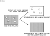
- FIG. 1 schematically illustrates an overview of images generated by a display apparatus according to a first embodiment of the present disclosure.
- the display apparatus according to the present embodiment is, for example, a projector.
- the display apparatus according to the present embodiment includes a light intensity modulator that performs intensity modulation on illumination light from an illuminator according to the present embodiment to generate an image (a projection image).
- the illumination light is generated by an illumination optical system (the illuminator) utilizing a spatial optical phase modulator such as an SLM (Spatial Light Modulator) as a diffractor.
- a spatial optical phase modulator such as an SLM (Spatial Light Modulator) as a diffractor.
- SDR Standard Dynamic Range
- HDR High Dynamic Range
- the SDR illumination light and the HDR illumination light are generated by distributing the light from a single light source section with use of a single diffractor.
- the threshold for determining the high and low of the luminance level of the image can be freely set. Depending on how the threshold is determined, a distribution ratio between the SDR illumination light and the HDR illumination light can be varied freely.
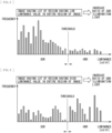
- FIG. 2 schematically illustrates a first example of a histogram of luminance values of an image generated by the display apparatus according to the first embodiment.
- FIG. 3 schematically illustrates a second example of the histogram of the luminance values of the image generated by the display apparatus according to the first embodiment.
- FIG. 2 illustrates an example of a histogram in a case where there are many pixels with a low luminance value in an image as a whole.
- FIG. 3 illustrates an example of a histogram in a case where there are many pixels with a high luminance value in an image as a whole.
- determination as to whether the image as a whole is an image having a high luminance level or an image having a low luminance level can be made by determining, with the threshold as a border, which of a frequency of pixels having a luminance value lower than the threshold or a frequency of pixels having a luminance value higher than the threshold is greater.
- the method of determining the threshold may be fixed to a certain value. However, the method of determining the threshold may be varied depending on the image.
- the brightness of the image as a whole is maintained by increasing the ratio of the light amount of the SDR illumination light in an image having a lot of region having a low luminance value in the entire region of the image.
- higher peak luminance can be achieved by increasing a ratio of the amount of light used as the HDR illumination light, in an image having a lot of region having a high luminance value in the image as a whole.
- the method of determining the light amount ratio between the SDR illumination light and the HDR illumination light may be set with reference to the histogram of the luminance values as illustrated in FIGs. 2 and 3 .
- the HDR illumination light is generated with diffracted light from the diffractor (optical phase modulator) as will be described later. Therefore, diffraction loss is unavoidable.
- the illuminator according to the present embodiment in a case of setting the light amount ratio between the SDR illumination light and the HDR illumination light, it is also possible to set it to a light amount ratio taking into consideration the diffraction loss. As an example, consider a case where 50% diffraction loss is caused. In a case where the light amount ratio between the SDR illumination light and the HDR illumination light is to be a ratio of 1:1 on a screen, the distribution ratio between the SDR illumination light and the HDR illumination light is set to 1:2 in advance.
- the illuminator according to the present embodiment it is also possible to set the distribution ratio between the SDR illumination light and the HDR illumination light taking into consideration the diffraction loss. It goes without saying that, in a case where transmission efficiency of the optical devices between the diffractor and the screen differs between the SDR illumination light and the HDR illumination light, the distribution ratio can be set to offset such a difference.
- FIG. 4 schematically illustrates an example of an overall configuration of the illuminator and the display apparatus according to the first embodiment.
- FIG. 4 illustrates a configuration example of a projector 101 including the illuminator according to the first embodiment, as an example of the display apparatus according to the first embodiment. Note that FIG. 4 illustrates the configuration example in a case of performing single color image display for simplification. However, in a case of displaying a color image, the configuration needs to include an illuminator corresponding to, for example, three colors of red, green, and blue.
- first illumination light in the technology of the present disclosure is the SDR illumination light and second illumination light in the technology of the present disclosure is the HDR illumination light. Further, a description is given of an example case where a first polarization component in the technology of the present disclosure is S-polarized light, and a second polarization component in the technology of the present disclosure is P-polarized light.
- the projector 101 includes an image signal output device 60, an intensity modulation pattern calculation circuit 61, a diffraction pattern calculation circuit 62, a diffractor drive circuit 63, a light intensity modulator drive circuit 64, a polarization ratio and light amount ratio calculating section 4, and a rotation angle control drive circuit 67.
- the polarization ratio and light amount ratio calculating section 4 includes a luminance threshold setting circuit 65 and a rotation angle calculation circuit 66.
- the projector 101 includes a diffractor 1, a light source section 30, a light intensity modulator 51, and a projection lens 53.
- a part that generates illumination light for the light intensity modulator 51 mainly, the light source section 30, the diffractor 1, and a circuit configuration part related to driving thereof correspond to one specific example of the illuminator in the technology of the present disclosure.
- the light source section 30 has a light source 31, a half-wave retarder 2, and a half-wave retarder rotation mechanism 3.
- the half-wave retarder 2 is a component which light emitted from the light source 31 enters.
- the half-wave retarder rotation mechanism 3 rotates the half-wave retarder 2.
- the half-wave retarder 2 corresponds to one specific example of a first half-wave retarder in the technology of the present disclosure.
- the light source section 30 emits light that includes the first polarization component (the S-polarized light) and the second polarization component (the P-polarized light) that differ in polarization direction from each other.
- the light source section 30 has a configuration in which the polarization ratio between the S-polarized light and the P-polarized light is allowed to be varied by rotating the half-wave retarder 2.
- the light source 31 be a light source that emits coherent light with high coherence like a laser.
- the light source 31 may be a light source such as an LED (Light Emitting Diode), a phosphor light source, or a lamp.
- LED Light Emitting Diode
- a phosphor light source or a lamp.
- the light source 31 be shaped to have a size same as that of the light intensity modulator 51 or to have a size that can include the light intensity modulator 51. If the light intensity modulator 51 is larger in aperture size than the diffractor 1, it is preferable to put an optical system expanding a beam diameter between the diffractor 1 and the light intensity modulator 51.
- the light intensity modulator 51 performs intensity modulation on the illumination light to generate an image.
- the light intensity modulator 51 is, for example, a DMD (Digital Micromirror Device).
- the light intensity modulator 51 may be, for example, a transmissive or reflective liquid crystal display device. Note that, FIG. 4 illustrates an example case where the light intensity modulator 51 is the reflective light intensity modulator.
- the diffractor 1 is, for example, a transmissive or reflective optical phase modulator. Note that FIG. 4 illustrates an example case where the diffractor 1 is a transmissive optical phase modulator.
- the diffractor 1 generates the SDR illumination light and the HDR illumination light on the basis of the light emitted from the light source section 30, and emits them.
- the SDR illumination light is used in the light intensity modulator 51 to generate an image in a first luminance region (low luminance region).
- the HDR illumination light is used in the light intensity modulator 51 to generate an image in a second luminance region (high luminance region) having luminance higher than that in the first luminance region.
- the diffractor 1 emits, as the SDR illumination light, light of the first polarization component (the S-polarized light) of the light emitted from the light source section 30 without performing phase modulation. Further, the diffractor 1 performs phase modulation on light of the second polarization component (the P-polarized light) of the light emitted from the light source section 30 on the basis of the image in the high luminance region, and emits the light as the HDR illumination light.
- the image signal output device 60 divides the received image signal into two image signals, and supplies the two image signals to the intensity modulation pattern calculation circuit 61 and the luminance threshold setting circuit 65.
- the luminance threshold setting circuit 65 sets a threshold used to determine whether it is an image having a high luminance level (an image in the high luminance region) or an image having a low luminance level (an image in the low luminance region), as illustrated in FIGs. 2 and 3 .
- a threshold used to determine whether it is an image having a high luminance level (an image in the high luminance region) or an image having a low luminance level (an image in the low luminance region), as illustrated in FIGs. 2 and 3 .
- an image signal from which a region having a luminance level equal to or higher than the threshold set by the luminance threshold setting circuit 65 is extracted is used as an HDR illumination light image signal.
- the diffraction pattern calculation circuit 62 calculates, on the basis of the HDR illumination light image signal, a diffraction pattern to be displayed at the diffractor 1.
- the diffraction pattern displayed at the diffractor 1 is a diffraction pattern that allows for formation of an illumination image having a luminance distribution in accordance with the image in the high luminance region to be displayed at the light intensity modulator 51.
- the diffraction pattern calculation circuit 62 calculates, for example, the diffraction pattern by repeatedly performing FFT (Fast Fourier Transform) calculation. Further, the diffraction pattern calculation circuit 62 supplies an illumination light intensity modulation pattern signal to the intensity modulation pattern calculation circuit 61.
- the illumination light intensity modulation pattern signal represents information of the luminance distribution of the illumination image formed with use of the diffraction pattern.
- the diffractor drive circuit 63 drives the diffractor 1 to display the diffraction pattern calculated by the diffraction pattern calculation circuit 62.
- the intensity modulation pattern calculation circuit 61 calculates, on the basis of the image signal, an intensity modulation pattern for generating an image to be displayed at the light intensity modulator 51. At this time, the intensity modulation pattern calculation circuit 61 calculates an intensity modulation pattern taking into consideration the information of the luminance distribution of the illumination image derived from the diffractor 1.
- the light intensity modulator drive circuit 64 so drives the light intensity modulator 51 as to generate the intensity modulation pattern calculated by the intensity modulation pattern calculation circuit 61.
- the light intensity modulator 51 Applied to the light intensity modulator 51 via the diffractor 1 are the SDR illumination light and the HDR illumination light as the illumination light.
- the light intensity modulator 51 performs intensity modulation on the applied illumination light on the basis of the intensity modulation pattern calculated by the intensity modulation pattern calculation circuit 61, and generates a projection image.
- the information of the luminance distribution of the illumination image derived from the diffractor 1 is taken into consideration in the intensity modulation pattern calculated by the intensity modulation pattern calculation circuit 61. Therefore, the light intensity modulator 51 generates a projection image that reproduces the original image signal as a result.
- the projection image generated by the light intensity modulator 51 is emitted toward the projection lens 53.
- the projection lens 53 is a projection optical system including a plurality of lenses.
- the projection lens 53 projects the projection image generated by the light intensity modulator 51 onto an unillustrated projection surface such as a screen.
- the polarization ratio and light amount ratio calculating section 4 determines the polarization ratio of the light source section 30 on the basis of the image signal.
- the polarization ratio and light amount ratio calculating section 4 so determines the polarization ratio between the S-polarized light and the P-polarized light that the light amount of the SDR illumination light becomes a light amount based on a ratio of the image in the low luminance region included in the image signal, and the light amount of the HDR illumination light becomes a light amount based on a ratio of the image in the high luminance region included in the image signal.
- the polarization ratio and light amount ratio calculating section 4 may so determine the polarization ratio that the light amount ratio between the light amount of the SDR illumination light and the light amount of the HDR illumination light becomes a value taking into consideration a shooting mode used upon generation of the image signal.
- the polarization ratio and light amount ratio calculating section 4 may so determine the polarization ratio that the light amount ratio between the light amount of the SDR illumination light and the light amount of the HDR illumination light becomes a value taking into consideration the light amount loss caused upon the phase modulation performed by the diffractor 1.
- the rotation angle calculation circuit 66 calculates a rotation angle of the half-wave retarder 2 that allows for the polarization ratio determined by the polarization ratio and light amount ratio calculating section 4. Thus, the rotation angle of the half-wave retarder 2 for optimizing the light amount ratio between the SDR illumination light and the HDR illumination light is calculated.
- the rotation angle control drive circuit 67 so controls the half-wave retarder rotation mechanism 3 that the rotation angle of the half-wave retarder 2 becomes the rotation angle calculated by the rotation angle calculation circuit 66.
- the configurations of a circuit processing an image signal, a drive circuit, and the like may be substantially similar to those of the projector 101 in FIG. 4 .
- parts substantially the same as those of the projector 101 in FIG. 4 are denoted by the same reference numerals, and descriptions thereof will be omitted as appropriate.
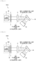
- FIG. 5 schematically illustrates a configuration of a main part of a projector 101A according to a first configuration example of the first embodiment.
- the projector 101A describes a configuration example in a case where the diffractor 1 is a transmissive diffractor 1T (a transmissive optical phase modulator), and the light intensity modulator 51 is a DMD 52 (a reflective light intensity modulator).
- the transmissive diffractor 1T is, for example, a transmissive liquid crystal display device.
- the light source 31 be a light source that emits coherent light with high coherence like a laser.
- the transmissive diffractor 1T is a diffractor that performs phase modulation only on the P-polarized light
- the S-polarized light of the entering light is transmitted as it is without undergoing phase modulation.
- This transmitted light becomes the SDR illumination light.
- the P-polarized light component is subjected to phase modulation with the desired diffraction pattern and becomes the HDR illumination light.
- FIG. 6 schematically illustrates a configuration of a main part of a projector 101B according to a second configuration example of the first embodiment.
- the projector 101B according to the second configuration example includes a light source section 30A instead of the light source section 30 in the projector 101A according to the first configuration example illustrated in FIG. 5 .
- the light source section 30A includes the light source 31, the PS converter 22, and the half-wave retarder 2.
- the light source 31 is not limited to a light source that emits coherent light with high coherence like a laser.
- the light source 31 may be a light source such as an LED, a phosphor light source, or a lamp.
- the LED, the phosphor light source, the lamp, or the like as the light source 31, as in the projector 101B according to the second configuration example it is preferable to additionally insert the optical device that aligns polarized light in one direction, for example, the PS converter 22, between the light source 31 and the half-wave retarder 2.
- FIG. 7 schematically illustrates a configuration of a main part of a projector 101C according to a third configuration example of the first embodiment.
- the projector 101C according to the third configuration example describes a configuration example in a case where the diffractor 1 is a reflective diffractor 1R (a reflective optical phase modulator), and the light intensity modulator 51 is the DMD 52 (a reflective light intensity modulator).
- the reflective diffractor 1R is, for example, a reflective liquid crystal display device.
- a wire grid polarizer 54 be disposed in front of the reflective diffractor 1R.
- a surface of the reflective diffractor 1R be provided with a polarization-separation coating that highly reflects the S-polarized light and highly transmits the P-polarized light. As a result, an improvement in light use efficiency is expectable.
- the light source section 30 may be configured by the light source section 30A including a PS converter 32, as with the projector 101B illustrated in FIG. 6 .
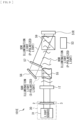
- FIG. 8 schematically illustrates a configuration of a main part of a projector 101D according to a fourth configuration example of the first embodiment.
- the projector 101D according to the fourth configuration example describes a configuration example in a case where the diffractor 1 is the transmissive diffractor 1T (a transmissive optical phase modulator), and the light intensity modulator 51 is a transmissive liquid crystal display device 51T (a transmissive light intensity modulator).
- the transmissive diffractor 1T is, for example, a transmissive liquid crystal display device.
- the projector 101D includes a polarization beam splitter 55, a reflection mirror 56, a half-wave retarder 57, and an analyzer 58.
- the half-wave retarder 57 corresponds to one specific example of the second half-wave retarder in the technology of the present disclosure.
- the analyzer 58 is disposed between the transmissive liquid crystal display device 51T and the projection lens 53.
- the polarization beam splitter 55 is an optical path separator that separates the optical path of the SDR illumination light emitted from the transmissive diffractor 1T and the optical path of the HDR illumination light emitted from the transmissive diffractor 1T.
- the half-wave retarder 57 is disposed on one of the optical path of the SDR illumination light and the optical path of the HDR illumination light.
- the light intensity modulator 51 is the transmissive liquid crystal display device 51T
- a device that performs separation on the basis of polarization for example, the polarization beam splitter 55
- the polarization beam splitter 55 is disposed between the transmissive diffractor 1T and the transmissive liquid crystal display device 51T to separate the optical path of the SDR illumination light and the optical path of the HDR illumination light.
- the half-wave retarder 57 is disposed on one of the optical path of the SDR illumination light and the optical path of the HDR illumination light. Thereby, one of the polarized lights is rotated by 90°. This makes it possible to align the polarization of the SDR illumination light and the polarization of the HDR illumination light.
- the half-wave retarder 57 is disposed on the optical path of the SDR illumination light to convert the SDR illumination light from the S-polarized light into the P-polarized light.
- the half-wave retarder 57 may be disposed on the optical path of the HDR illumination light to convert the HDR illumination light from the P-polarized light into the S-polarized light.
- the projector 101D it is necessary to spatially separate the SDR illumination light and the HDR illumination light once by the polarization beam splitter 55 or the like. However, thereafter, it is preferable to so synthesize the SDR illumination light and the HDR illumination light on the transmissive liquid crystal display device 51T at an angle as shallow as possible that the SDR illumination light and the HDR illumination light are included within an acceptable angular range in the optical system from the transmissive liquid crystal display device 51T to the projection lens 53.
- the light source section 30 may be configured by the light source section 30A including the PS converter 32, as with the projector 101B illustrated in FIG. 6 .
- FIG. 9 schematically illustrates a configuration of a main part of a projector 101E according to a fifth configuration example of the first embodiment.
- the projector 101E according to the fifth configuration example describes a configuration example in a case where the diffractor 1 is the transmissive diffractor 1T (a transmissive optical phase modulator), and the light intensity modulator 51 is a reflective liquid crystal display device 51R (a reflective light intensity modulator).
- the transmissive diffractor 1T is, for example, a transmissive liquid crystal display device.
- the projector 101E includes the polarization beam splitter 55, the reflection mirror 56, the half-wave retarder 57, and a polarization beam splitter 59.
- the half-wave retarder 57 corresponds to one specific example of the second half-wave retarder in the technology of the present disclosure.
- the polarization beam splitter 59 is disposed in front of the reflective liquid crystal display device 51R.
- the polarization beam splitter 55 is an optical path separator that separates the optical path of the SDR illumination light emitted from the transmissive diffractor 1T and the optical path of the HDR illumination light emitted from the transmissive diffractor 1T.
- the half-wave retarder 57 is disposed on one of the optical path of the SDR illumination light and the optical path of the HDR illumination light.
- the light intensity modulator 51 is the reflective liquid crystal display device 51R
- the polarization beam splitter 55 is disposed between the transmissive diffractor 1T and the reflective liquid crystal display device 51R to separate the optical path of the SDR illumination light and the optical path of the HDR illumination light.
- the half-wave retarder 57 is disposed on one of the optical path of the SDR illumination light and the optical path of the HDR illumination light. Thereby, one of the polarized lights is rotated by 90°. This makes it possible to align the polarization of the SDR illumination light and the polarization of the HDR illumination light.
- the half-wave retarder 57 is disposed on the optical path of the SDR illumination light to convert the SDR illumination light from the S-polarized light into the P-polarized light.
- the half-wave retarder 57 may be disposed on the optical path of the HDR illumination light to convert the HDR illumination light from the P-polarized light into the S-polarized light.
- the projector 101E it is necessary to spatially separate the SDR illumination light and the HDR illumination light once by the polarization beam splitter 55 or the like. However, thereafter, it is preferable to so synthesize the SDR illumination light and the HDR illumination light on the reflective liquid crystal display device 51R at an angle as shallow as possible that the SDR illumination light and the HDR illumination light are included within an acceptable angular range in the optical system from the reflective liquid crystal display device 51R to the projection lens 53.
- the light source section 30 may be configured by the light source section 30A including the PS converter 32, as with the projector 101B illustrated in FIG. 6 .
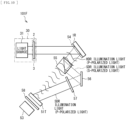
- FIG. 10 schematically illustrates a configuration of a main part of a projector 101F according to a sixth configuration example of the first embodiment.
- the projector 101F according to the sixth configuration example describes a configuration example in a case where the diffractor 1 is the reflective diffractor 1R (a reflective optical phase modulator), and the light intensity modulator 51 is the transmissive liquid crystal display device 51T (a transmissive light intensity modulator).
- the reflective diffractor 1R is, for example, a reflective liquid crystal display device.
- the wire grid polarizer 54 be disposed in front of the reflective diffractor 1R.
- a surface of the reflective diffractor 1R be provided with a polarization-separation coating that highly reflects the S-polarized light and highly transmits the P-polarized light. As a result, an improvement in light use efficiency is expectable.
- the light source section 30 may be configured by the light source section 30A including the PS converter 32, as with the projector 101B illustrated in FIG. 6 .
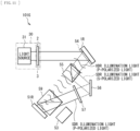
- FIG. 11 schematically illustrates a configuration of a main part of a projector 101G according to a seventh configuration example of the first embodiment.
- the projector 101G according to the seventh configuration example describes a configuration example in a case where the diffractor 1 is the reflective diffractor 1R (a reflective optical phase modulator), and the light intensity modulator 51 is the reflective liquid crystal display device 51R (a reflective light intensity modulator).
- the reflective diffractor 1R is, for example, a reflective liquid crystal display device.
- the wire grid polarizer 54 be disposed in front of the reflective diffractor 1R.
- a surface of the reflective diffractor 1R be provided with a polarization-separation coating that highly reflects the S-polarized light and highly transmits the P-polarized light. As a result, an improvement in light use efficiency is expectable.
- the light source section 30 may be configured by the light source section 30A including the PS converter 32, as with the projector 101B illustrated in FIG. 6 .
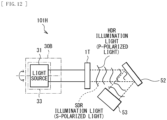
- FIG. 12 schematically illustrates a configuration of a main part of a projector 101H according to an eighth configuration example of the first embodiment.
- the projector 101H according to the eighth configuration example includes a light source section 30B instead of the light source section 30 in the projector 101A according to the first configuration example illustrated in FIG. 5 .
- the light source section 30B includes the light source 31 and a light source rotation mechanism 33 that rotates the light source 31.
- the light source 31 instead of rotating the half-wave retarder 2, the light source 31 itself is rotated around the optical axis. This adjusts the light amount ratio between the SDR illumination light and the HDR illumination light.
- the light source 31 emits linearly polarized light.
- the half-wave retarder 2 in the light source section 30 can be omitted in the projector 101H according to the eighth configuration example.
- the light emitted from the light source 31 needs to be linearly polarized. Therefore, for example, in a case of randomly polarized light, it is necessary to incorporate an optical device that aligns the polarization directions in the light source 31. Further, it is necessary to illuminate the entire surface of the transmissive diffractor 1T at any rotation angle. Therefore, the exit beam size of the light source 31 needs to be slightly larger than the transmissive diffractor 1T.
- the configuration example in FIG. 12 is a modification of the configuration example in FIG. 5 .
- the configuration examples in FIGs. 7 to 11 can also have a configuration in which the half-wave retarder 2 is removed and the light source 31 itself is rotated.
- 30B may be configured by the light source section 30A including the PS converter 32, as with the projector 101B illustrated in FIG. 6 .
- the light from the single light source section is distributed at a freely-set ratio, and the SDR illumination light and the HDR illumination light are generated together by the diffractor (optical phase modulator). This makes it unnecessary to provide more than one light source section, making the optical system very simple.
- the illuminator and the display apparatus it is possible to change the light amount distribution rate in accordance with each frame of the projection image. Consequently, for example, in a scene with no region having a high luminance level, all of the light can be used as the SDR illumination light. In contrast, in a scene, such as a star sky, in which shiny parts are scattered in a totally dark scene, all of the light can be used as the HDR illumination light. This results in high peak luminance. This also improves insufficient blackness in the black region that is degraded by an influence of slight leakage of light at the light intensity modulator. Thus, the distribution ratio between the SDR illumination light and the HDR illumination light can be freely varied in accordance with the scene. Consequently, it is possible to achieve an image having high-peak luminance and a high contrast.
- the technology according to the present embodiment is higher in efficiency for the amount of the diffraction loss of the SDR illumination light.
Landscapes
- Physics & Mathematics (AREA)
- General Physics & Mathematics (AREA)
- Engineering & Computer Science (AREA)
- Optics & Photonics (AREA)
- Multimedia (AREA)
- Signal Processing (AREA)
- Nonlinear Science (AREA)
- Theoretical Computer Science (AREA)
- Computer Hardware Design (AREA)
- Crystallography & Structural Chemistry (AREA)
- Chemical & Material Sciences (AREA)
- Projection Apparatus (AREA)
- Transforming Electric Information Into Light Information (AREA)
- Liquid Crystal (AREA)
Applications Claiming Priority (2)
| Application Number | Priority Date | Filing Date | Title |
|---|---|---|---|
| JP2018162309 | 2018-08-31 | ||
| PCT/JP2019/031308 WO2020045025A1 (ja) | 2018-08-31 | 2019-08-08 | 照明装置、および表示装置 |
Publications (3)
| Publication Number | Publication Date |
|---|---|
| EP3845964A1 EP3845964A1 (en) | 2021-07-07 |
| EP3845964A4 EP3845964A4 (en) | 2021-11-10 |
| EP3845964B1 true EP3845964B1 (en) | 2024-10-09 |
Family
ID=69644210
Family Applications (1)
| Application Number | Title | Priority Date | Filing Date |
|---|---|---|---|
| EP19853360.6A Active EP3845964B1 (en) | 2018-08-31 | 2019-08-08 | Illumination device and display device |
Country Status (6)
| Country | Link |
|---|---|
| US (1) | US11153541B2 (enExample) |
| EP (1) | EP3845964B1 (enExample) |
| JP (1) | JP7314946B2 (enExample) |
| KR (1) | KR20210048495A (enExample) |
| CN (1) | CN112585532B (enExample) |
| WO (1) | WO2020045025A1 (enExample) |
Families Citing this family (8)
| Publication number | Priority date | Publication date | Assignee | Title |
|---|---|---|---|---|
| CN111443491A (zh) * | 2020-04-30 | 2020-07-24 | 京东方科技集团股份有限公司 | 一种光学显示系统及控制方法、显示装置 |
| JP7635977B2 (ja) * | 2021-03-26 | 2025-02-26 | 国立大学法人 奈良先端科学技術大学院大学 | 調光装置 |
| US20230314846A1 (en) * | 2022-03-31 | 2023-10-05 | Meta Platforms Technologies, Llc | Configurable multifunctional display panel |
| TW202401126A (zh) * | 2022-05-25 | 2024-01-01 | 日商索尼集團公司 | 圖像顯示裝置 |
| KR20240073449A (ko) * | 2022-11-18 | 2024-05-27 | 삼성전자주식회사 | 디스플레이 장치 및 그 구동 방법 |
| US20250117993A1 (en) * | 2023-10-05 | 2025-04-10 | Adobe Inc. | High dynamic range digital image editing visualizations |
| WO2025196296A1 (en) | 2024-03-21 | 2025-09-25 | Barco N.V. | Light steering system, method for producing an illumination field of steered polarized light, and hybrid projector using the same |
| LU103269B1 (en) * | 2024-03-21 | 2025-09-22 | Barco Nv | Light steering system, method for producing an illumination field of steered polarized light, and hybrid projector using the same |
Citations (1)
| Publication number | Priority date | Publication date | Assignee | Title |
|---|---|---|---|---|
| US20170085846A1 (en) * | 2014-06-03 | 2017-03-23 | Mtt Innovation Incorporated | Efficient, dynamic, high contrast lensing with applications to imaging, illumination and projection |
Family Cites Families (25)
| Publication number | Priority date | Publication date | Assignee | Title |
|---|---|---|---|---|
| FR2803968B1 (fr) * | 2000-01-17 | 2002-05-31 | Ct Scient Tech Batiment Cstb | Procede et dispositif de restitution d'un signal lumineux |
| JP4776785B2 (ja) * | 2001-01-12 | 2011-09-21 | キヤノン株式会社 | 投射型表示装置 |
| WO2002069030A2 (en) * | 2001-02-27 | 2002-09-06 | The University Of British Columbia | High dynamic range display devices |
| US8687271B2 (en) * | 2002-03-13 | 2014-04-01 | Dolby Laboratories Licensing Corporation | N-modulation displays and related methods |
| JP2005234539A (ja) * | 2004-01-20 | 2005-09-02 | Seiko Epson Corp | 光学系の光伝搬構造、光学表示装置および光変調素子 |
| JP2005250235A (ja) * | 2004-03-05 | 2005-09-15 | Seiko Epson Corp | 光変調装置、光学表示装置、光変調制御プログラム及び光学表示装置制御プログラム、並びに光変調制御方法及び光学表示装置制御方法 |
| JP2005257872A (ja) * | 2004-03-10 | 2005-09-22 | Seiko Epson Corp | 照明装置及びプロジェクタ |
| JP2008083661A (ja) * | 2006-08-30 | 2008-04-10 | Olympus Corp | 照明装置およびそれを用いた画像投影装置 |
| CN101377571A (zh) * | 2007-08-28 | 2009-03-04 | 鸿富锦精密工业(深圳)有限公司 | 立体投影光学系统 |
| CN101226325B (zh) * | 2008-02-03 | 2010-06-02 | 李志扬 | 基于随机相长干涉的三维显示方法及装置 |
| JP2011151640A (ja) | 2010-01-22 | 2011-08-04 | Seiko Epson Corp | 投写位置補正装置、プロジェクター及び投写位置補正データ生成方法 |
| RU2559724C2 (ru) * | 2011-04-19 | 2015-08-10 | Долби Лабораторис Лайсэнзин Корпорейшн | Проекционные дисплеи с высокой светимостью и связанные способы |
| JP5935679B2 (ja) * | 2012-04-02 | 2016-06-15 | ソニー株式会社 | 照明装置および表示装置 |
| US8976318B2 (en) * | 2013-03-14 | 2015-03-10 | Christie Digital Systems Usa Inc. | System and method for zonal switching for light steering to produce an image having high dynamic range |
| US10368044B2 (en) * | 2013-10-10 | 2019-07-30 | Dolby Laboratories Licensing Corporation | Displaying DCI and other content on an enhanced dynamic range projector |
| JP6634012B2 (ja) * | 2013-10-20 | 2020-01-22 | エムティティ イノベーション インコーポレイテッドMtt Innovation Incorporated | 光照射野プロジェクタおよび方法 |
| US20150124330A1 (en) * | 2013-11-04 | 2015-05-07 | Christie Digital Systems Canada Inc. | Relay lens system for a high dynamic range projector |
| WO2015073838A1 (en) * | 2013-11-15 | 2015-05-21 | Reald Inc. | High dynamic range, high contrast projection systems |
| WO2015172236A1 (en) | 2014-05-15 | 2015-11-19 | Mtt Innovation Incorporated | Optimizing drive schemes for multiple projector systems |
| CN105227941A (zh) * | 2014-06-18 | 2016-01-06 | 深圳市绎立锐光科技开发有限公司 | 一种投影控制系统 |
| EP3034499A1 (en) | 2014-12-17 | 2016-06-22 | Gilead Sciences, Inc. | Novel FXR (NR1H4) modulating compounds |
| JP6503816B2 (ja) | 2015-03-20 | 2019-04-24 | セイコーエプソン株式会社 | プロジェクター |
| JP6757157B2 (ja) * | 2016-03-29 | 2020-09-16 | キヤノン株式会社 | 投影装置およびその制御方法 |
| WO2018141407A1 (en) * | 2017-02-03 | 2018-08-09 | Barco N.V. | System and method for enhanced image projection |
| US11368217B2 (en) * | 2017-08-01 | 2022-06-21 | Nec Corporation | Receiving device, communication system, receiving method, and composite image generation program |
-
2019
- 2019-08-08 US US17/267,111 patent/US11153541B2/en active Active
- 2019-08-08 CN CN201980054802.1A patent/CN112585532B/zh active Active
- 2019-08-08 EP EP19853360.6A patent/EP3845964B1/en active Active
- 2019-08-08 JP JP2020540220A patent/JP7314946B2/ja active Active
- 2019-08-08 KR KR1020217005034A patent/KR20210048495A/ko not_active Withdrawn
- 2019-08-08 WO PCT/JP2019/031308 patent/WO2020045025A1/ja not_active Ceased
Patent Citations (1)
| Publication number | Priority date | Publication date | Assignee | Title |
|---|---|---|---|---|
| US20170085846A1 (en) * | 2014-06-03 | 2017-03-23 | Mtt Innovation Incorporated | Efficient, dynamic, high contrast lensing with applications to imaging, illumination and projection |
Also Published As
| Publication number | Publication date |
|---|---|
| US11153541B2 (en) | 2021-10-19 |
| WO2020045025A1 (ja) | 2020-03-05 |
| JP7314946B2 (ja) | 2023-07-26 |
| CN112585532B (zh) | 2022-08-30 |
| CN112585532A (zh) | 2021-03-30 |
| EP3845964A4 (en) | 2021-11-10 |
| US20210168340A1 (en) | 2021-06-03 |
| EP3845964A1 (en) | 2021-07-07 |
| JPWO2020045025A1 (ja) | 2021-08-26 |
| KR20210048495A (ko) | 2021-05-03 |
Similar Documents
| Publication | Publication Date | Title |
|---|---|---|
| EP3845964B1 (en) | Illumination device and display device | |
| RU2559724C2 (ru) | Проекционные дисплеи с высокой светимостью и связанные способы | |
| JP6788504B2 (ja) | マルチプルプロジェクタシステムのための駆動スキームの最適化 | |
| JP5512798B2 (ja) | 高ダイナミックレンジ投影システム | |
| EP3066829B1 (en) | Single and multi-modulator projector systems with global dimming | |
| US11381790B2 (en) | Display system, video processing device, pixel shift display device, video processing method, display method, and program | |
| US11061310B2 (en) | Projector with improved contrast | |
| CA2909635C (en) | Multi-half-tone imaging and dual modulation projection/dual modulation laser projection | |
| US20120105807A1 (en) | Laser projector compatible with wavelength multiplexing passive filter techniques for stereoscopic 3D | |
| EP3495883B1 (en) | Projection-type display apparatus | |
| WO2020100695A1 (ja) | 画像表示装置 | |
| JP7790436B2 (ja) | 照明装置 | |
| CN117651908A (zh) | 照明装置 | |
| HK1227205A1 (en) | High luminance projection displays and associated methods |
Legal Events
| Date | Code | Title | Description |
|---|---|---|---|
| STAA | Information on the status of an ep patent application or granted ep patent |
Free format text: STATUS: THE INTERNATIONAL PUBLICATION HAS BEEN MADE |
|
| STAA | Information on the status of an ep patent application or granted ep patent |
Free format text: STATUS: REQUEST FOR EXAMINATION WAS MADE |
|
| PUAI | Public reference made under article 153(3) epc to a published international application that has entered the european phase |
Free format text: ORIGINAL CODE: 0009012 |
|
| 17P | Request for examination filed |
Effective date: 20210207 |
|
| AK | Designated contracting states |
Kind code of ref document: A1 Designated state(s): AL AT BE BG CH CY CZ DE DK EE ES FI FR GB GR HR HU IE IS IT LI LT LU LV MC MK MT NL NO PL PT RO RS SE SI SK SM TR |
|
| RAP3 | Party data changed (applicant data changed or rights of an application transferred) |
Owner name: SONY GROUP CORPORATION |
|
| A4 | Supplementary search report drawn up and despatched |
Effective date: 20211011 |
|
| RIC1 | Information provided on ipc code assigned before grant |
Ipc: H04N 9/31 20060101ALI20211005BHEP Ipc: H04N 5/74 20060101ALI20211005BHEP Ipc: G09G 3/36 20060101ALI20211005BHEP Ipc: G09G 3/34 20060101ALI20211005BHEP Ipc: G09G 3/20 20060101ALI20211005BHEP Ipc: G02F 1/01 20060101ALI20211005BHEP Ipc: G02B 27/28 20060101ALI20211005BHEP Ipc: G02B 26/08 20060101ALI20211005BHEP Ipc: G02B 5/30 20060101ALI20211005BHEP Ipc: G02B 5/18 20060101ALI20211005BHEP Ipc: G03B 21/14 20060101AFI20211005BHEP |
|
| DAV | Request for validation of the european patent (deleted) | ||
| DAX | Request for extension of the european patent (deleted) | ||
| GRAP | Despatch of communication of intention to grant a patent |
Free format text: ORIGINAL CODE: EPIDOSNIGR1 |
|
| STAA | Information on the status of an ep patent application or granted ep patent |
Free format text: STATUS: GRANT OF PATENT IS INTENDED |
|
| INTG | Intention to grant announced |
Effective date: 20240514 |
|
| GRAS | Grant fee paid |
Free format text: ORIGINAL CODE: EPIDOSNIGR3 |
|
| GRAA | (expected) grant |
Free format text: ORIGINAL CODE: 0009210 |
|
| STAA | Information on the status of an ep patent application or granted ep patent |
Free format text: STATUS: THE PATENT HAS BEEN GRANTED |
|
| P01 | Opt-out of the competence of the unified patent court (upc) registered |
Free format text: CASE NUMBER: APP_48129/2024 Effective date: 20240821 |
|
| AK | Designated contracting states |
Kind code of ref document: B1 Designated state(s): AL AT BE BG CH CY CZ DE DK EE ES FI FR GB GR HR HU IE IS IT LI LT LU LV MC MK MT NL NO PL PT RO RS SE SI SK SM TR |
|
| REG | Reference to a national code |
Ref country code: CH Ref legal event code: EP |
|
| REG | Reference to a national code |
Ref country code: DE Ref legal event code: R096 Ref document number: 602019060239 Country of ref document: DE |
|
| REG | Reference to a national code |
Ref country code: IE Ref legal event code: FG4D |
|
| REG | Reference to a national code |
Ref country code: LT Ref legal event code: MG9D |
|
| REG | Reference to a national code |
Ref country code: NL Ref legal event code: MP Effective date: 20241009 |
|
| REG | Reference to a national code |
Ref country code: AT Ref legal event code: MK05 Ref document number: 1731230 Country of ref document: AT Kind code of ref document: T Effective date: 20241009 |
|
| PG25 | Lapsed in a contracting state [announced via postgrant information from national office to epo] |
Ref country code: NL Free format text: LAPSE BECAUSE OF FAILURE TO SUBMIT A TRANSLATION OF THE DESCRIPTION OR TO PAY THE FEE WITHIN THE PRESCRIBED TIME-LIMIT Effective date: 20241009 |
|
| PG25 | Lapsed in a contracting state [announced via postgrant information from national office to epo] |
Ref country code: NL Free format text: LAPSE BECAUSE OF FAILURE TO SUBMIT A TRANSLATION OF THE DESCRIPTION OR TO PAY THE FEE WITHIN THE PRESCRIBED TIME-LIMIT Effective date: 20241009 |
|
| PG25 | Lapsed in a contracting state [announced via postgrant information from national office to epo] |
Ref country code: HR Free format text: LAPSE BECAUSE OF FAILURE TO SUBMIT A TRANSLATION OF THE DESCRIPTION OR TO PAY THE FEE WITHIN THE PRESCRIBED TIME-LIMIT Effective date: 20241009 Ref country code: PT Free format text: LAPSE BECAUSE OF FAILURE TO SUBMIT A TRANSLATION OF THE DESCRIPTION OR TO PAY THE FEE WITHIN THE PRESCRIBED TIME-LIMIT Effective date: 20250210 Ref country code: IS Free format text: LAPSE BECAUSE OF FAILURE TO SUBMIT A TRANSLATION OF THE DESCRIPTION OR TO PAY THE FEE WITHIN THE PRESCRIBED TIME-LIMIT Effective date: 20250209 |
|
| PG25 | Lapsed in a contracting state [announced via postgrant information from national office to epo] |
Ref country code: FI Free format text: LAPSE BECAUSE OF FAILURE TO SUBMIT A TRANSLATION OF THE DESCRIPTION OR TO PAY THE FEE WITHIN THE PRESCRIBED TIME-LIMIT Effective date: 20241009 |
|
| PG25 | Lapsed in a contracting state [announced via postgrant information from national office to epo] |
Ref country code: BG Free format text: LAPSE BECAUSE OF FAILURE TO SUBMIT A TRANSLATION OF THE DESCRIPTION OR TO PAY THE FEE WITHIN THE PRESCRIBED TIME-LIMIT Effective date: 20241009 |
|
| PG25 | Lapsed in a contracting state [announced via postgrant information from national office to epo] |
Ref country code: ES Free format text: LAPSE BECAUSE OF FAILURE TO SUBMIT A TRANSLATION OF THE DESCRIPTION OR TO PAY THE FEE WITHIN THE PRESCRIBED TIME-LIMIT Effective date: 20241009 |
|
| PG25 | Lapsed in a contracting state [announced via postgrant information from national office to epo] |
Ref country code: NO Free format text: LAPSE BECAUSE OF FAILURE TO SUBMIT A TRANSLATION OF THE DESCRIPTION OR TO PAY THE FEE WITHIN THE PRESCRIBED TIME-LIMIT Effective date: 20250109 |
|
| PG25 | Lapsed in a contracting state [announced via postgrant information from national office to epo] |
Ref country code: LV Free format text: LAPSE BECAUSE OF FAILURE TO SUBMIT A TRANSLATION OF THE DESCRIPTION OR TO PAY THE FEE WITHIN THE PRESCRIBED TIME-LIMIT Effective date: 20241009 Ref country code: GR Free format text: LAPSE BECAUSE OF FAILURE TO SUBMIT A TRANSLATION OF THE DESCRIPTION OR TO PAY THE FEE WITHIN THE PRESCRIBED TIME-LIMIT Effective date: 20250110 Ref country code: AT Free format text: LAPSE BECAUSE OF FAILURE TO SUBMIT A TRANSLATION OF THE DESCRIPTION OR TO PAY THE FEE WITHIN THE PRESCRIBED TIME-LIMIT Effective date: 20241009 |
|
| PG25 | Lapsed in a contracting state [announced via postgrant information from national office to epo] |
Ref country code: PL Free format text: LAPSE BECAUSE OF FAILURE TO SUBMIT A TRANSLATION OF THE DESCRIPTION OR TO PAY THE FEE WITHIN THE PRESCRIBED TIME-LIMIT Effective date: 20241009 |
|
| PG25 | Lapsed in a contracting state [announced via postgrant information from national office to epo] |
Ref country code: RS Free format text: LAPSE BECAUSE OF FAILURE TO SUBMIT A TRANSLATION OF THE DESCRIPTION OR TO PAY THE FEE WITHIN THE PRESCRIBED TIME-LIMIT Effective date: 20250109 |
|
| PG25 | Lapsed in a contracting state [announced via postgrant information from national office to epo] |
Ref country code: SM Free format text: LAPSE BECAUSE OF FAILURE TO SUBMIT A TRANSLATION OF THE DESCRIPTION OR TO PAY THE FEE WITHIN THE PRESCRIBED TIME-LIMIT Effective date: 20241009 |
|
| PG25 | Lapsed in a contracting state [announced via postgrant information from national office to epo] |
Ref country code: DK Free format text: LAPSE BECAUSE OF FAILURE TO SUBMIT A TRANSLATION OF THE DESCRIPTION OR TO PAY THE FEE WITHIN THE PRESCRIBED TIME-LIMIT Effective date: 20241009 |
|
| REG | Reference to a national code |
Ref country code: DE Ref legal event code: R097 Ref document number: 602019060239 Country of ref document: DE |
|
| PG25 | Lapsed in a contracting state [announced via postgrant information from national office to epo] |
Ref country code: EE Free format text: LAPSE BECAUSE OF FAILURE TO SUBMIT A TRANSLATION OF THE DESCRIPTION OR TO PAY THE FEE WITHIN THE PRESCRIBED TIME-LIMIT Effective date: 20241009 |
|
| PG25 | Lapsed in a contracting state [announced via postgrant information from national office to epo] |
Ref country code: RO Free format text: LAPSE BECAUSE OF FAILURE TO SUBMIT A TRANSLATION OF THE DESCRIPTION OR TO PAY THE FEE WITHIN THE PRESCRIBED TIME-LIMIT Effective date: 20241009 |
|
| PG25 | Lapsed in a contracting state [announced via postgrant information from national office to epo] |
Ref country code: SK Free format text: LAPSE BECAUSE OF FAILURE TO SUBMIT A TRANSLATION OF THE DESCRIPTION OR TO PAY THE FEE WITHIN THE PRESCRIBED TIME-LIMIT Effective date: 20241009 |
|
| PG25 | Lapsed in a contracting state [announced via postgrant information from national office to epo] |
Ref country code: CZ Free format text: LAPSE BECAUSE OF FAILURE TO SUBMIT A TRANSLATION OF THE DESCRIPTION OR TO PAY THE FEE WITHIN THE PRESCRIBED TIME-LIMIT Effective date: 20241009 |
|
| PG25 | Lapsed in a contracting state [announced via postgrant information from national office to epo] |
Ref country code: IT Free format text: LAPSE BECAUSE OF FAILURE TO SUBMIT A TRANSLATION OF THE DESCRIPTION OR TO PAY THE FEE WITHIN THE PRESCRIBED TIME-LIMIT Effective date: 20241009 |
|
| PLBE | No opposition filed within time limit |
Free format text: ORIGINAL CODE: 0009261 |
|
| STAA | Information on the status of an ep patent application or granted ep patent |
Free format text: STATUS: NO OPPOSITION FILED WITHIN TIME LIMIT |
|
| PG25 | Lapsed in a contracting state [announced via postgrant information from national office to epo] |
Ref country code: SE Free format text: LAPSE BECAUSE OF FAILURE TO SUBMIT A TRANSLATION OF THE DESCRIPTION OR TO PAY THE FEE WITHIN THE PRESCRIBED TIME-LIMIT Effective date: 20241009 |
|
| 26N | No opposition filed |
Effective date: 20250710 |
|
| PGFP | Annual fee paid to national office [announced via postgrant information from national office to epo] |
Ref country code: DE Payment date: 20250724 Year of fee payment: 7 |
|
| PGFP | Annual fee paid to national office [announced via postgrant information from national office to epo] |
Ref country code: FR Payment date: 20250725 Year of fee payment: 7 |