EP3845741A1 - Ölreservoirentlüftungsventil für ein flugzeugtriebwerk - Google Patents
Ölreservoirentlüftungsventil für ein flugzeugtriebwerk Download PDFInfo
- Publication number
- EP3845741A1 EP3845741A1 EP20201047.6A EP20201047A EP3845741A1 EP 3845741 A1 EP3845741 A1 EP 3845741A1 EP 20201047 A EP20201047 A EP 20201047A EP 3845741 A1 EP3845741 A1 EP 3845741A1
- Authority
- EP
- European Patent Office
- Prior art keywords
- tank
- oil reservoir
- oil
- air
- passage
- Prior art date
- Legal status (The legal status is an assumption and is not a legal conclusion. Google has not performed a legal analysis and makes no representation as to the accuracy of the status listed.)
- Granted
Links
Images


Classifications
-
- B—PERFORMING OPERATIONS; TRANSPORTING
- B64—AIRCRAFT; AVIATION; COSMONAUTICS
- B64D—EQUIPMENT FOR FITTING IN OR TO AIRCRAFT; FLIGHT SUITS; PARACHUTES; ARRANGEMENT OR MOUNTING OF POWER PLANTS OR PROPULSION TRANSMISSIONS IN AIRCRAFT
- B64D37/00—Arrangements in connection with fuel supply for power plant
- B64D37/02—Tanks
- B64D37/14—Filling or emptying
- B64D37/20—Emptying systems
- B64D37/24—Emptying systems using gas pressure
-
- F—MECHANICAL ENGINEERING; LIGHTING; HEATING; WEAPONS; BLASTING
- F01—MACHINES OR ENGINES IN GENERAL; ENGINE PLANTS IN GENERAL; STEAM ENGINES
- F01D—NON-POSITIVE DISPLACEMENT MACHINES OR ENGINES, e.g. STEAM TURBINES
- F01D25/00—Component parts, details, or accessories, not provided for in, or of interest apart from, other groups
- F01D25/18—Lubricating arrangements
- F01D25/20—Lubricating arrangements using lubrication pumps
-
- B—PERFORMING OPERATIONS; TRANSPORTING
- B01—PHYSICAL OR CHEMICAL PROCESSES OR APPARATUS IN GENERAL
- B01D—SEPARATION
- B01D19/00—Degasification of liquids
- B01D19/0042—Degasification of liquids modifying the liquid flow
- B01D19/0052—Degasification of liquids modifying the liquid flow in rotating vessels, vessels containing movable parts or in which centrifugal movement is caused
-
- F—MECHANICAL ENGINEERING; LIGHTING; HEATING; WEAPONS; BLASTING
- F01—MACHINES OR ENGINES IN GENERAL; ENGINE PLANTS IN GENERAL; STEAM ENGINES
- F01M—LUBRICATING OF MACHINES OR ENGINES IN GENERAL; LUBRICATING INTERNAL COMBUSTION ENGINES; CRANKCASE VENTILATING
- F01M1/00—Pressure lubrication
- F01M1/02—Pressure lubrication using lubricating pumps
-
- F—MECHANICAL ENGINEERING; LIGHTING; HEATING; WEAPONS; BLASTING
- F01—MACHINES OR ENGINES IN GENERAL; ENGINE PLANTS IN GENERAL; STEAM ENGINES
- F01M—LUBRICATING OF MACHINES OR ENGINES IN GENERAL; LUBRICATING INTERNAL COMBUSTION ENGINES; CRANKCASE VENTILATING
- F01M1/00—Pressure lubrication
- F01M1/10—Lubricating systems characterised by the provision therein of lubricant venting or purifying means, e.g. of filters
-
- F—MECHANICAL ENGINEERING; LIGHTING; HEATING; WEAPONS; BLASTING
- F01—MACHINES OR ENGINES IN GENERAL; ENGINE PLANTS IN GENERAL; STEAM ENGINES
- F01M—LUBRICATING OF MACHINES OR ENGINES IN GENERAL; LUBRICATING INTERNAL COMBUSTION ENGINES; CRANKCASE VENTILATING
- F01M13/00—Crankcase ventilating or breathing
-
- F—MECHANICAL ENGINEERING; LIGHTING; HEATING; WEAPONS; BLASTING
- F16—ENGINEERING ELEMENTS AND UNITS; GENERAL MEASURES FOR PRODUCING AND MAINTAINING EFFECTIVE FUNCTIONING OF MACHINES OR INSTALLATIONS; THERMAL INSULATION IN GENERAL
- F16N—LUBRICATING
- F16N39/00—Arrangements for conditioning of lubricants in the lubricating system
- F16N39/002—Arrangements for conditioning of lubricants in the lubricating system by deaeration
-
- F—MECHANICAL ENGINEERING; LIGHTING; HEATING; WEAPONS; BLASTING
- F16—ENGINEERING ELEMENTS AND UNITS; GENERAL MEASURES FOR PRODUCING AND MAINTAINING EFFECTIVE FUNCTIONING OF MACHINES OR INSTALLATIONS; THERMAL INSULATION IN GENERAL
- F16N—LUBRICATING
- F16N7/00—Arrangements for supplying oil or unspecified lubricant from a stationary reservoir or the equivalent in or on the machine or member to be lubricated
- F16N7/38—Arrangements for supplying oil or unspecified lubricant from a stationary reservoir or the equivalent in or on the machine or member to be lubricated with a separate pump; Central lubrication systems
- F16N7/40—Arrangements for supplying oil or unspecified lubricant from a stationary reservoir or the equivalent in or on the machine or member to be lubricated with a separate pump; Central lubrication systems in a closed circulation system
-
- F—MECHANICAL ENGINEERING; LIGHTING; HEATING; WEAPONS; BLASTING
- F05—INDEXING SCHEMES RELATING TO ENGINES OR PUMPS IN VARIOUS SUBCLASSES OF CLASSES F01-F04
- F05D—INDEXING SCHEME FOR ASPECTS RELATING TO NON-POSITIVE-DISPLACEMENT MACHINES OR ENGINES, GAS-TURBINES OR JET-PROPULSION PLANTS
- F05D2260/00—Function
- F05D2260/60—Fluid transfer
- F05D2260/602—Drainage
-
- F—MECHANICAL ENGINEERING; LIGHTING; HEATING; WEAPONS; BLASTING
- F05—INDEXING SCHEMES RELATING TO ENGINES OR PUMPS IN VARIOUS SUBCLASSES OF CLASSES F01-F04
- F05D—INDEXING SCHEME FOR ASPECTS RELATING TO NON-POSITIVE-DISPLACEMENT MACHINES OR ENGINES, GAS-TURBINES OR JET-PROPULSION PLANTS
- F05D2260/00—Function
- F05D2260/60—Fluid transfer
- F05D2260/605—Venting into the ambient atmosphere or the like
-
- F—MECHANICAL ENGINEERING; LIGHTING; HEATING; WEAPONS; BLASTING
- F05—INDEXING SCHEMES RELATING TO ENGINES OR PUMPS IN VARIOUS SUBCLASSES OF CLASSES F01-F04
- F05D—INDEXING SCHEME FOR ASPECTS RELATING TO NON-POSITIVE-DISPLACEMENT MACHINES OR ENGINES, GAS-TURBINES OR JET-PROPULSION PLANTS
- F05D2260/00—Function
- F05D2260/60—Fluid transfer
- F05D2260/606—Bypassing the fluid
-
- F—MECHANICAL ENGINEERING; LIGHTING; HEATING; WEAPONS; BLASTING
- F05—INDEXING SCHEMES RELATING TO ENGINES OR PUMPS IN VARIOUS SUBCLASSES OF CLASSES F01-F04
- F05D—INDEXING SCHEME FOR ASPECTS RELATING TO NON-POSITIVE-DISPLACEMENT MACHINES OR ENGINES, GAS-TURBINES OR JET-PROPULSION PLANTS
- F05D2260/00—Function
- F05D2260/60—Fluid transfer
- F05D2260/609—Deoiling or demisting
-
- F—MECHANICAL ENGINEERING; LIGHTING; HEATING; WEAPONS; BLASTING
- F05—INDEXING SCHEMES RELATING TO ENGINES OR PUMPS IN VARIOUS SUBCLASSES OF CLASSES F01-F04
- F05D—INDEXING SCHEME FOR ASPECTS RELATING TO NON-POSITIVE-DISPLACEMENT MACHINES OR ENGINES, GAS-TURBINES OR JET-PROPULSION PLANTS
- F05D2260/00—Function
- F05D2260/98—Lubrication
-
- F—MECHANICAL ENGINEERING; LIGHTING; HEATING; WEAPONS; BLASTING
- F16—ENGINEERING ELEMENTS AND UNITS; GENERAL MEASURES FOR PRODUCING AND MAINTAINING EFFECTIVE FUNCTIONING OF MACHINES OR INSTALLATIONS; THERMAL INSULATION IN GENERAL
- F16N—LUBRICATING
- F16N17/00—Lubrication of machines or apparatus working under extreme conditions
- F16N17/06—Lubrication of machines or apparatus working under extreme conditions in vacuum or under reduced pressure
-
- F—MECHANICAL ENGINEERING; LIGHTING; HEATING; WEAPONS; BLASTING
- F16—ENGINEERING ELEMENTS AND UNITS; GENERAL MEASURES FOR PRODUCING AND MAINTAINING EFFECTIVE FUNCTIONING OF MACHINES OR INSTALLATIONS; THERMAL INSULATION IN GENERAL
- F16N—LUBRICATING
- F16N2210/00—Applications
- F16N2210/08—Aircraft
-
- Y—GENERAL TAGGING OF NEW TECHNOLOGICAL DEVELOPMENTS; GENERAL TAGGING OF CROSS-SECTIONAL TECHNOLOGIES SPANNING OVER SEVERAL SECTIONS OF THE IPC; TECHNICAL SUBJECTS COVERED BY FORMER USPC CROSS-REFERENCE ART COLLECTIONS [XRACs] AND DIGESTS
- Y10—TECHNICAL SUBJECTS COVERED BY FORMER USPC
- Y10T—TECHNICAL SUBJECTS COVERED BY FORMER US CLASSIFICATION
- Y10T137/00—Fluid handling
- Y10T137/2931—Diverse fluid containing pressure systems
- Y10T137/3003—Fluid separating traps or vents
Definitions
- the present disclosure relates to a reservoir assembly in an aircraft. More particularly, the present disclosure relates to de-pressurizing a reservoir tank of an aircraft.
- An oil reservoir assembly includes a tank, a return passage, a pressurization valve, a first passage, and a vent valve.
- the tank includes a canister, a fill port, an first oil outlet, an second air outlet, and an inlet.
- the inlet is disposed in the canister and is connected to a restrictor.
- the return passage is connected to the inlet of the tank and to a scavenge pump.
- the pressurization valve is fluidly connected to the second air outlet of the tank.
- the first passage is connected to the pressurization valve and to an accessory gearbox of the engine.
- the vent valve is disposed in the return passage and includes a body, a channel extending through the body, an inlet orifice, and an outlet orifice.
- the inlet orifice is disposed in an end of the body.
- the outlet orifice is fluidly connected to the inlet orifice via the channel.
- a method of reducing the pressure in an oil reservoir tank of an aircraft includes turning off an engine of the aircraft.
- a valve element is seated inside of a pressurization valve that is disposed fluidly between a second air outlet of the oil reservoir tank and a first passage connected to an accessory gearbox of the engine. Air and oil are drawn out of the return passage into the oil reservoir tank. A portion of the air is drawn out of the oil reservoir tank through an inlet of the oil reservoir tank and into the return passage. Air is vented from the return passage into a bleed orifice in a vent valve.
- the bleed orifice is disposed in a shaft of the vent valve that extends into the return passage.
- the bleed orifice is connected to a channel extending through the shaft of the vent valve. Air is passed through the channel of the vent valve and into a bleed flow passage connected to the accessory gearbox of the engine.
- the proposed tank pressurization system utilizes a vent valve located in a scavenge return passage that allows airflow from the tank to escape through an orifice in the vent valve during a shut-down mode, thereby depressurizing the tank and keeping the pressure sufficiently low to allow access and servicing of the oil tank.
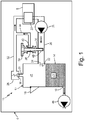
- FIG. 1 is a schematic view of aircraft 6 with engine 8 and shows reservoir assembly 10 with tank 12 (with canister 14, fill port 16, first oil outlet 18, second air outlet 20, inlet 22, and restrictor 24), scavenge pump 25, return passage 26, accessory gearbox 27, pressurization valve 28 (with valve element 30), first passage 32, vent valve 34 (with body 36, channel 38, inlet orifice 40, outlet orifice 42), bleed flow passage 44, air 45, pump 46, and oil 47.
- pressurization valve 28 is shown in a closed position with valve element 30 in a seated position.
- fill port 16 is shown in a closed position.
- reservoir assembly 10 is for use with aircraft 6.
- Tank 12 is a receptacle or storage container for fluid(s).
- tank 12 is an oil reservoir tank.
- Canister 14 is a container such as a hollow tank.
- Fill port 16, first oil outlet 18, second air outlet 20, and inlet 22 are fluidic ports in canister 14.
- Restrictor 24 represents a component which reduces the pressure as the fluid enters tank 12.
- restrictor 24 can be a centrifugal separator.
- restrictor 24 can be a simple orifice.
- Scavenge pump 25 is a fluidic pump.
- scavenge pump 25 is connected to accessory gearbox 27 (or another component from which the air and oil is scavenged).
- Pressurization valve 28 is a fluidic valve.
- pressurization valve 28 is a spring loaded poppet valve.
- Valve element 30 is a movable actuatable flow obstruction.
- Vent valve 34 is a fitting or connector that includes body 36, channel 38, inlet orifice 40, and outlet orifice 42.
- Body 36 is an elongate piece of solid material. In this example, body 36 is a shaft or cylindrical protrusion.
- Channel 38 is a passage.
- Inlet orifice 40 and outlet orifice 42 are fluidic ports.
- Pump 46 is a pump of aircraft 6. In this example, pump 46 can be a lubrication pump.
- Air 45 is air collected from scavenge pump 25.
- Oil 47 is oil or lubricant also collected from scavenge pump 25. In other non-limiting embodiments, air 45 and oil 47 can be collected from other portions of aircraft 6 besides, and/or in addition to, scavenge pump 25.
- Tank 12 is fluidly connected to scavenge pump 25 via return passage 26.
- Tank 12 is fluidly connected to accessory gearbox 27 via first passage 32.
- Canister 14 is connected to return passage 26 via inlet 22.
- Canister 14 is connected to pressurization valve 28 via second air outlet 20.
- Canister 14 is connected to pump 46 via first oil outlet 18.
- Fill port 16 is disposed in a sidewall of canister 14.
- First oil outlet 18 is disposed on a bottom end of canister 14 (with the bottom and a top of canister 14 being a lower end and an upper end, respectively as shown in FIG. 1 ).
- Second air outlet 20 is mounted to a top end of canister 14.
- Inlet 22 is disposed in another sidewall of canister 14.
- Restrictor 24 is mounted to a portion of inlet 22.
- scavenge pump 25 is connected to accessory gearbox 27 (or other component from which the air and oil is scavenged).
- Return passage 26 is connected to and extends between inlet 22 and scavenge pump 25.
- Pressurization valve 28 is connected to second air outlet 20 and to first passage 32.
- Valve element 30 is disposed in pressurization valve 28. In this embodiment, valve element 30 is shown as occupying a seated position within pressurization valve 28.
- First passage 32 is connected to and extends between pressurization valve 28 and accessory gearbox 27.
- Body 36 of vent valve 34 is disposed partially in return passage 26.
- Channel 38 extends between and is fluidly connected to inlet orifice 40 and to outlet orifice 42.
- Channel 38 is disposed through a portion of body 36.
- Inlet orifice 40 is disposed in body 36 and is fluidly connected to channel 38.
- inlet orifice 40 is positioned on a side of body 36 that faces towards tank 12. Put another way, inlet orifice 40 is located on a downstream side of body 36 relative to a direction of flow of air and oil during operation of reservoir assembly 10 (the direction of flow during operation of reservoir assembly 10 is right-to-left as shown in FIG. 1 ).
- Outlet orifice 42 is disposed in body 36 and is fluidly connected to inlet orifice 40 via channel 38.
- Bleed flow passage 44 runs between vent valve 34 and a point along first passage 32. Bleed flow passage 44 fluidly connects outlet orifice 42 to accessory gearbox 27. Pump 46 is fluidly connected to first oil outlet 18 of canister 14. Air 45 is disposed in an upper portion of canister 14 and oil 47 is disposed in a lower portion of canister 14.
- tank 12 collects air and oil scavenged by scavenge pump 25. As air and oil are collected into tank 12, canister 14 contains air 45 and oil 47 within tank 12. Fill port 16 is used to access tank 12 during periods of servicing. Fill port 16 is accessed to add oil to tank 12 after the engine has been shut-down.
- First oil outlet 18 is an orifice that transfers oil out of canister 14 to pump 46.
- Second air outlet 20 transfers air from canister 14 to pressurization valve 28.
- Inlet 22 transfers air and oil from return passage 26 into canister 14.
- restrictor 24 is a centrifugal device that separates air 45 from the oil 47 as an air-oil mixture is delivered to canister 14 by return passage 26. Additionally, during operation of reservoir assembly 10, a pressure differential is created across restrictor 24 such that a pressure in canister 14 is less than a pressure in return passage 26. This pressure differential across restrictor 24 prevents air 45 and oil 47 from being back fed into return passage 26 during operation of reservoir assembly 10. The higher pressure in return passage 26 is created by scavenge pump 25 of the engine that pumps air 45 and oil 47 out of accessory gearbox 27 (or other component from which the air and oil is scavenged).
- scavenge pump 25 scavenges air and oil from accessory gearbox 27.
- Return passage 26 transports air 45 and oil 47 from scavenge pump 25 to inlet 22 of tank 12.
- the height location of return passage 26 being higher relative to a static oil level in tank 12 after shutdown enables air 45 to flow back through restrictor 24 and into return passage 26.
- return passage 26 is located above the static level of oil 47 after shutdown and return passage 26 completely drains into tank 12 so that inlet orifice 40 is exposed to air 45 from tank 12. After shut-down engine 8, the remaining air/oil mixture in return passage 26 drains into tank 12 due to gravity.
- pressurization valve 28 opens to release pressurized air 45 out of tank 12, through second air outlet 20, and into first passage 32.
- Valve element 30 is biased in a closed (or seated) position by a spring element until the pressure inside of tank 12 reaches a threshold value. Once the pressure inside of tank 12 reaches the threshold value, valve element 30 is pushed open (or is un-seated) to allow for an open fluid pathway for air from tank 12 to exit through second air outlet 18 and into return passage 26. When seated, valve element 30 prevents flow of air through pressurization valve 28. In this way, valve element 30 maintains an adequate pressure within tank 12 during operation of reservoir assembly 10 and the engine.
- First passage 32 transports air from pressurization valve 28 back to accessory gearbox 27. First passage 32 also receives air flow from outlet orifice 42 via bleed flow passage 44.
- Vent valve 34 functions to release pressure from tank 12 upon shut-down of engine 8.
- Body 36 provides structural support for vent valve 34 as well as containing channel 38, inlet orifice 40, and outlet orifice 42.
- Channel 38 transports air 45 from inlet orifice 40 to outlet orifice 42 of vent valve 34.
- Inlet orifice 40 receives air 45 from return passage 26, a large portion of which comes from tank 12 after shut-down of the engine.
- inlet orifice 40 is located on a downstream side of body 36 relative to a direction of flow of air and oil through return passage 26 during engine operation. This location of inlet orifice 40 on the downstream side of body 36 causes wake turbulence and flow separation of the air and oil passing by body 36. The wake turbulence and flow separation that the air and oil experiences pushes the air and oil out and around body 36 creating a pocket of low pressure on the downstream side of body 26.
- Outlet orifice 42 delivers air 45 into bleed flow passage 44 from vent valve 34. Bleed flow passage 44 transports air 45 from vent valve 34 back to accessory gearbox 27 of the engine. Pump 46 draws oil 47 from tank 12.
- bleed orifices directly in the canister of the tank are incorporated in order to bleed off tank pressure after shut-down so as to allow removal of the tank cap for servicing.
- a common problem with existing designs however, is that the bleed orifice air flow path is typically large relative to the amount of air (mass flow) returned to the tank under altitude operation.
- the airflow path is parallel to the pressurization valve, it is possible that all of the tank return air can exit the bleed orifice before the tank is pressurized (through the pressurization valve) to the desired level. The result is low tank pressure and diminished lube pump performance.
- vent valve 34 provides a depressurization scheme that does not result in a constant airflow from tank 12 during normal operation. For example, because the bleed orifice in the tank has been eliminated from reservoir assembly 10, tank pressurization is positive under all operating conditions. Instead, the pressure differential across restrictor 24 prevents release of pressure from tank 12 during engine operation until the shut-down phase, during which the pressure differential across restrictor 24 is removed and air 45 can back flow through return passage 26 and into inlet orifice 40. Additionally in this non-limiting embodiment, vent valve 34 does not include any moving parts that can have undesirable failure modes resulting in a reduction of valve reliability.
- FIG. 2 is a schematic view of reservoir assembly 10 and shows tank 12 (with canister 14, fill port 16, first oil outlet 18, second air outlet 20, inlet 22, and restrictor 24), return passage 26, pressurization valve 28 (with valve element 30), first passage 32, vent valve 34 (with body 36, channel 38, inlet orifice 40, outlet orifice 42), bleed flow passage 44, pump 46, air 45, oil 47, and air-oil mix M A/O .
- pressurization valve 28 is shown in an open position with valve element 30 in an unseated position.
- fill port 16 is shown in a closed position.
- reservoir assembly 10 is shown with engine 8 in an operational mode.
- engine 8 With engine 8 being in operation, a positive pressure builds up in canister 14 as air-oil mix M A/O is forced into tank 12 from scavenge pump 25 via return passage 26.
- air 45 and oil 47 are separated either through centrifugal action of a dedicated component, or by natural aspiration of the less dense air from the oil as the mixture resides in the tank.
- valve element 30 of pressurization valve 28 is unseated and pushed into an open position such that air 45 passes through pressurization valve 28 and into first passage 32. Once air 45 enters into first passage 32, air 45 travels through first passage 32 and back to accessory gearbox 27.
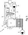
- FIG. 3 is a schematic view of the reservoir assembly 10 and shows tank 12 (with canister 14, fill port 16, first oil outlet 18, second air outlet 20, inlet 22, and restrictor 24), return passage 26, pressurization valve 28 (with valve element 30), first passage 32, vent valve 34 (with body 36, channel 38, inlet orifice 40, outlet orifice 42), bleed flow passage 44, pump 46, air 45, and oil 47.
- pressurization valve 28 is shown in a closed position with valve element 30 in a seated position.
- fill port 16 is shown in an open position.
- reservoir assembly 10 is shown during a shut-down and servicing phase.
- fill port 16 is shown in an open position to allow for a user to access canister 12 for servicing (e.g., to introduce fresh oil 47).
- vent valve 34 In existing reservoir assemblies, without a feature such as vent valve 34, a large positive or negative pressure differential can remain in the reservoir tank upon engine shut-down. Such a scenario can cause difficulty and/or damage to the reservoir tank upon the user attempting to remove the fill port cap with a large pressure differential still present in the tank. In contrast, with vent valve 34 allowing for the depressurization of tank 12 upon shut-down, straight-forward and easy opening of fill port 16 is achieved due to there being little or no pressure differential across fill port 16.
- FIG. 4 is a cross-section view of a portion of reservoir assembly 10 and shows canister 14 and manifold 48 shown in cross-section (with return passage 26, vent valve 34, body 36, channel 38, inlet orifice 40, outlet orifice 42, bleed flow passage 44, pin 50, O-rings 52, and annular opening 54).
- Manifold 48 is a piece of solid material.
- manifold 48 can include a metallic material such as aluminum or steel.
- Pin 50 is a fastener.
- pin 50 can be a rivet, a bolt, or a press-fit pin.
- O-rings 52 are gaskets.
- Annular opening 54 is an annular shaped open area in manifold 48.
- Manifold 48 is attached or mounted to canister 14 of reservoir assembly 10. Pin 50 is inserted through a portion of vent valve 34 and into a receiving orifice of manifold 48.
- O-rings 52 are disposed in various portions of body 36 of vent valve 34.
- O-rings 52 are in sealing contact with body 36 and with manifold 48.
- Annular opening 54 is disposed in manifold 48 such that annular opening 54 encircles a portion of body 36 that outlet orifice 42 opens out of. Annular opening 54 fluidly connects outlet orifice 42 to bleed flow passage 40.
- Manifold 48 provides a support structure for various elements of reservoir assembly 10. For example, bleed flow passage 40 and return passage 26 can be machined out of portions of manifold 48.
- Pin 50 attaches vent valve 34 to manifold 48. In other non-limiting embodiments, a single or multiple of pins 50 can be used to attach canister 14, vent valve 34, and manifold 48 to each other.
- O-rings 52 form a fluidic seal between body 36 of vent valve 34 and a portion of manifold 48 to prevent fluid flow out of manifold 48.
- Annular opening 54 provides a pocket into which bleed air is received from outlet orifice 42 and transferred to bleed flow passage 44.
- An oil reservoir assembly includes a tank, a return passage, a pressurization valve, a first passage, and a vent valve.
- the tank includes a canister, a fill port, an first oil outlet, an second air outlet, and an inlet.
- the inlet is disposed in the canister and is connected to a restrictor.
- the return passage is connected to the inlet of the tank and to a scavenge pump.
- the pressurization valve is fluidly connected to the second air outlet of the tank.
- the first passage is connected to the pressurization valve and to an accessory gearbox of the engine.
- the vent valve is disposed in the return passage and includes a body, a channel extending through the body, an inlet orifice, and an outlet orifice.
- the inlet orifice is disposed in an end of the body.
- the outlet orifice is fluidly connected to the inlet orifice via the channel.
- the assembly of the preceding paragraph can optionally include, additionally and/or alternatively, any one or more of the following features, configurations and/or additional components.
- the outlet orifice can be connected to a bleed flow passage extending from the outlet orifice to a point along the first passage.
- the valve member can comprise a spring loaded poppet valve.
- the first oil outlet can be connected to a pump of the engine.
- the restrictor can comprise a separator configured to separate oil from air.
- the second air outlet of the tank can be in direct fluid communication with the accessory gearbox of the engine.
- the restrictor can comprise a centrifugal separator.
- a method of reducing the pressure in an oil reservoir tank of an aircraft includes turning off an engine of the aircraft.
- a valve element is seated inside of a pressurization valve that is disposed fluidly between a second air outlet of the oil reservoir tank and a first passage connected to an accessory gearbox of the engine. Air and oil are drawn out of the return passage into the oil reservoir tank. A portion of the air is drawn out of the oil reservoir tank through an inlet of the oil reservoir tank and into the return passage. Air is vented from the return passage into a bleed orifice in a vent valve.
- the bleed orifice is disposed in a shaft of the vent valve that extends into the return passage.
- the bleed orifice is connected to a channel extending through the shaft of the vent valve. Air is passed through the channel of the vent valve and into a bleed flow passage connected to the accessory gearbox of the engine.
- the method of the preceding paragraph can optionally include, additionally and/or alternatively, any one or more of the following steps, features, configurations and/or additional components.
- Oil can be removed from the oil reservoir tank through a first oil outlet of the oil reservoir tank.
- a pressure of the oil reservoir tank can be reduced to an ambient pressure.
- the portion of the air can be passed through a restrictor connected to the inlet of the oil reservoir tank.
- the oil reservoir tank can be accessed, after the pressure of the oil reservoir tank has been brought to the ambient pressure, via a fill port of the oil reservoir tank.
Landscapes
- Engineering & Computer Science (AREA)
- General Engineering & Computer Science (AREA)
- Mechanical Engineering (AREA)
- Aviation & Aerospace Engineering (AREA)
- Chemical & Material Sciences (AREA)
- Chemical Kinetics & Catalysis (AREA)
- Lubrication Details And Ventilation Of Internal Combustion Engines (AREA)
Applications Claiming Priority (1)
| Application Number | Priority Date | Filing Date | Title |
|---|---|---|---|
| US16/730,696 US11383854B2 (en) | 2019-12-30 | 2019-12-30 | Oil reservoir vent valve |
Publications (2)
| Publication Number | Publication Date |
|---|---|
| EP3845741A1 true EP3845741A1 (de) | 2021-07-07 |
| EP3845741B1 EP3845741B1 (de) | 2024-03-20 |
Family
ID=72826739
Family Applications (1)
| Application Number | Title | Priority Date | Filing Date |
|---|---|---|---|
| EP20201047.6A Active EP3845741B1 (de) | 2019-12-30 | 2020-10-09 | Ölreservoirentlüftungsventil für ein flugzeugtriebwerk |
Country Status (2)
| Country | Link |
|---|---|
| US (1) | US11383854B2 (de) |
| EP (1) | EP3845741B1 (de) |
Families Citing this family (5)
| Publication number | Priority date | Publication date | Assignee | Title |
|---|---|---|---|---|
| GB201900906D0 (en) * | 2019-01-23 | 2019-03-13 | Rolls Royce Plc | Oil scavenge system |
| US12331879B2 (en) | 2022-06-14 | 2025-06-17 | Pratt & Whitney Canada Corp. | Blowdown valve with air-oil separation |
| US12031463B1 (en) * | 2023-05-31 | 2024-07-09 | Deltahawk Engines, Inc. | Separator for liquid and gas |
| US12352209B1 (en) | 2024-06-25 | 2025-07-08 | Pratt & Whitney Canada Corp. | Aircraft engine fluid separation system and method |
| CN119796504B (zh) * | 2025-01-24 | 2025-12-02 | 中国商用飞机有限责任公司 | 燃油交输装置及辅助动力装置燃油系统 |
Citations (10)
| Publication number | Priority date | Publication date | Assignee | Title |
|---|---|---|---|---|
| US3439497A (en) * | 1966-05-13 | 1969-04-22 | Rolls Royce | Device for protecting a gas turbine engine compressor against the effects of surging |
| EP0143182A1 (de) * | 1983-09-01 | 1985-06-05 | BBC Brown Boveri AG | Abgasturbolader für zweistufige Aufladung eines Verbrennungsmotors mit einer Einrichtung zur Vermeidung von Schmiermittelverlusten |
| EP1333156A1 (de) * | 2002-01-31 | 2003-08-06 | Kabushiki Kaisha Toshiba | Schmierungssystem und Verfahren zur Modifizierung |
| US20050276685A1 (en) * | 2004-06-10 | 2005-12-15 | Wiggins Jimmy D | Pneumatic valve control using downstream pressure feedback and an air turbine starter incorporating the same |
| RU2273745C1 (ru) * | 2004-10-13 | 2006-04-10 | Федеральное государственное унитарное предприятие "Московское машиностроительное производственное предприятие "САЛЮТ" (ФГУП "ММПП "САЛЮТ") | Масляная система газотурбинного двигателя |
| GB2453837A (en) * | 2007-10-19 | 2009-04-22 | Gen Electric | Vent apparatus for filling an oil tank |
| EP2166195A2 (de) * | 2008-09-18 | 2010-03-24 | United Technologies Corporation | Flüssigkeitsbehälter in einer Gasturbine |
| JP2012177341A (ja) * | 2011-02-25 | 2012-09-13 | Mitsubishi Heavy Industries Compressor Corp | オイルコンソール設備 |
| US20140144120A1 (en) * | 2012-11-26 | 2014-05-29 | Hamilton Sundstrand Corporation | Lubrication Cut-Off at High Speed |
| RU2618996C1 (ru) * | 2016-04-06 | 2017-05-11 | Публичное акционерное общество "Уфимское моторостроительное производственное объединение" ПАО УМПО | Маслосистема газотурбинного двигателя |
Family Cites Families (11)
| Publication number | Priority date | Publication date | Assignee | Title |
|---|---|---|---|---|
| DE3137947C2 (de) | 1980-09-26 | 1983-10-27 | Rolls-Royce Ltd., London | Für beliebige Flugmanöver taugliches Schmierölsystem für Gasturbinentriebwerke |
| DE3242366C2 (de) * | 1982-11-16 | 1985-02-07 | MTU Motoren- und Turbinen-Union München GmbH, 8000 München | Ölversorgungseinrichtung für beliebigen Flugsituationen aussetzbare Gasturbinentriebwerke |
| US6463819B1 (en) | 2000-10-24 | 2002-10-15 | Pratt & Whitney Canada Corp. | Uninterruptible oil supply system |
| US8740113B2 (en) * | 2010-02-10 | 2014-06-03 | Tenneco Automotive Operating Company, Inc. | Pressure swirl flow injector with reduced flow variability and return flow |
| DE102010019605A1 (de) * | 2010-05-06 | 2011-11-10 | Rolls-Royce Deutschland Ltd & Co Kg | Fliehkraft-Ölabscheider für ein Flugzeugtriebwerk |
| US9194254B2 (en) | 2012-05-25 | 2015-11-24 | Hamilton Sundstrand Corporation | Reduced velocity valve |
| US9284866B2 (en) | 2012-05-25 | 2016-03-15 | Hamilton Sundstrand Corporation | Valve bypass |
| JP6946244B2 (ja) * | 2018-09-05 | 2021-10-06 | 愛三工業株式会社 | 蒸発燃料処理装置 |
| US11555418B2 (en) * | 2019-06-12 | 2023-01-17 | General Electric Company | Oil supply system for a gas turbine engine |
| US11454571B2 (en) * | 2019-08-21 | 2022-09-27 | Pratt & Whitney Canada Corp. | Sampling tool for lubricating fluid analysis |
| CN110787597B (zh) * | 2019-12-05 | 2024-06-18 | 中国石油大学(北京) | 气液分离设备 |
-
2019
- 2019-12-30 US US16/730,696 patent/US11383854B2/en active Active
-
2020
- 2020-10-09 EP EP20201047.6A patent/EP3845741B1/de active Active
Patent Citations (10)
| Publication number | Priority date | Publication date | Assignee | Title |
|---|---|---|---|---|
| US3439497A (en) * | 1966-05-13 | 1969-04-22 | Rolls Royce | Device for protecting a gas turbine engine compressor against the effects of surging |
| EP0143182A1 (de) * | 1983-09-01 | 1985-06-05 | BBC Brown Boveri AG | Abgasturbolader für zweistufige Aufladung eines Verbrennungsmotors mit einer Einrichtung zur Vermeidung von Schmiermittelverlusten |
| EP1333156A1 (de) * | 2002-01-31 | 2003-08-06 | Kabushiki Kaisha Toshiba | Schmierungssystem und Verfahren zur Modifizierung |
| US20050276685A1 (en) * | 2004-06-10 | 2005-12-15 | Wiggins Jimmy D | Pneumatic valve control using downstream pressure feedback and an air turbine starter incorporating the same |
| RU2273745C1 (ru) * | 2004-10-13 | 2006-04-10 | Федеральное государственное унитарное предприятие "Московское машиностроительное производственное предприятие "САЛЮТ" (ФГУП "ММПП "САЛЮТ") | Масляная система газотурбинного двигателя |
| GB2453837A (en) * | 2007-10-19 | 2009-04-22 | Gen Electric | Vent apparatus for filling an oil tank |
| EP2166195A2 (de) * | 2008-09-18 | 2010-03-24 | United Technologies Corporation | Flüssigkeitsbehälter in einer Gasturbine |
| JP2012177341A (ja) * | 2011-02-25 | 2012-09-13 | Mitsubishi Heavy Industries Compressor Corp | オイルコンソール設備 |
| US20140144120A1 (en) * | 2012-11-26 | 2014-05-29 | Hamilton Sundstrand Corporation | Lubrication Cut-Off at High Speed |
| RU2618996C1 (ru) * | 2016-04-06 | 2017-05-11 | Публичное акционерное общество "Уфимское моторостроительное производственное объединение" ПАО УМПО | Маслосистема газотурбинного двигателя |
Also Published As
| Publication number | Publication date |
|---|---|
| EP3845741B1 (de) | 2024-03-20 |
| US20210197980A1 (en) | 2021-07-01 |
| US11383854B2 (en) | 2022-07-12 |
Similar Documents
| Publication | Publication Date | Title |
|---|---|---|
| EP3845741B1 (de) | Ölreservoirentlüftungsventil für ein flugzeugtriebwerk | |
| US6463819B1 (en) | Uninterruptible oil supply system | |
| US8881764B2 (en) | Offset ambient level fuel feed system | |
| US5046306A (en) | Secondary oil system | |
| US8348017B2 (en) | Reduced gulp fluid reservoir | |
| US10961880B2 (en) | Lubrication circuit, particularly in an aircraft engine | |
| GB1597404A (en) | Auxiliary oil supply systems | |
| US4878923A (en) | Apparatus for removing oil from a compressed gas flow | |
| EP1936201A2 (de) | Verdichtersystem mit Ölabscheider | |
| US2725956A (en) | Aircraft engine lubrication system | |
| JPS6059480B2 (ja) | 潤滑油タンク | |
| US20250290513A1 (en) | Liquid separation device for a compressor system and compressor system having such a liquid separation device | |
| US12442446B2 (en) | Lubrication system with a reserve tank | |
| EP2067514A2 (de) | Kraftstoffsystem und Kraftstofffiltervorrichtung | |
| CA2523195C (en) | Pressure lubrication for inverted flight | |
| EP2666974A2 (de) | Eine Schmiervorrichtung für ein Fluggerät, bestehend aus einem Druckentlastungsventil, eine Ölabscheidungsvorrichtung und einem Öltank, welcher einen Entgaser beinhaltet | |
| US20240376836A1 (en) | Flow draining enhancement system for engine sump cavities | |
| US2755888A (en) | Closed circuit lubrication system | |
| RU2273745C1 (ru) | Масляная система газотурбинного двигателя | |
| EP2666982B1 (de) | Schmiervorrichtung | |
| US12264594B1 (en) | Oil filler tube assembly for aircraft engine | |
| EP4560121A1 (de) | Öleinfüllstutzenanordnung für flugzeugtriebwerk | |
| EP4469669B1 (de) | Ölreservoirpumpenschürze | |
| CA3255426A1 (en) | Oil filler tube assembly for aircraft engine |
Legal Events
| Date | Code | Title | Description |
|---|---|---|---|
| PUAI | Public reference made under article 153(3) epc to a published international application that has entered the european phase |
Free format text: ORIGINAL CODE: 0009012 |
|
| STAA | Information on the status of an ep patent application or granted ep patent |
Free format text: STATUS: THE APPLICATION HAS BEEN PUBLISHED |
|
| AK | Designated contracting states |
Kind code of ref document: A1 Designated state(s): AL AT BE BG CH CY CZ DE DK EE ES FI FR GB GR HR HU IE IS IT LI LT LU LV MC MK MT NL NO PL PT RO RS SE SI SK SM TR |
|
| STAA | Information on the status of an ep patent application or granted ep patent |
Free format text: STATUS: REQUEST FOR EXAMINATION WAS MADE |
|
| 17P | Request for examination filed |
Effective date: 20220105 |
|
| RBV | Designated contracting states (corrected) |
Designated state(s): AL AT BE BG CH CY CZ DE DK EE ES FI FR GB GR HR HU IE IS IT LI LT LU LV MC MK MT NL NO PL PT RO RS SE SI SK SM TR |
|
| STAA | Information on the status of an ep patent application or granted ep patent |
Free format text: STATUS: EXAMINATION IS IN PROGRESS |
|
| 17Q | First examination report despatched |
Effective date: 20230616 |
|
| GRAP | Despatch of communication of intention to grant a patent |
Free format text: ORIGINAL CODE: EPIDOSNIGR1 |
|
| STAA | Information on the status of an ep patent application or granted ep patent |
Free format text: STATUS: GRANT OF PATENT IS INTENDED |
|
| INTG | Intention to grant announced |
Effective date: 20231024 |
|
| GRAS | Grant fee paid |
Free format text: ORIGINAL CODE: EPIDOSNIGR3 |
|
| GRAA | (expected) grant |
Free format text: ORIGINAL CODE: 0009210 |
|
| STAA | Information on the status of an ep patent application or granted ep patent |
Free format text: STATUS: THE PATENT HAS BEEN GRANTED |
|
| AK | Designated contracting states |
Kind code of ref document: B1 Designated state(s): AL AT BE BG CH CY CZ DE DK EE ES FI FR GB GR HR HU IE IS IT LI LT LU LV MC MK MT NL NO PL PT RO RS SE SI SK SM TR |
|
| REG | Reference to a national code |
Ref country code: GB Ref legal event code: FG4D |
|
| REG | Reference to a national code |
Ref country code: CH Ref legal event code: EP |
|
| REG | Reference to a national code |
Ref country code: IE Ref legal event code: FG4D |
|
| REG | Reference to a national code |
Ref country code: DE Ref legal event code: R096 Ref document number: 602020027435 Country of ref document: DE |
|
| PG25 | Lapsed in a contracting state [announced via postgrant information from national office to epo] |
Ref country code: LT Free format text: LAPSE BECAUSE OF FAILURE TO SUBMIT A TRANSLATION OF THE DESCRIPTION OR TO PAY THE FEE WITHIN THE PRESCRIBED TIME-LIMIT Effective date: 20240320 |
|
| REG | Reference to a national code |
Ref country code: LT Ref legal event code: MG9D |
|
| PG25 | Lapsed in a contracting state [announced via postgrant information from national office to epo] |
Ref country code: GR Free format text: LAPSE BECAUSE OF FAILURE TO SUBMIT A TRANSLATION OF THE DESCRIPTION OR TO PAY THE FEE WITHIN THE PRESCRIBED TIME-LIMIT Effective date: 20240621 |
|
| PG25 | Lapsed in a contracting state [announced via postgrant information from national office to epo] |
Ref country code: RS Free format text: LAPSE BECAUSE OF FAILURE TO SUBMIT A TRANSLATION OF THE DESCRIPTION OR TO PAY THE FEE WITHIN THE PRESCRIBED TIME-LIMIT Effective date: 20240620 Ref country code: HR Free format text: LAPSE BECAUSE OF FAILURE TO SUBMIT A TRANSLATION OF THE DESCRIPTION OR TO PAY THE FEE WITHIN THE PRESCRIBED TIME-LIMIT Effective date: 20240320 |
|
| REG | Reference to a national code |
Ref country code: NL Ref legal event code: MP Effective date: 20240320 |
|
| PG25 | Lapsed in a contracting state [announced via postgrant information from national office to epo] |
Ref country code: RS Free format text: LAPSE BECAUSE OF FAILURE TO SUBMIT A TRANSLATION OF THE DESCRIPTION OR TO PAY THE FEE WITHIN THE PRESCRIBED TIME-LIMIT Effective date: 20240620 Ref country code: NO Free format text: LAPSE BECAUSE OF FAILURE TO SUBMIT A TRANSLATION OF THE DESCRIPTION OR TO PAY THE FEE WITHIN THE PRESCRIBED TIME-LIMIT Effective date: 20240620 Ref country code: LT Free format text: LAPSE BECAUSE OF FAILURE TO SUBMIT A TRANSLATION OF THE DESCRIPTION OR TO PAY THE FEE WITHIN THE PRESCRIBED TIME-LIMIT Effective date: 20240320 Ref country code: HR Free format text: LAPSE BECAUSE OF FAILURE TO SUBMIT A TRANSLATION OF THE DESCRIPTION OR TO PAY THE FEE WITHIN THE PRESCRIBED TIME-LIMIT Effective date: 20240320 Ref country code: GR Free format text: LAPSE BECAUSE OF FAILURE TO SUBMIT A TRANSLATION OF THE DESCRIPTION OR TO PAY THE FEE WITHIN THE PRESCRIBED TIME-LIMIT Effective date: 20240621 Ref country code: FI Free format text: LAPSE BECAUSE OF FAILURE TO SUBMIT A TRANSLATION OF THE DESCRIPTION OR TO PAY THE FEE WITHIN THE PRESCRIBED TIME-LIMIT Effective date: 20240320 Ref country code: BG Free format text: LAPSE BECAUSE OF FAILURE TO SUBMIT A TRANSLATION OF THE DESCRIPTION OR TO PAY THE FEE WITHIN THE PRESCRIBED TIME-LIMIT Effective date: 20240320 |
|
| REG | Reference to a national code |
Ref country code: AT Ref legal event code: MK05 Ref document number: 1667993 Country of ref document: AT Kind code of ref document: T Effective date: 20240320 |
|
| PG25 | Lapsed in a contracting state [announced via postgrant information from national office to epo] |
Ref country code: SE Free format text: LAPSE BECAUSE OF FAILURE TO SUBMIT A TRANSLATION OF THE DESCRIPTION OR TO PAY THE FEE WITHIN THE PRESCRIBED TIME-LIMIT Effective date: 20240320 Ref country code: LV Free format text: LAPSE BECAUSE OF FAILURE TO SUBMIT A TRANSLATION OF THE DESCRIPTION OR TO PAY THE FEE WITHIN THE PRESCRIBED TIME-LIMIT Effective date: 20240320 |
|
| PG25 | Lapsed in a contracting state [announced via postgrant information from national office to epo] |
Ref country code: NL Free format text: LAPSE BECAUSE OF FAILURE TO SUBMIT A TRANSLATION OF THE DESCRIPTION OR TO PAY THE FEE WITHIN THE PRESCRIBED TIME-LIMIT Effective date: 20240320 |
|
| PG25 | Lapsed in a contracting state [announced via postgrant information from national office to epo] |
Ref country code: NL Free format text: LAPSE BECAUSE OF FAILURE TO SUBMIT A TRANSLATION OF THE DESCRIPTION OR TO PAY THE FEE WITHIN THE PRESCRIBED TIME-LIMIT Effective date: 20240320 |
|
| PG25 | Lapsed in a contracting state [announced via postgrant information from national office to epo] |
Ref country code: IS Free format text: LAPSE BECAUSE OF FAILURE TO SUBMIT A TRANSLATION OF THE DESCRIPTION OR TO PAY THE FEE WITHIN THE PRESCRIBED TIME-LIMIT Effective date: 20240720 |
|
| PG25 | Lapsed in a contracting state [announced via postgrant information from national office to epo] |
Ref country code: PT Free format text: LAPSE BECAUSE OF FAILURE TO SUBMIT A TRANSLATION OF THE DESCRIPTION OR TO PAY THE FEE WITHIN THE PRESCRIBED TIME-LIMIT Effective date: 20240722 Ref country code: SM Free format text: LAPSE BECAUSE OF FAILURE TO SUBMIT A TRANSLATION OF THE DESCRIPTION OR TO PAY THE FEE WITHIN THE PRESCRIBED TIME-LIMIT Effective date: 20240320 |
|
| PG25 | Lapsed in a contracting state [announced via postgrant information from national office to epo] |
Ref country code: ES Free format text: LAPSE BECAUSE OF FAILURE TO SUBMIT A TRANSLATION OF THE DESCRIPTION OR TO PAY THE FEE WITHIN THE PRESCRIBED TIME-LIMIT Effective date: 20240320 |
|
| PG25 | Lapsed in a contracting state [announced via postgrant information from national office to epo] |
Ref country code: CZ Free format text: LAPSE BECAUSE OF FAILURE TO SUBMIT A TRANSLATION OF THE DESCRIPTION OR TO PAY THE FEE WITHIN THE PRESCRIBED TIME-LIMIT Effective date: 20240320 Ref country code: EE Free format text: LAPSE BECAUSE OF FAILURE TO SUBMIT A TRANSLATION OF THE DESCRIPTION OR TO PAY THE FEE WITHIN THE PRESCRIBED TIME-LIMIT Effective date: 20240320 |
|
| PG25 | Lapsed in a contracting state [announced via postgrant information from national office to epo] |
Ref country code: AT Free format text: LAPSE BECAUSE OF FAILURE TO SUBMIT A TRANSLATION OF THE DESCRIPTION OR TO PAY THE FEE WITHIN THE PRESCRIBED TIME-LIMIT Effective date: 20240320 |
|
| PG25 | Lapsed in a contracting state [announced via postgrant information from national office to epo] |
Ref country code: PL Free format text: LAPSE BECAUSE OF FAILURE TO SUBMIT A TRANSLATION OF THE DESCRIPTION OR TO PAY THE FEE WITHIN THE PRESCRIBED TIME-LIMIT Effective date: 20240320 |
|
| PG25 | Lapsed in a contracting state [announced via postgrant information from national office to epo] |
Ref country code: SK Free format text: LAPSE BECAUSE OF FAILURE TO SUBMIT A TRANSLATION OF THE DESCRIPTION OR TO PAY THE FEE WITHIN THE PRESCRIBED TIME-LIMIT Effective date: 20240320 |
|
| PG25 | Lapsed in a contracting state [announced via postgrant information from national office to epo] |
Ref country code: SM Free format text: LAPSE BECAUSE OF FAILURE TO SUBMIT A TRANSLATION OF THE DESCRIPTION OR TO PAY THE FEE WITHIN THE PRESCRIBED TIME-LIMIT Effective date: 20240320 Ref country code: SK Free format text: LAPSE BECAUSE OF FAILURE TO SUBMIT A TRANSLATION OF THE DESCRIPTION OR TO PAY THE FEE WITHIN THE PRESCRIBED TIME-LIMIT Effective date: 20240320 Ref country code: RO Free format text: LAPSE BECAUSE OF FAILURE TO SUBMIT A TRANSLATION OF THE DESCRIPTION OR TO PAY THE FEE WITHIN THE PRESCRIBED TIME-LIMIT Effective date: 20240320 Ref country code: PT Free format text: LAPSE BECAUSE OF FAILURE TO SUBMIT A TRANSLATION OF THE DESCRIPTION OR TO PAY THE FEE WITHIN THE PRESCRIBED TIME-LIMIT Effective date: 20240722 Ref country code: PL Free format text: LAPSE BECAUSE OF FAILURE TO SUBMIT A TRANSLATION OF THE DESCRIPTION OR TO PAY THE FEE WITHIN THE PRESCRIBED TIME-LIMIT Effective date: 20240320 Ref country code: IS Free format text: LAPSE BECAUSE OF FAILURE TO SUBMIT A TRANSLATION OF THE DESCRIPTION OR TO PAY THE FEE WITHIN THE PRESCRIBED TIME-LIMIT Effective date: 20240720 Ref country code: ES Free format text: LAPSE BECAUSE OF FAILURE TO SUBMIT A TRANSLATION OF THE DESCRIPTION OR TO PAY THE FEE WITHIN THE PRESCRIBED TIME-LIMIT Effective date: 20240320 Ref country code: EE Free format text: LAPSE BECAUSE OF FAILURE TO SUBMIT A TRANSLATION OF THE DESCRIPTION OR TO PAY THE FEE WITHIN THE PRESCRIBED TIME-LIMIT Effective date: 20240320 Ref country code: CZ Free format text: LAPSE BECAUSE OF FAILURE TO SUBMIT A TRANSLATION OF THE DESCRIPTION OR TO PAY THE FEE WITHIN THE PRESCRIBED TIME-LIMIT Effective date: 20240320 Ref country code: AT Free format text: LAPSE BECAUSE OF FAILURE TO SUBMIT A TRANSLATION OF THE DESCRIPTION OR TO PAY THE FEE WITHIN THE PRESCRIBED TIME-LIMIT Effective date: 20240320 |
|
| PG25 | Lapsed in a contracting state [announced via postgrant information from national office to epo] |
Ref country code: IT Free format text: LAPSE BECAUSE OF FAILURE TO SUBMIT A TRANSLATION OF THE DESCRIPTION OR TO PAY THE FEE WITHIN THE PRESCRIBED TIME-LIMIT Effective date: 20240320 |
|
| REG | Reference to a national code |
Ref country code: DE Ref legal event code: R097 Ref document number: 602020027435 Country of ref document: DE |
|
| PG25 | Lapsed in a contracting state [announced via postgrant information from national office to epo] |
Ref country code: IT Free format text: LAPSE BECAUSE OF FAILURE TO SUBMIT A TRANSLATION OF THE DESCRIPTION OR TO PAY THE FEE WITHIN THE PRESCRIBED TIME-LIMIT Effective date: 20240320 |
|
| PG25 | Lapsed in a contracting state [announced via postgrant information from national office to epo] |
Ref country code: DK Free format text: LAPSE BECAUSE OF FAILURE TO SUBMIT A TRANSLATION OF THE DESCRIPTION OR TO PAY THE FEE WITHIN THE PRESCRIBED TIME-LIMIT Effective date: 20240320 |
|
| PLBE | No opposition filed within time limit |
Free format text: ORIGINAL CODE: 0009261 |
|
| STAA | Information on the status of an ep patent application or granted ep patent |
Free format text: STATUS: NO OPPOSITION FILED WITHIN TIME LIMIT |
|
| PG25 | Lapsed in a contracting state [announced via postgrant information from national office to epo] |
Ref country code: DK Free format text: LAPSE BECAUSE OF FAILURE TO SUBMIT A TRANSLATION OF THE DESCRIPTION OR TO PAY THE FEE WITHIN THE PRESCRIBED TIME-LIMIT Effective date: 20240320 |
|
| 26N | No opposition filed |
Effective date: 20241223 |
|
| PG25 | Lapsed in a contracting state [announced via postgrant information from national office to epo] |
Ref country code: SI Free format text: LAPSE BECAUSE OF FAILURE TO SUBMIT A TRANSLATION OF THE DESCRIPTION OR TO PAY THE FEE WITHIN THE PRESCRIBED TIME-LIMIT Effective date: 20240320 |
|
| REG | Reference to a national code |
Ref country code: CH Ref legal event code: PL |
|
| PG25 | Lapsed in a contracting state [announced via postgrant information from national office to epo] |
Ref country code: MC Free format text: LAPSE BECAUSE OF FAILURE TO SUBMIT A TRANSLATION OF THE DESCRIPTION OR TO PAY THE FEE WITHIN THE PRESCRIBED TIME-LIMIT Effective date: 20240320 |
|
| PG25 | Lapsed in a contracting state [announced via postgrant information from national office to epo] |
Ref country code: LU Free format text: LAPSE BECAUSE OF NON-PAYMENT OF DUE FEES Effective date: 20241009 Ref country code: BE Free format text: LAPSE BECAUSE OF NON-PAYMENT OF DUE FEES Effective date: 20241031 |
|
| PG25 | Lapsed in a contracting state [announced via postgrant information from national office to epo] |
Ref country code: CH Free format text: LAPSE BECAUSE OF NON-PAYMENT OF DUE FEES Effective date: 20241031 |
|
| REG | Reference to a national code |
Ref country code: BE Ref legal event code: MM Effective date: 20241031 |
|
| PGFP | Annual fee paid to national office [announced via postgrant information from national office to epo] |
Ref country code: GB Payment date: 20250923 Year of fee payment: 6 |
|
| PGFP | Annual fee paid to national office [announced via postgrant information from national office to epo] |
Ref country code: FR Payment date: 20250924 Year of fee payment: 6 |
|
| PG25 | Lapsed in a contracting state [announced via postgrant information from national office to epo] |
Ref country code: IE Free format text: LAPSE BECAUSE OF NON-PAYMENT OF DUE FEES Effective date: 20241009 |
|
| PGFP | Annual fee paid to national office [announced via postgrant information from national office to epo] |
Ref country code: DE Payment date: 20250923 Year of fee payment: 6 |
|
| PG25 | Lapsed in a contracting state [announced via postgrant information from national office to epo] |
Ref country code: CY Free format text: LAPSE BECAUSE OF FAILURE TO SUBMIT A TRANSLATION OF THE DESCRIPTION OR TO PAY THE FEE WITHIN THE PRESCRIBED TIME-LIMIT; INVALID AB INITIO Effective date: 20201009 |
|
| PG25 | Lapsed in a contracting state [announced via postgrant information from national office to epo] |
Ref country code: HU Free format text: LAPSE BECAUSE OF FAILURE TO SUBMIT A TRANSLATION OF THE DESCRIPTION OR TO PAY THE FEE WITHIN THE PRESCRIBED TIME-LIMIT; INVALID AB INITIO Effective date: 20201009 |