EP3845209B1 - Phaco-emulsifikationshandstück - Google Patents
Phaco-emulsifikationshandstück Download PDFInfo
- Publication number
- EP3845209B1 EP3845209B1 EP21158592.2A EP21158592A EP3845209B1 EP 3845209 B1 EP3845209 B1 EP 3845209B1 EP 21158592 A EP21158592 A EP 21158592A EP 3845209 B1 EP3845209 B1 EP 3845209B1
- Authority
- EP
- European Patent Office
- Prior art keywords
- sonotrode
- housing part
- inner housing
- phacoemulsification handpiece
- handpiece according
- Prior art date
- Legal status (The legal status is an assumption and is not a legal conclusion. Google has not performed a legal analysis and makes no representation as to the accuracy of the status listed.)
- Active
Links
- 239000007788 liquid Substances 0.000 claims description 22
- 238000001816 cooling Methods 0.000 claims description 14
- XEEYBQQBJWHFJM-UHFFFAOYSA-N Iron Chemical compound [Fe] XEEYBQQBJWHFJM-UHFFFAOYSA-N 0.000 claims description 6
- 238000011010 flushing procedure Methods 0.000 claims description 5
- RTAQQCXQSZGOHL-UHFFFAOYSA-N Titanium Chemical compound [Ti] RTAQQCXQSZGOHL-UHFFFAOYSA-N 0.000 claims description 4
- 239000010936 titanium Substances 0.000 claims description 4
- 229910052719 titanium Inorganic materials 0.000 claims description 4
- 229910000831 Steel Inorganic materials 0.000 claims description 3
- 229910052742 iron Inorganic materials 0.000 claims description 3
- 229910052751 metal Inorganic materials 0.000 claims description 3
- 239000002184 metal Substances 0.000 claims description 3
- 239000010959 steel Substances 0.000 claims description 3
- 239000012530 fluid Substances 0.000 claims description 2
- 230000005540 biological transmission Effects 0.000 claims 1
- 230000005284 excitation Effects 0.000 claims 1
- 238000004945 emulsification Methods 0.000 description 25
- 239000000463 material Substances 0.000 description 9
- 229910000838 Al alloy Inorganic materials 0.000 description 6
- 238000004519 manufacturing process Methods 0.000 description 5
- 229910052782 aluminium Inorganic materials 0.000 description 4
- XAGFODPZIPBFFR-UHFFFAOYSA-N aluminium Chemical compound [Al] XAGFODPZIPBFFR-UHFFFAOYSA-N 0.000 description 4
- 239000011248 coating agent Substances 0.000 description 2
- 238000000576 coating method Methods 0.000 description 2
- 239000007769 metal material Substances 0.000 description 2
- 238000002604 ultrasonography Methods 0.000 description 2
- FAPWRFPIFSIZLT-UHFFFAOYSA-M Sodium chloride Chemical compound [Na+].[Cl-] FAPWRFPIFSIZLT-UHFFFAOYSA-M 0.000 description 1
- 238000002399 angioplasty Methods 0.000 description 1
- 238000005452 bending Methods 0.000 description 1
- 239000000560 biocompatible material Substances 0.000 description 1
- 230000001419 dependent effect Effects 0.000 description 1
- 230000000694 effects Effects 0.000 description 1
- 239000000839 emulsion Substances 0.000 description 1
- 238000001727 in vivo Methods 0.000 description 1
- 230000002262 irrigation Effects 0.000 description 1
- 238000003973 irrigation Methods 0.000 description 1
- 230000035515 penetration Effects 0.000 description 1
- 230000002093 peripheral effect Effects 0.000 description 1
- 239000007921 spray Substances 0.000 description 1
- 238000001356 surgical procedure Methods 0.000 description 1
- 231100000732 tissue residue Toxicity 0.000 description 1
- 230000007704 transition Effects 0.000 description 1
Images


Classifications
-
- A—HUMAN NECESSITIES
- A61—MEDICAL OR VETERINARY SCIENCE; HYGIENE
- A61F—FILTERS IMPLANTABLE INTO BLOOD VESSELS; PROSTHESES; DEVICES PROVIDING PATENCY TO, OR PREVENTING COLLAPSING OF, TUBULAR STRUCTURES OF THE BODY, e.g. STENTS; ORTHOPAEDIC, NURSING OR CONTRACEPTIVE DEVICES; FOMENTATION; TREATMENT OR PROTECTION OF EYES OR EARS; BANDAGES, DRESSINGS OR ABSORBENT PADS; FIRST-AID KITS
- A61F9/00—Methods or devices for treatment of the eyes; Devices for putting-in contact lenses; Devices to correct squinting; Apparatus to guide the blind; Protective devices for the eyes, carried on the body or in the hand
- A61F9/007—Methods or devices for eye surgery
- A61F9/00736—Instruments for removal of intra-ocular material or intra-ocular injection, e.g. cataract instruments
- A61F9/00745—Instruments for removal of intra-ocular material or intra-ocular injection, e.g. cataract instruments using mechanical vibrations, e.g. ultrasonic
-
- A—HUMAN NECESSITIES
- A61—MEDICAL OR VETERINARY SCIENCE; HYGIENE
- A61F—FILTERS IMPLANTABLE INTO BLOOD VESSELS; PROSTHESES; DEVICES PROVIDING PATENCY TO, OR PREVENTING COLLAPSING OF, TUBULAR STRUCTURES OF THE BODY, e.g. STENTS; ORTHOPAEDIC, NURSING OR CONTRACEPTIVE DEVICES; FOMENTATION; TREATMENT OR PROTECTION OF EYES OR EARS; BANDAGES, DRESSINGS OR ABSORBENT PADS; FIRST-AID KITS
- A61F9/00—Methods or devices for treatment of the eyes; Devices for putting-in contact lenses; Devices to correct squinting; Apparatus to guide the blind; Protective devices for the eyes, carried on the body or in the hand
- A61F9/0008—Introducing ophthalmic products into the ocular cavity or retaining products therein
-
- A—HUMAN NECESSITIES
- A61—MEDICAL OR VETERINARY SCIENCE; HYGIENE
- A61F—FILTERS IMPLANTABLE INTO BLOOD VESSELS; PROSTHESES; DEVICES PROVIDING PATENCY TO, OR PREVENTING COLLAPSING OF, TUBULAR STRUCTURES OF THE BODY, e.g. STENTS; ORTHOPAEDIC, NURSING OR CONTRACEPTIVE DEVICES; FOMENTATION; TREATMENT OR PROTECTION OF EYES OR EARS; BANDAGES, DRESSINGS OR ABSORBENT PADS; FIRST-AID KITS
- A61F9/00—Methods or devices for treatment of the eyes; Devices for putting-in contact lenses; Devices to correct squinting; Apparatus to guide the blind; Protective devices for the eyes, carried on the body or in the hand
- A61F9/007—Methods or devices for eye surgery
- A61F9/00709—Instruments for removing foreign bodies
-
- A—HUMAN NECESSITIES
- A61—MEDICAL OR VETERINARY SCIENCE; HYGIENE
- A61F—FILTERS IMPLANTABLE INTO BLOOD VESSELS; PROSTHESES; DEVICES PROVIDING PATENCY TO, OR PREVENTING COLLAPSING OF, TUBULAR STRUCTURES OF THE BODY, e.g. STENTS; ORTHOPAEDIC, NURSING OR CONTRACEPTIVE DEVICES; FOMENTATION; TREATMENT OR PROTECTION OF EYES OR EARS; BANDAGES, DRESSINGS OR ABSORBENT PADS; FIRST-AID KITS
- A61F9/00—Methods or devices for treatment of the eyes; Devices for putting-in contact lenses; Devices to correct squinting; Apparatus to guide the blind; Protective devices for the eyes, carried on the body or in the hand
- A61F9/007—Methods or devices for eye surgery
- A61F9/00736—Instruments for removal of intra-ocular material or intra-ocular injection, e.g. cataract instruments
-
- A—HUMAN NECESSITIES
- A61—MEDICAL OR VETERINARY SCIENCE; HYGIENE
- A61B—DIAGNOSIS; SURGERY; IDENTIFICATION
- A61B17/00—Surgical instruments, devices or methods, e.g. tourniquets
- A61B17/22—Implements for squeezing-off ulcers or the like on the inside of inner organs of the body; Implements for scraping-out cavities of body organs, e.g. bones; Calculus removers; Calculus smashing apparatus; Apparatus for removing obstructions in blood vessels, not otherwise provided for
- A61B17/22004—Implements for squeezing-off ulcers or the like on the inside of inner organs of the body; Implements for scraping-out cavities of body organs, e.g. bones; Calculus removers; Calculus smashing apparatus; Apparatus for removing obstructions in blood vessels, not otherwise provided for using mechanical vibrations, e.g. ultrasonic shock waves
-
- A—HUMAN NECESSITIES
- A61—MEDICAL OR VETERINARY SCIENCE; HYGIENE
- A61B—DIAGNOSIS; SURGERY; IDENTIFICATION
- A61B17/00—Surgical instruments, devices or methods, e.g. tourniquets
- A61B2017/00367—Details of actuation of instruments, e.g. relations between pushing buttons, or the like, and activation of the tool, working tip, or the like
- A61B2017/00398—Details of actuation of instruments, e.g. relations between pushing buttons, or the like, and activation of the tool, working tip, or the like using powered actuators, e.g. stepper motors, solenoids
- A61B2017/00402—Piezo electric actuators
-
- A—HUMAN NECESSITIES
- A61—MEDICAL OR VETERINARY SCIENCE; HYGIENE
- A61B—DIAGNOSIS; SURGERY; IDENTIFICATION
- A61B17/00—Surgical instruments, devices or methods, e.g. tourniquets
- A61B17/22—Implements for squeezing-off ulcers or the like on the inside of inner organs of the body; Implements for scraping-out cavities of body organs, e.g. bones; Calculus removers; Calculus smashing apparatus; Apparatus for removing obstructions in blood vessels, not otherwise provided for
- A61B17/22004—Implements for squeezing-off ulcers or the like on the inside of inner organs of the body; Implements for scraping-out cavities of body organs, e.g. bones; Calculus removers; Calculus smashing apparatus; Apparatus for removing obstructions in blood vessels, not otherwise provided for using mechanical vibrations, e.g. ultrasonic shock waves
- A61B17/22012—Implements for squeezing-off ulcers or the like on the inside of inner organs of the body; Implements for scraping-out cavities of body organs, e.g. bones; Calculus removers; Calculus smashing apparatus; Apparatus for removing obstructions in blood vessels, not otherwise provided for using mechanical vibrations, e.g. ultrasonic shock waves in direct contact with, or very close to, the obstruction or concrement
- A61B2017/22014—Implements for squeezing-off ulcers or the like on the inside of inner organs of the body; Implements for scraping-out cavities of body organs, e.g. bones; Calculus removers; Calculus smashing apparatus; Apparatus for removing obstructions in blood vessels, not otherwise provided for using mechanical vibrations, e.g. ultrasonic shock waves in direct contact with, or very close to, the obstruction or concrement the ultrasound transducer being outside patient's body; with an ultrasound transmission member; with a wave guide; with a vibrated guide wire
- A61B2017/22015—Implements for squeezing-off ulcers or the like on the inside of inner organs of the body; Implements for scraping-out cavities of body organs, e.g. bones; Calculus removers; Calculus smashing apparatus; Apparatus for removing obstructions in blood vessels, not otherwise provided for using mechanical vibrations, e.g. ultrasonic shock waves in direct contact with, or very close to, the obstruction or concrement the ultrasound transducer being outside patient's body; with an ultrasound transmission member; with a wave guide; with a vibrated guide wire with details of the transmission member
-
- A—HUMAN NECESSITIES
- A61—MEDICAL OR VETERINARY SCIENCE; HYGIENE
- A61F—FILTERS IMPLANTABLE INTO BLOOD VESSELS; PROSTHESES; DEVICES PROVIDING PATENCY TO, OR PREVENTING COLLAPSING OF, TUBULAR STRUCTURES OF THE BODY, e.g. STENTS; ORTHOPAEDIC, NURSING OR CONTRACEPTIVE DEVICES; FOMENTATION; TREATMENT OR PROTECTION OF EYES OR EARS; BANDAGES, DRESSINGS OR ABSORBENT PADS; FIRST-AID KITS
- A61F2250/00—Special features of prostheses classified in groups A61F2/00 - A61F2/26 or A61F2/82 or A61F9/00 or A61F11/00 or subgroups thereof
- A61F2250/0058—Additional features; Implant or prostheses properties not otherwise provided for
- A61F2250/0093—Ultrasound system, e.g. for inducing coagulation during eye surgery
Definitions
- the invention relates to a phaco-emulsification handpiece, which is primarily a disposable instrument.
- Phaco emulsification handpieces are used as surgical instruments in eye surgery. Examples of such surgical instruments are in WO-A-93/15703-A , WO-A-00/53136-A , EP-A-2 011 458 , DE-A-102 09 495 and DE-C-4 008 594 described.
- WO-A-89/06515 describes a device for in vivo angioplasty having an aluminum alloy horn which may be AI-2024 or AI-7075.
- a phaco emulsification handpiece is used to shatter the lens of the eye and suck off tissue residue.
- the tool is designed as a hollow needle and is set in high-frequency linear back and forth movements by a vibration mechanism of the handpiece, which is designed as an ultrasonic transducer.
- a rinsing liquid for example an emulsion liquid, is fed in around the outside of the hollow needle, which reaches the operating site and is sucked out from there together with dissolved tissue components through the tool and a suction channel of the handpiece.
- phaco emulsification handpiece The costs for manufacturing a phaco emulsification handpiece are not inconsiderable and are essentially determined by the ultrasonic transducer and the housing. Due to the comparatively high production costs, phaco emulsification handpieces are used several times.
- the individual components must be made of comparatively durable materials. If a phaco-emulsification handpiece is to be used multiple times, it must be sterilized after each use or before further use. This is also associated with additional costs and, moreover, is problematic, which is why it has already been considered to develop phaco emulsification handpieces for single use. So far, however, this has failed due to the still very high production costs.
- the object of the invention is therefore to further simplify the individual components of a phaco emulsification handpiece in order to be able to manufacture them more cost-effectively.
- the invention proposes a phaco-emulsification handpiece which is provided with the features of claim 1.
- Individual configurations of the invention are the subject matter of the dependent claims.
- the phaco emulsification handpiece has a housing made of or with plastic. Furthermore, the invention provides that the housing has an inner housing part surrounding at least part of the sonotrode and an outer housing part, between which there is an annular space for the supply and/or for the forwarding of rinsing liquid to the tool.
- the cooling of the sonotrode by the rinsing liquid flowing through the annular space could be problematic in the case of a plastic inner housing part. This depends, for example, on the thickness of the inner housing part from, whereby it should be noted that for reasons of stability, the inner housing part should not be less than a certain thickness.
- the inner housing part of the phaco-emulsification handpiece according to the invention therefore has cooling openings, within which the sonotrode and in particular the middle section of the sonotrode is exposed and comes into contact with rinsing liquid for cooling.
- the problem here is that biocompatibility may no longer exist. It would therefore have to be ensured, for example by means of an appropriate coating, that the aluminum material does not come into contact with the rinsing liquid, at least in those areas of the sonotrode in which it is exposed within the cooling openings.
- the inner housing part has an outlet opening for the front end of the sonotrode and that the outer housing part has an outlet opening which is aligned with the outlet opening of the inner housing part and is spaced from it in the longitudinal extension of the sonotrode, in which the front end of the Sonotrode is arranged and / or over which the front end of the sonotrode protrudes and on which a holding element can be placed, in particular plugged or screwed, from which an elastic sleeve extends, which surrounds the tool from the outside.
- the outer housing part therefore projects beyond the inner housing part at the front end of the phaco-emulsification handpiece.
- the sonotrode protrudes from the inner housing part through the outlet opening of the inner housing part, in particular with its slimmed front end. This front end then extends further through the outer housing part and through its outlet opening, which is designed in particular as a socket, or it ends in this outlet opening.
- the material of the sonotrode should therefore be biocompatible. If an aluminum alloy is used as the material, as proposed according to the invention, and if it turns out that this material is not biocompatible, then the sonotrode would have to be coated with biocompatible material in this area, for example.
- the part of the sonotrode that extends through the annular space in front of the inner housing part can also consist of a metallic material other than aluminum or an aluminum alloy. Then you would have a sonotrode, so to speak, made of different metallic materials.
- Said part of the sonotrode, which is not made of aluminum or an aluminum alloy, can be made, for example, of titanium, iron or steel or another biocompatible metal that withstands the bending waves occurring during operation of the ultrasonic transducer.
- annular space between the inner housing part and the outer housing part at the outlet opening of the inner housing part is adjoined by a further annular space, which is formed by the outer housing part and the front end of the sonotrode and which extends into the through the play between the front end of the sonotrode and the outlet opening of the outer housing part extends defined intermediate space and from there merges into an intermediate space between the tool and the elastic sleeve.
- the ultrasonic transducer is arranged and mounted in the housing of the phaco-emulsification handpiece.
- the sonotrode has two axially spaced receiving grooves, each for a bearing ring, in particular for an elastic bearing ring and preferably for an O-ring, with the two bearing rings bearing against the housing and in particular the inner housing part from the inside for mounting the ultrasonic transducer .
- the sonotrode has a receiving groove for a bearing ring, in particular for an elastic bearing ring and preferably for an O-ring, at its rear end facing away from the front end , Has and that the front end of the sonotrode or the like by inwardly projecting ribs. Projections of a neck of the housing is centered.
- cooling openings are arranged in the area of the housing of the inner housing part lying between the two bearing rings, with the two receiving grooves being formed in the middle section of the sonotrode.
- the bearing rings thus seal the area on both sides of the arrangement of the cooling openings. They are not only used for storage, but also prevent the penetration of rinsing liquid into the inner housing part.
- the housing prefferably has an inlet opening, which opens into the annular space, for the supply of rinsing liquid.
- the housing has, at its rear end remote from the front end of the sonotrode, a passage opening for a suction hose which is connected to the suction channel extending through the sonotrode.
- connection cable that is connected to the piezoceramic element can be led out of the housing.
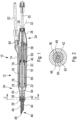
- the Figs. 1 to 4 show different representations of a phaco-emulsification handpiece 10 according to a first embodiment of the invention.
- the handpiece 10 has a housing 12 made of plastic.
- This housing comprises an outer housing part 14 and an inner housing part 16 arranged in the outer housing part 14.
- a first annular space 18 is formed between the two housing parts 14,16, to which the inner housing part 16 is mounted centrally by a plurality of outer projections 20,22.
- At the rear end 24 of the housing 12, this is closed off by a one-part or multi-part cover part 26, from which a suction hose 30 is led out via a through-opening 28.
- a connecting cable 32 is also led out of the cover part 26 .
- the outer housing part 14 projects beyond the inner housing part 16 at the front end 34 of the housing 12.
- a holding element 42 is screwed onto the connecting piece 36, on which there is an elastic sleeve 44 which surrounds a tool 46 in the form of a hollow needle 48 (with a lumen 49) of the handpiece 10.
- Spray liquid enters the annular space 18 of the housing 12 via an inlet opening 50, to which a rinsing liquid hose 52 is connected Sleeve 44 arrives.
- the above-mentioned ultrasonic transducer 40 of the phaco-emulsification handpiece 10 is located in the inner housing part 16 of the housing 12.
- the ultrasonic transducer 40 comprises a sonotrode 56, a resonator 58 and at least one piezoceramic element 60.
- the connecting cable 32 is connected to the piezoceramic element 60.
- a suction channel 62 extends through the sonotrode 56 and is in fluid communication with the lumen of the hollow needle 48 at the front end 64 of the sonotrode 56 and at the rear end 65 of which a connecting piece 66 for connecting the suction tube 30 is provided.
- the sonotrode 56 has a middle section 68, compared to which the front end 64 is slimmed down.
- the rinsing liquid passes through an intermediate space 55 between the connecting piece 36 and the front end 64 of the sonotrode 56 (see FIG 2 ) to which the tool 46 is connected, and further between the tool 46 and the elastic sleeve 44, which expands accordingly when the tool 46 is surrounded by flushing liquid.
- the sonotrode 56 has a likewise slimmed-down rear end piece 70, which extends through the resonator 58, which is designed as a hollow cylinder, and is in threaded engagement with it at 72 stands. In this way, the at least one piezoceramic element 60 can be held clamped between the resonator 58 and the middle section 68 of the sonotrode 56 .
- the middle section 68 of the sonotrode is provided with two peripheral receiving grooves 74 for one elastic bearing ring 76 each, via which the sonotrode 56 and thus the ultrasonic transducer 40 is mounted in the inner housing part 16 of the housing 12 .
- the special feature of the sonotrode 56 described here can be seen in the selection of its material.
- a high-strength aluminum alloy is used, the tensile strength of which is greater than 400 N/mm 2 and in particular greater than 450 N/mm 2 .
- the inner housing part 16 surrounds the middle section 68 of the sonotrode 56 as well as the piezoceramic element 60 and the resonator 58. In the area of the transition from the middle section 68 to the slim front end 64, the sonotrode 56 protrudes from the inner housing part 16.
- the further annular space 54 which is defined by the outer housing part 14 and the slimmed-down front end 64 of the sonotrode 56, adjoins the outlet opening 78 provided on the inner housing part 16.
- the housing 12 is a plastic housing.
- the sonotrode 56 is mounted in the plastic inner housing part 16, via the two bearing rings 76.
- the ultrasonic transducer 40 is pinned to the plastic inner housing part 16 in the area of its sonotrode 56 .
- the sonotrode 56 heats up noticeably, which is why it should be cooled. This is done by the rinsing liquid, for which purpose the plastic inner housing part 16 is provided with several cooling openings 82 in the area around the middle section 68 of the sonotrode 56 (see FIG Figs. 3 and 4 ).
- the central section 68 of the sonotrode 56 is exposed within these cooling openings 82 so that the rinsing liquid can now flow directly along the sonotrode 56 in these areas, whereby the cooling effect is significantly more effective than if the plastic inner housing part 16 were designed to be continuous.
- the rinsing liquid which comes into contact with the tissue to be treated during the operation, flows along the sonotrode 56 in its middle section 68 and in its narrowed end 64 (namely in the annular space 54), care should be taken to ensure that the material of the sonotrode is biocompatible. With an aluminum alloy and a flushing liquid designed as a saline solution, this may not be sufficiently the case.
- the sonotrode 56 should be provided with a biocompatible coating at least in the aforementioned areas.
- the entire front end 64 of the sonotrode 56 can also consist of a biocompatible metal such as titanium. This part of the sonotrode 56 would then be mechanically connected to the remaining part of the sonotrode 56 by screwing, for example.
- the bearing rings 76 are located on both sides of the arrangement of the cooling openings 82 and thus seal the sonotrode 56, in particular with respect to the resonator 58 and the piezoceramic element 60, so that no rinsing liquid can get into this area.
- plastic housing and individual variants thereof are listed in the following feature groups, which can occur in combination with one another or also individually and automatically and in all these cases define the invention and/or refinements of the invention.
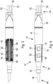
- FIGS Figs. 7 and 8 Based on Figs. 7 and 8 an alternative embodiment of the central mounting of the sonotrode in the housing of the handpiece, which is denoted by 10' in these figures, will be discussed below.
- the individual elements of the handpiece 10 'of Figs. 7 and 8 structurally or functionally those of the handpiece 10 of Figs. 1 to 6 correspond, they are in the Figs. 7 and 8 with the same reference numbers as in FIGS Figs. 1 to 6 marked.
- the difference between the two handpieces 10 and 10' can be seen in the mounting of the sonotrode 56.
- the rear end 65 of the sonotrode 56 is in the handpiece 10' and supported at its central portion by O-ring 76, respectively, while its forward end 64 is centered on inwardly projecting ribs 84 of neck 36 of outer housing member 14 (see Figs 8 ).
- the ribs 84 protrude into the intermediate space 55 and divide it into individual channels 86.
- the ribs 84 also stiffen the connecting piece 36 and thus the housing.
- the front receiving groove 74 of the sonotrode 56 in the handpiece 10 of Figs. 1 to 6 is present can be omitted, which is advantageous in terms of production and assembly (the front O-ring and its assembly on the sonotrode are omitted).
Description
- Die Erfindung betrifft ein Phaco-Emulsifikationshandstück, bei dem es sich vornehmlich um ein Einmal-Instrument handelt.
- Phaco-Emulsifikationshandstücke werden als chirurgische Instrumente in der Augenchirurgie eingesetzt. Beispiele für derartige chirurgische Instrumente sind in
WO-A-93/15703-A WO-A-00/53136-A EP-A-2 011 458 ,DE-A-102 09 495 undDE-C-4 008 594 beschrieben. - In
WO-A-89/06515 - Medizinische Ultraschallvorrichtungen mit Wellenleitern aus verschiedenen Materialien, wie z.B. Titan, Eisen oder Stahl, sind aus
WO-A-2007/070081 bekannt. - Weitere medizinische Ultraschallvorrichtungen sind aus
US-B-7 431 728 bekannt. - Ein Phaco-Emulsifikationshandstück dient zum Zertrümmern der Augenlinse und Absaugen von Geweberesten. Zu diesem Zweck ist das Werkzeug als Hohlnadel ausgebildet und wird von einem Vibrationsmechanismus des Handstücks, der als Ultraschallwandler ausgeführt ist, in Hochfrequente lineare Vor- und Zurückbewegungen versetzt. Außen um die Hohlnadel herum wird eine Spülflüssigkeit, beispielsweise eine Emulsionsflüssigkeit zugeführt, die zur Operationsstelle gelangt und von dort zusammen mit herausgelösten Gewebebestandteilen durch das Werkzeug und einen Absaugkanal des Handstücks abgesaugt wird.
- Die Kosten für die Herstellung eines Phaco-Emulsifikationshandstücks sind nicht unbeträchtlich und werden im Wesentlichen bestimmt durch den Ultraschallwandler und das Gehäuse. Aufgrund der vergleichsweise hohen Herstellungskosten werden daher Phaco-Emulsifikationshandstücke mehrfach verwendet.
- Daher müssen die Einzelkomponenten aus vergleichsweise langlebigen Materialien bestehen. Für den Mehrfacheinsatz eines Phaco-Emulsifikationshandstücks ist dessen Sterilisation nach jedem Gebrauch bzw. vor einem weiteren Gebrauch zwingend erforderlich. Auch dies ist mit zusätzlichen Kosten verbunden und überdies problematisch, weshalb bereits darüber nachgedacht wurde, Phaco-Emulsifikationshandstücke für den Einmalgebrauch zu entwickeln. Dies scheiterte bisher allerdings an den weiterhin recht hohen Herstellungskosten.
- Aus
US-A-2014/271251 ist ein Phaco-Emulsifikationshandstück nach dem Oberbegriff des Anspruchs 1 bekannt. - Ein weiteres bekanntes Phaco-Emulsifikationshandstück ist in
US-A-2014/0276364 beschrieben. Ein weiteres chirurgisches Instrument ist inUS-A-2017/0281216 beschrieben. - Aufgabe der Erfindung ist es daher, die Einzelkomponenten eines Phaco-Emulsifikationshandstücks, weiter zu vereinfachen, um kostengünstiger herstellen zu können.
- Zur Lösung dieser Aufgabe wird mit der Erfindung ein Phaco-Emulsifikationshandstück vorgeschlagen, das versehen ist mit den Merkmalen des Anspruchs 1. Einzelne Ausgestaltungen der Erfindung sind Gegenstand der Unteransprüche.
- Nach der Erfindung weist das Phaco-Emulsifikationshandstück ein Gehäuse aus oder mit Kunststoff auf. Ferner ist erfindungsgemäß vorgesehen, dass das Gehäuse ein zumindest einen Teil der Sonotrode umgebendes Innengehäuseteil und ein Außengehäuseteil aufweist, zwischen denen sich ein Ringraum für die Zuführung und/oder für die Weiterleitung von Spülflüssigkeit zum Werkzeug befindet. Wie bereits oben erwähnt, könnte die Kühlung der Sonotrode durch die durch den Ringraum strömende Spülflüssigkeit bei einem Kunststoff-Innengehäuseteil problematisch sein. Dies hängt beispielsweise von der Dicke des Innengehäuseteils ab, wobei anzumerken ist, dass aus Stabilitätsgründen ein gewisses Dickenmaß für das Innengehäuseteil nicht unterschritten werden sollte. Damit ergibt sich möglicherweise die Schwierigkeit, dass das Innengehäuseteil zu dickwandig ist, um aufgrund seiner Umspülung durch die Spülflüssigkeit die Sonotrode noch ausreichend kühlen zu können. Daher weist das Innengehäuseteil des erfindungsgemäßen Phaco-Emulsifikationshandstücks Kühlöffnungen auf, innerhalb derer die Sonotrode und insbesondere der Mittelabschnitt der Sonotrode freiliegt und zur Kühlung mit Spülflüssigkeit in Kontakt gelangt.
- Würde man nun die Sonotrode aus einem Aluminiumwerkstoff herstellen, wie es mit Vorteil bei dem erfindungsgemäßen Phaco-Emulsifikationshandstück der Fall sein kann, so stellt sich hier das Problem der möglicherweise nicht mehr gegebenen Biokompatibilität. Daher müsste man durch beispielweise eine entsprechende Beschichtung dafür Sorge tragen, dass der Aluminiumwerkstoff zumindest in denjenigen Bereichen der Sonotrode, in denen diese innerhalb der Kühlöffnungen freiliegt, nicht mit Spülflüssigkeit in Kontakt gelangt.
- In weiterer vorteilhafter Ausgestaltung der Erfindung kann vorgesehen sein, dass das Innengehäuseteil eine Austrittsöffnung für das vordere Ende der Sonotrode aufweist und dass das Außengehäuseteil eine mit der Austrittsöffnung des Innengehäuseteils fluchtende und von dieser in Längserstreckung der Sonotrode beabstandete Austrittsöffnung aufweist, in der das vordere Ende der Sonotrode angeordnet ist und/oder über die das vordere Ende der Sonotrode übersteht und auf die ein Halteelement aufsetzbar, insbesondere aufsteck- oder aufschraubbar ist, von dem aus sich eine elastische Hülse erstreckt, die das Werkzeug von außen umgibt. Das Außengehäuseteil steht am vorderen Ende des Phaco-Emulsifikationshandstücks also über das Innengehäuseteil über. Durch die Austrittsöffnung des Innengehäuseteils ragt die Sonotrode aus dem Innengehäuseteil heraus, und zwar insbesondere mit ihrem verschlankten vorderen Ende. Dieses vordere Ende erstreckt sich dann weiter durch das Außengehäuseteil und durch dessen insbesondere als Stutzen ausgebildete Austrittsöffnung bzw. es endet in dieser Austrittsöffnung. Damit schließt sich also an den Ringraum zwischen den beiden Gehäuseteilen ein weiterer Ringraum an, der durch das Außengehäuseteil und die Sonotrode bzw. deren vorderes Ende definiert ist. Auch in diesem Bereich kommt es nun zu einem Kontakt der Spülflüssigkeit mit der Sonotrode. Das Material der Sonotrode sollte also biokompatibel sein. Wenn als Material eine Aluminiumlegierung eingesetzt wird, wie es gemäß der Erfindung vorgeschlagen wird, und wenn es sich herausstellen sollte, dass dieses Material nicht biokompatibel ist, so müsste man also beispielsweise die Sonotrode in diesem Bereich mit biokompatiblem Material beschichten. Alternativ kann selbstverständlich auch der sich durch den dem Innengehäuseteil vorgelagerten Ringraum erstreckende Teil der Sonotrode aus einem anderen metallischen Material als Aluminium bzw. einer Aluminiumlegierung bestehen. Dann hätte man sozusagen eine Sonotrode, die aus verschiedenen metallischen Materialien besteht. Der besagte Teil der Sonotrode, der nicht aus Aluminium bzw. einer Aluminiumlegierung besteht, kann beispielsweise aus Titan, Eisen oder Stahl oder einem anderen biokompatiblen Metall bestehen, das den beim Betrieb des Ultraschallwandlers auftretenden Biegewellen standhält.
- In weiterer zweckmäßiger Ausgestaltung der Erfindung kann vorgesehen sein, dass sich an den Ringraum zwischen dem Innengehäuseteil und dem Außengehäuseteil an der Austrittsöffnung des Innengehäuseteils ein weiterer Ringraum anschließt, der von dem Außengehäuseteil und dem vorderen Ende der Sonotrode gebildet ist und der sich bis in den durch das Spiel zwischen dem vorderen Ende der Sonotrode und der Austrittsöffnung des Außengehäuseteils definierten Zwischenraum erstreckt und von dort in einen Zwischenraum zwischen dem Werkzeug und der elastischen Hülse übergeht.
- Wie bereits oben beschrieben, ist der Ultraschallwandler in dem Gehäuse des Phaco-Emulsifikationshandstücks angeordnet und dort gelagert. Zweckmäßig ist es diesbezüglich, wenn die Sonotrode zwei axial beabstandete Aufnahmenuten für jeweils einen Lagerring, insbesondere für einen elastischen Lagerring und vorzugsweise für einen O-Ring aufweist, wobei die beiden Lagerringe zur Lagerung des Ultraschallwandlers von innen an dem Gehäuse und insbesondere an dem Innengehäuseteil anliegen.
- Alternativ zur zuvor genannten Lagerung und Zentrierung der Sonotrode in dem Gehäuse bzw. in dem Innengehäuseteil kann vorgesehen sein, dass die Sonotrode an ihrem dem vorderen Ende abgewandten hinteren Ende eine Aufnahmenut für einen Lagerring, insbesondere für einen elastischen Lagerring und vorzugsweise für einen O-Ring, aufweist und dass das vordere Ende der Sonotrode durch nach innen vorstehende Rippen o.dgl. Vorsprünge eines Stutzens des Gehäuses zentriert ist.
- Es ist von Vorteil, wenn die Kühlöffnungen in dem zwischen den beiden Lagerringen liegenden Bereich des Gehäuses des Innengehäuseteils angeordnet sind, wobei die beiden Aufnahmenuten in dem Mittelabschnitt der Sonotrode ausgebildet sind. Die Lagerungsringe dichten also den Bereich beidseitig der Anordnung der Kühlöffnungen ab. Sie dienen damit nicht nur der Lagerung, sondern verhindern auch das Eindringen von Spülflüssigkeit in das Innengehäuseteil.
- Zweckmäßig ist es ferner, dass das Gehäuse eine in den Ringraum mündende Einlassöffnung für die Zufuhr von Spülflüssigkeit aufweist.
- Vorn Vorteil kann es sein, wenn das Gehäuse an seinem dem vorderen Ende der Sonotrode abgewandten hinteren Ende eine Durchführöffnung für einen Absaugschlauch aufweist, der mit dem sich durch die Sonotrode hindurch erstreckenden Absaugkanal verbunden ist.
- In weiterer vorteilhafter Ausgestaltung der Erfindung kann aus dem Gehäuse ein Anschlusskabel herausgeführt werden, dass an das Piezokeramikelement angeschlossen ist.
- Die Erfindung wird nachfolgend anhand zweier Ausführungsbeispiele sowie unter Bezugnahme auf die Zeichnung näher erläutert. Im Einzelnen zeigen dabei:
- Fig. 1
- einen Längsschnitt durch ein Phaco-Emulsifikationshandstück,
- Fig. 2
- einen Querschnitt entlang der Linie II-II der
Fig. 1 , - Fig. 3
- eine erste Seitenansicht auf das Phaco-Emulsifikationshandstück gemäß
Fig. 1 mit teilweise aufgebrochenem und im Schnitt dargestelltem Gehäuse, - Fig. 4
- eine weitere Seitenansicht des Phaco-Emulsifikationshandstücks mit ebenfalls teilweise aufgebrochenem, jedoch in Seitenansicht gezeigtem Innengehäuseteil,
- Fig. 5
- eine Seitenansicht des Ultraschallwandlers des Phaco-Emulsifikationshandstück,
- Fig. 6
- einen Längsschnitt durch den Ultraschallwandler gemäß
Fig. 5 , - Fig. 7
- einen Längsschnitt durch ein alternativ ausgebildetes Phaco-Emulsifikationshandstück und
- Fig. 8
- einen Querschnitt entlang der Linie VIII-VIII der
Fig. 7 . - Die
Fign. 1 bis 4 zeigen verschiedene Darstellungen eines Phaco-Emulsifikationshandstück 10 gemäß einem ersten Ausführungsbeispiel der Erfindung. Das Handstück 10 weist ein Gehäuse 12 aus Kunststoff auf. Dieses Gehäuse umfasst einen Außengehäuseteil 14 und einen im Außengehäuseteil 14 angeordneten Innengehäuseteil 16. Zwischen beiden Gehäuseteilen 14,16 bildet sich ein erster Ringraum 18, zu dem das Innengehäuseteil 16 durch mehrere Außenvorsprünge 20, 22 zentrisch gelagert ist. Am hinteren Ende 24 des Gehäuses 12 ist dieses durch ein- oder mehrteiliges Deckelteil 26 abgeschlossen, aus dem über eine Durchführöffnung 28 ein Absaugschlauch 30 herausgeführt ist. Ferner ist aus dem Deckelteil 26 ein Anschlusskabel 32 herausgeführt. Auf diese beiden Komponenten wird später noch eingegangen werden. - Wie anhand der
Fign. 1 bis 4 zu erkennen ist, überragt das Außengehäuseteil 14 an dem vorderen Ende 34 des Gehäuses 12 das Innengehäuseteil 16. Am vorderen Ende 34 des Gehäuses 12 befindet sich ein Stutzen 36, der eine Austrittsöffnung 38 für einen im Gehäuse 12 angeordneten Ultraschallwandler 40 bildet. Auf den Stutzen 36 ist ein Halteelement 42 aufgeschraubt, an dem sich eine elastische Hülse 44 befindet, die ein Werkzeug 46 in Form einer Hohlnadel 48 (mit Lumen 49) des Handstücks 10 umgibt. - Über eine Einlassöffnung 50, an die ein Spülflüssigkeitsschlauch 52 angeschlossen ist, gelangt Sprühflüssigkeit in den Ringraum 18 des Gehäuses 12, die aus dem Ringraum 18 heraus in einen weiteren Ringraum 54 gelangt und von diesem aus der Austrittsöffnung 38 in den Zwischenraum zwischen Werkzeug 46 und elastischer Hülse 44 gelangt.
- Im Innengehäuseteil 16 des Gehäuses 12 befindet sich der bereits oben angesprochene Ultraschallwandler 40 des Phaco-Emulsifikationshandstücks 10.
- Wie anhand der
Fign. 5 und 6 zu erkennen ist, umfasst der Ultraschallwandler 40 eine Sonotrode 56, einen Resonator 58 und mindestens ein Piezokeramikelement 60. An das Piezokeramikelement 60 ist das Anschlusskabel 32 angeschlossen. Durch die Sonotrode 56 hindurch erstreckt sich ein Absaugkanal 62, der an dem vorderen Ende 64 der Sonotrode 56 in Fluidverbindung mit dem Lumen der Hohlnadel 48 steht und an dessen hinterem Ende 65 ein Anschlussstutzen 66 zum Anschluss des Absaugschlauchs 30 vorgesehen ist. Die Sonotrode 56 weist einen Mittelabschnitt 68 auf, gegenüber dem das vordere Ende 64 verschlankt ist. Die Spülflüssigkeit gelangt durch einen Zwischenraum 55 zwischen dem Stutzen 36 und dem vorderen Ende 64 der Sonotrode 56 (sieheFig. 2 ), mit dem das Werkzeug 46 verbunden ist, und weiter zwischen das Werkzeug 46 und die elastische Hülse 44, die sich dementsprechend aufweitet, wenn das Werkzeug 46 von Spülflüssigkeit umgeben ist. - Dem vorderen Ende 64 gegenüberliegend weist die Sonotrode 56 ein ebenfalls verschlanktes hinteres Endstück 70 auf, das sich durch den als Hohlzylinder ausgebildeten Resonator 58 erstreckt und mit diesem bei 72 in Gewindeeingriff steht. Auf diese Weise kann das mindestens eine Piezokeramikelement 60 zwischen Resonator 58 und Mittelabschnitt 68 der Sonotrode 56 eingespannt gehalten werden. Der Mittelabschnitt 68 der Sonotrode ist mit zwei Umfangsaufnahmenuten 74 für jeweils einen elastischen Lagerring 76 versehen, über die die Sonotrode 56 und damit der Ultraschallwandler 40 im Innengehäuseteil 16 des Gehäuses 12 gelagert ist.
- Die Besonderheit der hier beschriebenen Sonotrode 56 ist in der Auswahl ihres Material zu sehen. Erfindungsgemäß wird eine hochfeste Aluminiumlegierung eingesetzt, deren Zugfestigkeit größer als 400 N/mm2 und insbesondere größer als 450 N/mm2 ist.
- Wie anhand von
Fig. 1 zu erkennen ist, umgibt das Innengehäuseteil 16 den Mittelabschnitt 68 der Sonotrode 56 sowie das Piezokeramikelement 60 und den Resonator 58. Im Bereich des Übergangs vom Mittelabschnitt 68 zum verschlankten vorderen Ende 64 ragt die Sonotrode 56 aus dem Innengehäuseteil 16 heraus. An die insoweit am Innengehäuseteil 16 vorgesehene Austrittsöffnung 78 schließt sich der weitere Ringraum 54 an, der definiert ist durch das Außengehäuseteil 14 und das verschlankte vordere Ende 64 der Sonotrode 56. - Wie weiter oben bereits erwähnt, handelt es sich bei dem Gehäuse 12 um ein Gehäuse aus Kunststoff. Die Sonotrode 56 ist in dem Kunststoffinnengehäuseteil 16 gelagert, und zwar über die beiden Lagerringe 76. Bei 80 ist in den
Fign. 3 und6 angedeutet, dass der Ultraschallwandler 40 im Bereich seiner Sonotrode 56 mit dem Kunststoffinnengehäuseteil 16 verstiftelt ist. Beim Betrieb des Ultraschallwandlers 40 erhitzt sich die Sonotrode 56 merklich, weshalb sie gekühlt werden sollte. Dies erfolgt durch die Spülflüssigkeit, wozu das Kunststoff-Innengehäuseteil 16 im Bereich um den Mittelabschnitt 68 der Sonotrode 56 herum mit mehreren Kühlöffnungen 82 versehen ist (sieheFign. 3 und 4 ). Innerhalb dieser Kühlöffnungen 82 liegt die Sonotrode 56 mit ihrem Mittelabschnitt 68 frei, so dass nun die Spülflüssigkeit in diesen Bereichen an der Sonotrode 56 direkt entlangströmen kann, wodurch der Kühleffekt wesentlich effektiver ist als wenn das Kunststoffinnengehäuseteil 16 durchgehend ausgeführt wäre. Dadurch, dass nun die Spülflüssigkeit, die während der Operation mit dem zu behandelnden Gewebe in Kontakt kommt, an der Sonotrode 56 in deren Mittelabschnitt 68 und in deren verschlanktem Ende 64 (nämlich im Ringraum 54) entlangströmt, sollte dafür gesorgt werden, dass das Material der Sonotrode biokompatibel ist. Bei einer Aluminiumlegierung und einer Spülflüssigkeit, die als Kochsalzlösung ausgeführt ist, ist dies möglicherweise nicht in ausreichendem Maße gegeben. Daher sollte die Sonotrode 56 zumindest in den zuvor genannten Bereichen mit einer biokompatiblen Beschichtung versehen sein. Alternativ kann aber auch das gesamte vordere Ende 64 der Sonotrode 56 aus einem biokompatiblen Metall wie beispielsweise Titan bestehen. Dieser Teil der Sonotrode 56 würde dann mit dem restlichen Teil der Sonotrode 56 durch beispielsweise Verschraubung mechanisch verbunden sein. - Wie anhand von
Fig. 3 zu erkennen ist, befinden sich die Lagerringe 76 beidseitig der Anordnung der Kühlöffnungen 82 und dichten somit die Sonotrode 56 insbesondere gegenüber dem Resonator 58 und dem Piezokeramikelement 60 ab, so dass in diesen Bereich keine Spülflüssigkeit gelangen kann. - Die Merkmale des Kunststoffgehäuses und einzelne Varianten davon sind in den nachfolgenden Merkmalsgruppen aufgeführt, die in Kombination miteinander treten können, bzw. auch einzeln selbsttätig und in all diesen Fällen die Erfindung und/oder Ausgestaltungen der Erfindung definieren.
- Anhand der
Fign. 7 und 8 wird nachfolgend auf eine alternative Ausgestaltung der zentrischen Lagerung der Sonotrode im Gehäuse des Handstücks eingegangen, das in diesen Figuren mit 10' bezeichnet ist. Soweit die einzelnen Elemente des Handstücks 10' derFign. 7 und 8 konstruktiv oder funktional denjenigen des Handstücks 10 derFign. 1 bis 6 entsprechen, sind sie in denFign. 7 und 8 mit den gleichen Bezugszeichen wie in denFign. 1 bis 6 gekennzeichnet. - Der Unterschied beider Handstücke 10 und 10' ist in der Lagerung der Sonotrode 56 zu sehen. Im Handstück 10' ist die Sonotrode 56 an ihrem hinteren Ende 65 bzw. in ihrem Mittelabschnitt durch den O-Ring 76 gelagert, während ihr vorderes Ende 64 an nach innen vorstehenden Rippen 84 des Stutzens 36 des Außengehäuseteils 14 zentriert ist (siehe
Fig. 8 ). Die Rippen 84 ragen in den Zwischenraum 55 hinein und unterteilen diesen in Einzelkanäle 86. Die Rippen 84 versteifen zudem den Stutzen 36 und damit das Gehäuse. Die vordere Aufnahmenut 74 der Sonotrode 56, die bei dem Handstück 10 derFign. 1 bis 6 vorhanden ist, kann entfallen, was fertigungs- und montagetechnisch (der vordere O-Ring und dessen Montage an der Sonotrode entfallen) vorteilhaft ist. -
- 10
- (Phaco-Emulsifikations-)Handstück
- 10'
- (Phaco-Emulsifikations-)Handstück
- 12
- Gehäuse
- 14
- Außengehäuseteil
- 16
- Innengehäuseteil
- 18
- Ringraum
- 20
- Außenvorsprünge
- 22
- Außenvorsprünge
- 24
- (hinteres) Ende des Gehäuses
- 26
- Deckelteil
- 28
- Durchführöffnung
- 30
- Absaugschlauch
- 32
- Anschlusskabel
- 34
- (vorderes) Ende des Gehäuses
- 36
- Stutzen
- 38
- Austrittsöffnung für die Sonotrode am Außengehäuseteil
- 40
- Ultraschallwandler
- 42
- Halteelement
- 44
- elastische Hülse (sleeve)
- 46
- Werkzeug
- 48
- Hohlnadel
- 49
- Lumen der Hohlnadel
- 50
- Einlassöffnung
- 52
- Spülflüssigkeitsschlauch
- 54
- Ringraum
- 55
- Zwischenraum zwischen dem Stutzen und dem vorderen Ende der Sonotrode
- 56
- Sonotrode
- 58
- Resonator
- 60
- Piezokeramikelement
- 62
- Absaugkanal
- 64
- vorderes Ende der Sonotrode
- 65
- hinteres Ende der Sonotrode
- 66
- Anschlussstutzen
- 68
- Mittelabschnitt
- 70
- Endstück
- 72
- Gewindeeingriff zwischen Sonotrode und Resonator
- 74
- Umfangsaufnahmenuten
- 76
- Lagerring
- 78
- Austrittsöffnung für die Sonotrode am Innengehäuseteil
- 80
- Verstiftelung
- 82
- Kühlöffnungen
- 84
- (Führungs- und Versteifungs-)Rippen
- 86
- Kanäle
Claims (10)
- Phaco-Emulsifikationshandstück mit- einem Gehäuse (12),- einem Ultraschallwandler (40), der in dem Gehäuse (12) angeordnet ist, und- einem insbesondere Metall wie z.B. Stahl, Eisen oder Titan aufweisenden Werkzeug (46), das zwecks Ultraschallanregung mit dem Ultraschallwandler (40) in Wirkverbindung steht,- wobei der Ultraschallwandler (40) eine Sonotrode (56), einen Resonator (58) und ein zwischen diesen angeordnetes Piezokeramikelement (60) aufweist,- wobei das Gehäuse (12) Kunststoff aufweist und/oder aus Kunststoff besteht, dadurchgekennzeichnet,- dass das Gehäuse (12) ein zumindest einen Teil der Sonotrode (56) umgebendes Innengehäuseteil (16) und ein Außengehäuseteil (14) aufweist, zwischen denen sich ein Ringraum (18) für die Zuführung und/oder für die Weiterleitung von Spülflüssigkeit zum Werkzeug (46) befindet, und- dass das Innengehäuseteil (16) Kühlöffnungen (82) aufweist, innerhalb der die Sonotrode (56) und insbesondere der Mittelabschnitt (68) der Sonotrode (56) freiliegt und zur Kühlung mit Spülflüssigkeit in Kontakt gelangt.
- Phaco-Emulsifikationshandstück nach Anspruch 1, dadurch gekennzeichnet, dass das Innengehäuseteil (16) eine Austrittsöffnung (78) für das vordere Ende (34) der Sonotrode (56) aufweist und dass das Außengehäuseteil (14) eine mit der Austrittsöffnung (38) des Innengehäuseteils (16) fluchtende und von dieser in Längserstreckung der Sonotrode (56) beabstandete Austrittsöffnung (78) aufweist, in der das vordere Ende (34) der Sonotrode (56) angeordnet ist und/oder über die das vordere Ende (34) der Sonotrode (56) übersteht und auf die ein Halteelement (42) aufsetzbar, insbesondere aufsteck- oder aufschraubbar ist, von dem aus sich eine elastische Hülse (44) erstreckt, die das Werkzeug (46) von außen umgibt.
- Phaco-Emulsifikationshandstück nach Anspruch 2, dadurch gekennzeichnet, dass sich an den Ringraum (18) zwischen dem Innengehäuseteil (16) und dem Außengehäuseteil (14) an der Austrittsöffnung (78) des Innengehäuseteils (16) ein weiterer Ringraum (54) anschließt, der von dem Außengehäuseteil (14) und dem vorderen Ende (64) der Sonotrode (56) gebildet ist und der sich bis in den durch ein Spiel zwischen dem vorderen Ende (34) der Sonotrode (56) und der Austrittsöffnung (38) des Außengehäuseteils (14) definierten Zwischenraum (55) erstreckt und von dort in einen Zwischenraum zwischen dem Werkzeug (46) und der elastischen Hülse (44) übergeht.
- Phaco-Emulsifikationshandstück nach einem der Ansprüche 1 bis 3, dadurch gekennzeichnet, dass die Sonotrode (56) zwei axial beabstandete Aufnahmenuten (74) für jeweils einen Lagerring (76), insbesondere für einen elastischen Lagerring und vorzugsweise für einen O-Ring aufweist, wobei die beiden Lagerringe zur Lagerung des Ultraschallwandlers (40) von innen an dem Gehäuse (12) und insbesondere an dem Innengehäuseteil (16) anliegen.
- Phaco-Emulsifikationshandstück nach einem der Ansprüche 1 bis 3, dadurch gekennzeichnet, dass die Sonotrode (56) an ihrem dem vorderen Ende (64) abgewandten hinteren Ende (65) oder in ihrem mittleren Abschnitt eine Aufnahmenut (74) für einen Lagerring (76), insbesondere für einen elastischen Lagerring und vorzugsweise für einen O-Ring, aufweist und dass das vordere Ende (64) der Sonotrode (56) durch nach innen vorstehende Rippen (84) o.dgl. Vorsprünge eines Stutzens (36) des Gehäuses (12) zentriert ist.
- Phaco-Emulsifikationshandstück nach einem der Ansprüche 1 bis 3 oder nach einem der Ansprüche 4 bis 7, sofern auf Anspruch 3 rückbezogen, dadurch gekennzeichnet, dass die Kühlöffnungen (82) in dem zwischen den beiden Lagerringen liegenden Bereich des Gehäuses (12) bzw. des Innengehäuseteils (16) angeordnet sind und dass die beiden Aufnahmenuten (74) in dem Mittelabschnitt (68) der Sonotrode (56) ausgebildet sind.
- Phaco-Emulsifikationshandstück nach einem der Ansprüche 1 bis 6, dadurch gekennzeichnet, dass das Gehäuse (12) eine mit dem Ringraum (18) in Fluidverbindung stehende Einlassöffnung (50) für die Zufuhr von Spülflüssigkeit aufweist.
- Phaco-Emulsifikationshandstück nach einem der Ansprüche 1 bis 7, dadurch gekennzeichnet, dass das Gehäuse (12) an seinem dem vorderen Ende (34) der Sonotrode (56) abgewandten hinteren Ende (24) eine Durchführöffnung (28) für einen Absaugschlauch (30) aufweist, der mit dem sich durch die Sonotrode (56) hindurch erstreckenden Absaugkanal (62) verbunden ist.
- Phaco-Emulsifikationshandstück nach einem der Ansprüche 1 bis 8, dadurch gekennzeichnet, dass aus dem Gehäuse (12) ein Anschlusskabel (32) herausgeführt ist, das an das Piezokeramikelement (60) angeschlossen ist.
- Phaco-Emulsifikationshandstück nach einem der Ansprüche 1 bis 9, dadurch gekennzeichnet, dass das Werkzeug (46) eine Hohlnadel (48) ist.
Applications Claiming Priority (3)
| Application Number | Priority Date | Filing Date | Title |
|---|---|---|---|
| EP2018058600 | 2018-04-04 | ||
| EP19720373.0A EP3773376B1 (de) | 2018-04-04 | 2019-04-03 | Phaco-emulsifikationshandstück |
| PCT/EP2019/058353 WO2019193027A1 (de) | 2018-04-04 | 2019-04-03 | Chirurgisches instrument, insbesondere phaco-emulsifikationshandstück |
Related Parent Applications (2)
| Application Number | Title | Priority Date | Filing Date |
|---|---|---|---|
| EP19720373.0A Division EP3773376B1 (de) | 2018-04-04 | 2019-04-03 | Phaco-emulsifikationshandstück |
| EP19720373.0A Division-Into EP3773376B1 (de) | 2018-04-04 | 2019-04-03 | Phaco-emulsifikationshandstück |
Publications (3)
| Publication Number | Publication Date |
|---|---|
| EP3845209A1 EP3845209A1 (de) | 2021-07-07 |
| EP3845209B1 true EP3845209B1 (de) | 2023-06-07 |
| EP3845209C0 EP3845209C0 (de) | 2023-06-07 |
Family
ID=61972506
Family Applications (2)
| Application Number | Title | Priority Date | Filing Date |
|---|---|---|---|
| EP19720373.0A Active EP3773376B1 (de) | 2018-04-04 | 2019-04-03 | Phaco-emulsifikationshandstück |
| EP21158592.2A Active EP3845209B1 (de) | 2018-04-04 | 2019-04-03 | Phaco-emulsifikationshandstück |
Family Applications Before (1)
| Application Number | Title | Priority Date | Filing Date |
|---|---|---|---|
| EP19720373.0A Active EP3773376B1 (de) | 2018-04-04 | 2019-04-03 | Phaco-emulsifikationshandstück |
Country Status (9)
| Country | Link |
|---|---|
| US (1) | US20210145638A1 (de) |
| EP (2) | EP3773376B1 (de) |
| JP (1) | JP2021520279A (de) |
| KR (1) | KR20210002496A (de) |
| CN (2) | CN111902109B (de) |
| BR (1) | BR112020019314A2 (de) |
| ES (1) | ES2909756T3 (de) |
| RU (1) | RU2020135471A (de) |
| WO (1) | WO2019193027A1 (de) |
Families Citing this family (1)
| Publication number | Priority date | Publication date | Assignee | Title |
|---|---|---|---|---|
| US20230210692A1 (en) * | 2021-12-28 | 2023-07-06 | H. P. Braem Ag | Disposable phaco handpiece |
Citations (1)
| Publication number | Priority date | Publication date | Assignee | Title |
|---|---|---|---|---|
| US20140276364A1 (en) * | 2013-03-15 | 2014-09-18 | Alcon Research, Ltd. | Systems and methods for ocular surgery |
Family Cites Families (22)
| Publication number | Priority date | Publication date | Assignee | Title |
|---|---|---|---|---|
| JPS60236638A (ja) * | 1984-05-11 | 1985-11-25 | 住友ベークライト株式会社 | ハンドピ−ス |
| US4609368A (en) * | 1984-08-22 | 1986-09-02 | Dotson Robert S Jun | Pneumatic ultrasonic surgical handpiece |
| CA1325458C (en) * | 1988-01-22 | 1993-12-21 | Jonathan Bernstein | Vivo ultrasonic system for angioplasty and ultrasonic contrast imaging |
| DE4008594C2 (de) | 1990-03-17 | 1998-06-10 | Geuder Hans Gmbh | Augenchirurgisches Instrument zum Zertrümmern von Linsen und zum Absaugen von Linsentrümmern |
| WO1992010139A1 (en) * | 1990-12-14 | 1992-06-25 | Kelman Charles D | Tissue scraper element for medical use |
| JP3040868B2 (ja) * | 1991-12-26 | 2000-05-15 | 株式会社トーキン | 振動子部品 |
| CA2128730A1 (en) | 1992-02-05 | 1993-08-19 | William F. Whittingham | Improved phacoemulsification handpiece |
| US5453087A (en) * | 1992-07-15 | 1995-09-26 | Malinowski; Igor | Handpiece for cataract surgery |
| DE19700809C2 (de) * | 1997-01-13 | 2003-05-08 | Geuder Ag | Augenchirurgisches Instrument zum Zertrümmern von Augenlinsen mittels Ultraschall und zum Absaugen von Linsentrümmern |
| DE19826912A1 (de) * | 1998-06-17 | 1999-12-23 | Laser & Med Tech Gmbh | Kombiapplikator zur alternierenden und/oder gleichzeitigen Ultraschall- und Laserstrahlungsanwendung zur Phakoemulsifikation |
| US6241700B1 (en) | 1999-03-08 | 2001-06-05 | Alcon Laboratories, Inc. | Surgical handpiece |
| DE10209495C1 (de) | 2002-03-05 | 2003-10-30 | Wefis Vision Gmbh | Chirurgisches Instrument, insbesondere Phaco-Hohlnadel |
| US7431728B2 (en) | 2005-09-06 | 2008-10-07 | Omnisonics Medical Technologies, Inc. | Ultrasound medical devices, systems and methods |
| US8033173B2 (en) | 2005-12-12 | 2011-10-11 | Kimberly-Clark Worldwide, Inc. | Amplifying ultrasonic waveguides |
| EP2011458A1 (de) * | 2007-07-06 | 2009-01-07 | WEFISinnovid GmbH | Chirurgisches Instrument |
| US9044261B2 (en) * | 2007-07-31 | 2015-06-02 | Ethicon Endo-Surgery, Inc. | Temperature controlled ultrasonic surgical instruments |
| US8475480B2 (en) * | 2011-01-04 | 2013-07-02 | Alcon Research Ltd | Multi-sleeved surgical ultrasonic vibrating tool suited for phacoemulsification in a manner that prevents thermal injury to ocular tissue |
| US9750638B2 (en) * | 2013-03-15 | 2017-09-05 | Novartis Ag | Systems and methods for ocular surgery |
| EP2824221A1 (de) * | 2013-07-12 | 2015-01-14 | Eloxal Höfler GmbH | Verfahren zur Herstellung eines korrosionsbeständigen und verschleissfähigen Aluminiumsubstrats |
| DE102013214944A1 (de) * | 2013-07-30 | 2015-02-05 | Söring GmbH | Sonotrode |
| US20160175150A1 (en) * | 2014-12-18 | 2016-06-23 | Surgical Design Corporation | Ultrasonic handpiece with multiple drivers |
| US10342566B2 (en) * | 2016-03-29 | 2019-07-09 | Covidien Lp | Devices, systems, and methods for cooling a surgical instrument |
-
2019
- 2019-04-03 CN CN201980021875.0A patent/CN111902109B/zh active Active
- 2019-04-03 JP JP2021503204A patent/JP2021520279A/ja active Pending
- 2019-04-03 BR BR112020019314-3A patent/BR112020019314A2/pt unknown
- 2019-04-03 ES ES19720373T patent/ES2909756T3/es active Active
- 2019-04-03 EP EP19720373.0A patent/EP3773376B1/de active Active
- 2019-04-03 US US17/044,477 patent/US20210145638A1/en active Pending
- 2019-04-03 KR KR1020207030250A patent/KR20210002496A/ko not_active Application Discontinuation
- 2019-04-03 EP EP21158592.2A patent/EP3845209B1/de active Active
- 2019-04-03 WO PCT/EP2019/058353 patent/WO2019193027A1/de active Application Filing
- 2019-04-03 RU RU2020135471A patent/RU2020135471A/ru unknown
- 2019-04-03 CN CN202310589565.7A patent/CN116672161A/zh active Pending
Patent Citations (1)
| Publication number | Priority date | Publication date | Assignee | Title |
|---|---|---|---|---|
| US20140276364A1 (en) * | 2013-03-15 | 2014-09-18 | Alcon Research, Ltd. | Systems and methods for ocular surgery |
Also Published As
| Publication number | Publication date |
|---|---|
| JP2021520279A (ja) | 2021-08-19 |
| KR20210002496A (ko) | 2021-01-08 |
| EP3845209A1 (de) | 2021-07-07 |
| WO2019193027A1 (de) | 2019-10-10 |
| EP3773376B1 (de) | 2021-12-29 |
| EP3773376A1 (de) | 2021-02-17 |
| CN116672161A (zh) | 2023-09-01 |
| CN111902109A (zh) | 2020-11-06 |
| BR112020019314A2 (pt) | 2021-01-05 |
| US20210145638A1 (en) | 2021-05-20 |
| CN111902109B (zh) | 2023-06-09 |
| ES2909756T3 (es) | 2022-05-10 |
| EP3845209C0 (de) | 2023-06-07 |
| RU2020135471A (ru) | 2022-05-05 |
Similar Documents
| Publication | Publication Date | Title |
|---|---|---|
| EP1325704B1 (de) | Hysteroskop mit Wechselschaftsystem | |
| EP1024760B1 (de) | Medizinisches handstück mit in axialer richtung verschiebbarem lichtleiter | |
| EP2229872B1 (de) | Uretero-Renoskop | |
| DE102005057933B4 (de) | Urologisches Resektoskop mit Isolierkörper am Außenschaft | |
| DE19700809A1 (de) | Augenchirurgisches Instrument zum Zertrümmern von Augenlinsen mittels Ultraschall und zum Absaugen von Linsentrümmern | |
| EP1795217B1 (de) | Absaugkanüle | |
| AT410055B (de) | Laserskalpell | |
| EP3845209B1 (de) | Phaco-emulsifikationshandstück | |
| EP2251142B1 (de) | Einwegdüse | |
| EP2377562B1 (de) | Spülsystem zur Reinigung von Operationswunden | |
| WO2015014650A1 (de) | Sonotrode | |
| EP4278947A1 (de) | Wiederverwendbarer spülschaft für ein endoskop | |
| DE3942905C2 (de) | Endoskop, insbesondere Cystoskop-Urethroskop | |
| WO2015104100A1 (de) | Spülkanüle und verfahren zum herstellen einer spülkanüle | |
| DE10333956A1 (de) | Sichtobturator | |
| EP2011458A1 (de) | Chirurgisches Instrument | |
| DE10033278B4 (de) | Chirurgische Einrichtung zur Entnahme von Gewebezellen aus einer biologischen Struktur | |
| DE102018200971B4 (de) | Hohlnadel für ein augenchirurgisches Instrument und eine die Hohlnadel umgebenden Hülle | |
| DE10246207A1 (de) | Mikrodialysesonde mit spiralförmiger Leitung | |
| EP2293748B1 (de) | Verfahren zur herstellung einer hülle | |
| EP3064158B1 (de) | Medizinische Vorrichtung mit Wasserstrahlapplikator und Verfahren zur Aufrüstung einer chirurgischen Schere | |
| DE202005018532U1 (de) | Operationshandstück für eine Einrichtung zur Entnahme von Gewebezellen | |
| EP3488758A1 (de) | Laryngoskopspatel und verfahren zum herstellen eines laryngoskopspatels | |
| DE3237376A1 (de) | Vorrichtung zum reinigen und sterilisieren eines endoskops | |
| DE202018006303U1 (de) | Schaftinstrument |
Legal Events
| Date | Code | Title | Description |
|---|---|---|---|
| PUAI | Public reference made under article 153(3) epc to a published international application that has entered the european phase |
Free format text: ORIGINAL CODE: 0009012 |
|
| STAA | Information on the status of an ep patent application or granted ep patent |
Free format text: STATUS: THE APPLICATION HAS BEEN PUBLISHED |
|
| AC | Divisional application: reference to earlier application |
Ref document number: 3773376 Country of ref document: EP Kind code of ref document: P |
|
| AK | Designated contracting states |
Kind code of ref document: A1 Designated state(s): AL AT BE BG CH CY CZ DE DK EE ES FI FR GB GR HR HU IE IS IT LI LT LU LV MC MK MT NL NO PL PT RO RS SE SI SK SM TR |
|
| STAA | Information on the status of an ep patent application or granted ep patent |
Free format text: STATUS: REQUEST FOR EXAMINATION WAS MADE |
|
| 17P | Request for examination filed |
Effective date: 20210909 |
|
| RBV | Designated contracting states (corrected) |
Designated state(s): AL AT BE BG CH CY CZ DE DK EE ES FI FR GB GR HR HU IE IS IT LI LT LU LV MC MK MT NL NO PL PT RO RS SE SI SK SM TR |
|
| STAA | Information on the status of an ep patent application or granted ep patent |
Free format text: STATUS: EXAMINATION IS IN PROGRESS |
|
| 17Q | First examination report despatched |
Effective date: 20220512 |
|
| GRAP | Despatch of communication of intention to grant a patent |
Free format text: ORIGINAL CODE: EPIDOSNIGR1 |
|
| STAA | Information on the status of an ep patent application or granted ep patent |
Free format text: STATUS: GRANT OF PATENT IS INTENDED |
|
| INTG | Intention to grant announced |
Effective date: 20221114 |
|
| GRAS | Grant fee paid |
Free format text: ORIGINAL CODE: EPIDOSNIGR3 |
|
| GRAA | (expected) grant |
Free format text: ORIGINAL CODE: 0009210 |
|
| STAA | Information on the status of an ep patent application or granted ep patent |
Free format text: STATUS: THE PATENT HAS BEEN GRANTED |
|
| AC | Divisional application: reference to earlier application |
Ref document number: 3773376 Country of ref document: EP Kind code of ref document: P |
|
| AK | Designated contracting states |
Kind code of ref document: B1 Designated state(s): AL AT BE BG CH CY CZ DE DK EE ES FI FR GB GR HR HU IE IS IT LI LT LU LV MC MK MT NL NO PL PT RO RS SE SI SK SM TR |
|
| REG | Reference to a national code |
Ref country code: GB Ref legal event code: FG4D Free format text: NOT ENGLISH |
|
| REG | Reference to a national code |
Ref country code: CH Ref legal event code: EP Ref country code: AT Ref legal event code: REF Ref document number: 1572639 Country of ref document: AT Kind code of ref document: T Effective date: 20230615 |
|
| REG | Reference to a national code |
Ref country code: DE Ref legal event code: R096 Ref document number: 502019008145 Country of ref document: DE |
|
| U01 | Request for unitary effect filed |
Effective date: 20230706 |
|
| U07 | Unitary effect registered |
Designated state(s): AT BE BG DE DK EE FI FR IT LT LU LV MT NL PT SE SI Effective date: 20230718 |
|
| REG | Reference to a national code |
Ref country code: LT Ref legal event code: MG9D |
|
| PG25 | Lapsed in a contracting state [announced via postgrant information from national office to epo] |
Ref country code: NO Free format text: LAPSE BECAUSE OF FAILURE TO SUBMIT A TRANSLATION OF THE DESCRIPTION OR TO PAY THE FEE WITHIN THE PRESCRIBED TIME-LIMIT Effective date: 20230907 Ref country code: ES Free format text: LAPSE BECAUSE OF FAILURE TO SUBMIT A TRANSLATION OF THE DESCRIPTION OR TO PAY THE FEE WITHIN THE PRESCRIBED TIME-LIMIT Effective date: 20230607 |
|
| PG25 | Lapsed in a contracting state [announced via postgrant information from national office to epo] |
Ref country code: RS Free format text: LAPSE BECAUSE OF FAILURE TO SUBMIT A TRANSLATION OF THE DESCRIPTION OR TO PAY THE FEE WITHIN THE PRESCRIBED TIME-LIMIT Effective date: 20230607 Ref country code: HR Free format text: LAPSE BECAUSE OF FAILURE TO SUBMIT A TRANSLATION OF THE DESCRIPTION OR TO PAY THE FEE WITHIN THE PRESCRIBED TIME-LIMIT Effective date: 20230607 Ref country code: GR Free format text: LAPSE BECAUSE OF FAILURE TO SUBMIT A TRANSLATION OF THE DESCRIPTION OR TO PAY THE FEE WITHIN THE PRESCRIBED TIME-LIMIT Effective date: 20230908 |
|
| PG25 | Lapsed in a contracting state [announced via postgrant information from national office to epo] |
Ref country code: SK Free format text: LAPSE BECAUSE OF FAILURE TO SUBMIT A TRANSLATION OF THE DESCRIPTION OR TO PAY THE FEE WITHIN THE PRESCRIBED TIME-LIMIT Effective date: 20230607 |
|
| PG25 | Lapsed in a contracting state [announced via postgrant information from national office to epo] |
Ref country code: IS Free format text: LAPSE BECAUSE OF FAILURE TO SUBMIT A TRANSLATION OF THE DESCRIPTION OR TO PAY THE FEE WITHIN THE PRESCRIBED TIME-LIMIT Effective date: 20231007 |
|
| PG25 | Lapsed in a contracting state [announced via postgrant information from national office to epo] |
Ref country code: SM Free format text: LAPSE BECAUSE OF FAILURE TO SUBMIT A TRANSLATION OF THE DESCRIPTION OR TO PAY THE FEE WITHIN THE PRESCRIBED TIME-LIMIT Effective date: 20230607 Ref country code: SK Free format text: LAPSE BECAUSE OF FAILURE TO SUBMIT A TRANSLATION OF THE DESCRIPTION OR TO PAY THE FEE WITHIN THE PRESCRIBED TIME-LIMIT Effective date: 20230607 Ref country code: RO Free format text: LAPSE BECAUSE OF FAILURE TO SUBMIT A TRANSLATION OF THE DESCRIPTION OR TO PAY THE FEE WITHIN THE PRESCRIBED TIME-LIMIT Effective date: 20230607 Ref country code: IS Free format text: LAPSE BECAUSE OF FAILURE TO SUBMIT A TRANSLATION OF THE DESCRIPTION OR TO PAY THE FEE WITHIN THE PRESCRIBED TIME-LIMIT Effective date: 20231007 Ref country code: CZ Free format text: LAPSE BECAUSE OF FAILURE TO SUBMIT A TRANSLATION OF THE DESCRIPTION OR TO PAY THE FEE WITHIN THE PRESCRIBED TIME-LIMIT Effective date: 20230607 |
|
| PG25 | Lapsed in a contracting state [announced via postgrant information from national office to epo] |
Ref country code: PL Free format text: LAPSE BECAUSE OF FAILURE TO SUBMIT A TRANSLATION OF THE DESCRIPTION OR TO PAY THE FEE WITHIN THE PRESCRIBED TIME-LIMIT Effective date: 20230607 |
|
| PLBE | No opposition filed within time limit |
Free format text: ORIGINAL CODE: 0009261 |
|
| STAA | Information on the status of an ep patent application or granted ep patent |
Free format text: STATUS: NO OPPOSITION FILED WITHIN TIME LIMIT |