EP3844437B1 - Hervorhebung eines produkts in ladeneinrichtungsstück, -auslage oder -regal - Google Patents
Hervorhebung eines produkts in ladeneinrichtungsstück, -auslage oder -regal Download PDFInfo
- Publication number
- EP3844437B1 EP3844437B1 EP19746090.0A EP19746090A EP3844437B1 EP 3844437 B1 EP3844437 B1 EP 3844437B1 EP 19746090 A EP19746090 A EP 19746090A EP 3844437 B1 EP3844437 B1 EP 3844437B1
- Authority
- EP
- European Patent Office
- Prior art keywords
- product
- lighting device
- segment
- mode
- sensing
- Prior art date
- Legal status (The legal status is an assumption and is not a legal conclusion. Google has not performed a legal analysis and makes no representation as to the accuracy of the status listed.)
- Active
Links
- 230000005291 magnetic effect Effects 0.000 claims description 39
- 238000000034 method Methods 0.000 claims description 10
- 238000005286 illumination Methods 0.000 claims description 8
- 230000008859 change Effects 0.000 claims description 6
- 230000004913 activation Effects 0.000 claims description 4
- 238000004590 computer program Methods 0.000 claims description 3
- 235000014676 Phragmites communis Nutrition 0.000 description 19
- 239000002699 waste material Substances 0.000 description 9
- 238000001514 detection method Methods 0.000 description 6
- 239000003086 colorant Substances 0.000 description 5
- 230000008901 benefit Effects 0.000 description 4
- 230000006870 function Effects 0.000 description 3
- 230000004044 response Effects 0.000 description 3
- 238000010586 diagram Methods 0.000 description 2
- 230000005672 electromagnetic field Effects 0.000 description 2
- 239000002184 metal Substances 0.000 description 2
- 239000008267 milk Substances 0.000 description 2
- 235000013336 milk Nutrition 0.000 description 2
- 210000004080 milk Anatomy 0.000 description 2
- 230000009467 reduction Effects 0.000 description 2
- 238000001228 spectrum Methods 0.000 description 2
- 230000003068 static effect Effects 0.000 description 2
- 230000000007 visual effect Effects 0.000 description 2
- 241000251468 Actinopterygii Species 0.000 description 1
- CWYNVVGOOAEACU-UHFFFAOYSA-N Fe2+ Chemical compound [Fe+2] CWYNVVGOOAEACU-UHFFFAOYSA-N 0.000 description 1
- 244000089486 Phragmites australis subsp australis Species 0.000 description 1
- 230000003796 beauty Effects 0.000 description 1
- 230000004397 blinking Effects 0.000 description 1
- 235000012180 bread and bread product Nutrition 0.000 description 1
- 230000001419 dependent effect Effects 0.000 description 1
- 230000000694 effects Effects 0.000 description 1
- 230000005294 ferromagnetic effect Effects 0.000 description 1
- 235000013332 fish product Nutrition 0.000 description 1
- 230000004907 flux Effects 0.000 description 1
- 239000011521 glass Substances 0.000 description 1
- 239000004615 ingredient Substances 0.000 description 1
- 230000003993 interaction Effects 0.000 description 1
- 238000004519 manufacturing process Methods 0.000 description 1
- 239000003550 marker Substances 0.000 description 1
- 239000000463 material Substances 0.000 description 1
- 239000011159 matrix material Substances 0.000 description 1
- 235000013622 meat product Nutrition 0.000 description 1
- 238000004806 packaging method and process Methods 0.000 description 1
- 238000003825 pressing Methods 0.000 description 1
- 230000001105 regulatory effect Effects 0.000 description 1
- 239000004065 semiconductor Substances 0.000 description 1
- 239000007787 solid Substances 0.000 description 1
- 235000013618 yogurt Nutrition 0.000 description 1
Images


Classifications
-
- F—MECHANICAL ENGINEERING; LIGHTING; HEATING; WEAPONS; BLASTING
- F21—LIGHTING
- F21V—FUNCTIONAL FEATURES OR DETAILS OF LIGHTING DEVICES OR SYSTEMS THEREOF; STRUCTURAL COMBINATIONS OF LIGHTING DEVICES WITH OTHER ARTICLES, NOT OTHERWISE PROVIDED FOR
- F21V23/00—Arrangement of electric circuit elements in or on lighting devices
- F21V23/04—Arrangement of electric circuit elements in or on lighting devices the elements being switches
- F21V23/0442—Arrangement of electric circuit elements in or on lighting devices the elements being switches activated by means of a sensor, e.g. motion or photodetectors
- F21V23/0471—Arrangement of electric circuit elements in or on lighting devices the elements being switches activated by means of a sensor, e.g. motion or photodetectors the sensor detecting the proximity, the presence or the movement of an object or a person
-
- F—MECHANICAL ENGINEERING; LIGHTING; HEATING; WEAPONS; BLASTING
- F21—LIGHTING
- F21V—FUNCTIONAL FEATURES OR DETAILS OF LIGHTING DEVICES OR SYSTEMS THEREOF; STRUCTURAL COMBINATIONS OF LIGHTING DEVICES WITH OTHER ARTICLES, NOT OTHERWISE PROVIDED FOR
- F21V23/00—Arrangement of electric circuit elements in or on lighting devices
- F21V23/04—Arrangement of electric circuit elements in or on lighting devices the elements being switches
-
- A—HUMAN NECESSITIES
- A47—FURNITURE; DOMESTIC ARTICLES OR APPLIANCES; COFFEE MILLS; SPICE MILLS; SUCTION CLEANERS IN GENERAL
- A47F—SPECIAL FURNITURE, FITTINGS, OR ACCESSORIES FOR SHOPS, STOREHOUSES, BARS, RESTAURANTS OR THE LIKE; PAYING COUNTERS
- A47F3/00—Show cases or show cabinets
- A47F3/001—Devices for lighting, humidifying, heating, ventilation
-
- H—ELECTRICITY
- H05—ELECTRIC TECHNIQUES NOT OTHERWISE PROVIDED FOR
- H05B—ELECTRIC HEATING; ELECTRIC LIGHT SOURCES NOT OTHERWISE PROVIDED FOR; CIRCUIT ARRANGEMENTS FOR ELECTRIC LIGHT SOURCES, IN GENERAL
- H05B47/00—Circuit arrangements for operating light sources in general, i.e. where the type of light source is not relevant
- H05B47/10—Controlling the light source
- H05B47/105—Controlling the light source in response to determined parameters
-
- F—MECHANICAL ENGINEERING; LIGHTING; HEATING; WEAPONS; BLASTING
- F21—LIGHTING
- F21W—INDEXING SCHEME ASSOCIATED WITH SUBCLASSES F21K, F21L, F21S and F21V, RELATING TO USES OR APPLICATIONS OF LIGHTING DEVICES OR SYSTEMS
- F21W2131/00—Use or application of lighting devices or systems not provided for in codes F21W2102/00-F21W2121/00
- F21W2131/40—Lighting for industrial, commercial, recreational or military use
- F21W2131/405—Lighting for industrial, commercial, recreational or military use for shop-windows or displays
-
- F—MECHANICAL ENGINEERING; LIGHTING; HEATING; WEAPONS; BLASTING
- F21—LIGHTING
- F21Y—INDEXING SCHEME ASSOCIATED WITH SUBCLASSES F21K, F21L, F21S and F21V, RELATING TO THE FORM OR THE KIND OF THE LIGHT SOURCES OR OF THE COLOUR OF THE LIGHT EMITTED
- F21Y2113/00—Combination of light sources
-
- Y—GENERAL TAGGING OF NEW TECHNOLOGICAL DEVELOPMENTS; GENERAL TAGGING OF CROSS-SECTIONAL TECHNOLOGIES SPANNING OVER SEVERAL SECTIONS OF THE IPC; TECHNICAL SUBJECTS COVERED BY FORMER USPC CROSS-REFERENCE ART COLLECTIONS [XRACs] AND DIGESTS
- Y02—TECHNOLOGIES OR APPLICATIONS FOR MITIGATION OR ADAPTATION AGAINST CLIMATE CHANGE
- Y02B—CLIMATE CHANGE MITIGATION TECHNOLOGIES RELATED TO BUILDINGS, e.g. HOUSING, HOUSE APPLIANCES OR RELATED END-USER APPLICATIONS
- Y02B20/00—Energy efficient lighting technologies, e.g. halogen lamps or gas discharge lamps
- Y02B20/40—Control techniques providing energy savings, e.g. smart controller or presence detection
Definitions
- the invention relates to store lighting.
- the invention relates to a lighting device, a method and a computer program product for highlighting a product in a store fixture, display or shelf.
- Lighting is an important ingredient in the retail store, which can help in creating an atmosphere to encourage shopping and making the interior look interesting and/or appealing.
- lighting used in the retail store is static such that a default predetermined light settings is used for the store.
- Store owners may also use a lighting system that is centrally controlled, for example with control located at a national headquarter instead of at individual store locations.
- US 2015/123547 A1 discloses a lighting system which includes: a light source for lighting display and passage spaces; a first detector for detecting presence or absence of part of a human body in a first detection area; and a second detector for detecting human presence or absence in a second detection area.
- the second detection area contains a whole or part of the passage space.
- the first detection area is nearer to the article than the second detection area.
- a controller controls the light source so that: in a case of detecting human absence, the light source is operated at a reduced light output level; if the second detector detects human presence, illuminance in the display space is increased; and if the first detector detects human presence, illuminance in each of the passage space and the display space is increased.
- US20090189775A1 discloses a highlighting method and an interaction system include at least one controllable light emitting source linked to an item; and a processor configured to turn on the controllable light emitting source in response to user selection of the item.
- the controllable light emitting source may be embedded in a mat or a strip.
- the mat may include a matrix of photo detectors or pressure sensors configured to detect the base or footprint of the item when placed on the mat. The periphery of the product or the footprint may be illuminated upon selecting the product.
- the inventors have realized that a simple way of reducing waste is to attract a shopper's attention, using a lighting system, to products which would benefit from being sold more quickly than others.
- a customer looking to shop in a retail store or in a shop, can be named as a shopper.
- a shopper For example, by selling products that are near their expiry date first, compared to products of the same type that have an expiry date which is further into the future, it can be avoided that products pass their expiry date and are no longer sold but instead need to be discarded off.
- most lighting systems in retail stores merely provide functional background lighting which allows shoppers to see all products as well as, for example, the floor, walls, etc. to help the shopper traverse the retail store in a safe and efficient manner. Such functional background lighting does not allow one product to be highlighted over another product.
- spot lights may be used to provide aesthetically pleasing light for a section of the store. Spot lights can project a bright beam of light onto a store section, to enhance the beauty of, for example, bread, fish or meat products or to make clothing items sparkle. Such lighting is however static and cannot be used to solve the waste reduction problem. Furthermore, adapting such a system to allow the highlighting of one product over another in a manner suitable for causing waste reduction, is difficult and expensive. Using spot lights for highlighting (individual) products in the retail store will be limited with respect to, at least, the number of products that can be highlighted, how close to each other products would have to be positioned, etc. Several spot lights result in an expensive lighting system.
- a lighting device for highlighting a first product over a second product placed in a first and a second section respectively of a store fixture, display or shelf to draw a shopper's attention to the first product.
- the lighting device comprises: a first segment, a second segment and a controller.
- the first segment is arranged for providing a first light output for illuminating the first product.
- the second segment is arranged for providing a second light output for illuminating the second product.
- the first and the second segment are adjacent to each other.
- the controller is arranged for changing an operational mode of the lighting device from a normal lighting mode to a highlighting mode based on a signal indicating presence of a field. In both the normal lighting mode and the highlighting mode, the first segment and the second segment provide illumination. However, in the highlighting mode, the first segment highlights the first product over the second product.
- the lighting device comprises a controller which is arranged for switching the operational mode of the lighting device from the normal lighting mode to the highlighting mode.
- a shopper's attention is drawn towards the first product by highlighting it over the second product.
- Highlighting can make a product stand out amongst other products which otherwise will not receive as much attention from shoppers and can therefore may be left unsold until discarded. Further, with highlighting, the overall appearance of products which are, e.g. old, near to their expiry date, have less attractive packaging, are out of season etc., may be made more appealing and/or attractive.
- a lighting device may comprise more than two segments to allow, when installed in a store fixture, display or shelf, to highlight the first product over the second product by adapting the light emitted towards other products than the first product.
- the light emitted towards the second product may, for example, be dimmed down.
- the controller is arranged for, when the lighting device is operating in the highlighting mode, modifying an intensity and/or modifying a color of the light output of the first segment.
- a product is highlighted by changing the intensity of the first light output compared to the second light output, the product can be made to stand out. Since the product receives, preferably, a higher intensity light, the product becomes more visible to the shopper.
- intensity can be changed with respect to time and can follow a predetermined pattern.
- Another possible way of highlighting is by changing the color of the first light output with respect to the second light output. For example, a white light illuminating the first product compared to a non-white light illuminating the second product can make the first product stand out compared to the second product.
- saturation of the color can be adjusted to perform highlighting.
- the lighting device is comprised in a housing, the housing arranged for attaching the lighting device to the store fixture, display or shelf such that the light emitted by the first segment reflects of at least a shopper facing portion of the first product.
- the shopper facing portion of the first product is in relation to the shopper facing portion of the store display.
- the position of the lighting device in the store display is chosen such that the highlighting of the first product is visible to the shopper.
- the lighting device further comprises a sensing device arranged for sensing the field and to generate the signal indicative of the presence of the field.
- the sensing device is arranged for sensing a magnetic field and further arranged for generating the signal indicative of the presence of the magnetic field.
- the sensing device is magnetically operable switch.
- the housing provides a region to receive a magnetic key card; and the sensing device is arranged for sensing the field when the magnetic key card is provided in the housing.
- the sensing device may further be arranged for sensing at least one or more of the strength of the field, change of the strength of the field in a time period, interval of presence of the field.
- the magnetically operable switch can be a reed contact switch.
- the position of the magnetically operable switch e.g., a reed contact switch may be chosen such that the switch is not visible to the shopper and may be activated by the magnetic key card; wherein only a concerned user e.g., the owner/staff of the retail store, can use the magnetic key card and he knows where the magnetically operable switch, e.g., a reed contact switch is placed.
- the sensing device is a radio-frequency identification, RFID, reader.
- the controller is arranged for changing the operational mode of the lighting device from the normal lighting mode to the highlighting mode when the RFID reader receives a predetermined signal indicative of the presence of an RFID tag.
- the RFID reader is arranged for detecting least one of active tag, passive tag and semi passive tag.
- the controller may be arranged for detecting a predetermined signal indicative of the presence of an RFID tag.
- the RFID reader sends a signal to the tag and reads its response. If the RFID reader detects presence of a predetermined RFID tag (e.g. based on an identifier of the RFID tag), the controller is arranged for switching the operational mode of the lighting device. Only the user e.g., the owner and/or one or more staff of the retail store, will have the access to the RFID tag(s) that can control the lighting device, which prevents the unwanted switching of the lighting device to the highlighting mode.
- the sensing device may be, not according to the invention, a near-field communication (NFC) reader, which allows smart devices such as mobile phone to act as an NFC tag.
- NFC near-field communication
- the user e.g., the owner/staff of the retail store, needs to be in proximity of the NFC reader.
- the lighting device may further comprise an infrared sensor, which causes the lighting device to operate in the unlocked mode while an infrared signal is present (i.e. measured by the infrared sensor), or for a predefined period of time when an infrared signal (e.g. according to a predetermined pattern, signal strength) is measured by the infrared sensor; and to operate the lighting device in the locked mode otherwise.
- an infrared sensor which causes the lighting device to operate in the unlocked mode while an infrared signal is present (i.e. measured by the infrared sensor), or for a predefined period of time when an infrared signal (e.g. according to a predetermined pattern, signal strength) is measured by the infrared sensor; and to operate the lighting device in the locked mode otherwise.
- a store fixture, display or shelf comprising: a first section and a second section for holding a first product and a second product respectively, and a lighting device according to the first aspect.
- a method for highlighting a first product over a second product placed in a first and a second section respectively of a store fixture, display or shelf to draw a shopper's attention to the first product, the method comprising: providing a first light output by a first segment of a lighting device for illuminating the first product, providing a second light output by a second segment of the lighting device, adjacent to the first segment, for illuminating the second product, sensing a field and, based on said sensing, generating a signal indicative of the presence of the field; and changing an operational mode of the lighting device from a normal lighting mode to a highlighting mode based on the signal indicative of the presence of the field; wherein in both the normal lighting mode and the highlighting mode, the first segment and the second segment provide illumination, and wherein in the highlighting mode, the first segment highlights the first product over the second product.
- a computer program product comprising instructions configured to cause a lighting device to execute the steps of the method according to the third aspect.
- Fig. 1 schematically shows the lighting device according to the first aspect.
- the lighting device 100 comprises a first segment 110 and a second segment 120, adjacent to each other.
- the first segment 110 is arranged for providing a first light output 111 and the second segment 120 is arranged for providing a second light output 121.
- the first and the second segment 110, 120 each comprise at least one light source (not shown) and driver circuitry to power the at least one light source (not shown).
- Both segments may comprise an equal number of light sources or alternatively may comprise different number of light sources.
- both segments may comprise the same type of light sources, e.g., LED, fluorescent and incandescent or may comprise different types.
- the lighting device 100 further comprises a controller 130.
- the controller 130 is arranged for changing an operational mode of the lighting device 100 from a normal lighting mode to a highlighting mode based on a signal indicative of the presence of a field.
- the controller 130 is placed adjacent to the first segment 110.
- the controller 130 can be placed elsewhere.
- the controller 130 may, for example, be placed adjacent to the second segment 120 or in between the first segment 110 and the second segment 120.
- the controller 130 may, for example, instead of being physically integrated with the first and second segment of the lighting device 100, be connected remotely to the lighting device 100 (e.g. with a wired/wireless connection).
- the controller 130 may be implemented in a single unit or in the form of a distributed control function distributed amongst the first segment 110 and second segment 120 of the lighting device 100. Furthermore, the controller 130 may be implemented in the form of software stored on a memory and arranged for execution on a processor, or the controller 130 may be implemented in the form of dedicated hardware circuitry, or configurable or reconfigurable circuitry such as a PGA or FPGA, or any combination of these.
- the lighting device 100 further comprises a sensing device 140.
- the sensing device 140 is arranged for sensing the field and to generate the signal indicative of the presence of the field.
- the sensing device 140 is placed in the first segment 110.
- the sensing device 140 can placed elsewhere.
- the sensing device 140 may be placed, for example, in the second segment 120 or in between the first segment 110 and the second segment 120.
- the sensing device 140 may be connected remotely to the lighting device 100 (e.g. with a wired/wireless connection).
- the controller 130 and the sensing device 140 may be combined in a single unit, or the controller may perform the functions of the sensing device.
- Fig. 2 shows an example of a layout of a store fixture, display or shelf 230 using the lighting device 100.
- the store display 230 comprises multiple sections 231, 232, 233, 234, 235, 236 holding multiple products 210, 212, 214, 220,222, 224, respectively.
- the first segment 110 of the lighting device 100 is arranged for providing the first light output 111 for illuminating the first section 231 holding the first product 210 and the second segment 120 of the lighting device 100 is arranged for providing the second light output 121 for illuminating the second section 232 holding the second product 220.
- the lighting device 100 may be placed elsewhere to provide illumination to e.g., sections 233, 234 or sections 235, 236 or any other combination of sections 231, 232, 233, 234, 235, 236.
- the sections 231, 232, 233, 234, 235, 236 of the store display 230 may be physically separated by a separator as shown in Fig. 2 or the sections 231, 232, 233, 234, 235, 236 may not be physically separated by a separator and may be defined in view of the products which each section holds.
- the first product 210 and the second product 220 may belong to the same product type or may belong to different product types.
- both the first product 210 and the second product 220 may be milk cartons in a grocery store or clothing with the same style and/or color in a fashion store.
- the first product 210 may be a yoghurt carton and the second product may be a milk carton in the grocery store or different clothing with different brands, colors and/or designs in the fashion store.
- the lighting device 100 is comprised in a housing 205, wherein the housing 205 is arranged for attaching the lighting device 100 to the store display 230 such that the light emitted by the first segment 110 reflects of at least a shopper facing portion of the first product 210.
- the shopper facing portion of the first product 210 is in relation to the shopper facing portion of the store display 230.
- the lighting device 100 in Fig. 2 , is positioned at the top of the first section 231 and the second section 232 to provide illumination to the first and the second product 210, 220.
- the lighting device 100 may be placed elsewhere, e.g., backside, on the corner etc. as long as the light emitted by the first and second segment of the lighting device 100 reflects, directly or indirectly, of at least shopper facing portions of the first product 210 and the second product 220, respectively.
- the lighting device 100 is arranged for being operable in either the normal lighting mode or in the highlighting mode.
- the first segment 110 and the second segment 120 are arranged for providing the same light output for illuminating the first product 210 and the second product 220.
- the light outputs may have the same intensity as perceived by the shopper at the shopper facing portions of the first product 210 and the second product 220.
- the light outputs may have the same color as perceived by the shopper at the shopper facing portions of the first product 210 and the second product 220.
- the normal lighting mode may be the commonly used default lighting mode of the lighting device 100, wherein the light output settings are predetermined and based e.g., on at least a user and/or shopper preference, product types which are intended to be illuminated, ambience of the store etc.
- the lighting device 100 may be arranged for operating in the normal lighting mode when the lighting device 100 is powered on (e.g. when a power cycle occurs).
- the lighting device 100 comprises the sensing device 140 arranged for sensing the field and to generate the signal indicative of the presence of the field, wherein the controller is arranged for switching the operational mode of the lighting device 100 from the normal lighting mode to the highlighting mode based on the signal indicating the presence of the field.
- the sensing device 140 is arranged for sensing a magnetic field and further arranged for generating a signal indicative of the presence of the magnetic field.
- the sensing device 140 is a magnetically operable switch, e.g., a reed contact switch.
- the reed contact switch is an electrical switch operated by an applied magnetic field. It may consist of a pair of contacts on ferromagnetic metal reeds in a hermetically sealed glass envelope. The contacts may be normally open, closing when a magnetic field is present, or normally closed and opening when a magnetic field is applied.
- the switch may be actuated by a coil, making a reed relay, or by bringing a magnet near to the switch.
- the magnetically operable switch e.g., the reed contact switch
- the magnetically operable switch is arranged for generating a signal indicating the presence of the magnetic field, wherein in an example, the generation of the signal represents the activation of the magnetically operable switch e.g., the reed contact switch, which is activated by applying the magnetic field.
- the sensing device 140 is a radio-frequency identification, RFID, reader, which uses an electromagnetic field to automatically identify RFID tags.
- the RFID tag contains electronically-stored information.
- Two-way radio transmitter-receivers called interrogators or readers send a signal to the tag and read its response; wherein the controller 130 is arranged for changing the operational mode of the lighting device 100 from the normal lighting mode to the highlighting mode when the RFID reader receives a predetermined signal indicating a presence of a RFID tag.
- the controller 130 is arranged for changing the operational mode when the RFID reader receives a signal indicating the presence of a predetermined RFID tag.
- RFID tags can be either active, battery-assisted semi-passive or passive.
- An active tag has an on-board battery, periodically transmits its ID signal and may operate hundreds of meters from the RFID reader.
- a battery-assisted passive (BAP) has a small battery on board and is activated when in the presence of an RFID reader. Passive tags collect energy from a nearby RFID reader's interrogating radio waves.
- the sensing device 140 is a near-field communication (NFC) reader, which can be categorized as a finely-honed version of high frequency RFID.
- NFC near-field communication
- the sensing device 140 is arranged for sensing at least one or more of the presence, the strength of the field sensed by the sensing device 140, the change in strength of the field within a (predetermined) time period, the interval of presence of the field (e.g. the field being present for one second, then not present for two seconds and finally present again for one second).
- the intensity of a magnetic field can be expressed, i.e., magnetic field strength H, measured in amperes per meter (A/m), and magnetic flux density B, measured in Newton-meters per ampere (Nm/A), also called teslas (T).
- the magnetic field strength corresponds to the density of the magnetic field lines.
- the lighting device 100 upon detection of the field, is arranged for switching the operational mode from the normal lighting mode to the highlighting mode.
- the first product 210 is highlighted over the second product 220.
- the first product 210 may be placed in different positions with respect to the second product 220 e.g., the first product 210 may be placed in an upper or lower position with respect to the second product 220 or both products 210, 220 may be placed side-by-side etc.
- the controller 130 is arranged for modifying at least one characteristic of the first light output 111 of the first segment 110 with respect to the second light output 121 of the second segment 120.
- the characteristic of the light output 111 is the intensity of the light output 111.
- the intensity may be modified from one value to at least a different or, preferably, higher value.
- the intensity may be modified dynamically, i.e., intensity values changes over time.
- the change of the intensity may be controlled in an indirect way, e.g., by changing the beam width and/or the beam direction of the light output 111 such that the visual effect perceived by the shopper at the shopper facing portion of the first product 210 is different compared to the visual effect perceived by the shopper at the shopper facing portion of the second product 220.
- the characteristic of the light output 111 is the color of the light output 111.
- the change of color may correspond to the use of contrasting colors, e.g., white versus non-white colors, saturation of colors etc., for the first light output 111 and the second light output 121.
- the color may be modified such that the color changes from one value in the color spectrum to another value in the color spectrum.
- the color may be modified dynamically such that it follows a certain predefined pattern.
- the change of color may correspond to blinking of the light output 111.
- the lighting device 100 may be reset to the normal lighting mode by a power cycle.
- a timer may be used for resetting the lighting device 100 to the normal lighting mode from the highlighting mode or the lighting device is reset to the normal mode in some other way, including based on a further presence of the same or a different field (e.g. the same key card is presented to cause the lighting device to go back to the normal mode).
- the lighting device 100 may be a linear light, e.g., a light strip, or it may be a non-linear light.
- the lighting device 100 is a Refrigerated Display case Lighting (RDL) used in retail stores.
- the sensing device 140 e.g., reed contact switch
- the sensing device 140 is positioned such that it prevents influencing the light disturbance of the RDL module. In this way, when the module is supplied with the power to provide illumination, the sensing device 140, e.g. the reed contact switch and the corresponding electronic circuit (not shown), is hardly visible.
- RDL modules are typically powered by a constant voltage power supply of 24V. This voltage is used to power the corresponding electronic circuit, e.g., electronic reed contact circuit.
- the bracket of the Refrigerated Display Lighting (RDL) is from a non-ferrous metal.
- Fig. 3 shows an example implementation of the lighting device 100 as an LED tube, TLED, 300.
- a LED Light Emitting Diode
- the LED may be controlled conveniently, and the light intensity and/or color of light may be regulated at will only by adjusting a current.
- LEDs have different light color configurations, and various light color effects may be achieved by adjusting light intensities of LEDs with different light colors. LEDs have been widely applied to various types of lighting devices, such as a battery-powered flashlight, a mini-sized sound control lamp, a safety flare, illuminating lamps for roadways and indoor stairs, and building and marker continuous lighting lamps.
- the lighting device 300 comprises two end caps 302 and a sensing device 340.
- the sensing device 340 is may magnetically operable switch, e.g., the reed contact switch.
- a key card 350 is arranged for generating a field 351.
- the housing of the lighting device 300 provides a region to receive the key card 350; and the sensing device 340 is arranged for sensing the field 351 when the key card 350 is provided in the housing of the lighting device 300.
- the key card 350 is received and it is e.g.
- the sensing device 340 is a magnetically operable switch, e.g., the reed contact switch
- the key card 350 is arranged for generating a magnetic field 351 and the generation of the signal indicative of the presence of the magnetic field 351 corresponds to the activation of the magnetically operable switch, e.g., the reed contact switch.
- the magnetically operable switch e.g. the reed contact switch
- unwanted switching e.g. a shopper intentionally or accidently switching the operational mode
- the magnetically operable switch can be mounted inside the lighting device 300 in such a way that the magnetically operable switch, e.g. the reed contact switch, is not visible and can only be activated with a magnetic key card 350.
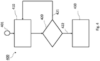
- Fig. 4 shows a flow diagram of the method for highlighting the first product 210 over the second product 220, respectively, placed in a first section 231 and the second section 232 of the store display 230 to draw a shopper's attention to the first product 231.
- Step 401 shows the start of the flow diagram.
- step 410 the first segment 110 and the second segment 120 are arranged for providing the first light output 111 and the second light output 121 for illuminating the first product 210 and the second product 220 respectively.
- the sensing device 140 is arranged for sensing the field.
- the sensing device 140 is a magnetically operable switch, e.g., the reed contact switch which is arranged for sensing the magnetic field and further arranged for generating the signal indicative of the presence of the field.
- the sensing device 140 is a radio-frequency identification, RFID, reader, which uses an electromagnetic field to automatically identify RFID tags.
- the sensing device 140 may be a near-field communication (NFC) reader.
- NFC near-field communication
- step 430 the controller 130 is arranged for changing the operational mode of the lighting device 100 from the normal lighting mode to the highlighting mode based on the signal indicating the presence of the field; wherein in both the normal lighting mode and the highlighting mode, the first segment 110 and the second segment 120 provide illumination, and wherein in the highlighting mode, the first segment 110 highlights the first product 210 over the second product 220.
Landscapes
- Engineering & Computer Science (AREA)
- General Engineering & Computer Science (AREA)
- Circuit Arrangement For Electric Light Sources In General (AREA)
Claims (7)
- Beleuchtungsvorrichtung (100) zum Hervorheben eines ersten Produkts (210) im Vergleich zu einem zweiten Produkt (220), die in einem ersten bzw. in einem zweiten Abschnitt (231, 232) eines/einer Ladeneinrichtungsstücks, -auslage oder -regals (230) platziert sind, um die Aufmerksamkeit eines Käufers auf das erste Produkt (210) zu lenken, die Beleuchtungsvorrichtung umfassend:- ein erstes Segment (110), das zum Bereitstellen einer ersten Lichtausgabe (111) zum Beleuchten des ersten Produkts (210) eingerichtet ist,- ein zweites Segment (120), angrenzend an das erste Segment (110), das zum Bereitstellen einer zweiten Lichtausgabe (121) zum Beleuchten des zweiten Produkts (210) eingerichtet ist,
wobei die Beleuchtungsvorrichtung in einem Gehäuse (205) enthalten ist, wobei das Gehäuse (205) zum Befestigen der Beleuchtungsvorrichtung an dem/der Ladeneinrichtungsstück, -auslage oder -regal (230) eingerichtet ist, sodass das durch das erste Segment (110) abgegebene Licht an mindestens einem einem Käufer zugewandten Abschnitt des ersten Produkts (210) reflektiert wird,- eine Erfassungsvorrichtung (140), die zum Erfassen eines Magnetfelds und zum Erzeugen eines Signals, das das Vorhandensein des Magnetfelds angibt, eingerichtet ist, wobei die Erfassungsvorrichtung (140) ein magnetisch betreibbarer Schalter ist, und
wobei das Gehäuse (205) einen Bereich zum Aufnehmen einer Magnetschlüsselkarte bereitstellt; und die Erfassungsvorrichtung zum Erfassen des Magnetfelds, wenn die Magnetschlüsselkarte in dem Gehäuse bereitgestellt ist, eingerichtet ist und die Erzeugung des Signals, durch die Magnetschlüsselkarte, das das Vorhandensein des Magnetfelds angibt, der Betätigung des magnetisch betreibbaren Schalters entspricht;- eine Steuereinheit (130), die zum Ändern eines Betriebsmodus der Beleuchtungsvorrichtung von einem normalen Beleuchtungsmodus in einen Hervorhebungsmodus auf der Grundlage des Signals, das das Vorhandensein des Magnetfelds angibt, eingerichtet ist;
wobei sowohl in dem normalen Beleuchtungsmodus als auch in dem Hervorhebungsmodus das erste Segment (110) und das zweite Segment (120) eine Beleuchtung bereitstellen und wobei in dem Hervorhebungsmodus das erste Segment (110) das erste Produkt (210) im Vergleich zu dem zweiten Produkt (220) hervorhebt. - Beleuchtungsvorrichtung nach Anspruch 1, wobei die Steuereinheit zum Modifizieren einer Intensität der Lichtausgabe des ersten Segments, wenn die Beleuchtungsvorrichtung in dem Hervorhebungsmodus arbeitet, eingerichtet ist.
- Beleuchtungsvorrichtung nach Anspruch 1, wobei die Steuereinheit zum Modifizieren einer Farbe der Lichtausgabe des ersten Segments, wenn die Beleuchtungsvorrichtung in dem Hervorhebungsmodus arbeitet, eingerichtet ist.
- Beleuchtungsvorrichtung nach Anspruch 1, wobei die Erfassungsvorrichtung zum Erfassen von mindestens einem oder mehreren von der Stärke des Felds, der Änderung der Stärke des Felds in einem Zeitraum, des Intervalls des Vorhandenseins des Felds eingerichtet ist.
- Ladeneinrichtungsstück, -auslage oder -regal, umfassend:- einen ersten Abschnitt und einen zweiten Abschnitt zum Halten eines ersten Produkts bzw. eines zweiten Produkts; und- eine Beleuchtungsvorrichtung nach Anspruch 1.
- Verfahren zum Hervorheben eines ersten Produkts im Vergleich zu einem zweiten Produkt, das in einem ersten bzw. einem zweiten Abschnitt eines/er Lagereinrichtungsstücks, -auslage oder -regals platziert ist, um die Aufmerksamkeit eines Käufers auf das erste Produkt zu lenken, das Verfahren umfassend:- Bereitstellen einer ersten Lichtausgabe durch ein erstes Segment einer Beleuchtungsvorrichtung zum Beleuchten des ersten Produkts,- Bereitstellen einer zweiten Lichtausgabe durch ein zweites Segment der Beleuchtungsvorrichtung, angrenzend an das erste Segment, zum Beleuchten des zweiten Produkts, wobei die Beleuchtungsvorrichtung in einem Gehäuse enthalten ist, wobei das Gehäuse zum Befestigen der Beleuchtungsvorrichtung an dem/der Ladeneinrichtungsstück, -auslage oder -regal eingerichtet ist, sodass das durch das erste Segment abgegebene Licht an mindestens einem einem Käufer zugewandten Abschnitt des ersten Produkts reflektiert wird,- Erfassen eines Magnetfelds über eine Erfassungsvorrichtung und, auf der Grundlage des Erfassens, Erzeugen eines Signals, das das Vorhandensein des Magnetfelds angibt; wobei die Erfassungsvorrichtung ein magnetisch betreibbarer Schalter ist, und
wobei das Gehäuse einen Bereich zum Aufnehmen einer Magnetschlüsselkarte bereitstellt und die Erfassungsvorrichtung zum Erfassen des Magnetfelds, wenn die Magnetschlüsselkarte in dem Gehäuse bereitgestellt ist, eingerichtet ist und die Erzeugung des Signals, durch die Magnetschlüsselkarte, das das Vorhandensein des Magnetfelds angibt, der Betätigung des magnetisch betreibbaren Schalters entspricht; und- Ändern eines Betriebsmodus der Beleuchtungsvorrichtung von einem normalen Beleuchtungsmodus in einen Hervorhebungsmodus auf der Grundlage des Signals, das das Vorhandensein des Magnetfelds angibt;
wobei sowohl in dem normalen Beleuchtungsmodus als auch in dem Hervorhebungsmodus das erste Segment und das zweite Segment eine Beleuchtung bereitstellen und wobei in dem Hervorhebungsmodus das erste Segment das erste Produkt im Vergleich zu dem zweiten Produkt hervorhebt. - Computerprogrammprodukt, umfassend Anweisungen, die konfiguriert sind, um eine Beleuchtungsvorrichtung nach Anspruch 1 zu veranlassen, die Schritte des Verfahrens nach Anspruch 6 auszuführen.
Applications Claiming Priority (2)
| Application Number | Priority Date | Filing Date | Title |
|---|---|---|---|
| EP18192044 | 2018-08-31 | ||
| PCT/EP2019/070608 WO2020043417A1 (en) | 2018-08-31 | 2019-07-31 | Highlighting a product in a store fixture, display or shelf |
Publications (2)
| Publication Number | Publication Date |
|---|---|
| EP3844437A1 EP3844437A1 (de) | 2021-07-07 |
| EP3844437B1 true EP3844437B1 (de) | 2022-05-04 |
Family
ID=63452569
Family Applications (1)
| Application Number | Title | Priority Date | Filing Date |
|---|---|---|---|
| EP19746090.0A Active EP3844437B1 (de) | 2018-08-31 | 2019-07-31 | Hervorhebung eines produkts in ladeneinrichtungsstück, -auslage oder -regal |
Country Status (5)
| Country | Link |
|---|---|
| US (1) | US11371686B2 (de) |
| EP (1) | EP3844437B1 (de) |
| JP (1) | JP7297398B2 (de) |
| CN (1) | CN112585398B (de) |
| WO (1) | WO2020043417A1 (de) |
Family Cites Families (16)
| Publication number | Priority date | Publication date | Assignee | Title |
|---|---|---|---|---|
| NL6714356A (de) | 1966-10-21 | 1968-04-22 | ||
| CA2138560A1 (en) | 1993-12-30 | 1995-07-01 | Ronald W. Guess | Modular lighting assembly and method for a refrigerator |
| US6459919B1 (en) | 1997-08-26 | 2002-10-01 | Color Kinetics, Incorporated | Precision illumination methods and systems |
| KR20010008763A (ko) * | 1999-07-03 | 2001-02-05 | 윤종용 | 조명 제어 장치 |
| EP2030189B1 (de) * | 2006-06-07 | 2016-11-09 | Philips Lighting Holding B.V. | Lichtfeedback auf gegenstandsauswahl. |
| US8248214B2 (en) | 2006-07-12 | 2012-08-21 | Wal-Mart Stores, Inc. | Adjustable lighting for displaying products |
| US8339247B2 (en) * | 2006-09-06 | 2012-12-25 | Koninklijke Philips Electronics N.V. | Lighting control |
| DE202009001592U1 (de) | 2009-02-09 | 2009-08-27 | Fidan, Cetin | Zollstock mit integrierter Beleuchtung |
| KR101843337B1 (ko) * | 2010-10-28 | 2018-03-30 | 삼성전자주식회사 | 디스플레이 모듈 및 디스플레이 시스템 |
| US8882286B1 (en) | 2011-12-13 | 2014-11-11 | Jose Juan Delgado Antunez | Relationship status bracelet |
| CA2926260C (en) | 2013-10-10 | 2023-01-24 | Digital Lumens Incorporated | Methods, systems, and apparatus for intelligent lighting |
| JP6213869B2 (ja) * | 2013-11-01 | 2017-10-18 | パナソニックIpマネジメント株式会社 | 照明システム |
| US9726424B1 (en) | 2014-05-04 | 2017-08-08 | Liddup, Llc | Cooler with secondary lid |
| US10591348B1 (en) * | 2016-12-22 | 2020-03-17 | Amazon Technologies, Inc. | System to process load cell data using door sensor data |
| US10520352B1 (en) * | 2016-12-22 | 2019-12-31 | Amazon Technologies, Inc. | System to validate load cell data |
| US10251242B1 (en) * | 2017-10-04 | 2019-04-02 | Resilience Magnum IP, LLC | Information and hub lights |
-
2019
- 2019-07-31 JP JP2021510973A patent/JP7297398B2/ja active Active
- 2019-07-31 US US17/272,300 patent/US11371686B2/en active Active
- 2019-07-31 WO PCT/EP2019/070608 patent/WO2020043417A1/en unknown
- 2019-07-31 CN CN201980056462.6A patent/CN112585398B/zh active Active
- 2019-07-31 EP EP19746090.0A patent/EP3844437B1/de active Active
Also Published As
| Publication number | Publication date |
|---|---|
| US20210396378A1 (en) | 2021-12-23 |
| CN112585398A (zh) | 2021-03-30 |
| JP7297398B2 (ja) | 2023-06-26 |
| US11371686B2 (en) | 2022-06-28 |
| WO2020043417A1 (en) | 2020-03-05 |
| CN112585398B (zh) | 2023-12-01 |
| EP3844437A1 (de) | 2021-07-07 |
| JP2021535565A (ja) | 2021-12-16 |
Similar Documents
| Publication | Publication Date | Title |
|---|---|---|
| US8339274B2 (en) | System and method for automatically adjusting a lighting atmosphere based on presence detection | |
| JP5264714B2 (ja) | 物理的対象物の選択に関する光フィードバック | |
| US8339247B2 (en) | Lighting control | |
| US7391337B2 (en) | Interactive LED display network for retail environment | |
| JP2009520316A (ja) | 照明制御のための方法および装置 | |
| EP3053415B1 (de) | Verfahren und vorrichtungen zur projektion von beleuchtungseffekten als informationsträger | |
| US20120228240A1 (en) | Intelligent Display And Fixture System | |
| US9443454B1 (en) | Real-estate sign support assembly | |
| US10750584B2 (en) | Lighting wall controller having touch rejection capability and proximity detection | |
| JP2009050591A (ja) | 展示棚照明システム | |
| EP3844437B1 (de) | Hervorhebung eines produkts in ladeneinrichtungsstück, -auslage oder -regal | |
| US10300158B2 (en) | Data collection device with anti-microbial illumination | |
| US11508270B2 (en) | Display device with energy-efficient screen | |
| CN212929652U (zh) | 照明装置和包含该照明装置的商品陈列柜 | |
| CN212936257U (zh) | 照明装置和商品陈列柜 | |
| EP3727476B1 (de) | Datenerfassungsvorrichtung mit antimikrobieller beleuchtung | |
| WO2012101541A2 (en) | Control device | |
| JP2002300949A (ja) | ショーケースの照明制御装置 | |
| CN113496588A (zh) | 识别遗留物品的组件、模块装置、方法以及车辆和计算机程序 | |
| JP2011145987A (ja) | 自動販売機 | |
| KR100596051B1 (ko) | 업소용 호출시스템의 무선송신기 | |
| JP2013254298A (ja) | 自動販売機 | |
| CN117775464A (zh) | 一种陶瓷礼盒展示系统及其使用方法 |
Legal Events
| Date | Code | Title | Description |
|---|---|---|---|
| STAA | Information on the status of an ep patent application or granted ep patent |
Free format text: STATUS: UNKNOWN |
|
| STAA | Information on the status of an ep patent application or granted ep patent |
Free format text: STATUS: THE INTERNATIONAL PUBLICATION HAS BEEN MADE |
|
| STAA | Information on the status of an ep patent application or granted ep patent |
Free format text: STATUS: THE INTERNATIONAL PUBLICATION HAS BEEN MADE |
|
| STAA | Information on the status of an ep patent application or granted ep patent |
Free format text: STATUS: REQUEST FOR EXAMINATION WAS MADE |
|
| PUAI | Public reference made under article 153(3) epc to a published international application that has entered the european phase |
Free format text: ORIGINAL CODE: 0009012 |
|
| 17P | Request for examination filed |
Effective date: 20210331 |
|
| AK | Designated contracting states |
Kind code of ref document: A1 Designated state(s): AL AT BE BG CH CY CZ DE DK EE ES FI FR GB GR HR HU IE IS IT LI LT LU LV MC MK MT NL NO PL PT RO RS SE SI SK SM TR |
|
| GRAP | Despatch of communication of intention to grant a patent |
Free format text: ORIGINAL CODE: EPIDOSNIGR1 |
|
| STAA | Information on the status of an ep patent application or granted ep patent |
Free format text: STATUS: GRANT OF PATENT IS INTENDED |
|
| DAV | Request for validation of the european patent (deleted) | ||
| DAX | Request for extension of the european patent (deleted) | ||
| INTG | Intention to grant announced |
Effective date: 20211129 |
|
| GRAS | Grant fee paid |
Free format text: ORIGINAL CODE: EPIDOSNIGR3 |
|
| GRAA | (expected) grant |
Free format text: ORIGINAL CODE: 0009210 |
|
| STAA | Information on the status of an ep patent application or granted ep patent |
Free format text: STATUS: THE PATENT HAS BEEN GRANTED |
|
| AK | Designated contracting states |
Kind code of ref document: B1 Designated state(s): AL AT BE BG CH CY CZ DE DK EE ES FI FR GB GR HR HU IE IS IT LI LT LU LV MC MK MT NL NO PL PT RO RS SE SI SK SM TR |
|
| REG | Reference to a national code |
Ref country code: GB Ref legal event code: FG4D |
|
| REG | Reference to a national code |
Ref country code: CH Ref legal event code: EP |
|
| REG | Reference to a national code |
Ref country code: AT Ref legal event code: REF Ref document number: 1489419 Country of ref document: AT Kind code of ref document: T Effective date: 20220515 |
|
| REG | Reference to a national code |
Ref country code: IE Ref legal event code: FG4D Ref country code: DE Ref legal event code: R096 Ref document number: 602019014602 Country of ref document: DE |
|
| REG | Reference to a national code |
Ref country code: LT Ref legal event code: MG9D |
|
| REG | Reference to a national code |
Ref country code: NL Ref legal event code: MP Effective date: 20220504 |
|
| REG | Reference to a national code |
Ref country code: AT Ref legal event code: MK05 Ref document number: 1489419 Country of ref document: AT Kind code of ref document: T Effective date: 20220504 |
|
| PG25 | Lapsed in a contracting state [announced via postgrant information from national office to epo] |
Ref country code: SE Free format text: LAPSE BECAUSE OF FAILURE TO SUBMIT A TRANSLATION OF THE DESCRIPTION OR TO PAY THE FEE WITHIN THE PRESCRIBED TIME-LIMIT Effective date: 20220504 Ref country code: PT Free format text: LAPSE BECAUSE OF FAILURE TO SUBMIT A TRANSLATION OF THE DESCRIPTION OR TO PAY THE FEE WITHIN THE PRESCRIBED TIME-LIMIT Effective date: 20220905 Ref country code: NO Free format text: LAPSE BECAUSE OF FAILURE TO SUBMIT A TRANSLATION OF THE DESCRIPTION OR TO PAY THE FEE WITHIN THE PRESCRIBED TIME-LIMIT Effective date: 20220804 Ref country code: NL Free format text: LAPSE BECAUSE OF FAILURE TO SUBMIT A TRANSLATION OF THE DESCRIPTION OR TO PAY THE FEE WITHIN THE PRESCRIBED TIME-LIMIT Effective date: 20220504 Ref country code: LT Free format text: LAPSE BECAUSE OF FAILURE TO SUBMIT A TRANSLATION OF THE DESCRIPTION OR TO PAY THE FEE WITHIN THE PRESCRIBED TIME-LIMIT Effective date: 20220504 Ref country code: HR Free format text: LAPSE BECAUSE OF FAILURE TO SUBMIT A TRANSLATION OF THE DESCRIPTION OR TO PAY THE FEE WITHIN THE PRESCRIBED TIME-LIMIT Effective date: 20220504 Ref country code: GR Free format text: LAPSE BECAUSE OF FAILURE TO SUBMIT A TRANSLATION OF THE DESCRIPTION OR TO PAY THE FEE WITHIN THE PRESCRIBED TIME-LIMIT Effective date: 20220805 Ref country code: FI Free format text: LAPSE BECAUSE OF FAILURE TO SUBMIT A TRANSLATION OF THE DESCRIPTION OR TO PAY THE FEE WITHIN THE PRESCRIBED TIME-LIMIT Effective date: 20220504 Ref country code: BG Free format text: LAPSE BECAUSE OF FAILURE TO SUBMIT A TRANSLATION OF THE DESCRIPTION OR TO PAY THE FEE WITHIN THE PRESCRIBED TIME-LIMIT Effective date: 20220804 Ref country code: AT Free format text: LAPSE BECAUSE OF FAILURE TO SUBMIT A TRANSLATION OF THE DESCRIPTION OR TO PAY THE FEE WITHIN THE PRESCRIBED TIME-LIMIT Effective date: 20220504 |
|
| PG25 | Lapsed in a contracting state [announced via postgrant information from national office to epo] |
Ref country code: RS Free format text: LAPSE BECAUSE OF FAILURE TO SUBMIT A TRANSLATION OF THE DESCRIPTION OR TO PAY THE FEE WITHIN THE PRESCRIBED TIME-LIMIT Effective date: 20220504 Ref country code: PL Free format text: LAPSE BECAUSE OF FAILURE TO SUBMIT A TRANSLATION OF THE DESCRIPTION OR TO PAY THE FEE WITHIN THE PRESCRIBED TIME-LIMIT Effective date: 20220504 Ref country code: LV Free format text: LAPSE BECAUSE OF FAILURE TO SUBMIT A TRANSLATION OF THE DESCRIPTION OR TO PAY THE FEE WITHIN THE PRESCRIBED TIME-LIMIT Effective date: 20220504 Ref country code: IS Free format text: LAPSE BECAUSE OF FAILURE TO SUBMIT A TRANSLATION OF THE DESCRIPTION OR TO PAY THE FEE WITHIN THE PRESCRIBED TIME-LIMIT Effective date: 20220904 |
|
| PG25 | Lapsed in a contracting state [announced via postgrant information from national office to epo] |
Ref country code: SM Free format text: LAPSE BECAUSE OF FAILURE TO SUBMIT A TRANSLATION OF THE DESCRIPTION OR TO PAY THE FEE WITHIN THE PRESCRIBED TIME-LIMIT Effective date: 20220504 Ref country code: SK Free format text: LAPSE BECAUSE OF FAILURE TO SUBMIT A TRANSLATION OF THE DESCRIPTION OR TO PAY THE FEE WITHIN THE PRESCRIBED TIME-LIMIT Effective date: 20220504 Ref country code: RO Free format text: LAPSE BECAUSE OF FAILURE TO SUBMIT A TRANSLATION OF THE DESCRIPTION OR TO PAY THE FEE WITHIN THE PRESCRIBED TIME-LIMIT Effective date: 20220504 Ref country code: ES Free format text: LAPSE BECAUSE OF FAILURE TO SUBMIT A TRANSLATION OF THE DESCRIPTION OR TO PAY THE FEE WITHIN THE PRESCRIBED TIME-LIMIT Effective date: 20220504 Ref country code: EE Free format text: LAPSE BECAUSE OF FAILURE TO SUBMIT A TRANSLATION OF THE DESCRIPTION OR TO PAY THE FEE WITHIN THE PRESCRIBED TIME-LIMIT Effective date: 20220504 Ref country code: DK Free format text: LAPSE BECAUSE OF FAILURE TO SUBMIT A TRANSLATION OF THE DESCRIPTION OR TO PAY THE FEE WITHIN THE PRESCRIBED TIME-LIMIT Effective date: 20220504 Ref country code: CZ Free format text: LAPSE BECAUSE OF FAILURE TO SUBMIT A TRANSLATION OF THE DESCRIPTION OR TO PAY THE FEE WITHIN THE PRESCRIBED TIME-LIMIT Effective date: 20220504 |
|
| REG | Reference to a national code |
Ref country code: DE Ref legal event code: R097 Ref document number: 602019014602 Country of ref document: DE |
|
| PG25 | Lapsed in a contracting state [announced via postgrant information from national office to epo] |
Ref country code: MC Free format text: LAPSE BECAUSE OF FAILURE TO SUBMIT A TRANSLATION OF THE DESCRIPTION OR TO PAY THE FEE WITHIN THE PRESCRIBED TIME-LIMIT Effective date: 20220504 |
|
| REG | Reference to a national code |
Ref country code: CH Ref legal event code: PL |
|
| PLBE | No opposition filed within time limit |
Free format text: ORIGINAL CODE: 0009261 |
|
| STAA | Information on the status of an ep patent application or granted ep patent |
Free format text: STATUS: NO OPPOSITION FILED WITHIN TIME LIMIT |
|
| REG | Reference to a national code |
Ref country code: BE Ref legal event code: MM Effective date: 20220731 |
|
| PG25 | Lapsed in a contracting state [announced via postgrant information from national office to epo] |
Ref country code: AL Free format text: LAPSE BECAUSE OF FAILURE TO SUBMIT A TRANSLATION OF THE DESCRIPTION OR TO PAY THE FEE WITHIN THE PRESCRIBED TIME-LIMIT Effective date: 20220504 |
|
| 26N | No opposition filed |
Effective date: 20230207 |
|
| PG25 | Lapsed in a contracting state [announced via postgrant information from national office to epo] |
Ref country code: LU Free format text: LAPSE BECAUSE OF NON-PAYMENT OF DUE FEES Effective date: 20220731 Ref country code: LI Free format text: LAPSE BECAUSE OF NON-PAYMENT OF DUE FEES Effective date: 20220731 Ref country code: CH Free format text: LAPSE BECAUSE OF NON-PAYMENT OF DUE FEES Effective date: 20220731 |
|
| PG25 | Lapsed in a contracting state [announced via postgrant information from national office to epo] |
Ref country code: SI Free format text: LAPSE BECAUSE OF FAILURE TO SUBMIT A TRANSLATION OF THE DESCRIPTION OR TO PAY THE FEE WITHIN THE PRESCRIBED TIME-LIMIT Effective date: 20220504 Ref country code: BE Free format text: LAPSE BECAUSE OF NON-PAYMENT OF DUE FEES Effective date: 20220731 |
|
| P01 | Opt-out of the competence of the unified patent court (upc) registered |
Effective date: 20230425 |
|
| PG25 | Lapsed in a contracting state [announced via postgrant information from national office to epo] |
Ref country code: IE Free format text: LAPSE BECAUSE OF NON-PAYMENT OF DUE FEES Effective date: 20220731 |
|
| PGFP | Annual fee paid to national office [announced via postgrant information from national office to epo] |
Ref country code: GB Payment date: 20230725 Year of fee payment: 5 |
|
| PGFP | Annual fee paid to national office [announced via postgrant information from national office to epo] |
Ref country code: FR Payment date: 20230725 Year of fee payment: 5 Ref country code: DE Payment date: 20230928 Year of fee payment: 5 |
|
| PG25 | Lapsed in a contracting state [announced via postgrant information from national office to epo] |
Ref country code: IT Free format text: LAPSE BECAUSE OF FAILURE TO SUBMIT A TRANSLATION OF THE DESCRIPTION OR TO PAY THE FEE WITHIN THE PRESCRIBED TIME-LIMIT Effective date: 20220504 |
|
| PG25 | Lapsed in a contracting state [announced via postgrant information from national office to epo] |
Ref country code: MK Free format text: LAPSE BECAUSE OF FAILURE TO SUBMIT A TRANSLATION OF THE DESCRIPTION OR TO PAY THE FEE WITHIN THE PRESCRIBED TIME-LIMIT Effective date: 20220504 Ref country code: CY Free format text: LAPSE BECAUSE OF FAILURE TO SUBMIT A TRANSLATION OF THE DESCRIPTION OR TO PAY THE FEE WITHIN THE PRESCRIBED TIME-LIMIT Effective date: 20220504 |