EP3844397B1 - Régime de fonctionnement d'une pompe centrifuge pour l'élimination d'accumulations de gaz - Google Patents
Régime de fonctionnement d'une pompe centrifuge pour l'élimination d'accumulations de gaz Download PDFInfo
- Publication number
- EP3844397B1 EP3844397B1 EP19762922.3A EP19762922A EP3844397B1 EP 3844397 B1 EP3844397 B1 EP 3844397B1 EP 19762922 A EP19762922 A EP 19762922A EP 3844397 B1 EP3844397 B1 EP 3844397B1
- Authority
- EP
- European Patent Office
- Prior art keywords
- pump
- operating parameter
- values
- gas
- operating
- Prior art date
- Legal status (The legal status is an assumption and is not a legal conclusion. Google has not performed a legal analysis and makes no representation as to the accuracy of the status listed.)
- Active
Links
Images





Classifications
-
- F—MECHANICAL ENGINEERING; LIGHTING; HEATING; WEAPONS; BLASTING
- F04—POSITIVE - DISPLACEMENT MACHINES FOR LIQUIDS; PUMPS FOR LIQUIDS OR ELASTIC FLUIDS
- F04D—NON-POSITIVE-DISPLACEMENT PUMPS
- F04D9/00—Priming; Preventing vapour lock
- F04D9/004—Priming of not self-priming pumps
-
- F—MECHANICAL ENGINEERING; LIGHTING; HEATING; WEAPONS; BLASTING
- F04—POSITIVE - DISPLACEMENT MACHINES FOR LIQUIDS; PUMPS FOR LIQUIDS OR ELASTIC FLUIDS
- F04D—NON-POSITIVE-DISPLACEMENT PUMPS
- F04D15/00—Control, e.g. regulation, of pumps, pumping installations or systems
- F04D15/0066—Control, e.g. regulation, of pumps, pumping installations or systems by changing the speed, e.g. of the driving engine
-
- A—HUMAN NECESSITIES
- A61—MEDICAL OR VETERINARY SCIENCE; HYGIENE
- A61M—DEVICES FOR INTRODUCING MEDIA INTO, OR ONTO, THE BODY; DEVICES FOR TRANSDUCING BODY MEDIA OR FOR TAKING MEDIA FROM THE BODY; DEVICES FOR PRODUCING OR ENDING SLEEP OR STUPOR
- A61M60/00—Blood pumps; Devices for mechanical circulatory actuation; Balloon pumps for circulatory assistance
- A61M60/10—Location thereof with respect to the patient's body
- A61M60/104—Extracorporeal pumps, i.e. the blood being pumped outside the patient's body
- A61M60/109—Extracorporeal pumps, i.e. the blood being pumped outside the patient's body incorporated within extracorporeal blood circuits or systems
- A61M60/113—Extracorporeal pumps, i.e. the blood being pumped outside the patient's body incorporated within extracorporeal blood circuits or systems in other functional devices, e.g. dialysers or heart-lung machines
-
- A—HUMAN NECESSITIES
- A61—MEDICAL OR VETERINARY SCIENCE; HYGIENE
- A61M—DEVICES FOR INTRODUCING MEDIA INTO, OR ONTO, THE BODY; DEVICES FOR TRANSDUCING BODY MEDIA OR FOR TAKING MEDIA FROM THE BODY; DEVICES FOR PRODUCING OR ENDING SLEEP OR STUPOR
- A61M60/00—Blood pumps; Devices for mechanical circulatory actuation; Balloon pumps for circulatory assistance
- A61M60/20—Type thereof
- A61M60/205—Non-positive displacement blood pumps
- A61M60/216—Non-positive displacement blood pumps including a rotating member acting on the blood, e.g. impeller
- A61M60/226—Non-positive displacement blood pumps including a rotating member acting on the blood, e.g. impeller the blood flow through the rotating member having mainly radial components
- A61M60/232—Centrifugal pumps
-
- A—HUMAN NECESSITIES
- A61—MEDICAL OR VETERINARY SCIENCE; HYGIENE
- A61M—DEVICES FOR INTRODUCING MEDIA INTO, OR ONTO, THE BODY; DEVICES FOR TRANSDUCING BODY MEDIA OR FOR TAKING MEDIA FROM THE BODY; DEVICES FOR PRODUCING OR ENDING SLEEP OR STUPOR
- A61M60/00—Blood pumps; Devices for mechanical circulatory actuation; Balloon pumps for circulatory assistance
- A61M60/30—Medical purposes thereof other than the enhancement of the cardiac output
- A61M60/36—Medical purposes thereof other than the enhancement of the cardiac output for specific blood treatment; for specific therapy
- A61M60/37—Haemodialysis, haemofiltration or diafiltration
-
- A—HUMAN NECESSITIES
- A61—MEDICAL OR VETERINARY SCIENCE; HYGIENE
- A61M—DEVICES FOR INTRODUCING MEDIA INTO, OR ONTO, THE BODY; DEVICES FOR TRANSDUCING BODY MEDIA OR FOR TAKING MEDIA FROM THE BODY; DEVICES FOR PRODUCING OR ENDING SLEEP OR STUPOR
- A61M60/00—Blood pumps; Devices for mechanical circulatory actuation; Balloon pumps for circulatory assistance
- A61M60/50—Details relating to control
- A61M60/508—Electronic control means, e.g. for feedback regulation
- A61M60/538—Regulation using real-time blood pump operational parameter data, e.g. motor current
-
- A—HUMAN NECESSITIES
- A61—MEDICAL OR VETERINARY SCIENCE; HYGIENE
- A61M—DEVICES FOR INTRODUCING MEDIA INTO, OR ONTO, THE BODY; DEVICES FOR TRANSDUCING BODY MEDIA OR FOR TAKING MEDIA FROM THE BODY; DEVICES FOR PRODUCING OR ENDING SLEEP OR STUPOR
- A61M60/00—Blood pumps; Devices for mechanical circulatory actuation; Balloon pumps for circulatory assistance
- A61M60/80—Constructional details other than related to driving
- A61M60/802—Constructional details other than related to driving of non-positive displacement blood pumps
- A61M60/804—Impellers
- A61M60/806—Vanes or blades
-
- A—HUMAN NECESSITIES
- A61—MEDICAL OR VETERINARY SCIENCE; HYGIENE
- A61M—DEVICES FOR INTRODUCING MEDIA INTO, OR ONTO, THE BODY; DEVICES FOR TRANSDUCING BODY MEDIA OR FOR TAKING MEDIA FROM THE BODY; DEVICES FOR PRODUCING OR ENDING SLEEP OR STUPOR
- A61M60/00—Blood pumps; Devices for mechanical circulatory actuation; Balloon pumps for circulatory assistance
- A61M60/80—Constructional details other than related to driving
- A61M60/802—Constructional details other than related to driving of non-positive displacement blood pumps
- A61M60/818—Bearings
- A61M60/82—Magnetic bearings
-
- F—MECHANICAL ENGINEERING; LIGHTING; HEATING; WEAPONS; BLASTING
- F04—POSITIVE - DISPLACEMENT MACHINES FOR LIQUIDS; PUMPS FOR LIQUIDS OR ELASTIC FLUIDS
- F04D—NON-POSITIVE-DISPLACEMENT PUMPS
- F04D13/00—Pumping installations or systems
- F04D13/02—Units comprising pumps and their driving means
- F04D13/06—Units comprising pumps and their driving means the pump being electrically driven
-
- F—MECHANICAL ENGINEERING; LIGHTING; HEATING; WEAPONS; BLASTING
- F04—POSITIVE - DISPLACEMENT MACHINES FOR LIQUIDS; PUMPS FOR LIQUIDS OR ELASTIC FLUIDS
- F04D—NON-POSITIVE-DISPLACEMENT PUMPS
- F04D15/00—Control, e.g. regulation, of pumps, pumping installations or systems
- F04D15/0027—Varying behaviour or the very pump
-
- F—MECHANICAL ENGINEERING; LIGHTING; HEATING; WEAPONS; BLASTING
- F04—POSITIVE - DISPLACEMENT MACHINES FOR LIQUIDS; PUMPS FOR LIQUIDS OR ELASTIC FLUIDS
- F04D—NON-POSITIVE-DISPLACEMENT PUMPS
- F04D29/00—Details, component parts, or accessories
- F04D29/04—Shafts or bearings, or assemblies thereof
- F04D29/046—Bearings
- F04D29/048—Bearings magnetic; electromagnetic
-
- F—MECHANICAL ENGINEERING; LIGHTING; HEATING; WEAPONS; BLASTING
- F04—POSITIVE - DISPLACEMENT MACHINES FOR LIQUIDS; PUMPS FOR LIQUIDS OR ELASTIC FLUIDS
- F04D—NON-POSITIVE-DISPLACEMENT PUMPS
- F04D29/00—Details, component parts, or accessories
- F04D29/66—Combating cavitation, whirls, noise, vibration or the like; Balancing
- F04D29/669—Combating cavitation, whirls, noise, vibration or the like; Balancing especially adapted for liquid pumps
-
- F—MECHANICAL ENGINEERING; LIGHTING; HEATING; WEAPONS; BLASTING
- F04—POSITIVE - DISPLACEMENT MACHINES FOR LIQUIDS; PUMPS FOR LIQUIDS OR ELASTIC FLUIDS
- F04D—NON-POSITIVE-DISPLACEMENT PUMPS
- F04D9/00—Priming; Preventing vapour lock
- F04D9/001—Preventing vapour lock
-
- F—MECHANICAL ENGINEERING; LIGHTING; HEATING; WEAPONS; BLASTING
- F05—INDEXING SCHEMES RELATING TO ENGINES OR PUMPS IN VARIOUS SUBCLASSES OF CLASSES F01-F04
- F05D—INDEXING SCHEME FOR ASPECTS RELATING TO NON-POSITIVE-DISPLACEMENT MACHINES OR ENGINES, GAS-TURBINES OR JET-PROPULSION PLANTS
- F05D2270/00—Control
- F05D2270/30—Control parameters, e.g. input parameters
- F05D2270/333—Noise or sound levels
Definitions
- the present invention is in the field of pumping apparatus for pumping liquids comprising a centrifugal pump with a hollow center radially pumping impeller.
- centrifugal pumps and pumping devices for pumping with centrifugal pumps have rotatable components inside a pump head, through the rotation of which a medium to be conveyed is entrained and thus also set in rotation. Due to the rotational movement, centripetal forces act, which express themselves as centrifugal forces in a rotating reference system. If the medium to be pumped enters the inside of a pump approximately in the middle perpendicular to the plane of rotation, it is pushed outwards by the centrifugal forces resulting from the rotation and is thereby conveyed.
- centrifugal pumps with a radially pumping impeller are used, among other things, for pumping gaseous media, e.g. air for cooling or for fresh air supply, and for pumping liquid media, e.g. as a fuel pump, for pumping process chemicals and for medical applications.
- gaseous media e.g. air for cooling or for fresh air supply
- liquid media e.g. as a fuel pump
- Centrifugal pumps are also called centrifugal pumps. Radial pumps are centrifugal pumps in which the medium to be pumped escapes radially from the impeller.
- the impeller of a pump is sometimes referred to as the impeller.
- the present application relates to a pumping device for pumping liquids, comprising a centrifugal pump with a radially pumping impeller with a hollow center and a centrifugal pump with a radially pumping impeller with a hollow center, which can be operated at room temperature and which can pump liquids at room temperature, in particular for use in medical devices.
- a pumping device for pumping liquids comprising a centrifugal pump with a radially pumping impeller with a hollow center and a centrifugal pump with a radially pumping impeller with a hollow center, which can be operated at room temperature and which can pump liquids at room temperature, in particular for use in medical devices.
- Such pumps can, for example, be actively electronically controlled levitating impeller pumps.
- Centrifugal pumps with a radially pumping impeller with a hollow center are radial pumps which are assigned to the superordinate category of centrifugal pumps.
- the bulk density of liquids pumped by liquid-carrying centrifugal hollow-center centrifugal pumps and pumping devices with radial-pumping hollow-center centrifugal pump is higher than the bulk density of gaseous admixtures in the liquids pumped thereby.
- Such admixtures of gas can originally be present in the liquids or, for example, can be sucked in from the medium surrounding the device—such as air or a process gas—due to relative negative pressures on the suction side of pump devices.
- gas can accumulate inside the rotating area of the centrifugal pumps during the operation of such pumps and pumping devices.
- a pumping device for pumping liquids comprising a centrifugal pump with a radially pumping impeller with a hollow center, a pumping device for conveying blood and/or medical treatment liquid and/or medical treatment waste liquid, a medical treatment device, a pumping device with a centrifugal pump with a radially pumping
- a hollow center impeller is used for pumping blood or a medical treatment liquid or a medical treatment waste liquid, and a method for removing Gas accumulations from inside centrifugal pumps with hollow center radial pumping impeller are disclosed.
- the pumping device for pumping liquids has at least one centrifugal pump with a radially pumping impeller with a hollow center, a detection device for detecting a first operating parameter, a sensor for measuring a second operating parameter and a control unit for controlling the centrifugal pump.
- a value of the first operating parameter can be assigned to the pump of the pumping device at any time during operation.
- the control unit of the pump device is connected at least to the pump, to the detection device for detecting the first operating parameter and to the sensor. Furthermore, the control unit is set up to control the operation of the pump.
- the controller is configured to remove accumulations of gas from the hollow center of the pump when the pump is in liquid delivery mode.
- the controller may remove gas buildup by operating the pump such that at least the first operating parameter of the pump varies over time in a first gas removal step. Varying over time means that the first operating parameter successively assumes a series of different predetermined values. While the pump is operated in such a way that the first operating parameter varies, the associated values of the second operating parameter are recorded for the values of the first operating parameter, i.e. pairs of values are stored. These are always pairs of a value of the first operating parameter and of the second operating parameter assigned to the first value. In a second gas removal step, local and/or global extrema of the previously recorded values of the second operating parameter are determined. In a third gas removal step, those values of the first operating parameter are determined which are associated with the previously determined extrema of the second operating parameter. In a fourth gas removal step, the pump is operated in such a way that, for a predetermined period of time, it assumes at least one of those previously determined values of the first operating parameter which are assigned to the extremes of the second operating parameter.
- the invention is based on the finding that extremes of the second operating parameter result when the first operating parameter is set in such a way that particularly favorable conditions for the transport or conveying of undesired gas accumulations exist.
- Such particularly favorable conditions can be, for example, resonance conditions inside the pump.
- a pair of an extreme value of the second operating parameter and the assigned value of the first operating parameter can therefore constitute a resonance condition that is particularly well suited for pumping gas and thus for removing undesirable gas accumulations from the pump.
- it is necessary to operate the pump with operating parameters which are particularly suitable for pumping, transporting, conveying gas out of the inside of the pump.
- a centrifugal pump with a radially pumping impeller with a hollow center can be an impeller pump.
- An impeller is the impeller.
- the impeller is also called the impeller of the pump.
- such a pump wheel can be essentially disk-shaped and have blade blades that run essentially radially, which entrain a pump medium to be pumped when the pump wheel rotates. The end of the blade leaves that is remote from the plane of the disk can in turn be connected to a further disk arranged parallel to the first disk.
- a version with two discs arranged parallel to one another just as conceivable as an embodiment with only one disk, on which the blades are arranged, while the end of the blades remote from the disk is free.
- a first variant of such a disk has a central recess, that is to say it is roughly ring-shaped.
- An alternative variant of such a disk is designed as a circular disk, ie it has no central recess.
- a centrifugal pump with a hollow center is to be understood as meaning that the blades do not extend towards the center as far as the axis of rotation, but rather that a macroscopically recognizable area at and/or immediately around the axis of rotation of the impeller is free of blades.
- the hollow center is also not filled with a solid volume, such as a solid cylinder. Rather, the center is hollow so that the liquid to be pumped can flow through the hollow center. It is conceivable that a solid body lies exactly on the axis of rotation of the impeller, e.g. an axle or a shaft. Then the hollow center is the area lying centrally around the axis of rotation between the solid body and the blades - i.e. the area through which the liquid to be pumped can freely flow.
- the device can remove the gas at the time of the initial filling of a liquid system ("priming") or during operation, in particular also during regular pump operation, e.g. of a medical treatment device.
- primary a liquid system
- regular pump operation e.g. of a medical treatment device.
- a first operating parameter of a present device can be a pump parameter, i.e. a parameter to be associated with the operation of the pump of the device.
- a device for detecting the first operating parameter can be part of the drive, for example part of the power electronics or the power electronics, of a centrifugal pump.
- the drive current of the pump can be the first operating parameter.
- a sensor for detecting a magnetic field can be a device for detecting the first operating parameter. This can be a Hall sensor, for example.
- a second operating parameter of the device can be a state parameter of the device.
- a proposed device has a sensor for measuring a second operating parameter.
- Gas accumulations inside the pump are undesirable. It is desirable that the entire internal volume of the pump is only filled with the liquid to be pumped.
- a device as proposed in the present application is designed to remove gas accumulations from the hollow center of the pump. However, this does not mean that the typical operation of such a device continuously removes gas accumulations from the interior of the pump. Rather, the removal of gas accumulations will take place as required.
- Typical values for predetermined periods of time T, which a pump is operated to remove unwanted gas accumulations with a specific value of the first operating parameter are in the range of 0.01 to 1000 seconds, for example.
- the time periods are preferably in the range from 1 to 10 seconds, for example 3 seconds or 5 seconds.
- a sensor for measuring a second operating parameter can also be arranged on or in a liquid line connected to the pump device or to the pump.
- An arrangement which can be referred to as being arranged upstream in operation is just as possible as an arrangement which can be referred to as being arranged downstream in operation.
- preferred embodiments of the pump device proposed here have more than one sensor for measuring a second operating parameter, e.g. a sensor in the immediate vicinity of the pump and a second sensor which is arranged remotely from the pump on a liquid line connected to it.
- a pump device proposed here can have multiple sensors, so that a second operating parameter can be measured both upstream and downstream of the pump.
- a sensor for measuring a second operating parameter can be a structure-borne noise sensor, for example.
- the extremes of the second operating parameter mark an operating setting in which accumulations of gas can be transported particularly effectively through the pump device. If resonance occurs in the media located in the conveying chamber of the pump during pump operation, the second operating parameter can have an extreme value during operation in the resonance condition accept.
- the value pairs of the first operating parameter and the second operating parameter characterized by extremes in the second operating parameter can be related, for example, to a resonance in the media in the delivery chamber of the pump, ie also in the hollow center of the impeller.
- a particularly advantageous embodiment of a pump device proposed here is set up in such a way that the first operating parameter is a pump speed per unit of time or a pump frequency of the centrifugal pump. This results in the particular advantage that a setting of a direct operating parameter is found in which unwanted gas accumulations can be transported particularly well.
- the second operating parameter is structure-borne noise measured directly or indirectly on the pumping device or sound in the liquid to be pumped.
- a first operating parameter is an electrical operating current of the pump or an operating current per speed of the pump.
- the pump is a magnetically levitated impeller pump and a first operating parameter is a bearing current of the pump or a bearing current per speed of the pump.
- a first operating parameter is a bearing current of the pump or a bearing current per speed of the pump.
- Magnetically levitated impeller pumps are particularly suitable for certain applications.
- a levitating bearing is practically wear-free and contactless.
- Using the bearing current of the pump or bearing current per pump speed as the first operating parameter results in the particular advantage that, on the one hand, such an operating parameter can easily be obtained from pump drives of magnetically levitating pumps without major technical effort and, on the other hand, a parameter that correlates directly with the pump operation is used.
- the control unit is set up to remove unwanted gas accumulations again after the fourth step has been carried out, by going through the steps for removing gas accumulation from the first step to the fourth step again, with the marked values of the first operating parameter of different runs can be different. Since extremes of the second operating parameter result when the first operating parameter is set such that particularly favorable conditions for the transport or delivery of unwanted gas accumulations are present, this embodiment particularly advantageously enables complete removal of unwanted gas accumulations: with partial removal of unwanted gas accumulations there may be a change in the resonance conditions inside the pump. As a result, the values of the first operating parameter at which extremes of the second operating parameter exist can change.
- the resonance conditions can shift.
- a new determination of the optimal conditions for removing unwanted gas accumulations can particularly advantageously enable a complete, a largely complete or a particularly efficient removal of unwanted gas accumulations. It can also be particularly advantageous to determine new extremes of the second operating parameter more than twice as a function of the first operating parameter. If a change in the values of the second parameter at which maxima are present is detected over different runs, this change can be stored in a log file, for example. If maxima remain unchanged, this can be interpreted as a failure in terms of removing unwanted gas accumulations and recorded in a log file.
- the control device is set up to carry out the fourth step for a plurality of different values of the first operating parameter which are associated with the extremes of the second operating parameter. It can be particularly advantageous to save time if a device according to the invention is operated directly one after the other at a plurality of values of the first operating parameter which are associated with extremes of the second operating parameter, without determining extremes again in between. As a result, the time required for determining the extremes again can be saved in a particularly advantageous manner, and at the same time gas can be removed particularly efficiently from the interior of the pump because several determined values of the first operating parameter are assumed.
- the control unit is set up to vary the first operating parameter in the first step linearly or in jumps with fixed intervals or as interval nesting which approaches a predetermined value at a predetermined speed.
- a linear variation entails a particularly advantageous simple relationship between the first operating parameter and the second operating parameter.
- a variation in fixed jumps brings with it a particularly time-saving determination of extrema as an advantage.
- a variation with nested intervals for the purpose of approximation can be particularly advantageous in terms of saving time and/or enabling particularly precise knowledge of the extremes.
- the device is set up to additionally or alternatively carry out a variation in the opposite direction after the first operating parameter has been varied in one direction (e.g.
- control unit is set up to carry out a variation with smaller steps (fine scan) after running through the variation more roughly (rough scan).
- control unit is set up to adjust the variation of the first operating parameter as a function of other parameters of the pumped liquid, e.g. its temperature, viscosity, etc.
- the control unit is set up to detect the presence of an undesired accumulation of gas inside the pump by monitoring the first operating parameter of the pump continuously or at predetermined time intervals during operation of the pump and its change over time is compared to predetermined detection profiles, and upon detection of gas accumulation, performing gas accumulation removal. This can make it particularly advantageous to issue a notification or an alarm regarding a detected gas accumulation. Furthermore, in a further development of the device, this can particularly advantageously make it possible to provide a device in which the control unit is also set up to detect gas accumulations inside the pump and to remove unwanted gas accumulations from inside the pump automatically or after confirmation by a user .
- control unit is set up to the normal
- a particularly advantageous embodiment of a pump device proposed here is set up to transport blood and/or medical treatment liquid and/or medical treatment waste liquid.
- the proposed device is particularly advantageous for use in transporting blood, e.g. in extracorporeal blood treatment therapies such as hemodialysis, hemofiltration, hemodiafiltration and apheresis, but also in heart support therapies. This applies to treatment systems for chronic therapy as well as systems for acute treatment in intensive care units.
- a device proposed here is also particularly advantageous for pumping fresh dialysate, used dialysate, fresh apheresis fluid and used apheresis fluid.
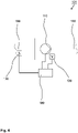
- FIG 1 shows a first embodiment of a pumping device 101 according to the invention schematically.
- the pumping device 101 for pumping liquids comprises a centrifugal pump 110 with a radially pumping impeller with a hollow center.
- At least one first operating parameter 510 can be assigned to the pump 110 at any time during operation.
- liquid lines 150, 155 are connected to the pumping device 101:
- a first line 150 carries the pump medium, ie the liquid to be pumped, to the centrifugal pump 110 and a second line 155 carries the liquid to be pumped from of the centrifugal pump 110.
- the first line 150 is therefore seen from the pump 110 upstream, while the second line 155 seen from the pump 110 runs downstream.
- the pump device also has a detection device 120 for detecting the first operating parameter 510 .
- the sensing device 120 is attached to or located near the pump 110 .
- An example of such a device has a Hall sensor, for example, which, in the case of a pump 110, causes magnetic fields that change over time as a result of its operation.
- a on or in Hall sensor arranged in the vicinity of the pump 110 can be used to register the change in magnetic fields and thus allow conclusions to be drawn about the operating state of the pump 110.
- the device 101 has a sensor 130 for measuring a second operating parameter 520 of the device 101 .
- the senor 130 is arranged downstream of the device 101 on the device 101, in the immediate vicinity of the device 101 or close to the device 101 on or in the second line 155 running downstream.
- the device has a control unit 180 for controlling the centrifugal pump 110 .
- This control unit 180 of the device 101 is connected to the pump 110, to the detection device 120 for detecting the first operating parameter 510 of the device 101 and to the sensor 130 for measuring the second operating parameter 520 of the device 101.
- the control unit 180 controls the operation of the pump 110. It is conceivable that the control unit 180 controls the operation of the entire device 101.
- the controller 180 is set up to remove accumulations of gas from the hollow center of the pump 110 during operation of the device 101 or during operation of the pump 110 .
- the control unit 180 is set up to be able to remove gas accumulations by operating the pump 110 in a first step for gas removal and in doing so the first operating parameter 510 of the pump 110 is varied over time.
- the first operating parameter 510 can be varied, for example, in the form of a ramp or in steps. While the pump 110 is being operated and the first operating parameter 510 is being varied, the second operating parameter 520 is also measured with the sensor 130 .
- values of second operating parameter 520 are obtained as a function of the values of first operating parameter 510.
- the pump speed per unit of time is varied as first operating parameter 510, and structure-borne noise is measured as second operating parameter.
- extrema E are searched for in the previously recorded values of the second operating parameter 520 .
- the values of the first operating parameter 510 that were present when the extreme values E of the second operating parameter 520 were measured are determined in a third step.
- a fourth step for removing gas accumulations - in short: for gas removal - the pump 110 is operated in such a way that it again assumes the operating conditions for a predetermined period of time T that were present when the extremal values E of the second operating parameter 520 were measured.
- the pump 110 therefore assumes the values of the first operating parameter 510, which have been assigned to the extreme values of the second operating parameter 520, for a predetermined period of time, for example for 5 seconds.
- figure 2 shows a further embodiment of a pumping device 101 according to the invention schematically.
- figure 2 shows the same components as figure 1 , but the detection device 120 for detecting the first operating parameter 510 is indicated in the immediate vicinity of the control device 180 or as part of the control device 180.
- the first operating parameter is a parameter of the pump 180 which the control device 180 already detects during operation or which is present to the control device 180 at least as a signal during operation.
- the first operating parameter is a pump current or a bearing current of a pump 110, for example a magnetically levitating impeller pump 110.
- the parameter is a pump frequency or the revolutions of a pump 110 per unit time, eg revolutions per minute or per second.
- figure 3 shows a further embodiment of a pumping device 101 according to the invention schematically.
- figure 3 shows a pumping device with the same components as those in FIG figure 1 shown, but the sensor 130 for measuring a second operating parameter 520 is different from that in figure 1 shown embodiment spaced from the pump 110 (and an optional pump housing surrounding the pump 110) and spaced from the controller 180 on or in a fluid line leading away from the pump.
- the sensor is therefore downstream of the pump with respect to the direction of flow of the liquid being pumped.
- the second operating parameter measured here could be structure-borne noise and/or noise in the liquid, for example.
- figure 4 shows a further embodiment of a pumping device 101 according to the invention schematically.
- figure 4 shows a pumping device with the same components as those in FIG figure 1 shown, but the sensor 130 for measuring a second operating parameter 520 is different from that in figure 1 shown embodiment spaced from the pump 110 (and an optional pump housing surrounding the pump 110) and spaced from the controller 180 on or in a fluid line leading to the pump.
- the sensor is therefore upstream of the pump with respect to the direction of flow of the pumped liquid.
- the second operating parameter measured here could be structure-borne noise and/or noise in the liquid, for example.
- figure 5 12 shows an exemplary hollow center impeller 201 for radial pumping.
- a pumping device 101 for pumping liquids with a centrifugal pump 110 with a radially pumping impeller 201 with a hollow center could have such an impeller 201, for example.
- figure 5 a is an isometric view of an impeller 201
- Figure 5b 1 is a partial cross-sectional view of the same impeller 201.
- the exemplary impeller 201 can be described as two substantially circular discs 210, 220 lying parallel to one another.
- the circular discs 210, 220 may each have a central hole 215, 225, ie a hole 215, 225 at and around the center.
- At least one of the circular disks 210, 220 is designed as a solid circular disk and the other circular disk 220, 210 has a central hole 225, 215.
- the impeller has only one disk 210, 220 and the blades 260 are each free at the end remote from the disk.
- the impeller has two discs 210, 220 which do not have a central recess. The two disks 210, 220 are connected to pump blades 260, which can extend between the first disk 210 and the second disk 220 as radial struts.
- the blades 260 shown have a radial component related to the rotation, a tangential component and a bend, so they are not straight and therefore do not run purely radially and not purely tangentially, but “diagonally”—so to speak, with a radial and tangential component.
- the hollow center of the pump 110 extends in particular in the area spanned by the hole 215 in the first disk 210 and the hole 225 in the second disk 220 in the illustration shown. In all of the embodiments, however, it is characteristic of the hollow center of the pump 110 that the pump blades 260 (including blade blades) just do not reach into the hollow center.
- the hollow center of the pump 110 is thus the area on the axis of rotation of the impeller and/or immediately thereabout which is free of impeller vanes. This area is also not filled by a solid body, but the liquid to be pumped and also the undesired gas accumulations in it can flow through it freely. It is conceivable that a solid body, for example an axle or a shaft, runs directly on the axis of rotation. In this case, the hollow center is the area between the axle or shaft and the pump blades through which the liquid to be pumped can freely flow.
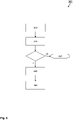
- FIG. 3 shows a further exemplary embodiment of a method 301 according to the invention for removing gas accumulations from the interior of centrifugal pumps 110 with a radially pumping impeller 201 with a hollow center as a flow chart.
- the pump 110 is continuously operated in such a way that an operating parameter of the device 101 is checked 305 continuously or at predetermined time intervals during regular operation.
- the checked parameter can be the first operating parameter 510, for example. Based on the values or the change in the values of this operating parameter, it is recognized when there are gas accumulations inside the pump 110 .
- the values of the operating parameter can be compared with predetermined recognition profiles, for example.
- a predetermined threshold value of the parameter is used as an indication that there is a gas accumulation inside the pump 110 .
- a course of the development of the parameter ie its trend, can be used to determine whether there is a gas accumulation inside the pump 110 . If no gas accumulation is detected during the check 305 of the parameter O, regular operation is continued, which includes a continuation of the check 305 .
- steps are taken to remove the accumulation of gas, as in connection with figure 6 described: varying the first parameter 310, detecting 320 the first parameter 510 and the second parameter 520, determining 330 extremes E of the second parameter 520, determining the values 510(E) of the first parameter 510 assigned to the extremes E of the second parameter 520 , Operating the pump 110 for a predetermined period of time T, the pump 110 assuming a determined value 510(E) of the first parameter 510 that is associated with the extremes E of the second parameter 520. In the variant shown here, after these steps have been carried out, it is optionally additionally checked whether a gas accumulation in the pump 110 is still detected.
- figure 8 shows, by way of example, the variation of the first operating parameter 510 over time t in the form of an idealized step function (as a solid line), in which the first operating parameter 510 assumes increasing values over time t. while showing figure 8 a, for example, an extremum E of an exemplary, simultaneously recorded second operating parameter 520, which is a minimum, and Figure 8b shows an exemplary simultaneous course of an exemplary second operating parameter 520, which forms an extreme E in the form of a maximum.
- the vertical axis on the left corresponds to the magnitude of the value of the first operational parameter 510 in arbitrary units and the horizontal axis corresponds to time t.
- the broken line curve shows the change in the second operating parameter 520 as the first operating parameter 510 is varied as shown.
- the right vertical axis in broken line shows the magnitude of the value of the second operating parameter 520.
- an extremum E of the second operating parameter 520 occurs when the first operating parameter 510 assumes a certain value 510(E).
Landscapes
- Engineering & Computer Science (AREA)
- Health & Medical Sciences (AREA)
- Mechanical Engineering (AREA)
- Heart & Thoracic Surgery (AREA)
- Cardiology (AREA)
- General Engineering & Computer Science (AREA)
- Biomedical Technology (AREA)
- Anesthesiology (AREA)
- Hematology (AREA)
- Life Sciences & Earth Sciences (AREA)
- Animal Behavior & Ethology (AREA)
- General Health & Medical Sciences (AREA)
- Public Health (AREA)
- Veterinary Medicine (AREA)
- Physics & Mathematics (AREA)
- Electromagnetism (AREA)
- Pulmonology (AREA)
- Urology & Nephrology (AREA)
- Structures Of Non-Positive Displacement Pumps (AREA)
- Control Of Non-Positive-Displacement Pumps (AREA)
- External Artificial Organs (AREA)
Claims (12)
- Dispositif de pompage (101) servant au pompage de liquides comprenanta. une pompe centrifuge (110) dotée d'une roue de pompe (201) pompant radialement présentant un centre creux, une valeur d'un premier paramètre de fonctionnement (510) pouvant être associée à la pompe (110) à chaque instant lors du fonctionnement,b. un dispositif de détection (120) servant à la détection du premier paramètre de fonctionnement (510),c. un capteur (130) servant à la mesure d'un deuxième paramètre de fonctionnement (520),d. et un appareil de commande (180) servant à la commande de la pompe centrifuge (110), lequel est connecté à la pompe (110), au dispositif de détection (120) servant la détection du premier paramètre de fonctionnement (510) et au capteur (130), en outre conçu de telle sorte qu'il commande le fonctionnement de la pompe (110) et de telle sorte qu'il peut éliminer des accumulations de gaz du centre creux de la pompe (110) pendant le fonctionnement de refoulement de liquide de la pompe (110), par le fait queo dans une première étape (310) d'élimination de gaz, la pompe (110) fonctionne de telle sorte qu'au moins le premier paramètre de fonctionnement (510) de la pompe (110) est modifié au cours du temps (t) de telle sorte que le premier paramètre de fonctionnement (510) adopte tour à tour une série de différentes valeurs prédéfinies,▪ et de telle sorte que pendant ce temps des valeurs du deuxième paramètre de fonctionnement (520) associées aux valeurs du premier paramètre de fonctionnement (510) sont enregistrées,o dans une deuxième étape (320) d'élimination de gaz, des extrema locaux et/ou globaux (E) des valeurs préalablement enregistrées du deuxième paramètre de fonctionnement (520) sont déterminées,o dans une troisième étape (330) d'élimination de gaz, les valeurs (510(E)) du premier paramètre de fonctionnement (510) qui sont associées aux extrema (E) préalablement déterminés du deuxième paramètre de fonctionnement (520) sont déterminées,o dans une quatrième étape (340) d'élimination de gaz, la pompe (110) fonctionne de telle sorte qu'elle adopte pendant une durée prédéfinie (T) l'une des valeurs du premier paramètre de fonctionnement (510) associées aux extrema (E) du deuxième paramètre de fonctionnement (520).
- Dispositif de pompage (101) selon la revendication 1, conçu de telle sorte que le premier paramètre de fonctionnement (510) est une vitesse de rotation de pompe par unité de temps ou une fréquence de pompe de la pompe centrifuge (110).
- Dispositif de pompage (101) selon l'une des revendications précédentes, le deuxième paramètre de fonctionnement (520) étant le bruit de structure ou le bruit, mesuré directement ou indirectement au niveau du dispositif de pompage, dans le liquide à pomper.
- Dispositif de pompage (101) selon l'une des revendications précédentes, la pompe étant entraînée électriquement et un premier paramètre de fonctionnement (510) étant un courant de fonctionnement électrique de la pompe (110) ou un courant de fonctionnement par vitesse de rotation de la pompe (110).
- Dispositif de pompage (101) selon la revendication 4, la pompe (110) étant une pompe à rotor (110) lévitant magnétiquement et un premier paramètre de fonctionnement (510) étant un courant de palier de la pompe (110) ou un courant de palier par vitesse de rotation de la pompe (110) .
- Dispositif de pompage (101) selon l'une des revendications précédentes, l'appareil de commande (180) étant conçu pour mettre en œuvre la quatrième étape (340) pour plusieurs valeurs différentes du premier paramètre de fonctionnement (510), associées aux extrema (E) du deuxième paramètre de fonctionnement (520).
- Dispositif de pompage (101) selon l'une des revendications précédentes, l'appareil de commande (180) étant conçu pour, après la mise en œuvre de la quatrième étape (340), éliminer à nouveau des accumulations de gaz indésirables, par le fait que les étapes d'élimination d'accumulation de gaz de la première étape (310) à la quatrième étape (340) sont réalisées à nouveau, les valeurs enregistrées du premier paramètre de fonctionnement (510) de différentes itérations pouvant être différentes.
- Dispositif de pompage (101) selon l'une des revendications précédentes, l'appareil de commande (180) étant conçu pour modifier le premier paramètre de fonctionnement (510) dans la première étape (310) de manière linéaire ou par bonds à des intervalles fixes ou comme emboîtement d'intervalles, lesquels se rapprochent d'une valeur prédéfinie à une vitesse prédéfinie.
- Dispositif de pompage (101) selon l'une des revendications précédentes, l'appareil de commande (180) étant conçu pour détecter la présence d'une accumulation de gaz indésirable à l'intérieur de la pompe (110), par le fait que lors du fonctionnement de la pompe (110), le premier paramètre de fonctionnement (510) de la pompe (110) est surveillé (305) de manière continue ou à des intervalles de temps prédéfinis et sa variation au cours du temps est comparée à des profils de détection prédéfinis, et pour mettre en œuvre l'élimination d'accumulations de gaz lors de la détection d'une accumulation de gaz.
- Dispositif de pompage (101) selon l'une des revendications précédentes, l'appareil de commande (180) étant conçu pour continuer le fonctionnement de refoulement de liquide normal si aucuns extrema (E) n'ont été découverts lors de l'élimination d'accumulations de gaz dans la deuxième étape.
- Dispositif de pompage (101) pour le transport de sang et/ou de liquide de traitement médical et/ou de déchets liquides de traitement médicaux selon l'une des revendications 1 à 10.
- Procédé (301) d'élimination d'accumulations de gaz de l'intérieur de pompes centrifuges (110) dotées d'une roue de pompe (201) pompant radialement présentant un centre creux comportant au moins les étapes de procédé suivantes :a. fonctionnement (310) d'une pompe centrifuge, un premier paramètre de fonctionnement (510) de la pompe (110) étant modifié de telle sorte que le premier paramètre de fonctionnement (510) adopte tour à tour une série de différentes valeurs prédéfinies,i. pendant ce temps, pour chaque valeur du premier paramètre de fonctionnement (510), au moins une valeur d'un deuxième paramètre de fonctionnement (520) est enregistrée,b. détermination (320) d'extrema locaux et/ou globaux (E) des valeurs préalablement enregistrées du deuxième paramètre de fonctionnement (520),c. détermination (330) des valeurs du premier paramètre de fonctionnement (510) qui sont associées aux extrema (E) préalablement déterminés du deuxième paramètre de fonctionnement (520),d. fonctionnement (340) de la pompe de telle sorte qu'elle adopte pendant une durée prédéfinie l'une des valeurs du premier paramètre de fonctionnement (510) associées aux extrema (E) du deuxième paramètre de fonctionnement (520).
Applications Claiming Priority (2)
| Application Number | Priority Date | Filing Date | Title |
|---|---|---|---|
| DE102018006877.4A DE102018006877A1 (de) | 2018-08-30 | 2018-08-30 | Pumpvorrichtung zum Pumpen von Flüssigkeiten aufweisend eine Zentrifugalpumpe mit radial pumpendem Pumpenrad mit hohlem Zentrum |
| PCT/EP2019/073055 WO2020043811A1 (fr) | 2018-08-30 | 2019-08-29 | Utilisation d'une pompe centrifuge pour éliminer des accumulations de gaz |
Publications (2)
| Publication Number | Publication Date |
|---|---|
| EP3844397A1 EP3844397A1 (fr) | 2021-07-07 |
| EP3844397B1 true EP3844397B1 (fr) | 2022-10-12 |
Family
ID=67851104
Family Applications (1)
| Application Number | Title | Priority Date | Filing Date |
|---|---|---|---|
| EP19762922.3A Active EP3844397B1 (fr) | 2018-08-30 | 2019-08-29 | Régime de fonctionnement d'une pompe centrifuge pour l'élimination d'accumulations de gaz |
Country Status (5)
| Country | Link |
|---|---|
| US (1) | US11982295B2 (fr) |
| EP (1) | EP3844397B1 (fr) |
| CN (1) | CN112639292B (fr) |
| DE (1) | DE102018006877A1 (fr) |
| WO (1) | WO2020043811A1 (fr) |
Family Cites Families (9)
| Publication number | Priority date | Publication date | Assignee | Title |
|---|---|---|---|---|
| US5873257A (en) * | 1996-08-01 | 1999-02-23 | Smart Power Systems, Inc. | System and method of preventing a surge condition in a vane-type compressor |
| US7945411B2 (en) * | 2006-03-08 | 2011-05-17 | Itt Manufacturing Enterprises, Inc | Method for determining pump flow without the use of traditional sensors |
| US7798215B2 (en) * | 2007-06-26 | 2010-09-21 | Baker Hughes Incorporated | Device, method and program product to automatically detect and break gas locks in an ESP |
| MY183956A (en) * | 2012-03-02 | 2021-03-17 | Shell Int Research | Method of detecting and breaking gas locks in an electric submersible pump |
| NO3018132T3 (fr) * | 2013-04-22 | 2018-05-12 | ||
| DE102013017828B4 (de) * | 2013-10-24 | 2015-05-13 | Fresenius Medical Care Deutschland Gmbh | Verfahren und Vorrichtung zur Überwachung einer in einem extrakorporalen Blutkreislauf oder einer in einem Dialysatkreislauf angeordneten Impellerpumpe und Blutbehandlungsvorrichtung |
| US20160238263A1 (en) * | 2015-02-17 | 2016-08-18 | Air Innovations, Inc. | Low noise micro environmental workspace comfort unit |
| EP3293397B1 (fr) * | 2016-09-13 | 2018-10-24 | Grundfos Holding A/S | Pompe centrifuge et procédé de purge d'air |
| DE102017201008B3 (de) * | 2017-01-23 | 2018-06-21 | BSH Hausgeräte GmbH | Wäschepflegegerät mit einer Steuerung |
-
2018
- 2018-08-30 DE DE102018006877.4A patent/DE102018006877A1/de not_active Withdrawn
-
2019
- 2019-08-29 US US17/254,374 patent/US11982295B2/en active Active
- 2019-08-29 CN CN201980057154.5A patent/CN112639292B/zh active Active
- 2019-08-29 EP EP19762922.3A patent/EP3844397B1/fr active Active
- 2019-08-29 WO PCT/EP2019/073055 patent/WO2020043811A1/fr not_active Ceased
Also Published As
| Publication number | Publication date |
|---|---|
| US11982295B2 (en) | 2024-05-14 |
| EP3844397A1 (fr) | 2021-07-07 |
| WO2020043811A1 (fr) | 2020-03-05 |
| US20210268263A1 (en) | 2021-09-02 |
| DE102018006877A1 (de) | 2020-03-05 |
| CN112639292A (zh) | 2021-04-09 |
| CN112639292B (zh) | 2023-11-07 |
Similar Documents
| Publication | Publication Date | Title |
|---|---|---|
| EP3060808B1 (fr) | Procédé de surveillance d'une pompe à rotor utilisée pour une application médicale | |
| EP1564411B1 (fr) | Procédé de détection des erreurs de fonctionnement d'une unité de pompage | |
| DE60111508T2 (de) | Herzkammerunterstützungssystem mit zweitem laufrad | |
| EP3078390B1 (fr) | Procede de surveillance d'acheminement de fluide dans un dispositif de traitement de sang extracorporel | |
| WO2016207066A1 (fr) | Dispositif et procédé de mesure de pression au niveau du cœur d'un patient | |
| DE202014103883U1 (de) | Vakuumsystem mit optimierter Beschleunigung | |
| DE19613388A1 (de) | Magnetisch gelagerte Art von Pumpe | |
| EP2187992A2 (fr) | Procédé permettant de contrôler et/ou de surveiller le fonctionnement correct d'un dispositif d'addition | |
| EP2736561B1 (fr) | Procédé et dispositifs pour détacher des amas gazeux d'un piège à caillots d'une circulation sanguine extra-corporelle | |
| EP2791511B1 (fr) | Pompe à vide à anneau liquide pourvue d'un réglage de cavitation | |
| DE3605958A1 (de) | Vorrichtung zum erfassen und beheben von abloeseschwingungen an verdichterschaufeln | |
| WO2016166114A1 (fr) | Pompe et procédé pour faire fonctionner une pompe pour liquides | |
| DE102010002133B4 (de) | Sicherheitseinrichtung für eine Schlauchrollenpumpe | |
| WO2022263370A1 (fr) | Pompe et véhicule comprenant une telle pompe | |
| EP2547376B1 (fr) | Dispositif de régulation d'au moins une valeur de filtration et hémodialyseur avec un tel dispositif | |
| EP3844397A1 (fr) | Utilisation d'une pompe centrifuge pour éliminer des accumulations de gaz | |
| EP3507409B1 (fr) | Appareil d'entretien du linge doté d'une commande | |
| WO2015067582A1 (fr) | Pompe pour liquide épais équipée d'une unité d'amenée réversible | |
| DE2754840B2 (de) | Kreiselpumpe | |
| EP3821972B1 (fr) | Utilisation d'un module filtrant pour filtrer un liquide biotechnologique et module filtrant permettant de filtrer un liquide biotechnologique | |
| EP3934711A1 (fr) | Ensemble de conduites sanguines extracorporelles et machine de traitement du sang | |
| EP4390141A1 (fr) | Procédé de détection et/ou de classification pour libérer une obstruction d'une pompe d'eaux usées | |
| EP2466145A2 (fr) | Procédé d'aération d'une pompe à vide et agencement doté d'une pompe à vide | |
| DE102004044185A1 (de) | Verfahren und Vorrichtung zum Ermitteln eines Fehlerzustandes eines rotierenden Verdichters | |
| BE1031871B1 (de) | Verfahren zum Lösen einer Verstopfung einer Kreiselpumpe und Kreiselpumpe |
Legal Events
| Date | Code | Title | Description |
|---|---|---|---|
| STAA | Information on the status of an ep patent application or granted ep patent |
Free format text: STATUS: UNKNOWN |
|
| STAA | Information on the status of an ep patent application or granted ep patent |
Free format text: STATUS: THE INTERNATIONAL PUBLICATION HAS BEEN MADE |
|
| STAA | Information on the status of an ep patent application or granted ep patent |
Free format text: STATUS: REQUEST FOR EXAMINATION WAS MADE |
|
| PUAI | Public reference made under article 153(3) epc to a published international application that has entered the european phase |
Free format text: ORIGINAL CODE: 0009012 |
|
| 17P | Request for examination filed |
Effective date: 20210330 |
|
| AK | Designated contracting states |
Kind code of ref document: A1 Designated state(s): AL AT BE BG CH CY CZ DE DK EE ES FI FR GB GR HR HU IE IS IT LI LT LU LV MC MK MT NL NO PL PT RO RS SE SI SK SM TR |
|
| DAV | Request for validation of the european patent (deleted) | ||
| DAX | Request for extension of the european patent (deleted) | ||
| GRAP | Despatch of communication of intention to grant a patent |
Free format text: ORIGINAL CODE: EPIDOSNIGR1 |
|
| STAA | Information on the status of an ep patent application or granted ep patent |
Free format text: STATUS: GRANT OF PATENT IS INTENDED |
|
| RIC1 | Information provided on ipc code assigned before grant |
Ipc: A61M 60/50 20210101ALI20220402BHEP Ipc: F04D 29/66 20060101ALI20220402BHEP Ipc: F04D 15/00 20060101ALI20220402BHEP Ipc: F04D 9/00 20060101AFI20220402BHEP |
|
| INTG | Intention to grant announced |
Effective date: 20220506 |
|
| GRAS | Grant fee paid |
Free format text: ORIGINAL CODE: EPIDOSNIGR3 |
|
| GRAA | (expected) grant |
Free format text: ORIGINAL CODE: 0009210 |
|
| STAA | Information on the status of an ep patent application or granted ep patent |
Free format text: STATUS: THE PATENT HAS BEEN GRANTED |
|
| AK | Designated contracting states |
Kind code of ref document: B1 Designated state(s): AL AT BE BG CH CY CZ DE DK EE ES FI FR GB GR HR HU IE IS IT LI LT LU LV MC MK MT NL NO PL PT RO RS SE SI SK SM TR |
|
| REG | Reference to a national code |
Ref country code: GB Ref legal event code: FG4D Free format text: NOT ENGLISH |
|
| REG | Reference to a national code |
Ref country code: CH Ref legal event code: EP |
|
| REG | Reference to a national code |
Ref country code: DE Ref legal event code: R096 Ref document number: 502019005923 Country of ref document: DE |
|
| REG | Reference to a national code |
Ref country code: IE Ref legal event code: FG4D Free format text: LANGUAGE OF EP DOCUMENT: GERMAN |
|
| REG | Reference to a national code |
Ref country code: AT Ref legal event code: REF Ref document number: 1524328 Country of ref document: AT Kind code of ref document: T Effective date: 20221115 |
|
| REG | Reference to a national code |
Ref country code: LT Ref legal event code: MG9D |
|
| REG | Reference to a national code |
Ref country code: NL Ref legal event code: MP Effective date: 20221012 |
|
| PG25 | Lapsed in a contracting state [announced via postgrant information from national office to epo] |
Ref country code: NL Free format text: LAPSE BECAUSE OF FAILURE TO SUBMIT A TRANSLATION OF THE DESCRIPTION OR TO PAY THE FEE WITHIN THE PRESCRIBED TIME-LIMIT Effective date: 20221012 |
|
| PG25 | Lapsed in a contracting state [announced via postgrant information from national office to epo] |
Ref country code: SE Free format text: LAPSE BECAUSE OF FAILURE TO SUBMIT A TRANSLATION OF THE DESCRIPTION OR TO PAY THE FEE WITHIN THE PRESCRIBED TIME-LIMIT Effective date: 20221012 Ref country code: PT Free format text: LAPSE BECAUSE OF FAILURE TO SUBMIT A TRANSLATION OF THE DESCRIPTION OR TO PAY THE FEE WITHIN THE PRESCRIBED TIME-LIMIT Effective date: 20230213 Ref country code: NO Free format text: LAPSE BECAUSE OF FAILURE TO SUBMIT A TRANSLATION OF THE DESCRIPTION OR TO PAY THE FEE WITHIN THE PRESCRIBED TIME-LIMIT Effective date: 20230112 Ref country code: LT Free format text: LAPSE BECAUSE OF FAILURE TO SUBMIT A TRANSLATION OF THE DESCRIPTION OR TO PAY THE FEE WITHIN THE PRESCRIBED TIME-LIMIT Effective date: 20221012 Ref country code: FI Free format text: LAPSE BECAUSE OF FAILURE TO SUBMIT A TRANSLATION OF THE DESCRIPTION OR TO PAY THE FEE WITHIN THE PRESCRIBED TIME-LIMIT Effective date: 20221012 Ref country code: ES Free format text: LAPSE BECAUSE OF FAILURE TO SUBMIT A TRANSLATION OF THE DESCRIPTION OR TO PAY THE FEE WITHIN THE PRESCRIBED TIME-LIMIT Effective date: 20221012 |
|
| PG25 | Lapsed in a contracting state [announced via postgrant information from national office to epo] |
Ref country code: RS Free format text: LAPSE BECAUSE OF FAILURE TO SUBMIT A TRANSLATION OF THE DESCRIPTION OR TO PAY THE FEE WITHIN THE PRESCRIBED TIME-LIMIT Effective date: 20221012 Ref country code: PL Free format text: LAPSE BECAUSE OF FAILURE TO SUBMIT A TRANSLATION OF THE DESCRIPTION OR TO PAY THE FEE WITHIN THE PRESCRIBED TIME-LIMIT Effective date: 20221012 Ref country code: LV Free format text: LAPSE BECAUSE OF FAILURE TO SUBMIT A TRANSLATION OF THE DESCRIPTION OR TO PAY THE FEE WITHIN THE PRESCRIBED TIME-LIMIT Effective date: 20221012 Ref country code: IS Free format text: LAPSE BECAUSE OF FAILURE TO SUBMIT A TRANSLATION OF THE DESCRIPTION OR TO PAY THE FEE WITHIN THE PRESCRIBED TIME-LIMIT Effective date: 20230212 Ref country code: HR Free format text: LAPSE BECAUSE OF FAILURE TO SUBMIT A TRANSLATION OF THE DESCRIPTION OR TO PAY THE FEE WITHIN THE PRESCRIBED TIME-LIMIT Effective date: 20221012 Ref country code: GR Free format text: LAPSE BECAUSE OF FAILURE TO SUBMIT A TRANSLATION OF THE DESCRIPTION OR TO PAY THE FEE WITHIN THE PRESCRIBED TIME-LIMIT Effective date: 20230113 |
|
| P01 | Opt-out of the competence of the unified patent court (upc) registered |
Effective date: 20230602 |
|
| REG | Reference to a national code |
Ref country code: DE Ref legal event code: R097 Ref document number: 502019005923 Country of ref document: DE |
|
| PG25 | Lapsed in a contracting state [announced via postgrant information from national office to epo] |
Ref country code: SM Free format text: LAPSE BECAUSE OF FAILURE TO SUBMIT A TRANSLATION OF THE DESCRIPTION OR TO PAY THE FEE WITHIN THE PRESCRIBED TIME-LIMIT Effective date: 20221012 Ref country code: RO Free format text: LAPSE BECAUSE OF FAILURE TO SUBMIT A TRANSLATION OF THE DESCRIPTION OR TO PAY THE FEE WITHIN THE PRESCRIBED TIME-LIMIT Effective date: 20221012 Ref country code: EE Free format text: LAPSE BECAUSE OF FAILURE TO SUBMIT A TRANSLATION OF THE DESCRIPTION OR TO PAY THE FEE WITHIN THE PRESCRIBED TIME-LIMIT Effective date: 20221012 Ref country code: DK Free format text: LAPSE BECAUSE OF FAILURE TO SUBMIT A TRANSLATION OF THE DESCRIPTION OR TO PAY THE FEE WITHIN THE PRESCRIBED TIME-LIMIT Effective date: 20221012 Ref country code: CZ Free format text: LAPSE BECAUSE OF FAILURE TO SUBMIT A TRANSLATION OF THE DESCRIPTION OR TO PAY THE FEE WITHIN THE PRESCRIBED TIME-LIMIT Effective date: 20221012 |
|
| PLBE | No opposition filed within time limit |
Free format text: ORIGINAL CODE: 0009261 |
|
| STAA | Information on the status of an ep patent application or granted ep patent |
Free format text: STATUS: NO OPPOSITION FILED WITHIN TIME LIMIT |
|
| PG25 | Lapsed in a contracting state [announced via postgrant information from national office to epo] |
Ref country code: SK Free format text: LAPSE BECAUSE OF FAILURE TO SUBMIT A TRANSLATION OF THE DESCRIPTION OR TO PAY THE FEE WITHIN THE PRESCRIBED TIME-LIMIT Effective date: 20221012 Ref country code: AL Free format text: LAPSE BECAUSE OF FAILURE TO SUBMIT A TRANSLATION OF THE DESCRIPTION OR TO PAY THE FEE WITHIN THE PRESCRIBED TIME-LIMIT Effective date: 20221012 |
|
| 26N | No opposition filed |
Effective date: 20230713 |
|
| PG25 | Lapsed in a contracting state [announced via postgrant information from national office to epo] |
Ref country code: SI Free format text: LAPSE BECAUSE OF FAILURE TO SUBMIT A TRANSLATION OF THE DESCRIPTION OR TO PAY THE FEE WITHIN THE PRESCRIBED TIME-LIMIT Effective date: 20221012 |
|
| PG25 | Lapsed in a contracting state [announced via postgrant information from national office to epo] |
Ref country code: MC Free format text: LAPSE BECAUSE OF FAILURE TO SUBMIT A TRANSLATION OF THE DESCRIPTION OR TO PAY THE FEE WITHIN THE PRESCRIBED TIME-LIMIT Effective date: 20221012 |
|
| PG25 | Lapsed in a contracting state [announced via postgrant information from national office to epo] |
Ref country code: MC Free format text: LAPSE BECAUSE OF FAILURE TO SUBMIT A TRANSLATION OF THE DESCRIPTION OR TO PAY THE FEE WITHIN THE PRESCRIBED TIME-LIMIT Effective date: 20221012 |
|
| PG25 | Lapsed in a contracting state [announced via postgrant information from national office to epo] |
Ref country code: LU Free format text: LAPSE BECAUSE OF NON-PAYMENT OF DUE FEES Effective date: 20230829 |
|
| PG25 | Lapsed in a contracting state [announced via postgrant information from national office to epo] |
Ref country code: LU Free format text: LAPSE BECAUSE OF NON-PAYMENT OF DUE FEES Effective date: 20230829 |
|
| REG | Reference to a national code |
Ref country code: BE Ref legal event code: MM Effective date: 20230831 |
|
| REG | Reference to a national code |
Ref country code: IE Ref legal event code: MM4A |
|
| PG25 | Lapsed in a contracting state [announced via postgrant information from national office to epo] |
Ref country code: IT Free format text: LAPSE BECAUSE OF FAILURE TO SUBMIT A TRANSLATION OF THE DESCRIPTION OR TO PAY THE FEE WITHIN THE PRESCRIBED TIME-LIMIT Effective date: 20221012 |
|
| PG25 | Lapsed in a contracting state [announced via postgrant information from national office to epo] |
Ref country code: IE Free format text: LAPSE BECAUSE OF NON-PAYMENT OF DUE FEES Effective date: 20230829 |
|
| PG25 | Lapsed in a contracting state [announced via postgrant information from national office to epo] |
Ref country code: IE Free format text: LAPSE BECAUSE OF NON-PAYMENT OF DUE FEES Effective date: 20230829 |
|
| PG25 | Lapsed in a contracting state [announced via postgrant information from national office to epo] |
Ref country code: BE Free format text: LAPSE BECAUSE OF NON-PAYMENT OF DUE FEES Effective date: 20230831 |
|
| PG25 | Lapsed in a contracting state [announced via postgrant information from national office to epo] |
Ref country code: BG Free format text: LAPSE BECAUSE OF FAILURE TO SUBMIT A TRANSLATION OF THE DESCRIPTION OR TO PAY THE FEE WITHIN THE PRESCRIBED TIME-LIMIT Effective date: 20221012 |
|
| PG25 | Lapsed in a contracting state [announced via postgrant information from national office to epo] |
Ref country code: BG Free format text: LAPSE BECAUSE OF FAILURE TO SUBMIT A TRANSLATION OF THE DESCRIPTION OR TO PAY THE FEE WITHIN THE PRESCRIBED TIME-LIMIT Effective date: 20221012 |
|
| PG25 | Lapsed in a contracting state [announced via postgrant information from national office to epo] |
Ref country code: CY Free format text: LAPSE BECAUSE OF FAILURE TO SUBMIT A TRANSLATION OF THE DESCRIPTION OR TO PAY THE FEE WITHIN THE PRESCRIBED TIME-LIMIT; INVALID AB INITIO Effective date: 20190829 |
|
| PG25 | Lapsed in a contracting state [announced via postgrant information from national office to epo] |
Ref country code: HU Free format text: LAPSE BECAUSE OF FAILURE TO SUBMIT A TRANSLATION OF THE DESCRIPTION OR TO PAY THE FEE WITHIN THE PRESCRIBED TIME-LIMIT; INVALID AB INITIO Effective date: 20190829 |
|
| PGFP | Annual fee paid to national office [announced via postgrant information from national office to epo] |
Ref country code: DE Payment date: 20250724 Year of fee payment: 7 |
|
| REG | Reference to a national code |
Ref country code: AT Ref legal event code: MM01 Ref document number: 1524328 Country of ref document: AT Kind code of ref document: T Effective date: 20240829 |
|
| PGFP | Annual fee paid to national office [announced via postgrant information from national office to epo] |
Ref country code: GB Payment date: 20250724 Year of fee payment: 7 |
|
| PG25 | Lapsed in a contracting state [announced via postgrant information from national office to epo] |
Ref country code: AT Free format text: LAPSE BECAUSE OF NON-PAYMENT OF DUE FEES Effective date: 20240829 |
|
| PGFP | Annual fee paid to national office [announced via postgrant information from national office to epo] |
Ref country code: FR Payment date: 20250723 Year of fee payment: 7 |
|
| PGFP | Annual fee paid to national office [announced via postgrant information from national office to epo] |
Ref country code: CH Payment date: 20250901 Year of fee payment: 7 |
|
| PG25 | Lapsed in a contracting state [announced via postgrant information from national office to epo] |
Ref country code: TR Free format text: LAPSE BECAUSE OF FAILURE TO SUBMIT A TRANSLATION OF THE DESCRIPTION OR TO PAY THE FEE WITHIN THE PRESCRIBED TIME-LIMIT Effective date: 20221012 |
|
| PGFP | Annual fee paid to national office [announced via postgrant information from national office to epo] |
Ref country code: AT Payment date: 20260410 Year of fee payment: 5 |