EP3293397B1 - Pompe centrifuge et procédé de purge d'air - Google Patents
Pompe centrifuge et procédé de purge d'air Download PDFInfo
- Publication number
- EP3293397B1 EP3293397B1 EP16188626.2A EP16188626A EP3293397B1 EP 3293397 B1 EP3293397 B1 EP 3293397B1 EP 16188626 A EP16188626 A EP 16188626A EP 3293397 B1 EP3293397 B1 EP 3293397B1
- Authority
- EP
- European Patent Office
- Prior art keywords
- centrifugal pump
- pump assembly
- speed
- pressure
- control device
- Prior art date
- Legal status (The legal status is an assumption and is not a legal conclusion. Google has not performed a legal analysis and makes no representation as to the accuracy of the status listed.)
- Active
Links
- 238000013022 venting Methods 0.000 title claims description 14
- 238000000034 method Methods 0.000 title claims description 13
- 238000009825 accumulation Methods 0.000 claims description 50
- XLYOFNOQVPJJNP-UHFFFAOYSA-N water Substances O XLYOFNOQVPJJNP-UHFFFAOYSA-N 0.000 claims description 15
- 230000001419 dependent effect Effects 0.000 claims description 5
- 238000001514 detection method Methods 0.000 claims description 4
- 238000012544 monitoring process Methods 0.000 claims description 3
- 230000035508 accumulation Effects 0.000 description 43
- 239000007789 gas Substances 0.000 description 30
- 239000007788 liquid Substances 0.000 description 7
- 238000010586 diagram Methods 0.000 description 6
- 230000007423 decrease Effects 0.000 description 5
- 238000010926 purge Methods 0.000 description 3
- 230000001133 acceleration Effects 0.000 description 1
- 230000003213 activating effect Effects 0.000 description 1
- 239000003570 air Substances 0.000 description 1
- 238000010276 construction Methods 0.000 description 1
- 230000001276 controlling effect Effects 0.000 description 1
- 239000003651 drinking water Substances 0.000 description 1
- 235000020188 drinking water Nutrition 0.000 description 1
- 230000009760 functional impairment Effects 0.000 description 1
- 239000000203 mixture Substances 0.000 description 1
- 238000010992 reflux Methods 0.000 description 1
- 230000001105 regulatory effect Effects 0.000 description 1
Images


Classifications
-
- F—MECHANICAL ENGINEERING; LIGHTING; HEATING; WEAPONS; BLASTING
- F04—POSITIVE - DISPLACEMENT MACHINES FOR LIQUIDS; PUMPS FOR LIQUIDS OR ELASTIC FLUIDS
- F04D—NON-POSITIVE-DISPLACEMENT PUMPS
- F04D15/00—Control, e.g. regulation, of pumps, pumping installations or systems
- F04D15/0066—Control, e.g. regulation, of pumps, pumping installations or systems by changing the speed, e.g. of the driving engine
-
- F—MECHANICAL ENGINEERING; LIGHTING; HEATING; WEAPONS; BLASTING
- F04—POSITIVE - DISPLACEMENT MACHINES FOR LIQUIDS; PUMPS FOR LIQUIDS OR ELASTIC FLUIDS
- F04D—NON-POSITIVE-DISPLACEMENT PUMPS
- F04D9/00—Priming; Preventing vapour lock
- F04D9/001—Preventing vapour lock
- F04D9/002—Preventing vapour lock by means in the very pump
- F04D9/003—Preventing vapour lock by means in the very pump separating and removing the vapour
-
- F—MECHANICAL ENGINEERING; LIGHTING; HEATING; WEAPONS; BLASTING
- F04—POSITIVE - DISPLACEMENT MACHINES FOR LIQUIDS; PUMPS FOR LIQUIDS OR ELASTIC FLUIDS
- F04D—NON-POSITIVE-DISPLACEMENT PUMPS
- F04D1/00—Radial-flow pumps, e.g. centrifugal pumps; Helico-centrifugal pumps
-
- F—MECHANICAL ENGINEERING; LIGHTING; HEATING; WEAPONS; BLASTING
- F04—POSITIVE - DISPLACEMENT MACHINES FOR LIQUIDS; PUMPS FOR LIQUIDS OR ELASTIC FLUIDS
- F04D—NON-POSITIVE-DISPLACEMENT PUMPS
- F04D13/00—Pumping installations or systems
- F04D13/02—Units comprising pumps and their driving means
- F04D13/06—Units comprising pumps and their driving means the pump being electrically driven
- F04D13/0686—Mechanical details of the pump control unit
-
- F—MECHANICAL ENGINEERING; LIGHTING; HEATING; WEAPONS; BLASTING
- F04—POSITIVE - DISPLACEMENT MACHINES FOR LIQUIDS; PUMPS FOR LIQUIDS OR ELASTIC FLUIDS
- F04D—NON-POSITIVE-DISPLACEMENT PUMPS
- F04D13/00—Pumping installations or systems
- F04D13/16—Pumping installations or systems with storage reservoirs
-
- F—MECHANICAL ENGINEERING; LIGHTING; HEATING; WEAPONS; BLASTING
- F04—POSITIVE - DISPLACEMENT MACHINES FOR LIQUIDS; PUMPS FOR LIQUIDS OR ELASTIC FLUIDS
- F04D—NON-POSITIVE-DISPLACEMENT PUMPS
- F04D15/00—Control, e.g. regulation, of pumps, pumping installations or systems
- F04D15/0005—Control, e.g. regulation, of pumps, pumping installations or systems by using valves
- F04D15/0011—Control, e.g. regulation, of pumps, pumping installations or systems by using valves by-pass valves
-
- F—MECHANICAL ENGINEERING; LIGHTING; HEATING; WEAPONS; BLASTING
- F04—POSITIVE - DISPLACEMENT MACHINES FOR LIQUIDS; PUMPS FOR LIQUIDS OR ELASTIC FLUIDS
- F04D—NON-POSITIVE-DISPLACEMENT PUMPS
- F04D15/00—Control, e.g. regulation, of pumps, pumping installations or systems
- F04D15/02—Stopping of pumps, or operating valves, on occurrence of unwanted conditions
- F04D15/0281—Stopping of pumps, or operating valves, on occurrence of unwanted conditions responsive to a condition not otherwise provided for
-
- F—MECHANICAL ENGINEERING; LIGHTING; HEATING; WEAPONS; BLASTING
- F04—POSITIVE - DISPLACEMENT MACHINES FOR LIQUIDS; PUMPS FOR LIQUIDS OR ELASTIC FLUIDS
- F04D—NON-POSITIVE-DISPLACEMENT PUMPS
- F04D27/00—Control, e.g. regulation, of pumps, pumping installations or pumping systems specially adapted for elastic fluids
- F04D27/009—Control, e.g. regulation, of pumps, pumping installations or pumping systems specially adapted for elastic fluids by bleeding, by passing or recycling fluid
-
- F—MECHANICAL ENGINEERING; LIGHTING; HEATING; WEAPONS; BLASTING
- F04—POSITIVE - DISPLACEMENT MACHINES FOR LIQUIDS; PUMPS FOR LIQUIDS OR ELASTIC FLUIDS
- F04D—NON-POSITIVE-DISPLACEMENT PUMPS
- F04D27/00—Control, e.g. regulation, of pumps, pumping installations or pumping systems specially adapted for elastic fluids
- F04D27/02—Surge control
- F04D27/0207—Surge control by bleeding, bypassing or recycling fluids
- F04D27/0215—Arrangements therefor, e.g. bleed or by-pass valves
-
- F—MECHANICAL ENGINEERING; LIGHTING; HEATING; WEAPONS; BLASTING
- F04—POSITIVE - DISPLACEMENT MACHINES FOR LIQUIDS; PUMPS FOR LIQUIDS OR ELASTIC FLUIDS
- F04D—NON-POSITIVE-DISPLACEMENT PUMPS
- F04D27/00—Control, e.g. regulation, of pumps, pumping installations or pumping systems specially adapted for elastic fluids
- F04D27/02—Surge control
- F04D27/0261—Surge control by varying driving speed
-
- F—MECHANICAL ENGINEERING; LIGHTING; HEATING; WEAPONS; BLASTING
- F04—POSITIVE - DISPLACEMENT MACHINES FOR LIQUIDS; PUMPS FOR LIQUIDS OR ELASTIC FLUIDS
- F04D—NON-POSITIVE-DISPLACEMENT PUMPS
- F04D9/00—Priming; Preventing vapour lock
- F04D9/02—Self-priming pumps
-
- F—MECHANICAL ENGINEERING; LIGHTING; HEATING; WEAPONS; BLASTING
- F04—POSITIVE - DISPLACEMENT MACHINES FOR LIQUIDS; PUMPS FOR LIQUIDS OR ELASTIC FLUIDS
- F04D—NON-POSITIVE-DISPLACEMENT PUMPS
- F04D1/00—Radial-flow pumps, e.g. centrifugal pumps; Helico-centrifugal pumps
- F04D1/06—Multi-stage pumps
-
- F—MECHANICAL ENGINEERING; LIGHTING; HEATING; WEAPONS; BLASTING
- F04—POSITIVE - DISPLACEMENT MACHINES FOR LIQUIDS; PUMPS FOR LIQUIDS OR ELASTIC FLUIDS
- F04D—NON-POSITIVE-DISPLACEMENT PUMPS
- F04D13/00—Pumping installations or systems
- F04D13/02—Units comprising pumps and their driving means
- F04D13/06—Units comprising pumps and their driving means the pump being electrically driven
-
- F—MECHANICAL ENGINEERING; LIGHTING; HEATING; WEAPONS; BLASTING
- F04—POSITIVE - DISPLACEMENT MACHINES FOR LIQUIDS; PUMPS FOR LIQUIDS OR ELASTIC FLUIDS
- F04D—NON-POSITIVE-DISPLACEMENT PUMPS
- F04D29/00—Details, component parts, or accessories
- F04D29/40—Casings; Connections of working fluid
- F04D29/42—Casings; Connections of working fluid for radial or helico-centrifugal pumps
- F04D29/426—Casings; Connections of working fluid for radial or helico-centrifugal pumps especially adapted for liquid pumps
-
- F—MECHANICAL ENGINEERING; LIGHTING; HEATING; WEAPONS; BLASTING
- F04—POSITIVE - DISPLACEMENT MACHINES FOR LIQUIDS; PUMPS FOR LIQUIDS OR ELASTIC FLUIDS
- F04D—NON-POSITIVE-DISPLACEMENT PUMPS
- F04D9/00—Priming; Preventing vapour lock
- F04D9/001—Preventing vapour lock
-
- F—MECHANICAL ENGINEERING; LIGHTING; HEATING; WEAPONS; BLASTING
- F04—POSITIVE - DISPLACEMENT MACHINES FOR LIQUIDS; PUMPS FOR LIQUIDS OR ELASTIC FLUIDS
- F04D—NON-POSITIVE-DISPLACEMENT PUMPS
- F04D9/00—Priming; Preventing vapour lock
- F04D9/004—Priming of not self-priming pumps
- F04D9/005—Priming of not self-priming pumps by adducting or recycling liquid
-
- F—MECHANICAL ENGINEERING; LIGHTING; HEATING; WEAPONS; BLASTING
- F04—POSITIVE - DISPLACEMENT MACHINES FOR LIQUIDS; PUMPS FOR LIQUIDS OR ELASTIC FLUIDS
- F04D—NON-POSITIVE-DISPLACEMENT PUMPS
- F04D9/00—Priming; Preventing vapour lock
- F04D9/004—Priming of not self-priming pumps
- F04D9/006—Priming of not self-priming pumps by venting gas or using gas valves
Definitions
- the invention relates to a centrifugal pump unit and in particular a domestic waterworks with such a centrifugal pump unit.
- centrifugal pump units which, for example, convey water from a well, as may be the case with domestic water works, it can happen that air or gas bubbles accumulate during operation in the pump unit. These can arise, for example, when gases dissolved in the water are released. If the thus formed accumulations of air or gas in the centrifugal pump become too large, it may happen that the pump no longer delivers in the desired manner, d. H. that no flow and no pressure build-up are given.
- WO 2014/176225 A1 discloses a method for eliminating air build-up in a submersible pump assembly by lowering the rate of depletion of the gas accumulation and then increasing it again to verify the successful purging of the gas accumulation.
- US 2013/0336763 A1 discloses a pump system having a pump housing having an opening at the top through which air accumulations can escape. In order to favor the accumulation of air near the opening, the pump is turned on and off several times.
- EP 1 013 936 A1 discloses a multi-stage centrifugal pump assembly having a return passage connecting the pressure side to the suction side. Through this return flow channel, a circulating flow can be generated during commissioning of the pump unit. In the return flow channel, a valve is provided, which closes the return flow channel with sufficient pressure build-up.
- the centrifugal pump unit according to the invention has at least one impeller, which is driven in rotation by an electric drive motor.
- the impeller can be connected in a known manner via a shaft to the rotor of the drive motor or be attached directly to the rotor.
- the invention relates to a centrifugal pump unit which has a return flow channel, which constitutes a flow connection which connects the pressure side of the at least one impeller with its suction side.
- a return flow channel is provided to make such a centrifugal pump assembly self-priming or to improve the starting characteristics of the pump.
- liquid can first be conveyed in a circle, wherein at the same time a suction can be generated in the suction channel of the pump unit in order to suck liquid in the suction channel.
- a valve is arranged, which closes pressure-dependent the return flow channel or the flow connection created by this.
- the valve is designed so that it closes the return flow channel at a certain pressure on the pressure side of the impeller.
- This predetermined pressure is the pressure which is reached after venting when the centrifugal pump assembly goes into normal operation. As long as the predetermined pressure is not reached, the valve is open and a return flow through the return flow channel is possible, so that the impeller can initially promote a certain proportion of the flow in a circle.
- the centrifugal pump assembly according to the invention also has a control device, which is designed for setting and in particular for controlling the rotational speed of the drive motor. Ie. The speed of the drive motor can be changed via the control device.
- this control device has a venting function, which is designed to vent the centrifugal pump assembly in operation when an undesirable gas or air accumulation in the centrifugal pump assembly is detected. Becomes such an accumulation of air detected by the control device, which may for example be done in the manner described below, the control device preferably automatically starts a vent function to remove the accumulation of air from the centrifugal pump unit before the centrifugal pump assembly no longer fulfills its desired function.
- the control device is designed so that it automatically reduces the speed of the drive motor after detecting an accumulation of air in a first step. Possibly. the speed can be reduced in this first step to standstill of the drive motor. Following this first step, the speed of the drive motor is increased again in a second step, wherein this is done very quickly according to the invention. Due to the rapid increase in speed, a strong flow is generated, through which the gas bubbles or gas accumulations can be flushed out of the centrifugal pump unit.
- venting function is that in this only a short-term speed reduction must be made in the first step, but otherwise the operation of the centrifugal pump unit is not hindered, so it does not come in a subsequent output to the centrifugal pump assembly system to a complete pressure drop.
- This is particularly advantageous in the use of domestic water works, as always so a sufficient pressure and a sufficient flow in the water system of the building can be achieved.
- the control device is designed such that the rotational speed in the first step is reduced to such an extent that the valve opens in the return flow channel.
- control device is designed such that the speed is increased in the second step to at least 80% of the maximum speed and preferably to the maximum speed.
- the maximum speed is that speed which is provided as the maximum speed for operating the centrifugal pump assembly. Increasing to the maximum speed achieves strong flow in the centrifugal pump assembly to flush out the air accumulation.
- control device is designed such that the speed is increased in the second step in less than three, preferably in less than two and more preferably in less than 1.5 seconds to the maximum speed.
- This strong acceleration ensures that the flow can be formed before the valve closes in the return flow channel.
- a strong pulse is generated, which favors the purging of the gas accumulation from the centrifugal pump unit.
- the control device is designed such that it has a monitoring function to detect the accumulation of air.
- the control device is preferably designed such that an accumulation of air is detected by the fact that the electrical power consumption drops below a predetermined first limit value. This is preferably done at least one, more preferably at a plurality of predetermined rotational speeds, for which in the control device certain first limits for the electrical power consumption are defined. If the electrical power consumption falls below the associated fixed first limit value at the determined speed, an accumulation of air can be detected.
- the specific speed is the maximum speed.
- the maximum speed is that speed, which is provided as the maximum speed for operating the centrifugal pump assembly and is set by the maximum control device.
- the monitoring function may be designed such that, to check whether an air accumulation is present, at predetermined, in particular, regular points in time, the rotational speed is increased to the maximum rotational speed in order to carry out a check of air accumulations. Particularly preferably, the check at the maximum speed results automatically.
- An accumulation of air in the centrifugal pump unit causes the pressure difference across the centrifugal pump unit to decrease.
- the control in the control device is then, if a pressure control is provided, try to compensate by increasing the speed until the maximum speed is reached.
- the comparison is then made with a predetermined threshold for electrical power consumption to determine if there is air buildup.
- this principle can also be used at speeds other than the maximum speed and the control device can be designed accordingly.
- the control device is designed such that the said first limit value for the electrical power consumption is above a second limit value for the electrical power consumption, which is reached or fallen below during a dry run of the centrifugal pump assembly.
- the second limit value thus signals the dry running of the centrifugal pump unit. Because the first and second limits are different, it is possible to to distinguish the accumulation of air to be removed from a complete dry run.
- the control device is further preferably designed so that it falls below the second limit, the centrifugal pump unit out of service, ie the drive motor turns off, in particular to avoid damage to the bearings.
- the centrifugal pump assembly is designed such that the axis of rotation of the drive motor and of the at least one impeller extends horizontally.
- the horizontal extent refers to the intended operating position of the centrifugal pump unit, in which the centrifugal pump unit is set up for operation.
- centrifugal pump units with horizontal axis of rotation there is the problem that air can accumulate in the upper areas inside the housing of the centrifugal pump assembly and the impeller. If flow paths in the interior of the centrifugal pump assembly also extend in the horizontal direction, as is the case with multi-stage pumps in general, the accumulating air can not rise freely up and not escape from the inside of the centrifugal pump units by itself.
- the centrifugal pump assembly can be formed in multiple stages with at least two, preferably driven by a common shaft wheels.
- the wheels are connected in series such that the pressure side of the first impeller is connected to the suction side of the second impeller, so that the second impeller, a further pressure increase takes place starting from the output pressure at the pressure side of the first impeller.
- the return flow channel preferably extends such that the pressure side of a the impellers, preferably the pressure side of the last impeller in the flow direction, is connected to the suction side of the first impeller through the return flow channel.
- the return flow channel branches off between two stages and thus, for example, connects the pressure side of the first impeller to the suction side of the first impeller. This shortens the circuit to be set up for commissioning.
- the invention is in addition to the above-described centrifugal pump unit a domestic waterworks with a centrifugal pump unit according to the foregoing description.
- Domestic water works serve to supply a building with water, in particular drinking water or to increase the pressure in the water supply of a building.
- a domestic waterworks can pump water from a well into the building.
- Such domestic waterworks usually have a pressure accumulator in addition to the pump unit in order to keep a certain operating pressure in the system even when switched off centrifugal pump unit.
- such a domestic waterworks may have a flow sensor and / or pressure switch, which are connected to the control device such that the control device can detect a water requirement by the detected measured values and the centrifugal pump unit, ie its drive motor can turn on, if the pressure on the output side of the centrifugal pump unit under a predetermined limit drops.
- the control device is preferably integrated with the other components of the domestic waterworks to form a unit, ie preferably arranged in an electronics housing, which is integrated directly into the domestic waterworks, for example, is mounted on the motor housing of the drive motor.
- an electronics housing with the control device may also be arranged externally and at a distance from the drive motor and be connected to the latter, for example via a cable connection.
- the house water plant forms a structural unit, which only with a suction or Connecting line, the output side of the centrifugal pump assembly must be connected to a pressure line and a power supply.
- the centrifugal pump unit of the domestic waterworks is preferably designed according to one or more of the preferred embodiments described above.
- the invention further provides a method for removing an air accumulation from a centrifugal pump unit during operation of the centrifugal pump assembly, d. H. after commissioning the centrifugal pump unit.
- the inventive method comprises at least the following steps: In a first step, the speed of the centrifugal pump assembly is reduced after detecting an accumulation of air. Subsequently, in a subsequent second step, the rotational speed of the centrifugal pump assembly is increased again quickly. As a result, a strong flow is generated inside the centrifugal pump unit, through which the air accumulation can be flushed out of the centrifugal pump unit.
- the speed in the first step is reduced so far that a pressure-dependent closing valve opens in a return flow channel between the pressure and suction side of the centrifugal pump assembly or between the pressure and suction side of at least one stage of the centrifugal pump unit.
- a pressure-dependent closing valve opens in a return flow channel between the pressure and suction side of the centrifugal pump assembly or between the pressure and suction side of at least one stage of the centrifugal pump unit.
- the rotational speed of the centrifugal pump assembly is increased to the maximum rotational speed, ie the maximum operating rotational speed of the centrifugal pump assembly provided. This favors creating a sufficiently strong flow to purge the air accumulation.
- the speed is increased in the second step in less than three, preferably in less than two seconds and more preferably in less than 1.5 seconds to the maximum speed. This can be achieved that a strong flow is formed before the valve closes in the described return flow channel. Thus, a strong flow is generated through the return flow channel, through which the air can be flushed out of the centrifugal pump unit.
- this also includes a function to detect the removal of air to be removed during operation. This is done in such a way that at a certain speed and preferably at maximum speed, the electrical power consumption is compared with a predetermined limit. If the electrical power consumption falls below this predetermined limit, this is an indication that in the centrifugal pump unit, d. H. especially in one or more of the impellers of the centrifugal pump assembly has accumulated an undesirable amount of air or gas. As described above, this limit is preferably chosen to be above the electrical power consumption threshold which signals dry running of the centrifugal pump assembly. Thus, an air accumulation can be distinguished from a complete dry run.
- the method described is particularly preferably used together with the centrifugal pump unit described above or the domestic waterworks described above. Furthermore, with regard to preferred embodiments of the method, reference is made to the preceding description of the centrifugal pump assembly, in which also preferred method features have been described.
- the house waterwork according to FIG. 1 has a centrifugal pump unit 2, which has an electric drive motor 4 and four pump stages 6, which are connected via a common shaft 8 with the rotor 10 of the electric drive motor 4.
- Each of the pump stages 6 has an impeller 12 rotatably mounted on the shaft 8.
- FIG. 1 shows the intended operating position of the centrifugal pump assembly 2, according to which the axis of rotation x of the shaft 8 extends horizontally.
- FIG. 1 is the flow direction through the four pump stages 6 from left to right.
- the first impeller 12, which is the drive motor 4 farthest away, is the input-side impeller and communicates with the suction port 14 via a suction channel 16 in connection.
- the impeller 12 closest to the drive motor 4 forms the last impeller 12 in the flow direction.
- the flow path on the output side of the last impeller 12 opens into a ring channel 18 surrounding the pump stages 6, which forms a pressure channel. This is in connection with the pressure connection 20 of the domestic waterworks.
- a pressure accumulator 22, which is connected to the pressure channel between the annular channel 18 and the pressure port 20, is integrated into the domestic waterworks.
- a return flow channel 24 is formed, which forms a flow path from the pressure side to the suction side of the centrifugal pump assembly.
- a spring-biased valve 26 (see Figures 2 and 9 ), which can close the return flow channel pressure-dependent.
- the valve 26 is formed as a strip-shaped or leaf-shaped spring, which is acted upon by the pressure in the annular channel 18 and is pressed under sufficient pressure against a valve seat 27 which surrounds the return flow channel 24 at its end facing the annular channel 18.
- the valve 26 is designed to close above a predetermined pressure difference between the suction channel 16 and the annular channel 18 and opens below this predetermined pressure difference by coming into contact with the valve seat 27 or coming out of contact with the valve seat 27.
- the suction of the pump unit in particular a self-priming is supported.
- the valve 26 closes the return channel 24 and the centrifugal pump unit 2 goes into normal operation, ie the liquid exiting from the fourth and last pump stage 6 is completely to the pressure port 20 and possibly conveyed into the accumulator 22.
- the domestic waterworks and its centrifugal pump assembly 2 also have an electronic control device 28, the electronic components are arranged on at least one circuit board 30 in an electronics housing 32.
- the control device 28 is used to control the drive motor 4, in particular for speed control of the drive motor 4.
- the control device 28 may comprise a frequency converter, via which the rotational speed of the drive motor 4 can be changed.
- FIG. 1 shown domestic water plant forms an integrated unit, which comprises the centrifugal pump assembly 2 with the electronics housing 32 and the control device 28 disposed therein, and the pressure accumulator 22 and integrated into a housing.
- This integrated assembly essentially has three connections, namely the suction connection 14 and the pressure connection 20 as hydraulic connections and an electrical connection 34 for the energy supply.
- the control device 28 is for this purpose provided with a venting function, which serves to remove these gas bubbles during operation substantially without functional impairment from the pump stages 6 and thus the entire centrifugal pump unit 2. This venting function will be explained in more detail on the basis of Figures 3-7 described.
- FIG. 3 schematically shows a schematic diagram of the structure of the domestic waterworks FIG. 1 , It can be seen the electric drive motor 4, which drives the four consecutive in the flow direction pump stages 6 and the wheels 12 of these pump stages 6.
- the suction-side first pump stage 6 is connected via the suction channel 16 to the suction port 14, while the last in the flow direction pump stage 6 opens into the pressure channel 18 formed by the annular channel 18. This in turn leads to the pressure port 20 and communicates with the in FIG. 3 not shown pressure accumulator 22 in conjunction.
- a check valve 36 is arranged in the pressure channel 18. From the pressure channel 18 to the suction channel 16 also leads the return flow channel 24 with the valve 26 disposed therein, which opens and closes depending on the pressure difference .DELTA.P. In FIG. 3 the valve is shown in the closed state.
- the control device 28 which controls the electric drive motor 4 has, seen schematically, essentially two essential components, namely firstly a control unit 38 and secondly a detector unit 40.
- the control unit 38 serves in a conventional manner for regulating the speed of the drive motor 4.
- the control unit 38 connected to a pressure sensor 42, which the pressure H at the output side of the domestic waterworks, d. H. detected in the pressure channel 18 and the pressure port 20.
- the control unit 38 can maintain the pressure H at the pressure port 20 in a desired predetermined value range.
- the detector device 40 serves to detect unwanted accumulations of gas or air accumulations in the pump stages 6 and to provide said venting function in cooperation with the control unit 38.
- the detector unit 40 is connected to a power detector 44 to detect the electric power consumption P of the drive motor 4. At the same time, the detector device 40 detects the speed n of the drive motor 4 via the control unit 38.
- the pump unit 2 conveys via the pump stages 6, as in FIG. 4 shown a liquid flow 46 from the suction port 14 to the pressure port 20.
- a liquid flow 46 from the suction port 14 to the pressure port 20.
- the first pump stage 6 may form a gas accumulation in the operation.
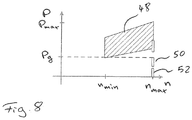
- the field 48 in FIG. 8 represents the range of normal operation.
- the normal operation 48 runs between a minimum rotational speed n min and a maximum rotational speed n max .
- the electrical power consumption P is between a lower limit P g and a maximum power consumption P max .
- the lower limit P g is a predetermined limit below which the detector unit 40 detects a gas accumulation. This is done at maximum speed n max . If a gas accumulation forms in the pump unit, this results in that the outlet pressure H or the differential pressure across the pump unit decreases.
- control unit 38 When control of the pressure H at the pressure port 20 is performed in the control unit 38 as described above, the control unit 38 will increase the rotational speed of the drive motor 4 to increase the pressure. When finally the maximum speed n max is reached, a comparison with the limit value P g for the electric power consumption P can take place in the prescribed manner at this speed. Alternatively, the speed could be increased to the value n max of the detector unit 40 via the control unit 38 at certain times, preferably at regular times. Further, it would also be possible to make a comparison with predetermined limits for the electric power consumption P at other predetermined speeds. Even at other speeds, the electrical power consumption P falls below an associated predetermined limit in an air accumulation.
- two operating states 50 and 52 can be distinguished at maximum rotational speed n max , the operating state 50 representing an operating state in which a gas accumulation is present in the pump stages 6 and the operating state 52 representing dry running.
- the electrical power consumption P is again lower, so that this can also be detected by the detector unit 40 and the control unit 38, for example, the electric drive motor 4 can be switched off.
- the controller 28 starts a venting function.
- the speed n of the drive motor 4 is first reduced by the control device 38 to such an extent that the pressure difference ⁇ P across the valve 26 decreases to such an extent that the valve 26 opens.
- the electric drive motor 4 has to be stopped by reducing the rotational speed n to zero. This condition is in FIG. 5 shown. In this state, there is only a small or no flow, and this can be compensated for a short time by the pressure accumulator 22, so that the output side of the pressure port 20, no complete pressure drop occurs.
- the rotational speed n of the drive motor 4 is very quickly increased again by the control device 28, preferably increased to the maximum rotational speed n max in less than three or less than two seconds.
- This condition is in FIG. 6 shown.
- the valve 26 remains open due to the inertia and the initially still small pressure difference .DELTA.P.
- the air accumulation initially distributed in the circulating flow 54. If now by the increasing pressure difference .DELTA.P, as in FIG.
- valve 26 closes again, the circulating flow 54 is suddenly stopped and it starts again the normal liquid flow 46 from the suction channel 16 through the four pump stages 6 in the pressure channel 18, in which the now distributed gas bubbles entrained and via the check valve 36 be flushed out the pressure port 20.
- the check valve 36 opens only when a sufficiently high pressure in the pressure channel 18 is established. Otherwise, the check valve 36 remains closed by the pressure in the subsequent to the pressure port 20 line and in the pressure accumulator 22. This is especially at the beginning of flow construction, which is based on FIG. 6 has been described, ie in the rapid increase in speed of the drive motor 4 of the case.
- the inventive early detection of gas accumulations in the pump unit prevents the centrifugal pump unit by the gas or air accumulation reaches such a state in which no sufficient pressure build-up and sufficient flow is no longer present. Rather, it can be ensured at an early stage that the gas accumulations are removed from the pump stages 6 by activating the venting function. It comes only to minor operational problems, since the speed of the drive motor 4 only has to be reduced for a short time or the drive motor 4 only has to be switched off for a short time. Due to the fast speed increase, it may lead to a short pressure peak, which, however, leads to only a small loss of comfort overall.
- venting function may be performed independently of the described detection of gas bubbles.
- an alternative detection of gas accumulation would be possible.
Landscapes
- Engineering & Computer Science (AREA)
- Mechanical Engineering (AREA)
- General Engineering & Computer Science (AREA)
- Life Sciences & Earth Sciences (AREA)
- Sustainable Development (AREA)
- Structures Of Non-Positive Displacement Pumps (AREA)
- Control Of Non-Positive-Displacement Pumps (AREA)
- Health & Medical Sciences (AREA)
- Hydrology & Water Resources (AREA)
- Public Health (AREA)
- Water Supply & Treatment (AREA)
Claims (13)
- Groupe motopompe centrifuge (2), comprenant au moins une roue mobile (12), un moteur d'entraînement électrique (4) entraînant la roue mobile (12), et un canal de retour (24) qui forme une liaison d'écoulement depuis le côté refoulement (18) de la roue mobile (12) jusqu'à son côté aspiration (16) et comporte une soupape (26) qui se ferme en fonction de la pression, destinée à la fermeture de ladite liaison d'écoulement,
caractérisé par
un dispositif de commande (28) pour le réglage de la vitesse (n) du moteur d'entraînement (4), qui est conçu pour comporter une fonction de purge d'air destinée à la purge d'air du groupe motopompe centrifuge (2) en service, selon laquelle, lors d'une première étape, la vitesse (n) du moteur d'entraînement (4) est réduite automatiquement par le dispositif de commande (28) après détection d'une accumulation d'air de façon à permettre l'ouverture de la soupape (26) dans le canal de retour (24), et ensuite, lors d'une seconde étape, la vitesse (n) est de nouveau augmentée avec une rapidité permettant de générer un fort courant avant la fermeture de la soupape (26), lequel permet de chasser l'accumulation d'air du groupe motopompe centrifuge (2). - Groupe motopompe centrifuge selon la revendication 1, caractérisé en ce que le dispositif de commande (28) est conçu de façon à augmenter la vitesse (n) à la vitesse maximale (nmax) lors de la seconde étape.
- Groupe motopompe centrifuge selon l'une des revendications précédentes, caractérisé en ce que le dispositif de commande (28) est conçu pour augmenter, lors de la seconde étape, la vitesse (n) à la vitesse maximale (nmax) en moins de trois, de préférence en moins de deux, secondes.
- Groupe motopompe centrifuge selon l'une des revendications précédentes, caractérisé en ce que le dispositif de commande (28) comporte une fonction de surveillance apte à détecter une accumulation d'air au fait qu'à une vitesse définie, en particulier à la vitesse maximale (nmax), la puissance électrique absorbée (P) passe sous une première valeur limite (Pg) prédéterminée.
- Groupe motopompe centrifuge selon la revendication 4, caractérisé en ce que le dispositif de commande (28) est conçu de telle sorte que la première valeur limite (Pg) de puissance électrique absorbée (P) se situe au-dessus d'une seconde valeur limite de puissance électrique absorbée (P) qui signale une marche à sec (52) du groupe motopompe centrifuge (2).
- Groupe motopompe centrifuge selon l'une des revendications précédentes, caractérisé en ce que, dans une position de fonctionnement prédéterminée, l'axe de rotation (x) du moteur d'entraînement (2) et de la roue mobile (12), au moins au nombre de une, s'étend horizontalement.
- Groupe motopompe centrifuge selon l'une des revendications précédentes, caractérisé en ce que le groupe motopompe centrifuge (2) est conçu à plusieurs étages et doté d'au moins deux roues mobiles (12), de préférence entraînées par un arbre commun (8).
- Groupe motopompe centrifuge selon la revendication 7, caractérisé en ce que le canal de retour (24) relie le côté refoulement de l'une des roues mobiles (12), et de préférence le côté refoulement (18) de la dernière roue mobile (12) dans le sens d'écoulement, avec le côté aspiration (16) de la première roue mobile.
- Installation d'alimentation en eau domestique pour le refoulement et/ou pour l'augmentation de pression dans une alimentation en eau, caractérisée en ce qu'elle comporte un groupe motopompe centrifuge (2) selon l'une des revendications précédentes.
- Procédé destiné à évacuer une accumulation d'air d'un groupe motopompe centrifuge (2) durant son fonctionnement, caractérisé par les étapes suivantes :
après détection d'une accumulation d'air, lors d'une première étape, abaissement de la vitesse (n) du groupe motopompe centrifuge (2) de façon à permettre l'ouverture d'une soupape (26) se fermant en fonction de la pression dans un canal de retour (24) entre le côté refoulement et le côté aspiration du groupe motopompe centrifuge (2), et ensuite, lors d'une seconde étape, augmentation rapide de la vitesse (n) du groupe motopompe centrifuge (2) de façon à générer un fort courant avant la fermeture de la soupape (26), lequel permet de chasser l'accumulation d'air du groupe motopompe centrifuge (2). - Procédé selon la revendication 10, caractérisé en ce que, lors de la seconde étape, la vitesse (n) du groupe motopompe centrifuge est augmentée à la vitesse maximale (nmax).
- Procédé selon l'une des revendications 10 ou 11, caractérisé en ce que la vitesse (n) est augmentée à la vitesse maximale (nmax) lors de la seconde étape en moins de trois, de préférence en moins de deux, secondes.
- Procédé selon l'une des revendications 10 à 12, caractérisé en ce qu'une accumulation d'air à évacuer est détectée dans le groupe motopompe centrifuge (2) au fait qu'à une vitesse définie, en particulier à la vitesse maximale (nmax), la puissance électrique absorbée (P) passe sous une valeur limite (Pg) prédéterminée.
Priority Applications (6)
| Application Number | Priority Date | Filing Date | Title |
|---|---|---|---|
| EP16188626.2A EP3293397B1 (fr) | 2016-09-13 | 2016-09-13 | Pompe centrifuge et procédé de purge d'air |
| AU2017213444A AU2017213444B2 (en) | 2016-09-13 | 2017-08-08 | Centrifugal pump |
| TW106130288A TWI661130B (zh) | 2016-09-13 | 2017-09-05 | 離心泵組及移除離心泵組中之積聚空氣的方法以及具有此離心泵組的住宅水務裝置 |
| US15/700,666 US10619640B2 (en) | 2016-09-13 | 2017-09-11 | Centrifugal pump assembly |
| RU2017131864A RU2681112C1 (ru) | 2016-09-13 | 2017-09-12 | Насосный агрегат |
| CN201710822421.6A CN107816437B (zh) | 2016-09-13 | 2017-09-13 | 泵机组 |
Applications Claiming Priority (1)
| Application Number | Priority Date | Filing Date | Title |
|---|---|---|---|
| EP16188626.2A EP3293397B1 (fr) | 2016-09-13 | 2016-09-13 | Pompe centrifuge et procédé de purge d'air |
Publications (2)
| Publication Number | Publication Date |
|---|---|
| EP3293397A1 EP3293397A1 (fr) | 2018-03-14 |
| EP3293397B1 true EP3293397B1 (fr) | 2018-10-24 |
Family
ID=56920656
Family Applications (1)
| Application Number | Title | Priority Date | Filing Date |
|---|---|---|---|
| EP16188626.2A Active EP3293397B1 (fr) | 2016-09-13 | 2016-09-13 | Pompe centrifuge et procédé de purge d'air |
Country Status (6)
| Country | Link |
|---|---|
| US (1) | US10619640B2 (fr) |
| EP (1) | EP3293397B1 (fr) |
| CN (1) | CN107816437B (fr) |
| AU (1) | AU2017213444B2 (fr) |
| RU (1) | RU2681112C1 (fr) |
| TW (1) | TWI661130B (fr) |
Cited By (1)
| Publication number | Priority date | Publication date | Assignee | Title |
|---|---|---|---|---|
| EP3929445A1 (fr) | 2020-06-22 | 2021-12-29 | Grundfos Holding A/S | Dispositif de pompe centrifuge |
Families Citing this family (7)
| Publication number | Priority date | Publication date | Assignee | Title |
|---|---|---|---|---|
| DE102018006877A1 (de) * | 2018-08-30 | 2020-03-05 | Fresenius Medical Care Deutschland Gmbh | Pumpvorrichtung zum Pumpen von Flüssigkeiten aufweisend eine Zentrifugalpumpe mit radial pumpendem Pumpenrad mit hohlem Zentrum |
| SG10201907366PA (en) * | 2018-09-17 | 2020-04-29 | Sulzer Management Ag | Multiphase pump |
| IT202000004882A1 (it) * | 2020-03-09 | 2021-09-09 | Dab Pumps Spa | Elettropompa con camicia perfezionata |
| CN112253471A (zh) * | 2020-10-26 | 2021-01-22 | 长沙中联泵业股份有限公司 | 一种高温高压多级泵 |
| DE102021132217A1 (de) * | 2021-12-07 | 2023-06-07 | Schwäbische Hüttenwerke Automotive GmbH | Fluidfördersystem mit lastabhängiger Drehzahlumkehr einer Rotationspumpe |
| DE102022001479A1 (de) | 2022-04-27 | 2023-11-02 | KSB SE & Co. KGaA | Kreiselpumpenanordnung |
| CN115750389A (zh) * | 2022-10-24 | 2023-03-07 | 利欧集团浙江泵业有限公司 | 一种吸程快速的水泵结构 |
Family Cites Families (10)
| Publication number | Priority date | Publication date | Assignee | Title |
|---|---|---|---|---|
| US2395657A (en) * | 1942-03-20 | 1946-02-26 | Curtis Pump Co | Automatic pressure control for booster pumps |
| SU364761A1 (ru) * | 1971-03-23 | 1972-12-28 | Зачистной насосный агрегат | |
| SU922319A1 (ru) * | 1980-03-04 | 1982-04-23 | Специальное Конструкторско-Технологическое Бюро Герметичных И Скважинных Насосов | Способ запуска центробежного насосного агрегата |
| FR2787526B1 (fr) * | 1998-12-21 | 2001-02-09 | Pompes Salmson Sa | Clapet d'amorcage pour pompe autoamorcante |
| KR100791044B1 (ko) * | 2007-06-21 | 2008-01-04 | 지효근 | 진공강자흡식펌프 |
| US8382446B2 (en) * | 2009-05-06 | 2013-02-26 | Baker Hughes Incorporated | Mini-surge cycling method for pumping liquid from a borehole to remove material in contact with the liquid |
| EP2505842B1 (fr) * | 2011-03-29 | 2019-12-25 | Grundfos Management a/s | Agrégat de pompe centrifuge à plusieurs étages |
| CN104470675B (zh) * | 2012-06-14 | 2017-06-16 | 流量控制有限责任公司 | 防止浸没泵气锁 |
| NO3018132T3 (fr) * | 2013-04-22 | 2018-05-12 | ||
| CN203441763U (zh) * | 2013-08-06 | 2014-02-19 | 利欧集团股份有限公司 | 多级离心泵之自吸装置 |
-
2016
- 2016-09-13 EP EP16188626.2A patent/EP3293397B1/fr active Active
-
2017
- 2017-08-08 AU AU2017213444A patent/AU2017213444B2/en active Active
- 2017-09-05 TW TW106130288A patent/TWI661130B/zh active
- 2017-09-11 US US15/700,666 patent/US10619640B2/en active Active
- 2017-09-12 RU RU2017131864A patent/RU2681112C1/ru active
- 2017-09-13 CN CN201710822421.6A patent/CN107816437B/zh active Active
Non-Patent Citations (1)
| Title |
|---|
| None * |
Cited By (2)
| Publication number | Priority date | Publication date | Assignee | Title |
|---|---|---|---|---|
| EP3929445A1 (fr) | 2020-06-22 | 2021-12-29 | Grundfos Holding A/S | Dispositif de pompe centrifuge |
| US11746795B2 (en) | 2020-06-22 | 2023-09-05 | Grundfos Holding A/S | Centrifugal pump device |
Also Published As
| Publication number | Publication date |
|---|---|
| AU2017213444A1 (en) | 2018-03-29 |
| EP3293397A1 (fr) | 2018-03-14 |
| RU2681112C1 (ru) | 2019-03-04 |
| TW201825787A (zh) | 2018-07-16 |
| TWI661130B (zh) | 2019-06-01 |
| CN107816437A (zh) | 2018-03-20 |
| US10619640B2 (en) | 2020-04-14 |
| US20180073509A1 (en) | 2018-03-15 |
| AU2017213444B2 (en) | 2019-01-17 |
| CN107816437B (zh) | 2019-10-18 |
Similar Documents
| Publication | Publication Date | Title |
|---|---|---|
| EP3293397B1 (fr) | Pompe centrifuge et procédé de purge d'air | |
| DE19781894B4 (de) | Selbstansaugende Kreiselpumpe | |
| EP2840264B1 (fr) | Système d'actionnement à sécurité intégrée | |
| EP2362102B1 (fr) | Agrégat de pompes de dosage | |
| EP1731684B1 (fr) | Procédé de levage d'eau usée et dispositif de levage d'eau usée | |
| EP2134971B1 (fr) | Système de pompe et procédé destiné à pomper des mélanges polyphasés | |
| DE102005043434A1 (de) | Einrichtung zur Leistungsanpassung einer Flüssigkeitsringpumpe | |
| EP2791511B1 (fr) | Pompe à vide à anneau liquide pourvue d'un réglage de cavitation | |
| EP2505842A1 (fr) | Agrégat de pompe centrifuge à plusieurs étages | |
| EP2655888B1 (fr) | Dispositif de pompage | |
| EP2589851A2 (fr) | Pompe de registre | |
| EP2681419B1 (fr) | Turbopropulseur avec un système d'alimentation en huile et procédé d'alimentation en huile d'un turbopropulseur | |
| DE69617421T2 (de) | Verfahren zur kontrolle einer kreiselpumpe und vakuumpumpenkombination sowie eine kreiselpumpe zur gastrennung | |
| DE112013001605T5 (de) | Kraftstoffzufuhrvorrichtung | |
| EP2161458B1 (fr) | Agencement d'alimentation d'un système hydraulique en liquide hydraulique | |
| EP2049800B1 (fr) | Pompe de circulation | |
| EP3507409B1 (fr) | Appareil d'entretien du linge doté d'une commande | |
| EP3519699B1 (fr) | Arrangement de pompage | |
| DE2313095C2 (de) | Pumpspeicheranlage | |
| EP2639369B1 (fr) | Dispositif anti-reflux pour installations d'eaux usées | |
| EP3839260B1 (fr) | Pompe centrifuge dotée d'une soupape automatique | |
| EP3446785A2 (fr) | Procédé de traitement d'un liquide chargé des copeaux | |
| DE102007051045B4 (de) | Anordnung mit Vakuumpumpe und Verfahren | |
| DE60311165T2 (de) | Kreiselpumpe für niedrige Flussraten mit verbesserter Ansaughöhe | |
| DE3032058C2 (de) | Mehrstufige Pumpen-Turbine |
Legal Events
| Date | Code | Title | Description |
|---|---|---|---|
| PUAI | Public reference made under article 153(3) epc to a published international application that has entered the european phase |
Free format text: ORIGINAL CODE: 0009012 |
|
| STAA | Information on the status of an ep patent application or granted ep patent |
Free format text: STATUS: REQUEST FOR EXAMINATION WAS MADE |
|
| 17P | Request for examination filed |
Effective date: 20170802 |
|
| AK | Designated contracting states |
Kind code of ref document: A1 Designated state(s): AL AT BE BG CH CY CZ DE DK EE ES FI FR GB GR HR HU IE IS IT LI LT LU LV MC MK MT NL NO PL PT RO RS SE SI SK SM TR |
|
| AX | Request for extension of the european patent |
Extension state: BA ME |
|
| GRAP | Despatch of communication of intention to grant a patent |
Free format text: ORIGINAL CODE: EPIDOSNIGR1 |
|
| STAA | Information on the status of an ep patent application or granted ep patent |
Free format text: STATUS: GRANT OF PATENT IS INTENDED |
|
| RIC1 | Information provided on ipc code assigned before grant |
Ipc: F04D 1/06 20060101ALI20180322BHEP Ipc: F04D 13/16 20060101ALI20180322BHEP Ipc: F04D 13/06 20060101ALI20180322BHEP Ipc: F04D 1/00 20060101AFI20180322BHEP Ipc: F04D 15/00 20060101ALI20180322BHEP Ipc: F04D 9/00 20060101ALI20180322BHEP |
|
| INTG | Intention to grant announced |
Effective date: 20180423 |
|
| GRAS | Grant fee paid |
Free format text: ORIGINAL CODE: EPIDOSNIGR3 |
|
| GRAJ | Information related to disapproval of communication of intention to grant by the applicant or resumption of examination proceedings by the epo deleted |
Free format text: ORIGINAL CODE: EPIDOSDIGR1 |
|
| GRAL | Information related to payment of fee for publishing/printing deleted |
Free format text: ORIGINAL CODE: EPIDOSDIGR3 |
|
| STAA | Information on the status of an ep patent application or granted ep patent |
Free format text: STATUS: REQUEST FOR EXAMINATION WAS MADE |
|
| GRAR | Information related to intention to grant a patent recorded |
Free format text: ORIGINAL CODE: EPIDOSNIGR71 |
|
| STAA | Information on the status of an ep patent application or granted ep patent |
Free format text: STATUS: GRANT OF PATENT IS INTENDED |
|
| INTC | Intention to grant announced (deleted) | ||
| INTG | Intention to grant announced |
Effective date: 20180807 |
|
| GRAA | (expected) grant |
Free format text: ORIGINAL CODE: 0009210 |
|
| STAA | Information on the status of an ep patent application or granted ep patent |
Free format text: STATUS: THE PATENT HAS BEEN GRANTED |
|
| AK | Designated contracting states |
Kind code of ref document: B1 Designated state(s): AL AT BE BG CH CY CZ DE DK EE ES FI FR GB GR HR HU IE IS IT LI LT LU LV MC MK MT NL NO PL PT RO RS SE SI SK SM TR |
|
| REG | Reference to a national code |
Ref country code: CH Ref legal event code: EP |
|
| REG | Reference to a national code |
Ref country code: IE Ref legal event code: FG4D Free format text: LANGUAGE OF EP DOCUMENT: GERMAN |
|
| REG | Reference to a national code |
Ref country code: AT Ref legal event code: REF Ref document number: 1056988 Country of ref document: AT Kind code of ref document: T Effective date: 20181115 |
|
| REG | Reference to a national code |
Ref country code: DE Ref legal event code: R096 Ref document number: 502016002309 Country of ref document: DE |
|
| REG | Reference to a national code |
Ref country code: NL Ref legal event code: MP Effective date: 20181024 |
|
| REG | Reference to a national code |
Ref country code: LT Ref legal event code: MG4D |
|
| PG25 | Lapsed in a contracting state [announced via postgrant information from national office to epo] |
Ref country code: NL Free format text: LAPSE BECAUSE OF FAILURE TO SUBMIT A TRANSLATION OF THE DESCRIPTION OR TO PAY THE FEE WITHIN THE PRESCRIBED TIME-LIMIT Effective date: 20181024 |
|
| PG25 | Lapsed in a contracting state [announced via postgrant information from national office to epo] |
Ref country code: IS Free format text: LAPSE BECAUSE OF FAILURE TO SUBMIT A TRANSLATION OF THE DESCRIPTION OR TO PAY THE FEE WITHIN THE PRESCRIBED TIME-LIMIT Effective date: 20190224 Ref country code: BG Free format text: LAPSE BECAUSE OF FAILURE TO SUBMIT A TRANSLATION OF THE DESCRIPTION OR TO PAY THE FEE WITHIN THE PRESCRIBED TIME-LIMIT Effective date: 20190124 Ref country code: PL Free format text: LAPSE BECAUSE OF FAILURE TO SUBMIT A TRANSLATION OF THE DESCRIPTION OR TO PAY THE FEE WITHIN THE PRESCRIBED TIME-LIMIT Effective date: 20181024 Ref country code: HR Free format text: LAPSE BECAUSE OF FAILURE TO SUBMIT A TRANSLATION OF THE DESCRIPTION OR TO PAY THE FEE WITHIN THE PRESCRIBED TIME-LIMIT Effective date: 20181024 Ref country code: NO Free format text: LAPSE BECAUSE OF FAILURE TO SUBMIT A TRANSLATION OF THE DESCRIPTION OR TO PAY THE FEE WITHIN THE PRESCRIBED TIME-LIMIT Effective date: 20190124 Ref country code: LT Free format text: LAPSE BECAUSE OF FAILURE TO SUBMIT A TRANSLATION OF THE DESCRIPTION OR TO PAY THE FEE WITHIN THE PRESCRIBED TIME-LIMIT Effective date: 20181024 Ref country code: ES Free format text: LAPSE BECAUSE OF FAILURE TO SUBMIT A TRANSLATION OF THE DESCRIPTION OR TO PAY THE FEE WITHIN THE PRESCRIBED TIME-LIMIT Effective date: 20181024 Ref country code: LV Free format text: LAPSE BECAUSE OF FAILURE TO SUBMIT A TRANSLATION OF THE DESCRIPTION OR TO PAY THE FEE WITHIN THE PRESCRIBED TIME-LIMIT Effective date: 20181024 Ref country code: FI Free format text: LAPSE BECAUSE OF FAILURE TO SUBMIT A TRANSLATION OF THE DESCRIPTION OR TO PAY THE FEE WITHIN THE PRESCRIBED TIME-LIMIT Effective date: 20181024 |
|
| PG25 | Lapsed in a contracting state [announced via postgrant information from national office to epo] |
Ref country code: AL Free format text: LAPSE BECAUSE OF FAILURE TO SUBMIT A TRANSLATION OF THE DESCRIPTION OR TO PAY THE FEE WITHIN THE PRESCRIBED TIME-LIMIT Effective date: 20181024 Ref country code: SE Free format text: LAPSE BECAUSE OF FAILURE TO SUBMIT A TRANSLATION OF THE DESCRIPTION OR TO PAY THE FEE WITHIN THE PRESCRIBED TIME-LIMIT Effective date: 20181024 Ref country code: RS Free format text: LAPSE BECAUSE OF FAILURE TO SUBMIT A TRANSLATION OF THE DESCRIPTION OR TO PAY THE FEE WITHIN THE PRESCRIBED TIME-LIMIT Effective date: 20181024 Ref country code: GR Free format text: LAPSE BECAUSE OF FAILURE TO SUBMIT A TRANSLATION OF THE DESCRIPTION OR TO PAY THE FEE WITHIN THE PRESCRIBED TIME-LIMIT Effective date: 20190125 Ref country code: PT Free format text: LAPSE BECAUSE OF FAILURE TO SUBMIT A TRANSLATION OF THE DESCRIPTION OR TO PAY THE FEE WITHIN THE PRESCRIBED TIME-LIMIT Effective date: 20190224 |
|
| REG | Reference to a national code |
Ref country code: DE Ref legal event code: R097 Ref document number: 502016002309 Country of ref document: DE |
|
| PG25 | Lapsed in a contracting state [announced via postgrant information from national office to epo] |
Ref country code: DK Free format text: LAPSE BECAUSE OF FAILURE TO SUBMIT A TRANSLATION OF THE DESCRIPTION OR TO PAY THE FEE WITHIN THE PRESCRIBED TIME-LIMIT Effective date: 20181024 Ref country code: CZ Free format text: LAPSE BECAUSE OF FAILURE TO SUBMIT A TRANSLATION OF THE DESCRIPTION OR TO PAY THE FEE WITHIN THE PRESCRIBED TIME-LIMIT Effective date: 20181024 |
|
| PG25 | Lapsed in a contracting state [announced via postgrant information from national office to epo] |
Ref country code: SK Free format text: LAPSE BECAUSE OF FAILURE TO SUBMIT A TRANSLATION OF THE DESCRIPTION OR TO PAY THE FEE WITHIN THE PRESCRIBED TIME-LIMIT Effective date: 20181024 Ref country code: RO Free format text: LAPSE BECAUSE OF FAILURE TO SUBMIT A TRANSLATION OF THE DESCRIPTION OR TO PAY THE FEE WITHIN THE PRESCRIBED TIME-LIMIT Effective date: 20181024 Ref country code: SM Free format text: LAPSE BECAUSE OF FAILURE TO SUBMIT A TRANSLATION OF THE DESCRIPTION OR TO PAY THE FEE WITHIN THE PRESCRIBED TIME-LIMIT Effective date: 20181024 Ref country code: EE Free format text: LAPSE BECAUSE OF FAILURE TO SUBMIT A TRANSLATION OF THE DESCRIPTION OR TO PAY THE FEE WITHIN THE PRESCRIBED TIME-LIMIT Effective date: 20181024 |
|
| PLBE | No opposition filed within time limit |
Free format text: ORIGINAL CODE: 0009261 |
|
| STAA | Information on the status of an ep patent application or granted ep patent |
Free format text: STATUS: NO OPPOSITION FILED WITHIN TIME LIMIT |
|
| 26N | No opposition filed |
Effective date: 20190725 |
|
| PG25 | Lapsed in a contracting state [announced via postgrant information from national office to epo] |
Ref country code: TR Free format text: LAPSE BECAUSE OF FAILURE TO SUBMIT A TRANSLATION OF THE DESCRIPTION OR TO PAY THE FEE WITHIN THE PRESCRIBED TIME-LIMIT Effective date: 20181024 |
|
| PG25 | Lapsed in a contracting state [announced via postgrant information from national office to epo] |
Ref country code: MC Free format text: LAPSE BECAUSE OF FAILURE TO SUBMIT A TRANSLATION OF THE DESCRIPTION OR TO PAY THE FEE WITHIN THE PRESCRIBED TIME-LIMIT Effective date: 20181024 |
|
| REG | Reference to a national code |
Ref country code: CH Ref legal event code: PL |
|
| PG25 | Lapsed in a contracting state [announced via postgrant information from national office to epo] |
Ref country code: IE Free format text: LAPSE BECAUSE OF NON-PAYMENT OF DUE FEES Effective date: 20190913 Ref country code: LI Free format text: LAPSE BECAUSE OF NON-PAYMENT OF DUE FEES Effective date: 20190930 Ref country code: LU Free format text: LAPSE BECAUSE OF NON-PAYMENT OF DUE FEES Effective date: 20190913 Ref country code: CH Free format text: LAPSE BECAUSE OF NON-PAYMENT OF DUE FEES Effective date: 20190930 |
|
| REG | Reference to a national code |
Ref country code: BE Ref legal event code: MM Effective date: 20190930 |
|
| PG25 | Lapsed in a contracting state [announced via postgrant information from national office to epo] |
Ref country code: BE Free format text: LAPSE BECAUSE OF NON-PAYMENT OF DUE FEES Effective date: 20190930 |
|
| PG25 | Lapsed in a contracting state [announced via postgrant information from national office to epo] |
Ref country code: CY Free format text: LAPSE BECAUSE OF FAILURE TO SUBMIT A TRANSLATION OF THE DESCRIPTION OR TO PAY THE FEE WITHIN THE PRESCRIBED TIME-LIMIT Effective date: 20181024 |
|
| PG25 | Lapsed in a contracting state [announced via postgrant information from national office to epo] |
Ref country code: MT Free format text: LAPSE BECAUSE OF FAILURE TO SUBMIT A TRANSLATION OF THE DESCRIPTION OR TO PAY THE FEE WITHIN THE PRESCRIBED TIME-LIMIT Effective date: 20181024 Ref country code: HU Free format text: LAPSE BECAUSE OF FAILURE TO SUBMIT A TRANSLATION OF THE DESCRIPTION OR TO PAY THE FEE WITHIN THE PRESCRIBED TIME-LIMIT; INVALID AB INITIO Effective date: 20160913 |
|
| PG25 | Lapsed in a contracting state [announced via postgrant information from national office to epo] |
Ref country code: SI Free format text: LAPSE BECAUSE OF FAILURE TO SUBMIT A TRANSLATION OF THE DESCRIPTION OR TO PAY THE FEE WITHIN THE PRESCRIBED TIME-LIMIT Effective date: 20181024 |
|
| PG25 | Lapsed in a contracting state [announced via postgrant information from national office to epo] |
Ref country code: MK Free format text: LAPSE BECAUSE OF FAILURE TO SUBMIT A TRANSLATION OF THE DESCRIPTION OR TO PAY THE FEE WITHIN THE PRESCRIBED TIME-LIMIT Effective date: 20181024 |
|
| REG | Reference to a national code |
Ref country code: DE Ref legal event code: R082 Ref document number: 502016002309 Country of ref document: DE |
|
| REG | Reference to a national code |
Ref country code: AT Ref legal event code: MM01 Ref document number: 1056988 Country of ref document: AT Kind code of ref document: T Effective date: 20210913 |
|
| PG25 | Lapsed in a contracting state [announced via postgrant information from national office to epo] |
Ref country code: AT Free format text: LAPSE BECAUSE OF NON-PAYMENT OF DUE FEES Effective date: 20210913 |
|
| PGFP | Annual fee paid to national office [announced via postgrant information from national office to epo] |
Ref country code: GB Payment date: 20230920 Year of fee payment: 8 |
|
| PGFP | Annual fee paid to national office [announced via postgrant information from national office to epo] |
Ref country code: FR Payment date: 20230928 Year of fee payment: 8 Ref country code: DE Payment date: 20230920 Year of fee payment: 8 |
|
| PGFP | Annual fee paid to national office [announced via postgrant information from national office to epo] |
Ref country code: IT Payment date: 20230927 Year of fee payment: 8 |