EP3844040B1 - Procédé permettant de faire fonctionner un véhicule à moteur et véhicule à moteur correspondant - Google Patents
Procédé permettant de faire fonctionner un véhicule à moteur et véhicule à moteur correspondant Download PDFInfo
- Publication number
- EP3844040B1 EP3844040B1 EP19742144.9A EP19742144A EP3844040B1 EP 3844040 B1 EP3844040 B1 EP 3844040B1 EP 19742144 A EP19742144 A EP 19742144A EP 3844040 B1 EP3844040 B1 EP 3844040B1
- Authority
- EP
- European Patent Office
- Prior art keywords
- torque
- wheel
- rotational speed
- target
- actual
- Prior art date
- Legal status (The legal status is an assumption and is not a legal conclusion. Google has not performed a legal analysis and makes no representation as to the accuracy of the status listed.)
- Active
Links
- 238000000034 method Methods 0.000 title claims description 39
- 230000001133 acceleration Effects 0.000 claims description 18
- 230000009467 reduction Effects 0.000 claims description 9
- 230000001276 controlling effect Effects 0.000 claims description 8
- 230000001105 regulatory effect Effects 0.000 claims description 6
- 230000033228 biological regulation Effects 0.000 claims description 4
- 230000008569 process Effects 0.000 description 11
- 230000000694 effects Effects 0.000 description 5
- 230000008901 benefit Effects 0.000 description 3
- 238000009826 distribution Methods 0.000 description 3
- 238000001556 precipitation Methods 0.000 description 3
- 230000008859 change Effects 0.000 description 2
- 230000001360 synchronised effect Effects 0.000 description 2
- 230000006978 adaptation Effects 0.000 description 1
- 239000000872 buffer Substances 0.000 description 1
- 230000008878 coupling Effects 0.000 description 1
- 238000010168 coupling process Methods 0.000 description 1
- 238000005859 coupling reaction Methods 0.000 description 1
- 230000007423 decrease Effects 0.000 description 1
- 230000007613 environmental effect Effects 0.000 description 1
- 238000009987 spinning Methods 0.000 description 1
Images
Classifications
-
- B—PERFORMING OPERATIONS; TRANSPORTING
- B60—VEHICLES IN GENERAL
- B60T—VEHICLE BRAKE CONTROL SYSTEMS OR PARTS THEREOF; BRAKE CONTROL SYSTEMS OR PARTS THEREOF, IN GENERAL; ARRANGEMENT OF BRAKING ELEMENTS ON VEHICLES IN GENERAL; PORTABLE DEVICES FOR PREVENTING UNWANTED MOVEMENT OF VEHICLES; VEHICLE MODIFICATIONS TO FACILITATE COOLING OF BRAKES
- B60T8/00—Arrangements for adjusting wheel-braking force to meet varying vehicular or ground-surface conditions, e.g. limiting or varying distribution of braking force
- B60T8/17—Using electrical or electronic regulation means to control braking
- B60T8/175—Brake regulation specially adapted to prevent excessive wheel spin during vehicle acceleration, e.g. for traction control
-
- B—PERFORMING OPERATIONS; TRANSPORTING
- B60—VEHICLES IN GENERAL
- B60T—VEHICLE BRAKE CONTROL SYSTEMS OR PARTS THEREOF; BRAKE CONTROL SYSTEMS OR PARTS THEREOF, IN GENERAL; ARRANGEMENT OF BRAKING ELEMENTS ON VEHICLES IN GENERAL; PORTABLE DEVICES FOR PREVENTING UNWANTED MOVEMENT OF VEHICLES; VEHICLE MODIFICATIONS TO FACILITATE COOLING OF BRAKES
- B60T8/00—Arrangements for adjusting wheel-braking force to meet varying vehicular or ground-surface conditions, e.g. limiting or varying distribution of braking force
- B60T8/17—Using electrical or electronic regulation means to control braking
- B60T8/176—Brake regulation specially adapted to prevent excessive wheel slip during vehicle deceleration, e.g. ABS
- B60T8/1766—Proportioning of brake forces according to vehicle axle loads, e.g. front to rear of vehicle
-
- B—PERFORMING OPERATIONS; TRANSPORTING
- B60—VEHICLES IN GENERAL
- B60T—VEHICLE BRAKE CONTROL SYSTEMS OR PARTS THEREOF; BRAKE CONTROL SYSTEMS OR PARTS THEREOF, IN GENERAL; ARRANGEMENT OF BRAKING ELEMENTS ON VEHICLES IN GENERAL; PORTABLE DEVICES FOR PREVENTING UNWANTED MOVEMENT OF VEHICLES; VEHICLE MODIFICATIONS TO FACILITATE COOLING OF BRAKES
- B60T2201/00—Particular use of vehicle brake systems; Special systems using also the brakes; Special software modules within the brake system controller
- B60T2201/16—Curve braking control, e.g. turn control within ABS control algorithm
-
- B—PERFORMING OPERATIONS; TRANSPORTING
- B60—VEHICLES IN GENERAL
- B60T—VEHICLE BRAKE CONTROL SYSTEMS OR PARTS THEREOF; BRAKE CONTROL SYSTEMS OR PARTS THEREOF, IN GENERAL; ARRANGEMENT OF BRAKING ELEMENTS ON VEHICLES IN GENERAL; PORTABLE DEVICES FOR PREVENTING UNWANTED MOVEMENT OF VEHICLES; VEHICLE MODIFICATIONS TO FACILITATE COOLING OF BRAKES
- B60T2270/00—Further aspects of brake control systems not otherwise provided for
- B60T2270/60—Regenerative braking
- B60T2270/602—ABS features related thereto
-
- B—PERFORMING OPERATIONS; TRANSPORTING
- B60—VEHICLES IN GENERAL
- B60T—VEHICLE BRAKE CONTROL SYSTEMS OR PARTS THEREOF; BRAKE CONTROL SYSTEMS OR PARTS THEREOF, IN GENERAL; ARRANGEMENT OF BRAKING ELEMENTS ON VEHICLES IN GENERAL; PORTABLE DEVICES FOR PREVENTING UNWANTED MOVEMENT OF VEHICLES; VEHICLE MODIFICATIONS TO FACILITATE COOLING OF BRAKES
- B60T2270/00—Further aspects of brake control systems not otherwise provided for
- B60T2270/60—Regenerative braking
- B60T2270/604—Merging friction therewith; Adjusting their repartition
Definitions
- the invention relates to a method for operating a motor vehicle, with a drive device that has at least one electric traction machine, a target torque being set on a control unit of the traction machine in order to provide a torque at a wheel of the motor vehicle, and a torque control for setting one of the Traction machine generated actual torque is performed.
- the invention also relates to a motor vehicle.
- the WO 2013 041 311 A1 describes a control device that controls an electric machine to generate a braking torque or an acceleration torque in order to better keep the wheel at the optimum slip point.
- the object of the invention is to propose a method for operating a motor vehicle, which has advantages over known methods, in particular in a simple manner during a braking process and/or an acceleration process of the motor vehicle enables strong acceleration or deceleration of the motor vehicle, with a stable Driving behavior of the motor vehicle is ensured.
- a speed setpoint range is additionally set on the control unit and if the actual speed of the wheel is in the speed setpoint range, the actual torque is regulated to the setpoint torque in the course of torque control and if the actual speed is outside the speed setpoint range, the torque control is carried out in such a way that the actual speed moves in the direction of the Speed setpoint range changed.
- the motor vehicle has the drive device, which is used to drive the motor vehicle, ie to provide a torque aimed at driving the motor vehicle.
- the drive device has the electric traction machine, which is coupled or at least can be coupled to the wheel of the motor vehicle.
- the drive device and therefore the traction machine are controlled accordingly.
- the target torque is set at the control unit of the traction machine.
- the target torque can, for example, correspond to a default torque, which in turn is specified by a driver of the motor vehicle and/or a driver assistance device of the motor vehicle.
- the control unit is provided and designed to carry out the torque control.
- the torque regulation includes the regulating setting of the actual torque provided by the traction machine for the wheel. At least temporarily, the actual torque generated by the traction machine is set to the target torque as part of the torque control. In this respect, the actual torque is used as the manipulated variable, whereas the difference between the actual torque and the setpoint torque, for example, is used as the controlled variable.
- the speed setpoint range is set on the control unit, which is used to carry out the torque control, in addition to the setpoint torque.
- the speed range describes the speed range in which the actual speed of the wheel is ideally located.
- the target speed range can be chosen to achieve different benefits based on different boundary conditions. In any case, however, it is intended to check whether the actual speed is in the desired speed range. If this is the case, the actual torque provided by the traction machine is adjusted to the target torque as part of the speed control, ie it is adjusted to the target torque in a controlling manner.
- the setpoint torque can be disregarded in the torque control or at least only given subordinate consideration.
- speed control is now carried out in such a way that the actual speed changes in the direction of the speed setpoint range.
- This speed control is preferably carried out until the actual speed is in the speed setpoint range.
- the actual torque can then be regulated again in the direction of the target torque, namely preferably until the actual speed is again outside the target speed range.
- the actual torque is kept as close as possible to the setpoint torque or at least changed in the direction of the setpoint torque, provided the actual speed allows this.
- acceleration is understood to mean both positive acceleration and negative acceleration.
- positive acceleration the speed of the motor vehicle increases in its main driving direction, ie forwards.
- negative acceleration the speed in the main driving direction decreases.
- negative acceleration can also be referred to as deceleration or braking of the motor vehicle.
- the additional specification of the speed setpoint range is useful, for example, when the motor vehicle brakes.
- the maximum torque that can be applied to the wheel is determined by a slip curve, which reflects the relationship between the torque that can be applied and the slip.
- the relationship between wheel slip and the maximum torque that can be delivered, which is reflected in the slip curve, applies to both positive and negative torques.
- the torque that can be deducted usually increases, starting from zero, with increasing slip, in particular linearly. It then increases up to the maximum torque that can be deducted, usually not linearly, and then drops rapidly as the slip continues to increase. A slip above the slip that occurs at the maximum torque that can be deducted should therefore be avoided because the torque that can be deducted falls sharply as the slip increases.
- a type of anti-lock braking control is now to be carried out as part of the torque control by the procedure described, with the setting of the target torque and the target speed range on the control device.
- the traction machine is used to impress a braking torque on the wheel, this braking torque preferably corresponding to the maximum torque that can be deducted.
- the torque corresponding to the maximum torque that can be deposited would only have to be applied to the wheel using the traction machine. In practice, however, this is usually not possible because, on the one hand, the slip curve is not exactly known and, on the other hand, it changes constantly changes. Furthermore, the torque accuracy of the traction machine can vary widely.
- the method described can be used for optimal torque distribution between a plurality of wheel axles of the motor vehicle and/or between a plurality of wheels on the same wheel axle.
- the wheel is assigned, for example, to a first wheel axle and a further wheel of the motor vehicle is assigned to a second wheel axle which is different from the first wheel axle, the wheel track of the further wheel corresponding to the wheel track of the wheel.
- the same procedure is carried out for the other wheel as for the wheel.
- provision is preferably made for a target torque to be set on the control device or a further control unit of a further traction machine assigned to the further wheel and by means of the control unit in order to provide a torque on the further wheel or the further control unit carries out a torque regulation for setting an actual torque generated by the further traction machine.
- a speed setpoint range is additionally set on the control unit or the additional control unit and if the actual speed of the other wheel is in the speed setpoint range, the actual torque is regulated to the setpoint torque as part of the torque control and if the actual speed is outside the speed setpoint range, the torque control is carried out in such a way that the actual speed changes in the direction of the Speed setpoint range changed.
- the target torque and/or the target speed range can be chosen to be different or identical for the wheel and the additional wheel.
- the invention provides that the speed setpoint range is limited downwards by a lower speed limit and upwards by an upper speed limit, which are determined based on a driving speed of the motor vehicle and an optimum slip of the wheel.
- the speed setpoint range is limited by the lower speed limit and the upper speed limit.
- Both the lower speed limit and the upper speed limit are determined (in each case) based on the driving speed and the optimal slip of the wheel.
- the driving speed is measured and/or estimated using at least one sensor, for example.
- the slip optimum of the wheel is preferably estimated, in particular also using a suitable sensor.
- the optimum slip is determined from the slip curve, which in turn is determined by correspondingly operating the motor vehicle.
- a torque present at a rear axle of the motor vehicle is selected to be different from a torque present at a front axle of the motor vehicle.
- Different values are preferably used for the torques applied to the front axle and the rear axle and the respective Wheel speeds measured on the front axle and the rear axle.
- the slip or the slip curve can then be determined from the speeds.
- the slip optimum corresponds to the slip at the maximum deductible torque or is present at this.
- the lower speed limit and the upper speed limit are preferably different from one another, in particular the upper speed limit is greater than the lower speed limit.
- the lower speed limit is determined from the driving speed and wheel slip, which is a specific amount above the optimum slip
- the upper speed limit is determined from the driving speed and a slip, which is a specific value below the optimum slip.
- the specific value is preferably the same for the lower speed limit and the upper speed limit, so that the slip for the lower speed limit and the slip for the upper speed limit are selected symmetrically with respect to the optimum slip.
- the lower speed limit is selected according to a negative optimum slip and the upper speed limit is selected according to a positive optimum slip.
- the lower speed limit and the upper speed limit preferably lie between the negative optimum slip and the positive optimum slip (these values are included in each case).
- a first part of a braking torque applied to the wheel is generated by means of a service brake and a second part by means of the traction machine, with the first part being selected to be smaller than one in the Slip optimum torque that can be deducted via the wheel.
- the braking torque which is to be applied to the wheel is therefore divided into the two parts, namely the first part and the second part.
- the first part is provided by the service brake, while the second part is generated by the traction machine.
- the torque or braking torque that can be set on the wheel by means of the service brake can usually only be adjusted more slowly than the torque that can be set by means of the traction machine. For this reason, it is now planned to do the first part in this way choose that it is smaller than the maximum torque that can be deducted, i.e. the torque that can be deducted via the wheel in the slip optimum. In this way, it is ensured that the first part of the braking torque alone does not cause the maximum torque that can be delivered to be exceeded.
- the first part of the braking torque is at most 90%, at most 80%, at most 75%, at most 70%, at most 60% or at most 50% of the maximum torque that can be delivered.
- the remainder of the requested braking torque is provided in the form of the second part by the traction machine and can be adjusted quickly.
- the second part is selected in such a way that the total braking torque corresponds to the maximum torque that can be deducted. In this way, a particularly effective braking operation of the motor vehicle is implemented.
- a further embodiment of the invention provides that during the braking process the second part of the braking torque is built up faster than the first part, with the second part of the braking torque being increased until the sum of the first part and the second part corresponds to a setpoint braking torque, and wherein after the setpoint braking torque has been reached by the sum of the first part and the second part, the first part is increased further in the sum corresponding to the setpoint braking torque.
- the braking torque on the wheel can usually be built up more quickly by means of the traction machine than by means of the service brake.
- the second part of the braking torque is built up faster than the first part.
- the first part of the braking torque is further increased by the sum of the first part and the second part even after the setpoint braking torque has been reached, namely until it has reached its intended maximum.
- the first part and the second part of the braking torque are increased independently of one another.
- the first part should be increased further be, but the sum of the two parts should continue to correspond to the target braking torque.
- the first part and the second part of the braking torque are always tracked. This tracking takes place in such a way that it is always possible to reliably provide the setpoint braking torque.
- the first part always corresponds to at least 50%, at least 60%, at least 70% or at least 75% of the setpoint braking torque. If the first part falls below this value, it is increased until it has reached it. Accordingly, the second part is changed in such a way that the sum of the two parts continues to correspond to the setpoint braking torque.
- the second part can be selected in such a way that it counteracts this behavior. For example, the second part is rapidly ramped down to zero. Alternatively, the second part can even have a different sign than the first part, so that the traction machine counteracts the service brake in order to prevent or stop the wheel from locking. Additionally or alternatively, it can be provided that an anti-lock braking process is carried out for the first part of the braking torque, ie the service brake is opened periodically and set again to effect the first part of the braking torque.
- a particularly preferred further embodiment of the invention provides that during an acceleration process of the motor vehicle when the actual speed of the wheel exceeds the upper speed limit, the actual torque is reduced until the actual speed is less than or equal to the upper speed limit, and the reduced actual torque or the difference between the target torque and the reduced actual torque is transmitted to a further control unit after or during the reduction.
- the actual rotational speed of the wheel exceeds the upper rotational speed limit, it is concluded that the wheel is spinning or that the wheel is subjected to a torque that is greater than the maximum torque that can be deducted.
- the actual speed of the wheel should be reduced until it is less than or equal to the upper speed limit.
- the reduced actual torque or the amount by which the actual torque was reduced starting from the target torque is already transmitted to the further control unit during the reduction or only after the reduction has been completed.
- Such a procedure is provided in particular if, in addition to the traction machine, by means of which the wheel of the motor vehicle can be driven, there is a further traction machine, by means of which a further wheel of the motor vehicle can be driven.
- the wheel and the other wheel are preferably assigned to different wheel axles of the motor vehicle, for example the wheel to a rear axle or a front axle of the motor vehicle and the other wheel to the other wheel axle, the wheel and the other wheel being assigned to the same wheel track.
- the further control device is used, for example, to determine a target torque for the traction machine and the further traction machine and to set it there.
- a preferred development of the invention provides for the wheel to be assigned to a first wheel axle and another wheel of the motor vehicle to be assigned to a second wheel axle that is different from the first wheel axle, with a further target torque being assigned to a further control unit of a further traction machine in order to provide a torque on the further wheel is set and a torque control for setting a further actual torque generated by the further traction machine is carried out by means of the further control unit, the difference between the target torque and the reduced actual torque being added to the further target torque.
- the explanations in the context of this description for the traction machine, the control unit and the wheel can also be used.
- the additional traction machine, the additional control unit and the additional wheel are therefore preferably configured analogously to the traction machine, the control unit and the wheel, with the difference that the additional wheel is assigned to a different wheel axle than the wheel.
- the target torque is set on the control device and the further target torque is set on the further control device.
- the target torque and the further target torque are, for example, from a central control unit determined from a default total torque and transmitted to the control unit and the other control unit.
- the torque by which the actual torque of the traction machine was reduced starting from the target torque should also be applied to the further wheel by the further traction machine via the further target torque set on it .
- the torque on the other wheel axle is increased by the amount of the reduction.
- this preferably applies in both directions, so that a torque reduction on the first wheel axle is compensated for by an increase in torque on the second wheel axle and a torque reduction on the second wheel axle by an increase in torque on the first wheel axle.
- the speed of the wheel is preferably understood to mean a speed of the first wheel axle and/or an average speed of wheels present on the first wheel axle.
- the speed of the other wheel is a speed of the second wheel axle and/or an average speed of other wheels present on the second wheel axle.
- a preferred further embodiment of the invention provides that a central control unit divides a default total torque into a first default torque and a second default torque, with the target torque being set equal to the first default torque and the other target torque being set equal to the second default torque and then the target torque on the control unit and the other Target torque can be set on the further control device, the difference between the target torque and the reduced actual torque being added to the further target torque before the setting.
- the default total torque is, for example, a torque specified by the driver of the motor vehicle and/or a driver assistance device of the motor vehicle. This is divided into the first default torque and the second default torque, so that the sum of the two default torques corresponds to the default total torque. This division takes place, for example, according to a predetermined division, according to which a specific portion of the default total torque should be applied to a rear axle and the remainder to the front axle.
- the setpoint torque is now set equal to the first default torque and the further setpoint torque is set equal to the second default torque.
- the setpoint torque and/or the further setpoint torque is then corrected. In particular, the difference between the target torque and the reduced actual torque is added to the further target torque. If the actual torque is also reduced for the additional traction machine or the additional wheel, the difference between the additional desired torque and the additional reduced actual torque is added to the desired torque.
- the target torque is then set on the control unit and the further target torque is set on the further control unit.
- the splitting of the default total torque into the first default torque and the second default torque can take place, for example, as part of a pilot control, so that ideally the control unit and the other control unit are set to target torques that correspond to the maximum torque that can be delivered to the corresponding wheel.
- at least one environmental condition can be used for pre-control, for example an outside temperature, an incline of a surface on which the motor vehicle is being moved, a precipitation parameter and/or air humidity.
- the precipitation parameter corresponds, for example, to a switching state of a windshield wiper of the motor vehicle and to this extent indicates whether precipitation is present or not. In any case, it can be provided at a Speed limitation of the traction machine and / or the other traction machine to cache the current actual torque as the maximum deductible torque. This maximum torque that can be deducted, which is available for the traction machine and/or the additional traction machine (in each case), can also be used for pilot control in order to ideally prevent the need for speed limitation.
- a preferred embodiment of the invention provides that the wheel and the other wheel are assigned to the same wheel axles and different wheel tracks or assigned to different wheel axles and the same wheel track, with a maximum differential speed and a minimum differential speed for a speed difference between the speed of the wheel and the speed of the further wheel are determined and the upper speed limit for the wheel is determined from the actual speed of the further wheel and the maximum differential speed and the upper speed limit for the further wheel is determined from the actual speed of the wheel and the minimum differential speed.
- maintaining a differential speed is described.
- the wheels are no longer assigned to different wheel axles, but rather to the same wheel axle, but with different wheel tracks.
- the wheels are on different sides of the motor vehicle.
- the wheel is a left wheel and the other wheel is a right wheel.
- the wheels are assigned to different wheel axles. In this case, the wheels are assigned to the same wheel track.
- the motor vehicle can have a wheel-specific drive or a single-wheel drive, with the wheel being able to be driven by the traction machine and the other wheel being able to be driven by the other traction machine. This means that there is no direct mechanical coupling between the wheel and the other wheel, but only indirectly via the ground on which they are located.
- a differential speed band is defined, which is limited at the bottom by the minimum differential speed and at the top by the maximum differential speed.
- the differential speed maximum represents a maximum permissible value for the speed difference
- the differential speed minimum represents a minimum permissible value for the speed difference, the speed difference describing the difference between the speed of the wheel and the speed of the other wheel.
- the upper speed limit already mentioned above is now determined for the wheel from the actual speed of the other wheel and the maximum differential speed and the upper speed limit for the other wheel from the actual speed of the wheel and the minimum differential speed.
- the upper speed limit for the wheel results from the actual speed of the other wheel plus the maximum differential speed and the upper speed limit for the other wheel from the actual speed of the wheel minus the minimum differential speed, with the maximum differential speed being positive and the minimum differential speed being negative.
- the behavior is also for the wheel-individually driven motor vehicle a transverse lock between the wheels with high accuracy, so that a high level of driving comfort and/or good traction or good driving dynamics is ensured, in particular for the configuration according to which the wheels are assigned to different wheel tracks and are present on the same or on different wheel axles.
- the differential speed minimum and the differential speed maximum are preferably different from each other, in particular the differential speed maximum is greater than the differential speed minimum.
- the differential speed maximum and the differential speed minimum can be determined from the driving speed of the motor vehicle.
- a steering angle of the motor vehicle can be used to determine the maximum differential rotational speed and the minimum differential rotational speed.
- an upper differential torque limit is additionally determined and the torque control for the wheel and for the other wheel is carried out in such a way that the difference between the actual torque present at the wheel and that at the other wheel applied further actual torque is less than or equal to the differential torque upper limit. If only the upper speed limits for the wheel and the other wheel are specified, it could be the case that the entire default total torque is to be transmitted via the wheel or the other wheel or the difference between the setpoint torques set at the wheel and the other wheel or the at these present actual torques cause an undesirably large yaw torque on the motor vehicle. In order to avoid this, the difference between the actual torques is limited in addition to the speed, namely to the differential torque upper limit.
- the setpoint torque set for the other wheel is correspondingly increased. If no further shifting of the torque is possible, for example because the drive of the other wheel in each case is already providing an actual torque which corresponds to a maximum adjustable torque or the nominal torque of the respective traction machine, then it is provided, for example, to increase the permissible differential speed, namely by means of a corresponding Adaptation of the differential speed maximum and/or the differential speed minimum until the torque that can be deducted via the wheel and the other wheel, ie the sum of the two actual torques, corresponds to the default total torque.
- the torque for the wheel is limited, it is checked whether a higher torque can be sold via the other wheel. If this is the case, the setpoint torque set for the other wheel is increased. If, on the other hand, the condition is not met, then the differential speed minimum is increased. If, on the other hand, the speed control for the other wheel is effective, it is checked whether a higher torque can be delivered via the wheel. If this is the case, the setpoint torque set for the wheel is increased. If the condition does not apply, the differential speed maximum is increased.
- any difference between the actual torque applied to the wheel and the additional actual torque applied to the other wheel is preferably reduced by appropriately setting the target torques, namely in particular until the difference is equal to zero.
- the differential speed maximum and the differential speed minimum are reset to their original values if they were previously changed or adjusted.
- limiting the difference between the actual torques to the differential torque upper limit has the highest priority, followed by maintaining the speed range, which is defined by the differential speed maximum and the differential speed minimum is limited.
- Limiting the speed of the individual wheels or the individual traction machines has lower priority, and setting the actual torque to the specified setpoint torque has the lowest priority. While the motor vehicle is cornering, provision can be made for torque to be shifted in a targeted manner to the outside of the curve so that the handling of the motor vehicle is improved.
- an absolute speed limitation and compliance with a differential speed are mentioned.
- the absolute speed limitation is carried out, for example, for wheels on different wheel axles, namely in such a way that torque is shifted from the wheel to the other wheel or vice versa.
- the wheels are assigned to the same wheel axle and the torque is nevertheless shifted between them.
- the differential speed can be maintained between the wheels on the same wheel axle or wheels on different wheel axles.
- the principles of absolute speed limitation and compliance with the differential speed can be applied separately, but can also be combined with one another as desired. This applies in particular to wheels on the same wheel axle and different lanes on the one hand and for wheels on different wheel axles and the same lane on the other hand.
- the differential speed limitation can be implemented so that when the differential speed between the wheels of the wheel axles is very low, the torque is quickly redistributed so that the speeds of both axles run up as synchronously as possible.
- the absolute speed limitation it can be provided that there is an absolute maximum speed, because the axles should not rev up indefinitely in order to keep the wheels in the optimum slip range. A combination of these measures has the effect that the wheels of the wheel axles with as synchronous a speed as possible up to the optimum traction turn slip up. Then the absolute speed limitation takes effect and the axles stop turning up.
- the differential speed limit can be implemented so that when the differential speed between the wheels is very low, the torque is quickly redistributed so that the speeds of both wheels run up as synchronously as possible.
- the curve radius can also be included in the specified differential speed, so that distortion is prevented. This achieves very good driving dynamics.
- a differential speed is imposed on the wheel and the other wheel, so that they can be operated in a targeted manner in different slip ranges.
- an absolute maximum speed is specified because the wheels are not supposed to spin up infinitely in order to keep the wheels in the optimum slip range.
- the invention also relates to a motor vehicle, in particular for carrying out the method according to the statements made within the scope of this description, with a drive device which has at least one electric traction machine, with a setpoint torque being adjustable on a control unit of the traction machine in order to provide a torque on a wheel of the motor vehicle and a torque control for setting an actual torque generated by the traction machine can be carried out by means of the control unit.
- the motor vehicle is designed to additionally set a target speed range on the control unit and to regulate the actual torque to the target torque in the course of torque control when the actual speed of the wheel is in the target speed range and if the actual speed is outside the speed target range, to carry out the torque control in such a way that the actual speed changes in the direction of the speed target range.
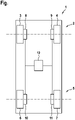
- the figure shows a schematic representation of a motor vehicle 1 which has a first wheel axle 2 with wheels 3 and 4 and a second wheel axle 5 with wheels 6 and 7 .
- the first wheel axle 2 is, for example, a front axle and the second wheel axle 5 is a rear axle of the motor vehicle 1.
- the wheels 3 and 4 are front wheels and the wheels 6 and 7 are rear wheels of the motor vehicle 1.
- the wheels 3 and 6 are a first lane and the wheels 4 and 7 assigned to a second lane. This means that the wheels 3 and 6 are arranged on a first side and the wheels 4 and 7 are arranged on a second side of the motor vehicle 1 in the lateral direction.
- the wheels 3, 4, 6 and 7 can be driven by means of traction machines 8, 9, 10 and 11, with each of the traction machines 8, 9, 10 and 11 being assigned a control unit which is not shown here.
- the control unit of each of the traction machines 8, 9, 10 and 11 is connected to a central control unit 12.
- a target torque is set on the control unit of the respective traction machine 8, 9, 10 and 11 and a torque control for setting one of the traction machines 8, 9, 10 and 11 to perform the actual torque generated.
- a target speed range is set on the control unit and if the actual speed of wheel 3, 4, 6 or 7 is in the target speed range, the actual torque is regulated to the target torque in the course of torque control.
- the torque control is carried out in such a way that the actual speed changes in the direction of the speed setpoint range.
- the wheel is one of the wheels 3, 4 of the first wheel axle 2 and the other wheel is one of the wheels 6 and 7 of the second wheel axle 5 or vice versa.
- the wheel is one of wheels 8 and 10 and the other wheel is one of wheels 9 and 11, with the wheel and the other wheel being assigned to the same wheel axle, for example the first wheel axle 2 or the second wheel axle 5 .
Landscapes
- Engineering & Computer Science (AREA)
- Transportation (AREA)
- Mechanical Engineering (AREA)
- Chemical & Material Sciences (AREA)
- Combustion & Propulsion (AREA)
- Electric Propulsion And Braking For Vehicles (AREA)
Claims (9)
- Procédé permettant de faire fonctionner un véhicule à moteur (1), au moyen d'un appareil de propulsion qui présente au moins une machine de traction électrique (8, 9, 10, 11), dans lequel, pour fournir un couple à une roue (3, 4, 6, 7) du véhicule à moteur (1), un couple cible est réglé sur un dispositif de commande de la machine de traction (8, 9, 10, 11) et au moyen du dispositif de commande de couple, une régulation de couple est effectuée pour régler un couple réel généré par la machine de traction (8, 9, 10, 11), dans lequel une plage cible de régimes est également réglée sur le dispositif de commande, et lorsque le régime réel de la roue (3, 4, 6, 7) se trouve dans la plage cible de régimes, le couple réel est régulé sur le couple cible au cours de la régulation de couple, et lorsque le régime réel se trouve à l'extérieur de la plage cible de régime dans le cadre de la régulation de couple, une régulation de régime est effectuée, sans tenir compte du couple cible , de telle sorte que le régime réel varie en direction de la plage cible de régimes, dans lequel le couple réel s'écarte du couple cible réglé, caractérisé en ce que la plage cible de régimes est limitée vers le bas par une limite de régime inférieure et vers le haut par une limite de régime supérieure, qui est déterminée sur la base d'une vitesse de conduite du véhicule à moteur (1), et d'un glissement optimum de la roue (3, 4, 6, 7).
- Procédé selon la revendication 1, caractérisé en ce que lors d'un processus de freinage du véhicule à moteur (1), une première partie d'un couple de freinage appliqué à la roue (3, 4, 6, 7) est produite au moyen d'un frein de service et une seconde partie est produite au moyen de la machine de traction (8, 9, 10, 11), dans lequel la première partie est choisie inférieure à un couple pouvant être déduit via la roue (3, 4, 6, 7) dans le glissement optimum.
- Procédé selon la revendication 2,
caractérisé en ce que pendant le processus de freinage, la seconde partie du couple de freinage est établie plus rapidement que la première partie, dans lequel la seconde partie du couple de freinage est augmentée jusqu'à ce que la somme de la première partie et de la seconde partie corresponde à un couple de freinage cible, et dans lequel après avoir atteint le couple de freinage cible par la somme de la première partie et de la seconde partie, la première partie est augmentée davantage par la somme correspondant au couple de freinage cible. - Procédé selon l'une quelconque des revendications 2 et 3,
caractérisé en ce que pendant un processus d'accélération du véhicule à moteur (1), lorsque le régime réel de la roue (3, 4, 6, 7) dépasse la limite de régime supérieure, le couple réel est réduit jusqu'à ce que le régime réel soit inférieur ou égal à la limite de régime supérieure, et le couple réel réduit ou la différence entre le couple cible et le couple réel réduit est transmise à un dispositif de commande supplémentaire après ou pendant la réduction. - Procédé selon l'une quelconque des revendications précédentes, caractérisé en ce que la roue (3, 4, 6, 7) d'un premier essieu de roue (2, 5) et une roue supplémentaire (3, 4, 6, 7) du véhicule à moteur (1) sont associées à un second essieu de roue (5, 2) différent du premier essieu de roue (2, 5), dans lequel pour fournir un couple à la roue (3, 5, 6, 7), un couple cible supplémentaire est réglé sur un dispositif de commande supplémentaire d'une machine de traction supplémentaire (8, 9, 10, 11) et au moyen du dispositif de commande supplémentaire, une régulation de couple est effectuée pour régler un couple réel supplémentaire généré par la machine de traction supplémentaire (8, 9, 10, 11), dans lequel la différence entre le couple cible et le couple réel réduit est ajoutée au couple cible supplémentaire.
- Procédé selon la revendication 5,
caractérisé en ce qu'un dispositif de commande central (12) divise un couple total par défaut en un premier couple par défaut et un second couple par défaut, dans lequel le couple cible est réglé égal au premier couple par défaut et le couple cible supplémentaire est réglé égal au second couple par défaut, puis le couple cible est réglé sur le dispositif de commande et le couple cible supplémentaire est réglé sur le dispositif de commande supplémentaire, dans lequel avant de régler le couple cible supplémentaire, la différence entre le couple cible et le coupleréel réduit est ajoutée. - Procédé selon l'une quelconque des revendications 1 à 5, caractérisé en ce que la roue (3, 4, 6, 7) et la roue supplémentaire (3, 4, 6, 7) sont associées au même des essieux de roue (2, 5) et à des voies de roue différentes ou sont associées à des essieux de roue différents (2, 5) et à la même voie de roue, dans lequel un régime différentiel maximum et un régime différentiel minimum pour une différence de régime entre le régime de la roue (3, 4, 6, 7) et le régime de la roue supplémentaire (3, 4, 6, 7) sont déterminés et la limite de régime supérieure pour la roue (3, 4, 6, 7) est déterminée à partir du régime réel de la roue supplémentaire (3, 4, 6,7) et du régime différentiel maximum, et la limite de régime supérieure pour la roue supplémentaire (3, 4, 6, 7) est déterminée à partir du régime réel de la roue (3, 4, 6, 7) et du régime différentiel minimum.
- Procédé selon l'une quelconque des revendications 5 à 7,
caractérisé en ce qu'une limite supérieure de couple différentielle est en outre déterminée et la régulation de couple pour la roue (3, 4, 6, 7) et pour la roue supplémentaire (3, 4, 6, 7) est effectuée de telle manière que la différence entre le couple réel présent au niveau de la roue (3, 4, 6, 7) et le couple réel supplémentaire présent au niveau de la roue supplémentaire (3, 4, 6, 7) soit inférieure ou égale à la limite supérieure de couple différentielle. - Véhicule à moteur (1), en particulier pour la mise en oeuvre du procédé selon une ou plusieurs des revendications précédentes, au moyen d'un appareil de propulsion qui comporte au moins une machine de traction électrique (8, 9, 10, 11), dans lequel, pour fournir un couple à une roue (3, 4, 6, 7) du véhicule à moteur (1), un couple cible est réglé sur un dispositif de commande de la machine de traction (8, 9, 10, 11) et au moyen du dispositif de commande, une régulation de couple peut être effectuée pour régler un couple réel généré par la machine de traction (8, 9, 10, 11), dans lequel le véhicule à moteur (1) est conçu pour régler en outre une plage cible de régimes sur le dispositif de commande, et lorsque le régime réel de la roue (3, 4, 6, 7) se trouve dans la plage cible de régimes, le couple réel est réglé sur le couple cible au cours de la régulation de couple, et lorsque le régime réel se trouve à l'extérieur de la plage cible de régime dans le cadre de la régulation de couple, une régulation de régime est effectuée, sans tenir compte du couple cible , de telle sorte que le régime réel varie en direction de la plage cible de régimes, dans lequel le couple réel s'écarte du couple cible réglé, caractérisé en ce que la plage de régimes est limitée vers le bas par une limite de régime inférieure et vers le haut par une limite de régime supérieure, qui est déterminée sur la base d'une vitesse de conduite du véhicule à moteur (1), et d'un glissement optimum de la roue (3, 4, 6, 7).
Applications Claiming Priority (2)
| Application Number | Priority Date | Filing Date | Title |
|---|---|---|---|
| DE102018214763.9A DE102018214763A1 (de) | 2018-08-30 | 2018-08-30 | Verfahren zum Betreiben eines Kraftfahrzeugs sowie entsprechendes Kraftfahrzeug |
| PCT/EP2019/068566 WO2020043378A1 (fr) | 2018-08-30 | 2019-07-10 | Procédé permettant de faire fonctionner un véhicule à moteur et véhicule à moteur correspondant |
Publications (2)
| Publication Number | Publication Date |
|---|---|
| EP3844040A1 EP3844040A1 (fr) | 2021-07-07 |
| EP3844040B1 true EP3844040B1 (fr) | 2022-09-07 |
Family
ID=67383734
Family Applications (1)
| Application Number | Title | Priority Date | Filing Date |
|---|---|---|---|
| EP19742144.9A Active EP3844040B1 (fr) | 2018-08-30 | 2019-07-10 | Procédé permettant de faire fonctionner un véhicule à moteur et véhicule à moteur correspondant |
Country Status (3)
| Country | Link |
|---|---|
| EP (1) | EP3844040B1 (fr) |
| DE (1) | DE102018214763A1 (fr) |
| WO (1) | WO2020043378A1 (fr) |
Citations (2)
| Publication number | Priority date | Publication date | Assignee | Title |
|---|---|---|---|---|
| DE10054368A1 (de) * | 2000-10-30 | 2002-05-16 | Tiit Gmbh Training In Ind Tech | Elektronisch geregelte Elektroantriebe in den Radnaben eines Kraftfahrzeuges für Antrieb und Bremsung |
| DE102013019472A1 (de) * | 2013-11-20 | 2015-05-21 | Audi Ag | Kraftfahrzeug und Verfahren zum Betrieb eines Bremssystems eines Kraftfahrzeugs |
Family Cites Families (15)
| Publication number | Priority date | Publication date | Assignee | Title |
|---|---|---|---|---|
| DE4011291A1 (de) * | 1990-04-06 | 1991-10-17 | Magnet Motor Gmbh | Elektrofahrzeug mit einzeln gesteuerten antriebs-elektromotoren |
| US5164903A (en) * | 1990-09-07 | 1992-11-17 | General Motors Corporation | Electronic control of tractive force proportioning for a class of four wheel drive vehicles |
| DE4225683C2 (de) * | 1992-08-04 | 1998-07-23 | Rudolf Dr Ing Pfeiffer | Verfahren und Anordnung zur selbsttätigen Radschlupfregelung von Fahrzeugen mit drehmomentgeregeltem Antrieb |
| JP3430555B2 (ja) * | 1993-06-04 | 2003-07-28 | アイシン精機株式会社 | 電気自動車の回生制動によるアンチスキッド制御 |
| DE50005513D1 (de) * | 1999-10-12 | 2004-04-08 | Bosch Gmbh Robert | Verfahren und vorrichtung zur realisierung einer differentialsperrenfunktion für ein fahrzeug |
| DE10343640B4 (de) * | 2003-09-20 | 2016-12-29 | Deere & Company | Lenksystem für ein landwirtschaftliches oder industrielles Nutzfahrzeug |
| JP4857952B2 (ja) * | 2006-06-28 | 2012-01-18 | 株式会社日立製作所 | 電気駆動車両 |
| DE102010003076A1 (de) * | 2009-08-05 | 2011-08-18 | Continental Automotive GmbH, 30165 | Verfahren zur Regelung eines Radbremsschlupfes und Radbremsschlupfregelsystem für ein Fahrzeug mit einem Elektroantrieb |
| US8639402B2 (en) * | 2010-11-04 | 2014-01-28 | Caterpillar Inc. | System and method for controlling wheel motor torque in an electric drive system |
| EP3345797A1 (fr) * | 2011-09-20 | 2018-07-11 | Lucas Automotive GmbH | Véhicule doté d'un système antiblocage et procédé de freinage d'un véhicule |
| DE102011085545A1 (de) * | 2011-11-02 | 2013-05-02 | Robert Bosch Gmbh | Verfahren und Vorrichtung zum Betreiben eines Kraftfahrzeugs |
| CN105683009B (zh) * | 2013-11-08 | 2018-01-26 | 本田技研工业株式会社 | 制动力控制系统 |
| DE102016214925A1 (de) * | 2016-08-11 | 2018-02-15 | Robert Bosch Gmbh | Verfahren und Vorrichtung zum Betreiben eines Kraftfahrzeugs, Kraftfahrzeug |
| DE102016223186A1 (de) * | 2016-11-23 | 2018-05-24 | Audi Ag | Allradsystem für ein Kraftfahrzeug und Verfahren zum Betreiben eines Allradsystems eines Kraftfahrzeugs |
| US20180154777A1 (en) * | 2016-12-02 | 2018-06-07 | Faraday&Future Inc. | Braking torque blending system and method for automatic emergency braking |
-
2018
- 2018-08-30 DE DE102018214763.9A patent/DE102018214763A1/de not_active Withdrawn
-
2019
- 2019-07-10 WO PCT/EP2019/068566 patent/WO2020043378A1/fr active Search and Examination
- 2019-07-10 EP EP19742144.9A patent/EP3844040B1/fr active Active
Patent Citations (2)
| Publication number | Priority date | Publication date | Assignee | Title |
|---|---|---|---|---|
| DE10054368A1 (de) * | 2000-10-30 | 2002-05-16 | Tiit Gmbh Training In Ind Tech | Elektronisch geregelte Elektroantriebe in den Radnaben eines Kraftfahrzeuges für Antrieb und Bremsung |
| DE102013019472A1 (de) * | 2013-11-20 | 2015-05-21 | Audi Ag | Kraftfahrzeug und Verfahren zum Betrieb eines Bremssystems eines Kraftfahrzeugs |
Also Published As
| Publication number | Publication date |
|---|---|
| WO2020043378A1 (fr) | 2020-03-05 |
| DE102018214763A1 (de) | 2020-03-05 |
| EP3844040A1 (fr) | 2021-07-07 |
Similar Documents
| Publication | Publication Date | Title |
|---|---|---|
| EP3374224B1 (fr) | Système de régulation de la dynamique de conduite dans un véhicule automobile et unité de commande électronique de la dynamique de conduite pour un système de régulation de la dynamique de conduite | |
| DE4305155C2 (de) | Vorrichtung zur Regelung der Fahrdynamik | |
| DE4446592B4 (de) | Fahrdynamikregelsystem | |
| EP2550188B1 (fr) | Procédé pour faire fonctionner un dispositif de freinage d'un véhicule avec une différence de pression de freinage adaptée à un essieu en fonction d'une intervention de braquage | |
| WO1989002842A1 (fr) | Procede pour reguler la stabilite de vehicules | |
| WO2008037347A1 (fr) | Système de freinage et méthode de freinage d'un véhicule à propulsion hybride | |
| WO2009056412A2 (fr) | Procédé permettant de répartir un couple d'entraînement ou un couple de freinage sur les roues motrices d'un véhicule motorisé | |
| WO2007118587A2 (fr) | Système destiné à influencer le comportement routier d'un véhicule automobile | |
| WO2006081984A1 (fr) | Systeme de commande ou de reglage de dynamique de conduite pour vehicule automobile a deux voies et deux essieux | |
| EP0538504B1 (fr) | Procédé pour commander un accouplement à fluide visqueux d'un système de répartition de puissance motrice pour véhicule à toutes roues motrices avec un système d'accouplement à fluide visqueux réglable | |
| EP2162811B1 (fr) | Procédé et dispositif pour influencer la dynamique transversale d'un véhicule | |
| EP3496970A1 (fr) | Procédé et dispositif pour faire fonctionner un véhicule à moteur et véhicule à moteur | |
| EP0829401B1 (fr) | Procédé et dispositif pour régler le comportement dynamique transversal d'un véhicule | |
| WO2007118588A1 (fr) | PROCéDé ET DISPOSITIF PERMETTANT D'INFLUENCER LE COMPORTEMENT EN DéPLACEMENT D'UN VéhICULE | |
| DE102006009064A1 (de) | Verfahren sowie Vorrichtung zur Regelung eines Antriebssystems | |
| DE102004008265A1 (de) | Verfahren zur Antriebsschlupfregelung eines Kraftfahrzeugs | |
| DE102011114481B4 (de) | Verfahren zur Steuerung eines Bremssystems eines Kraftfahrzeugs | |
| EP3844040B1 (fr) | Procédé permettant de faire fonctionner un véhicule à moteur et véhicule à moteur correspondant | |
| DE10011269A1 (de) | Verfahren und Vorrichtung zur Steuerung einer Bremsanlage | |
| DE102008034908A1 (de) | Verfahren zur Stabilisierung eines Fahrzeuges bei Aquaplaning | |
| WO2013064312A1 (fr) | Procédé et dispositif permettant de faire fonctionner un véhicule automobile | |
| DE102008001136A1 (de) | Vorrichtung und Verfahren zur Verbesserung des Lenkverhaltens bei Fahrzeugen mit Torque Vectoring System | |
| WO2005102745A1 (fr) | Procede pour regler la stabilite de conduite d'un vehicule | |
| DE102012018327B4 (de) | Verfahren zur Steuerung des Antriebssystems eines Kraftfahrzeugs und Kraftfahrzeug | |
| DE102017216086A1 (de) | Verfahren zum Lenken eines Fahrzeugs |
Legal Events
| Date | Code | Title | Description |
|---|---|---|---|
| STAA | Information on the status of an ep patent application or granted ep patent |
Free format text: STATUS: UNKNOWN |
|
| STAA | Information on the status of an ep patent application or granted ep patent |
Free format text: STATUS: THE INTERNATIONAL PUBLICATION HAS BEEN MADE |
|
| STAA | Information on the status of an ep patent application or granted ep patent |
Free format text: STATUS: THE INTERNATIONAL PUBLICATION HAS BEEN MADE |
|
| STAA | Information on the status of an ep patent application or granted ep patent |
Free format text: STATUS: REQUEST FOR EXAMINATION WAS MADE |
|
| PUAI | Public reference made under article 153(3) epc to a published international application that has entered the european phase |
Free format text: ORIGINAL CODE: 0009012 |
|
| 17P | Request for examination filed |
Effective date: 20210330 |
|
| AK | Designated contracting states |
Kind code of ref document: A1 Designated state(s): AL AT BE BG CH CY CZ DE DK EE ES FI FR GB GR HR HU IE IS IT LI LT LU LV MC MK MT NL NO PL PT RO RS SE SI SK SM TR |
|
| DAV | Request for validation of the european patent (deleted) | ||
| DAX | Request for extension of the european patent (deleted) | ||
| GRAP | Despatch of communication of intention to grant a patent |
Free format text: ORIGINAL CODE: EPIDOSNIGR1 |
|
| STAA | Information on the status of an ep patent application or granted ep patent |
Free format text: STATUS: GRANT OF PATENT IS INTENDED |
|
| INTG | Intention to grant announced |
Effective date: 20220420 |
|
| GRAS | Grant fee paid |
Free format text: ORIGINAL CODE: EPIDOSNIGR3 |
|
| GRAA | (expected) grant |
Free format text: ORIGINAL CODE: 0009210 |
|
| STAA | Information on the status of an ep patent application or granted ep patent |
Free format text: STATUS: THE PATENT HAS BEEN GRANTED |
|
| AK | Designated contracting states |
Kind code of ref document: B1 Designated state(s): AL AT BE BG CH CY CZ DE DK EE ES FI FR GB GR HR HU IE IS IT LI LT LU LV MC MK MT NL NO PL PT RO RS SE SI SK SM TR |
|
| REG | Reference to a national code |
Ref country code: GB Ref legal event code: FG4D Free format text: NOT ENGLISH |
|
| REG | Reference to a national code |
Ref country code: CH Ref legal event code: EP Ref country code: AT Ref legal event code: REF Ref document number: 1516793 Country of ref document: AT Kind code of ref document: T Effective date: 20220915 |
|
| REG | Reference to a national code |
Ref country code: IE Ref legal event code: FG4D Free format text: LANGUAGE OF EP DOCUMENT: GERMAN |
|
| REG | Reference to a national code |
Ref country code: DE Ref legal event code: R096 Ref document number: 502019005592 Country of ref document: DE |
|
| REG | Reference to a national code |
Ref country code: LT Ref legal event code: MG9D |
|
| REG | Reference to a national code |
Ref country code: NL Ref legal event code: MP Effective date: 20220907 |
|
| PG25 | Lapsed in a contracting state [announced via postgrant information from national office to epo] |
Ref country code: SE Free format text: LAPSE BECAUSE OF FAILURE TO SUBMIT A TRANSLATION OF THE DESCRIPTION OR TO PAY THE FEE WITHIN THE PRESCRIBED TIME-LIMIT Effective date: 20220907 Ref country code: RS Free format text: LAPSE BECAUSE OF FAILURE TO SUBMIT A TRANSLATION OF THE DESCRIPTION OR TO PAY THE FEE WITHIN THE PRESCRIBED TIME-LIMIT Effective date: 20220907 Ref country code: NO Free format text: LAPSE BECAUSE OF FAILURE TO SUBMIT A TRANSLATION OF THE DESCRIPTION OR TO PAY THE FEE WITHIN THE PRESCRIBED TIME-LIMIT Effective date: 20221207 Ref country code: LV Free format text: LAPSE BECAUSE OF FAILURE TO SUBMIT A TRANSLATION OF THE DESCRIPTION OR TO PAY THE FEE WITHIN THE PRESCRIBED TIME-LIMIT Effective date: 20220907 Ref country code: LT Free format text: LAPSE BECAUSE OF FAILURE TO SUBMIT A TRANSLATION OF THE DESCRIPTION OR TO PAY THE FEE WITHIN THE PRESCRIBED TIME-LIMIT Effective date: 20220907 Ref country code: FI Free format text: LAPSE BECAUSE OF FAILURE TO SUBMIT A TRANSLATION OF THE DESCRIPTION OR TO PAY THE FEE WITHIN THE PRESCRIBED TIME-LIMIT Effective date: 20220907 |
|
| PG25 | Lapsed in a contracting state [announced via postgrant information from national office to epo] |
Ref country code: HR Free format text: LAPSE BECAUSE OF FAILURE TO SUBMIT A TRANSLATION OF THE DESCRIPTION OR TO PAY THE FEE WITHIN THE PRESCRIBED TIME-LIMIT Effective date: 20220907 Ref country code: GR Free format text: LAPSE BECAUSE OF FAILURE TO SUBMIT A TRANSLATION OF THE DESCRIPTION OR TO PAY THE FEE WITHIN THE PRESCRIBED TIME-LIMIT Effective date: 20221208 |
|
| PG25 | Lapsed in a contracting state [announced via postgrant information from national office to epo] |
Ref country code: SM Free format text: LAPSE BECAUSE OF FAILURE TO SUBMIT A TRANSLATION OF THE DESCRIPTION OR TO PAY THE FEE WITHIN THE PRESCRIBED TIME-LIMIT Effective date: 20220907 Ref country code: RO Free format text: LAPSE BECAUSE OF FAILURE TO SUBMIT A TRANSLATION OF THE DESCRIPTION OR TO PAY THE FEE WITHIN THE PRESCRIBED TIME-LIMIT Effective date: 20220907 Ref country code: PT Free format text: LAPSE BECAUSE OF FAILURE TO SUBMIT A TRANSLATION OF THE DESCRIPTION OR TO PAY THE FEE WITHIN THE PRESCRIBED TIME-LIMIT Effective date: 20230109 Ref country code: ES Free format text: LAPSE BECAUSE OF FAILURE TO SUBMIT A TRANSLATION OF THE DESCRIPTION OR TO PAY THE FEE WITHIN THE PRESCRIBED TIME-LIMIT Effective date: 20220907 Ref country code: CZ Free format text: LAPSE BECAUSE OF FAILURE TO SUBMIT A TRANSLATION OF THE DESCRIPTION OR TO PAY THE FEE WITHIN THE PRESCRIBED TIME-LIMIT Effective date: 20220907 |
|
| PG25 | Lapsed in a contracting state [announced via postgrant information from national office to epo] |
Ref country code: SK Free format text: LAPSE BECAUSE OF FAILURE TO SUBMIT A TRANSLATION OF THE DESCRIPTION OR TO PAY THE FEE WITHIN THE PRESCRIBED TIME-LIMIT Effective date: 20220907 Ref country code: PL Free format text: LAPSE BECAUSE OF FAILURE TO SUBMIT A TRANSLATION OF THE DESCRIPTION OR TO PAY THE FEE WITHIN THE PRESCRIBED TIME-LIMIT Effective date: 20220907 Ref country code: IS Free format text: LAPSE BECAUSE OF FAILURE TO SUBMIT A TRANSLATION OF THE DESCRIPTION OR TO PAY THE FEE WITHIN THE PRESCRIBED TIME-LIMIT Effective date: 20230107 Ref country code: EE Free format text: LAPSE BECAUSE OF FAILURE TO SUBMIT A TRANSLATION OF THE DESCRIPTION OR TO PAY THE FEE WITHIN THE PRESCRIBED TIME-LIMIT Effective date: 20220907 |
|
| REG | Reference to a national code |
Ref country code: DE Ref legal event code: R097 Ref document number: 502019005592 Country of ref document: DE |
|
| PG25 | Lapsed in a contracting state [announced via postgrant information from national office to epo] |
Ref country code: NL Free format text: LAPSE BECAUSE OF FAILURE TO SUBMIT A TRANSLATION OF THE DESCRIPTION OR TO PAY THE FEE WITHIN THE PRESCRIBED TIME-LIMIT Effective date: 20220907 Ref country code: AL Free format text: LAPSE BECAUSE OF FAILURE TO SUBMIT A TRANSLATION OF THE DESCRIPTION OR TO PAY THE FEE WITHIN THE PRESCRIBED TIME-LIMIT Effective date: 20220907 |
|
| P01 | Opt-out of the competence of the unified patent court (upc) registered |
Effective date: 20230530 |
|
| PLBE | No opposition filed within time limit |
Free format text: ORIGINAL CODE: 0009261 |
|
| STAA | Information on the status of an ep patent application or granted ep patent |
Free format text: STATUS: NO OPPOSITION FILED WITHIN TIME LIMIT |
|
| PG25 | Lapsed in a contracting state [announced via postgrant information from national office to epo] |
Ref country code: DK Free format text: LAPSE BECAUSE OF FAILURE TO SUBMIT A TRANSLATION OF THE DESCRIPTION OR TO PAY THE FEE WITHIN THE PRESCRIBED TIME-LIMIT Effective date: 20220907 |
|
| 26N | No opposition filed |
Effective date: 20230608 |
|
| PG25 | Lapsed in a contracting state [announced via postgrant information from national office to epo] |
Ref country code: SI Free format text: LAPSE BECAUSE OF FAILURE TO SUBMIT A TRANSLATION OF THE DESCRIPTION OR TO PAY THE FEE WITHIN THE PRESCRIBED TIME-LIMIT Effective date: 20220907 |
|
| PGFP | Annual fee paid to national office [announced via postgrant information from national office to epo] |
Ref country code: DE Payment date: 20230731 Year of fee payment: 5 |
|
| PG25 | Lapsed in a contracting state [announced via postgrant information from national office to epo] |
Ref country code: MC Free format text: LAPSE BECAUSE OF FAILURE TO SUBMIT A TRANSLATION OF THE DESCRIPTION OR TO PAY THE FEE WITHIN THE PRESCRIBED TIME-LIMIT Effective date: 20220907 |
|
| PG25 | Lapsed in a contracting state [announced via postgrant information from national office to epo] |
Ref country code: MC Free format text: LAPSE BECAUSE OF FAILURE TO SUBMIT A TRANSLATION OF THE DESCRIPTION OR TO PAY THE FEE WITHIN THE PRESCRIBED TIME-LIMIT Effective date: 20220907 |
|
| REG | Reference to a national code |
Ref country code: CH Ref legal event code: PL |
|
| REG | Reference to a national code |
Ref country code: BE Ref legal event code: MM Effective date: 20230731 |
|
| PG25 | Lapsed in a contracting state [announced via postgrant information from national office to epo] |
Ref country code: LU Free format text: LAPSE BECAUSE OF NON-PAYMENT OF DUE FEES Effective date: 20230710 |
|
| GBPC | Gb: european patent ceased through non-payment of renewal fee |
Effective date: 20230710 |
|
| PG25 | Lapsed in a contracting state [announced via postgrant information from national office to epo] |
Ref country code: LU Free format text: LAPSE BECAUSE OF NON-PAYMENT OF DUE FEES Effective date: 20230710 |
|
| REG | Reference to a national code |
Ref country code: IE Ref legal event code: MM4A |
|
| PG25 | Lapsed in a contracting state [announced via postgrant information from national office to epo] |
Ref country code: CH Free format text: LAPSE BECAUSE OF NON-PAYMENT OF DUE FEES Effective date: 20230731 Ref country code: GB Free format text: LAPSE BECAUSE OF NON-PAYMENT OF DUE FEES Effective date: 20230710 |