EP3844040B1 - Verfahren zum betreiben eines kraftfahrzeugs sowie entsprechendes kraftfahrzeug - Google Patents
Verfahren zum betreiben eines kraftfahrzeugs sowie entsprechendes kraftfahrzeug Download PDFInfo
- Publication number
- EP3844040B1 EP3844040B1 EP19742144.9A EP19742144A EP3844040B1 EP 3844040 B1 EP3844040 B1 EP 3844040B1 EP 19742144 A EP19742144 A EP 19742144A EP 3844040 B1 EP3844040 B1 EP 3844040B1
- Authority
- EP
- European Patent Office
- Prior art keywords
- torque
- wheel
- rotational speed
- target
- actual
- Prior art date
- Legal status (The legal status is an assumption and is not a legal conclusion. Google has not performed a legal analysis and makes no representation as to the accuracy of the status listed.)
- Active
Links
Images
Classifications
-
- B—PERFORMING OPERATIONS; TRANSPORTING
- B60—VEHICLES IN GENERAL
- B60T—VEHICLE BRAKE CONTROL SYSTEMS OR PARTS THEREOF; BRAKE CONTROL SYSTEMS OR PARTS THEREOF, IN GENERAL; ARRANGEMENT OF BRAKING ELEMENTS ON VEHICLES IN GENERAL; PORTABLE DEVICES FOR PREVENTING UNWANTED MOVEMENT OF VEHICLES; VEHICLE MODIFICATIONS TO FACILITATE COOLING OF BRAKES
- B60T8/00—Arrangements for adjusting wheel-braking force to meet varying vehicular or ground-surface conditions, e.g. limiting or varying distribution of braking force
- B60T8/17—Using electrical or electronic regulation means to control braking
- B60T8/175—Brake regulation specially adapted to prevent excessive wheel spin during vehicle acceleration, e.g. for traction control
-
- B—PERFORMING OPERATIONS; TRANSPORTING
- B60—VEHICLES IN GENERAL
- B60T—VEHICLE BRAKE CONTROL SYSTEMS OR PARTS THEREOF; BRAKE CONTROL SYSTEMS OR PARTS THEREOF, IN GENERAL; ARRANGEMENT OF BRAKING ELEMENTS ON VEHICLES IN GENERAL; PORTABLE DEVICES FOR PREVENTING UNWANTED MOVEMENT OF VEHICLES; VEHICLE MODIFICATIONS TO FACILITATE COOLING OF BRAKES
- B60T8/00—Arrangements for adjusting wheel-braking force to meet varying vehicular or ground-surface conditions, e.g. limiting or varying distribution of braking force
- B60T8/17—Using electrical or electronic regulation means to control braking
- B60T8/176—Brake regulation specially adapted to prevent excessive wheel slip during vehicle deceleration, e.g. ABS
- B60T8/1766—Proportioning of brake forces according to vehicle axle loads, e.g. front to rear of vehicle
-
- B—PERFORMING OPERATIONS; TRANSPORTING
- B60—VEHICLES IN GENERAL
- B60T—VEHICLE BRAKE CONTROL SYSTEMS OR PARTS THEREOF; BRAKE CONTROL SYSTEMS OR PARTS THEREOF, IN GENERAL; ARRANGEMENT OF BRAKING ELEMENTS ON VEHICLES IN GENERAL; PORTABLE DEVICES FOR PREVENTING UNWANTED MOVEMENT OF VEHICLES; VEHICLE MODIFICATIONS TO FACILITATE COOLING OF BRAKES
- B60T2201/00—Particular use of vehicle brake systems; Special systems using also the brakes; Special software modules within the brake system controller
- B60T2201/16—Curve braking control, e.g. turn control within ABS control algorithm
-
- B—PERFORMING OPERATIONS; TRANSPORTING
- B60—VEHICLES IN GENERAL
- B60T—VEHICLE BRAKE CONTROL SYSTEMS OR PARTS THEREOF; BRAKE CONTROL SYSTEMS OR PARTS THEREOF, IN GENERAL; ARRANGEMENT OF BRAKING ELEMENTS ON VEHICLES IN GENERAL; PORTABLE DEVICES FOR PREVENTING UNWANTED MOVEMENT OF VEHICLES; VEHICLE MODIFICATIONS TO FACILITATE COOLING OF BRAKES
- B60T2270/00—Further aspects of brake control systems not otherwise provided for
- B60T2270/60—Regenerative braking
- B60T2270/602—ABS features related thereto
-
- B—PERFORMING OPERATIONS; TRANSPORTING
- B60—VEHICLES IN GENERAL
- B60T—VEHICLE BRAKE CONTROL SYSTEMS OR PARTS THEREOF; BRAKE CONTROL SYSTEMS OR PARTS THEREOF, IN GENERAL; ARRANGEMENT OF BRAKING ELEMENTS ON VEHICLES IN GENERAL; PORTABLE DEVICES FOR PREVENTING UNWANTED MOVEMENT OF VEHICLES; VEHICLE MODIFICATIONS TO FACILITATE COOLING OF BRAKES
- B60T2270/00—Further aspects of brake control systems not otherwise provided for
- B60T2270/60—Regenerative braking
- B60T2270/604—Merging friction therewith; Adjusting their repartition
Definitions
- the invention relates to a method for operating a motor vehicle, with a drive device that has at least one electric traction machine, a target torque being set on a control unit of the traction machine in order to provide a torque at a wheel of the motor vehicle, and a torque control for setting one of the Traction machine generated actual torque is performed.
- the invention also relates to a motor vehicle.
- the WO 2013 041 311 A1 describes a control device that controls an electric machine to generate a braking torque or an acceleration torque in order to better keep the wheel at the optimum slip point.
- the object of the invention is to propose a method for operating a motor vehicle, which has advantages over known methods, in particular in a simple manner during a braking process and/or an acceleration process of the motor vehicle enables strong acceleration or deceleration of the motor vehicle, with a stable Driving behavior of the motor vehicle is ensured.
- a speed setpoint range is additionally set on the control unit and if the actual speed of the wheel is in the speed setpoint range, the actual torque is regulated to the setpoint torque in the course of torque control and if the actual speed is outside the speed setpoint range, the torque control is carried out in such a way that the actual speed moves in the direction of the Speed setpoint range changed.
- the motor vehicle has the drive device, which is used to drive the motor vehicle, ie to provide a torque aimed at driving the motor vehicle.
- the drive device has the electric traction machine, which is coupled or at least can be coupled to the wheel of the motor vehicle.
- the drive device and therefore the traction machine are controlled accordingly.
- the target torque is set at the control unit of the traction machine.
- the target torque can, for example, correspond to a default torque, which in turn is specified by a driver of the motor vehicle and/or a driver assistance device of the motor vehicle.
- the control unit is provided and designed to carry out the torque control.
- the torque regulation includes the regulating setting of the actual torque provided by the traction machine for the wheel. At least temporarily, the actual torque generated by the traction machine is set to the target torque as part of the torque control. In this respect, the actual torque is used as the manipulated variable, whereas the difference between the actual torque and the setpoint torque, for example, is used as the controlled variable.
- the speed setpoint range is set on the control unit, which is used to carry out the torque control, in addition to the setpoint torque.
- the speed range describes the speed range in which the actual speed of the wheel is ideally located.
- the target speed range can be chosen to achieve different benefits based on different boundary conditions. In any case, however, it is intended to check whether the actual speed is in the desired speed range. If this is the case, the actual torque provided by the traction machine is adjusted to the target torque as part of the speed control, ie it is adjusted to the target torque in a controlling manner.
- the setpoint torque can be disregarded in the torque control or at least only given subordinate consideration.
- speed control is now carried out in such a way that the actual speed changes in the direction of the speed setpoint range.
- This speed control is preferably carried out until the actual speed is in the speed setpoint range.
- the actual torque can then be regulated again in the direction of the target torque, namely preferably until the actual speed is again outside the target speed range.
- the actual torque is kept as close as possible to the setpoint torque or at least changed in the direction of the setpoint torque, provided the actual speed allows this.
- acceleration is understood to mean both positive acceleration and negative acceleration.
- positive acceleration the speed of the motor vehicle increases in its main driving direction, ie forwards.
- negative acceleration the speed in the main driving direction decreases.
- negative acceleration can also be referred to as deceleration or braking of the motor vehicle.
- the additional specification of the speed setpoint range is useful, for example, when the motor vehicle brakes.
- the maximum torque that can be applied to the wheel is determined by a slip curve, which reflects the relationship between the torque that can be applied and the slip.
- the relationship between wheel slip and the maximum torque that can be delivered, which is reflected in the slip curve, applies to both positive and negative torques.
- the torque that can be deducted usually increases, starting from zero, with increasing slip, in particular linearly. It then increases up to the maximum torque that can be deducted, usually not linearly, and then drops rapidly as the slip continues to increase. A slip above the slip that occurs at the maximum torque that can be deducted should therefore be avoided because the torque that can be deducted falls sharply as the slip increases.
- a type of anti-lock braking control is now to be carried out as part of the torque control by the procedure described, with the setting of the target torque and the target speed range on the control device.
- the traction machine is used to impress a braking torque on the wheel, this braking torque preferably corresponding to the maximum torque that can be deducted.
- the torque corresponding to the maximum torque that can be deposited would only have to be applied to the wheel using the traction machine. In practice, however, this is usually not possible because, on the one hand, the slip curve is not exactly known and, on the other hand, it changes constantly changes. Furthermore, the torque accuracy of the traction machine can vary widely.
- the method described can be used for optimal torque distribution between a plurality of wheel axles of the motor vehicle and/or between a plurality of wheels on the same wheel axle.
- the wheel is assigned, for example, to a first wheel axle and a further wheel of the motor vehicle is assigned to a second wheel axle which is different from the first wheel axle, the wheel track of the further wheel corresponding to the wheel track of the wheel.
- the same procedure is carried out for the other wheel as for the wheel.
- provision is preferably made for a target torque to be set on the control device or a further control unit of a further traction machine assigned to the further wheel and by means of the control unit in order to provide a torque on the further wheel or the further control unit carries out a torque regulation for setting an actual torque generated by the further traction machine.
- a speed setpoint range is additionally set on the control unit or the additional control unit and if the actual speed of the other wheel is in the speed setpoint range, the actual torque is regulated to the setpoint torque as part of the torque control and if the actual speed is outside the speed setpoint range, the torque control is carried out in such a way that the actual speed changes in the direction of the Speed setpoint range changed.
- the target torque and/or the target speed range can be chosen to be different or identical for the wheel and the additional wheel.
- the invention provides that the speed setpoint range is limited downwards by a lower speed limit and upwards by an upper speed limit, which are determined based on a driving speed of the motor vehicle and an optimum slip of the wheel.
- the speed setpoint range is limited by the lower speed limit and the upper speed limit.
- Both the lower speed limit and the upper speed limit are determined (in each case) based on the driving speed and the optimal slip of the wheel.
- the driving speed is measured and/or estimated using at least one sensor, for example.
- the slip optimum of the wheel is preferably estimated, in particular also using a suitable sensor.
- the optimum slip is determined from the slip curve, which in turn is determined by correspondingly operating the motor vehicle.
- a torque present at a rear axle of the motor vehicle is selected to be different from a torque present at a front axle of the motor vehicle.
- Different values are preferably used for the torques applied to the front axle and the rear axle and the respective Wheel speeds measured on the front axle and the rear axle.
- the slip or the slip curve can then be determined from the speeds.
- the slip optimum corresponds to the slip at the maximum deductible torque or is present at this.
- the lower speed limit and the upper speed limit are preferably different from one another, in particular the upper speed limit is greater than the lower speed limit.
- the lower speed limit is determined from the driving speed and wheel slip, which is a specific amount above the optimum slip
- the upper speed limit is determined from the driving speed and a slip, which is a specific value below the optimum slip.
- the specific value is preferably the same for the lower speed limit and the upper speed limit, so that the slip for the lower speed limit and the slip for the upper speed limit are selected symmetrically with respect to the optimum slip.
- the lower speed limit is selected according to a negative optimum slip and the upper speed limit is selected according to a positive optimum slip.
- the lower speed limit and the upper speed limit preferably lie between the negative optimum slip and the positive optimum slip (these values are included in each case).
- a first part of a braking torque applied to the wheel is generated by means of a service brake and a second part by means of the traction machine, with the first part being selected to be smaller than one in the Slip optimum torque that can be deducted via the wheel.
- the braking torque which is to be applied to the wheel is therefore divided into the two parts, namely the first part and the second part.
- the first part is provided by the service brake, while the second part is generated by the traction machine.
- the torque or braking torque that can be set on the wheel by means of the service brake can usually only be adjusted more slowly than the torque that can be set by means of the traction machine. For this reason, it is now planned to do the first part in this way choose that it is smaller than the maximum torque that can be deducted, i.e. the torque that can be deducted via the wheel in the slip optimum. In this way, it is ensured that the first part of the braking torque alone does not cause the maximum torque that can be delivered to be exceeded.
- the first part of the braking torque is at most 90%, at most 80%, at most 75%, at most 70%, at most 60% or at most 50% of the maximum torque that can be delivered.
- the remainder of the requested braking torque is provided in the form of the second part by the traction machine and can be adjusted quickly.
- the second part is selected in such a way that the total braking torque corresponds to the maximum torque that can be deducted. In this way, a particularly effective braking operation of the motor vehicle is implemented.
- a further embodiment of the invention provides that during the braking process the second part of the braking torque is built up faster than the first part, with the second part of the braking torque being increased until the sum of the first part and the second part corresponds to a setpoint braking torque, and wherein after the setpoint braking torque has been reached by the sum of the first part and the second part, the first part is increased further in the sum corresponding to the setpoint braking torque.
- the braking torque on the wheel can usually be built up more quickly by means of the traction machine than by means of the service brake.
- the second part of the braking torque is built up faster than the first part.
- the first part of the braking torque is further increased by the sum of the first part and the second part even after the setpoint braking torque has been reached, namely until it has reached its intended maximum.
- the first part and the second part of the braking torque are increased independently of one another.
- the first part should be increased further be, but the sum of the two parts should continue to correspond to the target braking torque.
- the first part and the second part of the braking torque are always tracked. This tracking takes place in such a way that it is always possible to reliably provide the setpoint braking torque.
- the first part always corresponds to at least 50%, at least 60%, at least 70% or at least 75% of the setpoint braking torque. If the first part falls below this value, it is increased until it has reached it. Accordingly, the second part is changed in such a way that the sum of the two parts continues to correspond to the setpoint braking torque.
- the second part can be selected in such a way that it counteracts this behavior. For example, the second part is rapidly ramped down to zero. Alternatively, the second part can even have a different sign than the first part, so that the traction machine counteracts the service brake in order to prevent or stop the wheel from locking. Additionally or alternatively, it can be provided that an anti-lock braking process is carried out for the first part of the braking torque, ie the service brake is opened periodically and set again to effect the first part of the braking torque.
- a particularly preferred further embodiment of the invention provides that during an acceleration process of the motor vehicle when the actual speed of the wheel exceeds the upper speed limit, the actual torque is reduced until the actual speed is less than or equal to the upper speed limit, and the reduced actual torque or the difference between the target torque and the reduced actual torque is transmitted to a further control unit after or during the reduction.
- the actual rotational speed of the wheel exceeds the upper rotational speed limit, it is concluded that the wheel is spinning or that the wheel is subjected to a torque that is greater than the maximum torque that can be deducted.
- the actual speed of the wheel should be reduced until it is less than or equal to the upper speed limit.
- the reduced actual torque or the amount by which the actual torque was reduced starting from the target torque is already transmitted to the further control unit during the reduction or only after the reduction has been completed.
- Such a procedure is provided in particular if, in addition to the traction machine, by means of which the wheel of the motor vehicle can be driven, there is a further traction machine, by means of which a further wheel of the motor vehicle can be driven.
- the wheel and the other wheel are preferably assigned to different wheel axles of the motor vehicle, for example the wheel to a rear axle or a front axle of the motor vehicle and the other wheel to the other wheel axle, the wheel and the other wheel being assigned to the same wheel track.
- the further control device is used, for example, to determine a target torque for the traction machine and the further traction machine and to set it there.
- a preferred development of the invention provides for the wheel to be assigned to a first wheel axle and another wheel of the motor vehicle to be assigned to a second wheel axle that is different from the first wheel axle, with a further target torque being assigned to a further control unit of a further traction machine in order to provide a torque on the further wheel is set and a torque control for setting a further actual torque generated by the further traction machine is carried out by means of the further control unit, the difference between the target torque and the reduced actual torque being added to the further target torque.
- the explanations in the context of this description for the traction machine, the control unit and the wheel can also be used.
- the additional traction machine, the additional control unit and the additional wheel are therefore preferably configured analogously to the traction machine, the control unit and the wheel, with the difference that the additional wheel is assigned to a different wheel axle than the wheel.
- the target torque is set on the control device and the further target torque is set on the further control device.
- the target torque and the further target torque are, for example, from a central control unit determined from a default total torque and transmitted to the control unit and the other control unit.
- the torque by which the actual torque of the traction machine was reduced starting from the target torque should also be applied to the further wheel by the further traction machine via the further target torque set on it .
- the torque on the other wheel axle is increased by the amount of the reduction.
- this preferably applies in both directions, so that a torque reduction on the first wheel axle is compensated for by an increase in torque on the second wheel axle and a torque reduction on the second wheel axle by an increase in torque on the first wheel axle.
- the speed of the wheel is preferably understood to mean a speed of the first wheel axle and/or an average speed of wheels present on the first wheel axle.
- the speed of the other wheel is a speed of the second wheel axle and/or an average speed of other wheels present on the second wheel axle.
- a preferred further embodiment of the invention provides that a central control unit divides a default total torque into a first default torque and a second default torque, with the target torque being set equal to the first default torque and the other target torque being set equal to the second default torque and then the target torque on the control unit and the other Target torque can be set on the further control device, the difference between the target torque and the reduced actual torque being added to the further target torque before the setting.
- the default total torque is, for example, a torque specified by the driver of the motor vehicle and/or a driver assistance device of the motor vehicle. This is divided into the first default torque and the second default torque, so that the sum of the two default torques corresponds to the default total torque. This division takes place, for example, according to a predetermined division, according to which a specific portion of the default total torque should be applied to a rear axle and the remainder to the front axle.
- the setpoint torque is now set equal to the first default torque and the further setpoint torque is set equal to the second default torque.
- the setpoint torque and/or the further setpoint torque is then corrected. In particular, the difference between the target torque and the reduced actual torque is added to the further target torque. If the actual torque is also reduced for the additional traction machine or the additional wheel, the difference between the additional desired torque and the additional reduced actual torque is added to the desired torque.
- the target torque is then set on the control unit and the further target torque is set on the further control unit.
- the splitting of the default total torque into the first default torque and the second default torque can take place, for example, as part of a pilot control, so that ideally the control unit and the other control unit are set to target torques that correspond to the maximum torque that can be delivered to the corresponding wheel.
- at least one environmental condition can be used for pre-control, for example an outside temperature, an incline of a surface on which the motor vehicle is being moved, a precipitation parameter and/or air humidity.
- the precipitation parameter corresponds, for example, to a switching state of a windshield wiper of the motor vehicle and to this extent indicates whether precipitation is present or not. In any case, it can be provided at a Speed limitation of the traction machine and / or the other traction machine to cache the current actual torque as the maximum deductible torque. This maximum torque that can be deducted, which is available for the traction machine and/or the additional traction machine (in each case), can also be used for pilot control in order to ideally prevent the need for speed limitation.
- a preferred embodiment of the invention provides that the wheel and the other wheel are assigned to the same wheel axles and different wheel tracks or assigned to different wheel axles and the same wheel track, with a maximum differential speed and a minimum differential speed for a speed difference between the speed of the wheel and the speed of the further wheel are determined and the upper speed limit for the wheel is determined from the actual speed of the further wheel and the maximum differential speed and the upper speed limit for the further wheel is determined from the actual speed of the wheel and the minimum differential speed.
- maintaining a differential speed is described.
- the wheels are no longer assigned to different wheel axles, but rather to the same wheel axle, but with different wheel tracks.
- the wheels are on different sides of the motor vehicle.
- the wheel is a left wheel and the other wheel is a right wheel.
- the wheels are assigned to different wheel axles. In this case, the wheels are assigned to the same wheel track.
- the motor vehicle can have a wheel-specific drive or a single-wheel drive, with the wheel being able to be driven by the traction machine and the other wheel being able to be driven by the other traction machine. This means that there is no direct mechanical coupling between the wheel and the other wheel, but only indirectly via the ground on which they are located.
- a differential speed band is defined, which is limited at the bottom by the minimum differential speed and at the top by the maximum differential speed.
- the differential speed maximum represents a maximum permissible value for the speed difference
- the differential speed minimum represents a minimum permissible value for the speed difference, the speed difference describing the difference between the speed of the wheel and the speed of the other wheel.
- the upper speed limit already mentioned above is now determined for the wheel from the actual speed of the other wheel and the maximum differential speed and the upper speed limit for the other wheel from the actual speed of the wheel and the minimum differential speed.
- the upper speed limit for the wheel results from the actual speed of the other wheel plus the maximum differential speed and the upper speed limit for the other wheel from the actual speed of the wheel minus the minimum differential speed, with the maximum differential speed being positive and the minimum differential speed being negative.
- the behavior is also for the wheel-individually driven motor vehicle a transverse lock between the wheels with high accuracy, so that a high level of driving comfort and/or good traction or good driving dynamics is ensured, in particular for the configuration according to which the wheels are assigned to different wheel tracks and are present on the same or on different wheel axles.
- the differential speed minimum and the differential speed maximum are preferably different from each other, in particular the differential speed maximum is greater than the differential speed minimum.
- the differential speed maximum and the differential speed minimum can be determined from the driving speed of the motor vehicle.
- a steering angle of the motor vehicle can be used to determine the maximum differential rotational speed and the minimum differential rotational speed.
- an upper differential torque limit is additionally determined and the torque control for the wheel and for the other wheel is carried out in such a way that the difference between the actual torque present at the wheel and that at the other wheel applied further actual torque is less than or equal to the differential torque upper limit. If only the upper speed limits for the wheel and the other wheel are specified, it could be the case that the entire default total torque is to be transmitted via the wheel or the other wheel or the difference between the setpoint torques set at the wheel and the other wheel or the at these present actual torques cause an undesirably large yaw torque on the motor vehicle. In order to avoid this, the difference between the actual torques is limited in addition to the speed, namely to the differential torque upper limit.
- the setpoint torque set for the other wheel is correspondingly increased. If no further shifting of the torque is possible, for example because the drive of the other wheel in each case is already providing an actual torque which corresponds to a maximum adjustable torque or the nominal torque of the respective traction machine, then it is provided, for example, to increase the permissible differential speed, namely by means of a corresponding Adaptation of the differential speed maximum and/or the differential speed minimum until the torque that can be deducted via the wheel and the other wheel, ie the sum of the two actual torques, corresponds to the default total torque.
- the torque for the wheel is limited, it is checked whether a higher torque can be sold via the other wheel. If this is the case, the setpoint torque set for the other wheel is increased. If, on the other hand, the condition is not met, then the differential speed minimum is increased. If, on the other hand, the speed control for the other wheel is effective, it is checked whether a higher torque can be delivered via the wheel. If this is the case, the setpoint torque set for the wheel is increased. If the condition does not apply, the differential speed maximum is increased.
- any difference between the actual torque applied to the wheel and the additional actual torque applied to the other wheel is preferably reduced by appropriately setting the target torques, namely in particular until the difference is equal to zero.
- the differential speed maximum and the differential speed minimum are reset to their original values if they were previously changed or adjusted.
- limiting the difference between the actual torques to the differential torque upper limit has the highest priority, followed by maintaining the speed range, which is defined by the differential speed maximum and the differential speed minimum is limited.
- Limiting the speed of the individual wheels or the individual traction machines has lower priority, and setting the actual torque to the specified setpoint torque has the lowest priority. While the motor vehicle is cornering, provision can be made for torque to be shifted in a targeted manner to the outside of the curve so that the handling of the motor vehicle is improved.
- an absolute speed limitation and compliance with a differential speed are mentioned.
- the absolute speed limitation is carried out, for example, for wheels on different wheel axles, namely in such a way that torque is shifted from the wheel to the other wheel or vice versa.
- the wheels are assigned to the same wheel axle and the torque is nevertheless shifted between them.
- the differential speed can be maintained between the wheels on the same wheel axle or wheels on different wheel axles.
- the principles of absolute speed limitation and compliance with the differential speed can be applied separately, but can also be combined with one another as desired. This applies in particular to wheels on the same wheel axle and different lanes on the one hand and for wheels on different wheel axles and the same lane on the other hand.
- the differential speed limitation can be implemented so that when the differential speed between the wheels of the wheel axles is very low, the torque is quickly redistributed so that the speeds of both axles run up as synchronously as possible.
- the absolute speed limitation it can be provided that there is an absolute maximum speed, because the axles should not rev up indefinitely in order to keep the wheels in the optimum slip range. A combination of these measures has the effect that the wheels of the wheel axles with as synchronous a speed as possible up to the optimum traction turn slip up. Then the absolute speed limitation takes effect and the axles stop turning up.
- the differential speed limit can be implemented so that when the differential speed between the wheels is very low, the torque is quickly redistributed so that the speeds of both wheels run up as synchronously as possible.
- the curve radius can also be included in the specified differential speed, so that distortion is prevented. This achieves very good driving dynamics.
- a differential speed is imposed on the wheel and the other wheel, so that they can be operated in a targeted manner in different slip ranges.
- an absolute maximum speed is specified because the wheels are not supposed to spin up infinitely in order to keep the wheels in the optimum slip range.
- the invention also relates to a motor vehicle, in particular for carrying out the method according to the statements made within the scope of this description, with a drive device which has at least one electric traction machine, with a setpoint torque being adjustable on a control unit of the traction machine in order to provide a torque on a wheel of the motor vehicle and a torque control for setting an actual torque generated by the traction machine can be carried out by means of the control unit.
- the motor vehicle is designed to additionally set a target speed range on the control unit and to regulate the actual torque to the target torque in the course of torque control when the actual speed of the wheel is in the target speed range and if the actual speed is outside the speed target range, to carry out the torque control in such a way that the actual speed changes in the direction of the speed target range.
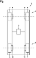
- the figure shows a schematic representation of a motor vehicle 1 which has a first wheel axle 2 with wheels 3 and 4 and a second wheel axle 5 with wheels 6 and 7 .
- the first wheel axle 2 is, for example, a front axle and the second wheel axle 5 is a rear axle of the motor vehicle 1.
- the wheels 3 and 4 are front wheels and the wheels 6 and 7 are rear wheels of the motor vehicle 1.
- the wheels 3 and 6 are a first lane and the wheels 4 and 7 assigned to a second lane. This means that the wheels 3 and 6 are arranged on a first side and the wheels 4 and 7 are arranged on a second side of the motor vehicle 1 in the lateral direction.
- the wheels 3, 4, 6 and 7 can be driven by means of traction machines 8, 9, 10 and 11, with each of the traction machines 8, 9, 10 and 11 being assigned a control unit which is not shown here.
- the control unit of each of the traction machines 8, 9, 10 and 11 is connected to a central control unit 12.
- a target torque is set on the control unit of the respective traction machine 8, 9, 10 and 11 and a torque control for setting one of the traction machines 8, 9, 10 and 11 to perform the actual torque generated.
- a target speed range is set on the control unit and if the actual speed of wheel 3, 4, 6 or 7 is in the target speed range, the actual torque is regulated to the target torque in the course of torque control.
- the torque control is carried out in such a way that the actual speed changes in the direction of the speed setpoint range.
- the wheel is one of the wheels 3, 4 of the first wheel axle 2 and the other wheel is one of the wheels 6 and 7 of the second wheel axle 5 or vice versa.
- the wheel is one of wheels 8 and 10 and the other wheel is one of wheels 9 and 11, with the wheel and the other wheel being assigned to the same wheel axle, for example the first wheel axle 2 or the second wheel axle 5 .
Landscapes
- Engineering & Computer Science (AREA)
- Transportation (AREA)
- Mechanical Engineering (AREA)
- Chemical & Material Sciences (AREA)
- Combustion & Propulsion (AREA)
- Electric Propulsion And Braking For Vehicles (AREA)
Description
- Die Erfindung betrifft ein Verfahren zum Betreiben eines Kraftfahrzeugs, mit einer Antriebseinrichtung, die zumindest eine elektrische Traktionsmaschine aufweist, wobei zum Bereitstellen eines Drehmoments an einem Rad des Kraftfahrzeugs an einem Steuergerät der Traktionsmaschine ein Solldrehmoment eingestellt und mittels des Steuergeräts eine Drehmomentregelung zum Einstellen eines von der Traktionsmaschine erzeugten Istdrehmoments durchgeführt wird. Die Erfindung betrifft weiterhin ein Kraftfahrzeug.
- Aus dem Stand der Technik ist beispielsweise die Druckschrift
US 9,707,944 B2 - Die
WO 2013 041 311 A1 beschreibt eine Steuereinrichtung, die eine elektrische Maschine zum Erzeugen eines Bremsmoments oder eines Beschleunigungsmoments steuert, um das Rad besser im Punkt des optimalen Schlupfes zu halten. - Es ist Aufgabe der Erfindung, ein Verfahren zum Betreiben eines Kraftfahrzeugs vorzuschlagen, welches gegenüber bekannten Verfahren Vorteile aufweist, insbesondere auf einfache Art und Weise während eines Bremsvorgangs und/oder eines Beschleunigungsvorgangs des Kraftfahrzeugs eine starke Beschleunigung beziehungsweise Verzögerung des Kraftfahrzeugs ermöglicht, wobei gleichzeitig ein stabiles Fahrverhalten des Kraftfahrzeugs sichergestellt ist.
- Dies wird erfindungsgemäß mit einem Verfahren zum Betreiben eines Kraftfahrzeugs mit den Merkmalen des Anspruchs 1 erreicht. Dabei ist vorgesehen, dass an dem Steuergerät zusätzlich ein Drehzahlsollbereich eingestellt und bei Vorliegen einer Istdrehzahl des Rads in dem Drehzahlsollbereich das Istdrehmoment im Zuge der Drehmomentregelung auf das Solldrehmoment geregelt wird und bei Vorliegen der Istdrehzahl außerhalb des Drehzahlsollbereichs die Drehmomentregelung derart durchgeführt wird, dass sich die Istdrehzahl in Richtung des Drehzahlsollbereichs verändert.
- Das Kraftfahrzeug verfügt über die Antriebseinrichtung, welche dem Antreiben des Kraftfahrzeugs dient, also dem Bereitstellen eines auf das Antreiben des Kraftfahrzeugs gerichteten Drehmoments. Zum Bereitstellen des Drehmoments weist die Antriebseinrichtung die elektrische Traktionsmaschine auf, welche mit dem Rad des Kraftfahrzeugs gekoppelt oder zumindest koppelbar ist.
- Zum Bereitstellen des Drehmoments an dem Rad werden die Antriebseinrichtung und mithin die Traktionsmaschine entsprechend angesteuert. So wird zum Bereitstellen des Drehmoments an dem Rad das Solldrehmoment an dem Steuergerät der Traktionsmaschine eingestellt. Das Solldrehmoment kann beispielsweise einem Vorgabedrehmoment entsprechen, welches wiederum von einem Fahrer des Kraftfahrzeugs und/oder einer Fahrerassistenzeinrichtung des Kraftfahrzeugs vorgegeben ist.
- Das Steuergerät ist zum Durchführen der Drehmomentregelung vorgesehen und ausgebildet. Die Drehmomentregelung umfasst das regelnde Einstellen des von der Traktionsmaschine für das Rad bereitgestellten Istdrehmoments. Zumindest zeitweise wird im Rahmen der Drehmomentregelung das von der Traktionsmaschine erzeugte Istdrehmoment auf das Solldrehmoment eingestellt. Als Stellgröße dient insoweit das Istdrehmoment, wohingegen als Regelgröße beispielsweise die Differenz zwischen dem Istdrehmoment und dem Solldrehmoment herangezogen wird.
- Um das Fahrverhalten des Kraftfahrzeugs zu verbessern, wird an dem Steuergerät, welches der Durchführung der Drehmomentregelung dient, zusätzlich zu dem Solldrehmoment der Drehzahlsollbereich eingestellt. Der Drehzahlsollbereich beschreibt den Drehzahlbereich, in welchem die Istdrehzahl des Rads idealerweise liegt. Der Drehzahlsollbereich kann zur Erzielung verschiedener Vorteile auf Grundlage verschiedener Randbedingungen gewählt werden. In jedem Fall ist es jedoch vorgesehen zu prüfen, ob die Istdrehzahl in dem Drehzahlsollbereich liegt. Ist dies der Fall, so wird im Rahmen der Drehzahlregelung das Istdrehmoment, welches die Traktionsmaschine bereitstellt, auf das Solldrehmoment eingeregelt, also regelnd auf das Solldrehmoment eingestellt.
- Liegt hingegen die Istdrehzahl außerhalb des Drehzahlsollbereichs, so kann das Solldrehmoment bei der Drehmomentregelung außer Acht bleiben oder zumindest nur untergeordnet Beachtung finden. Vielmehr wird nun im Rahmen der Drehmomentregelung eine Drehzahlregelung derart durchgeführt, dass sich die Istdrehzahl in Richtung des Drehzahlsollbereichs verändert. Diese Drehzahlregelung wird vorzugsweise durchgeführt, bis die Istdrehzahl in dem Drehzahlsollbereich liegt. Anschließend kann wieder das Istdrehmoment in Richtung des Solldrehmoments geregelt werden, nämlich vorzugsweise solange, bis die Istdrehzahl wieder außerhalb des Drehzahlsollbereichs liegt. Vorzugsweise wird auch im Rahmen der Drehzahlregelung, also falls die Istdrehzahl außerhalb des Drehzahlsollbereichs liegt, das Istdrehmoment soweit als möglich auf dem Solldrehmoment gehalten oder zumindest in Richtung des Solldrehmoments verändert, sofern die Istdrehzahl dies zulässt.
- Durch die zusätzliche Vorgabe des Drehzahlsollbereichs kann in zahlreichen Fahrsituationen die Fahrstabilität des Kraftfahrzeugs und/oder die Beschleunigung des Kraftfahrzeugs verbessert werden. In diesem Zuge sei darauf hingewiesen, dass unter dem Beschleunigen sowohl ein positives Beschleunigen als auch ein negatives Beschleunigen verstanden wird. Im Falle des positiven Beschleunigens nimmt die Geschwindigkeit des Kraftfahrzeugs in seiner Hauptfahrrichtung, also nach vorne, zu. Im Falle der negativen Beschleunigung verringert sich die Geschwindigkeit in die Hauptfahrrichtung. Das negative Beschleunigen kann insoweit auch als Verzögern oder Bremsen des Kraftfahrzeugs bezeichnet werden.
- Die zusätzliche Vorgabe des Drehzahlsollbereichs ist beispielsweise bei einem Bremsvorgang des Kraftfahrzeugs sinnvoll. Das maximal an dem Rad absetzbare Drehmoment wird durch eine Schlupfkurve bestimmt, welche den Zusammenhang zwischen dem absetzbaren Drehmoment und dem Schlupf wiedergibt. Der sich in der Schlupfkurve niederschlagende Zusammenhang zwischen Radschlupf und maximal absetzbarem Drehmoment gilt sowohl für positive als auch negative Drehmomente. Um eine maximale Beschleunigung, insbesondere eine maximale Verzögerung, zu erreichen, ist es notwendig, das an dem Rad anliegende Drehmoment derart einzustellen, dass es einem Drehmoment entspricht, für welches die Schlupfkurve ein Maximum, insbesondere ein globales Maximum, aufweist.
- Üblicherweise steigt das absetzbare Drehmoment ausgehend von Null mit zunehmendem Schlupf zunächst an, insbesondere linear. Anschließend steigt es bis zu dem maximal absetzbaren Drehmoment an, üblicherweise nicht linear, um anschließend mit weiter zunehmendem Schlupf rasch abzufallen. Ein Schlupf oberhalb des Schlupfs, welcher bei dem maximal absetzbaren Drehmoment auftritt, sollte also vermieden werden, weil das absetzbare Drehmoment mit zunehmendem Schlupf stark absinkt.
- Durch die beschriebene Vorgehensweise mit dem Einstellen des Solldrehmoments und des Drehzahlsollbereichs an dem Steuergerät soll nun im Rahmen der Drehmomentregelung eine Art Antiblockierregelung durchgeführt werden. Hierbei wird die Traktionsmaschine verwendet, um auf das Rad ein Bremsdrehmoment aufzuprägen, wobei vorzugsweise dieses Bremsdrehmoment dem maximal absetzbaren Drehmoment entspricht.
- Wäre die aktuelle Schlupfkurve für das Rad bekannt, so müsste lediglich unter Verwendung der Traktionsmaschine das dem maximal absetzbaren Drehmoment entsprechende Drehmoment an dem Rad angelegt werden. Dies ist in der Praxis jedoch üblicherweise nicht realisierbar, weil zum einen die Schlupfkurve nicht exakt bekannt ist und sich zum anderen permanent verändert. Weiterhin kann eine Momentengenauigkeit der Traktionsmaschine stark streuen.
- Es ist daher sinnvoll, den Schlupf auszuregeln, anstatt über das Drehmoment das Maximum der Schlupfkurve zu erreichen, weil die Änderung des optimalen Schlupfs während der Verzögerung des Kraftfahrzeugs wesentlich geringer ist als die Änderung des maximal absetzbaren Drehmoments. Zudem kann an der Traktionsmaschine wesentlich rascher eine bestimmte Drehzahl eingestellt werden als ein Drehmoment. Ersteres führt dazu, dass weniger dynamische Regeleingriffe notwendig sind, letzteres zu einer höheren Stellgenauigkeit.
- Weiterhin kann das beschriebene Verfahren für eine optimale Drehmomentverteilung zwischen mehreren Radachsen des Kraftfahrzeugs und/oder zwischen mehreren Rädern derselben Radachse herangezogen werden. In andern Worten ist das Rad beispielsweise einer ersten Radachse und ein weiteres Rad des Kraftfahrzeugs einer von der ersten Radachse verschiedenen zweiten Radachse zugeordnet, wobei die Radspur des weiteren Rads der Radspur des Rads entspricht.
- Vorzugsweise wird für das weitere Rad dieselbe Vorgehensweise durchgeführt wie für das Rad. Es ist insoweit vorzugsweise vorgesehen, dass zum Bereitstellen eines Drehmoments an dem weiteren Rad an dem Steuergerät oder einem weiteren Steuergerät einer dem weiteren Rad zugeordneten weiteren Traktionsmaschine ein Solldrehmoment eingestellt und mittels des Steuergeräts oder des weiteren Steuergeräts eine Drehmomentregelung zum Einstellen eines von der weiteren Traktionsmaschine erzeugten Istdrehmoments durchgeführt wird. Dabei ist weiter bevorzugt vorgesehen, dass an dem Steuergerät oder dem weiteren Steuergerät zusätzlich ein Drehzahlsollbereich eingestellt und bei Vorliegen einer Istdrehzahl des weiteren Rads in dem Drehzahlsollbereich das Istdrehmoment im Zuge der Drehmomentregelung auf das Solldrehmoment geregelt wird und bei Vorliegen der Istdrehzahl außerhalb des Drehzahlsollbereichs die Drehmomentregelung derart durchgeführt wird, dass sich die Istdrehzahl in Richtung des Drehzahlsollbereichs verändert. Das Solldrehmoment und/oder der Drehzahlsollbereich können hierbei für das Rad und das weitere Rad jeweils verschieden oder identisch gewählt sein.
- Die Erfindung sieht vor, dass der Drehzahlsollbereich nach unten von einer Drehzahluntergrenze und nach oben von einer Drehzahlobergrenze begrenzt ist, die anhand einer Fahrgeschwindigkeit des Kraftfahrzeugs und einem Schlupfoptimum des Rads ermittelt werden.
- Der Drehzahlsollbereich wird von der Drehzahluntergrenze und von der Drehzahlobergrenze begrenzt.
- Sowohl die Drehzahluntergrenze als auch die Drehzahlobergrenze werden (jeweils) anhand der Fahrgeschwindigkeit und des Schlupfoptimums des Rads ermittelt.
- Die Fahrgeschwindigkeit wird beispielsweise anhand wenigstens eines Sensors gemessen und/oder abgeschätzt. Das Schlupfoptimum des Rads wird vorzugsweise abgeschätzt, insbesondere ebenfalls unter Verwendung eines geeigneten Sensors. Beispielsweise wird das Schlupfoptimum aus der Schlupfkurve ermittelt, welche wiederum durch entsprechendes Betreiben des Kraftfahrzeugs ermittelt wird.
- Beispielsweise wird zum Ermitteln der Schlupfkurve ein an einer Hinterachse des Kraftfahrzeugs anliegendes Drehmoment von einem an einer Vorderachse des Kraftfahrzeugs anliegenden Drehmoment verschieden gewählt. Bevorzugt werden für die an der Vorderachse und der Hinterachse anliegende Drehmomente unterschiedliche Werte abgefahren und die jeweiligen Raddrehzahlen an der Vorderachse und der Hinterachse gemessen. Aus den Drehzahlen lässt sich nachfolgend der Schlupf beziehungsweise die Schlupfkurve bestimmen. Das Schlupfoptimum entspricht dem Schlupf bei dem maximal absetzbaren Drehmoment beziehungsweise liegt bei diesem vor.
- Bevorzugt sind die Drehzahluntergrenze und die Drehzahlobergrenze voneinander verschieden, insbesondere ist die Drehzahlobergrenze größer als die Drehzahluntergrenze. Beispielsweise wird die Drehzahluntergrenze aus der Fahrgeschwindigkeit und einem Schlupf des Rads ermittelt, welcher um einen bestimmten Betrag über dem Schlupfoptimum liegt und die Drehzahlobergrenze aus der Fahrgeschwindigkeit und einem Schlupf, welcher um einen bestimmten Wert unter dem Schlupfoptimum liegt. Der bestimmte Wert ist vorzugsweise für die Drehzahluntergrenze und die Drehzahlobergrenze derselbe, sodass der Schlupf für die Drehzahluntergrenze und der Schlupf für die Drehzahlobergrenze symmetrisch bezüglich des Schlupfoptimums gewählt sind. In anderen Worten wird die Drehzahluntergrenze entsprechend einem negativen Schlupfoptimum und die Drehzahlobergrenze entsprechend einem positivem Schlupfoptimum gewählt. Vorzugsweise liegen die Drehzahluntergrenze und die Drehzahlobergrenze in jedem Fall jeweils zwischen dem negativen Schlupfoptimum und dem positiven Schlupfoptimum (diese Werte jeweils eingeschlossen).
- Im Rahmen einer weiteren Ausgestaltung der Erfindung kann vorgesehen sein, dass bei einem Bremsvorgang des Kraftfahrzeugs ein erster Teil eines an dem Rad anliegenden Bremsdrehmoments mittels einer Betriebsbremse und ein zweiter Teil mittels der Traktionsmaschine erzeugt wird, wobei der erste Teil kleiner gewählt wird als ein in dem Schlupfoptimum über das Rad absetzbare Drehmoment. Das Bremsdrehmoment, welches an dem Rad anliegen soll, wird also in die beiden Teile, nämlich den ersten Teil und den zweiten Teil aufgeteilt. Der erste Teil wird mittels der Betriebsbremse bereitgestellt, wohingegen der zweite Teil von der Traktionsmaschine erzeugt wird.
- Das mittels der Betriebsbremse an dem Rad einstellbare Drehmoment beziehungsweise Bremsdrehmoment kann üblicherweise lediglich langsamer eingeregelt werden als das mittels der Traktionsmaschine einstellbare Drehmoment. Aus diesem Grund ist es nun vorgesehen, den ersten Teil derart zu wählen, dass er kleiner ist als das maximal absetzbare Drehmoment, also das in dem Schlupfoptimum über das Rad absetzbare Drehmoment. Auf diese Weise wird sichergestellt, dass der erste Teil des Bremsdrehmoments allein keine Überschreitung des maximal absetzbaren Drehmoments bewirkt.
- Beispielsweise beträgt der erste Teil des Bremsdrehmoments höchstens 90 %, höchstens 80 %, höchstens 75 %, höchstens 70 %, höchstens 60 % oder höchstens 50 % des maximal absetzbaren Drehmoments. Der Rest des angeforderten Bremsdrehmoments wird in Form des zweiten Teils mittels der Traktionsmaschine bereitgestellt und ist rasch ausregelbar. Der zweite Teil wird dabei derart gewählt, dass das Bremsdrehmoment insgesamt dem maximal absetzbaren Drehmoment entspricht. Auf diese Weise wird ein besonders effektiver Bremsvorgang des Kraftfahrzeugs umgesetzt.
- Eine weitere Ausgestaltung der Erfindung sieht vor, dass bei dem Bremsvorgang der zweite Teil des Bremsdrehmoments schneller aufgebaut wird als der erste Teil, wobei der zweite Teil des Bremsdrehmoments vergrößert wird, bis die Summe aus dem ersten Teil und dem zweiten Teil einem Sollbremsdrehmoment entspricht, und wobei nach dem Erreichen des Sollbremsdrehmoments durch die Summe aus dem ersten Teil und dem zweiten Teil der erste Teil bei dem Sollbremsdrehmoment entsprechender Summe weiter vergrößert wird. Üblicherweise ist mittels der Traktionsmaschine rascher das Bremsdrehmoment an dem Rad aufbaubar als mittels der Betriebsbremse. Der zweite Teil des Bremsdrehmoments wird insoweit schneller aufgebaut als der erste Teil.
- Der erste Teil des Bremsdrehmoments wird jedoch auch nach dem Erreichen des Sollbremsdrehmoments durch die Summe aus dem ersten Teil und dem zweiten Teil weiter vergrößert, nämlich bis er sein vorgesehenes Maximum erreicht hat. Vor dem Erreichen des Sollbremsdrehmoments durch die Summe aus dem ersten Teil und dem zweiten Teil werden der erste Teil und der zweite Teil des Bremsdrehmoments unabhängig voneinander vergrößert. Ist das Sollbremsdrehmoment jedoch erreicht, so soll der erste Teil weiter vergrößert werden, wobei jedoch die Summe der beiden Teile weiterhin dem Sollbremsdrehmoment entsprechen soll.
- Das bedeutet schlussendlich, dass mit dem weiteren Vergrößern des ersten Teils des Sollbremsdrehmoments der zweite Teil verringert wird, nämlich derart, dass die Summe aus beiden Teilen weiterhin dem Sollbremsdrehmoment entspricht. Hierdurch wird ein äußerst rascher Aufbau des Bremsdrehmoments erreicht, nämlich unter Verwendung der Traktionsmaschine. Mithilfe der Betriebsbremse, welche vorzugsweise eine hydraulische Bremse ist, wird eine Grundlast des Bremsdrehmoments bereitgestellt. Mittels der Traktionsmaschine wird hingegen drehzahlbasiert ein zusätzliches Moment erzeugt, welches ein Verzögern des Kraftfahrzeugs mit maximal absetzbarem Drehmoment sicherstellt.
- Ändert sich während des Bremsvorgangs das Sollbremsdrehmoment, so werden der erste Teil und der zweite Teil des Bremsdrehmoments stets nachgeführt. Dieses Nachführen erfolgt dabei derart, dass stets ein zuverlässiges Bereitstellen des Sollbremsdrehmoments möglich ist. Insbesondere ist es vorgesehen, dass der erste Teil stets mindestens 50 %, mindestens 60 %, mindestens 70 % oder mindestens 75 % des Sollbremsdrehmoments entspricht. Unterschreitet der erste Teil diesen Wert, so wird er vergrößert, bis er ihn erreicht hat. Entsprechend wird der zweite Teil derart verändert, dass die Summe aus den beiden Teilen weiterhin dem Sollbremsdrehmoment entspricht.
- Hierdurch werden die Drehmomentpuffer sowohl der Betriebsbremse als auch der Traktionsmaschine aufrechterhalten. Sollte es vorkommen, dass während des Bremsvorgangs bereits der erste Teil des Bremsdrehmoments zu einem Blockieren des Rads führt, so kann der zweite Teil derart gewählt werden, dass er diesem Verhalten entgegenwirkt. Beispielsweise wird der zweite Teil rasch auf Null heruntergefahren. Alternativ kann sogar der zweite Teil ein von dem ersten Teil verschiedenes Vorzeichen aufweisen, sodass mittels der Traktionsmaschine der Betriebsbremse entgegengearbeitet wird, um das Blockieren des Rads zu verhindern beziehungsweise zu beenden. Zusätzlich oder alternativ kann es vorgesehen sein, dass für den ersten Teil des Bremsdrehmoments ein Antiblockierverfahren durchgeführt wird, also die Betriebsbremse periodisch geöffnet und wieder zum Bewirken des ersten Teils des Bremsdrehmoments eingestellt wird.
- Eine besonders bevorzugte weitere Ausführungsform der Erfindung sieht vor, dass bei einem Beschleunigungsvorgang des Kraftfahrzeugs bei Überschreiten der Drehzahlobergrenze durch die Istdrehzahl des Rads das Istdrehmoment reduziert wird, bis die Istdrehzahl kleiner oder gleich der Drehzahlobergrenze ist, und das reduzierte Istdrehmoment oder die Differenz zwischen dem Solldrehmoment und dem reduzierten Istdrehmoments nach oder während des Reduzierens an ein weiteres Steuergerät übermittelt wird. Sobald die Istdrehzahl des Rads die Drehzahlobergrenze überschreitet, so wird darauf geschlossen, dass das Rad durchdreht beziehungsweise das Rad mit einem Drehmoment beaufschlagt ist, welches größer ist als das maximal absetzbare Drehmoment. In diesem Fall soll die Istdrehzahl des Rads verringert werden, bis sie wieder kleiner oder gleich der Drehzahlobergrenze ist. Hierdurch wird das von der Traktionsmaschine an dem Rad bereitgestellte Istdrehmoment verringert. Das reduzierte Istdrehmoment beziehungsweise der Betrag, um welchen das Istdrehmoment ausgehend von dem Solldrehmoment reduziert wurde, wird bereits während des Reduzierens oder erst nach Abschluss des Reduzierens an das weitere Steuergerät übermittelt.
- Eine derartige Vorgehensweise ist insbesondere vorgesehen, falls zusätzlich zu der Traktionsmaschine, mittels welcher das Rad des Kraftfahrzeugs antreibbar ist, eine weitere Traktionsmaschine vorliegt, mittels welcher ein weiteres Rad des Kraftfahrzeugs antreibbar ist. Vorzugsweise sind das Rad und das weitere Rad unterschiedlichen Radachsen des Kraftfahrzeugs zugeordnet, beispielsweise das Rad einer Hinterachse oder einer Vorderachse des Kraftfahrzeugs und das weitere Rad der jeweils anderen Radachse, wobei das Rad und das weitere Rad derselben Radspur zugeordnet sind. Das weitere Steuergerät dient beispielsweise dazu, für die Traktionsmaschine und die weitere Traktionsmaschine jeweils ein Solldrehmoment zu ermitteln und an diesen einzustellen.
- Es ist vor dem Hintergrund der vorstehenden Ausführungen also bevorzugt vorgesehen, dass bei dem Beschleunigungsvorgang des Kraftfahrzeugs bei Überschreiten der Drehzahlobergrenze durch die Istdrehzahl des Rads das Istdrehmoment reduziert wird, bis die Istdrehzahl kleiner oder gleich der Drehzahlobergrenze ist, und die Differenz zwischen dem Solldrehmoment und dem reduzierten Istdrehmoments dem weiteren Rad zusätzlich zugeschlagen wird. Die Differenz wird also auf das für das weitere Rad beziehungsweise die weitere Traktionsmaschine geltende Solldrehmoment aufgeschlagen beziehungsweise zu diesem hinzuaddiert. In anderen Worten ist eine absolute Drehzahlbegrenzung beschrieben.
- Eine bevorzugte Weiterbildung der Erfindung sieht vor, dass das Rad einer ersten Radachse und ein weiteres Rad des Kraftfahrzeug einer von der ersten Radachse verschiedenen zweiten Radachse zugeordnet sind, wobei zum Bereitstellen eines Drehmoments an dem weiteren Rad an einem weiteren Steuergerät einer weiteren Traktionsmaschine ein weiteres Solldrehmoment eingestellt und mittels des weiteren Steuergeräts eine Drehmomentregelung zum Einstellen eines von der weiteren Traktionsmaschine erzeugten weiteren Istdrehmoments durchgeführt wird, wobei dem weiteren Solldrehmoment die Differenz zwischen dem Solldrehmoment und dem reduzierten Istdrehmoment zugeschlagen wird.
- Für die weitere Traktionsmaschine, das weitere Steuergerät und das weitere Rad können die Ausführungen im Rahmen dieser Beschreibung für die Traktionsmaschine, das Steuergerät und das Rad zusätzlich herangezogen werden. Bevorzugt sind die weitere Traktionsmaschine, das weitere Steuergerät und das weitere Rad also analog zu der Traktionsmaschine, dem Steuergerät und dem Rad ausgestaltet, mit dem Unterschied, dass das weitere Rad einer anderen Radachse zugeordnet ist als das Rad.
- An dem Steuergerät wird das Solldrehmoment und an dem weiteren Steuergerät das weitere Solldrehmoment eingestellt. Das Solldrehmoment und das weitere Solldrehmoment werden beispielsweise von einem Zentralsteuergerät aus einem Vorgabegesamtdrehmoment ermittelt und an das Steuergerät und das weitere Steuergerät übermittelt. Um die Reduzierung des Istdrehmoments an dem Rad durch entsprechendes einstellen der Traktionsmaschine auszugleichen, soll das Drehmoment, um welches das Istdrehmoment der Traktionsmaschine ausgehend von dem Solldrehmoment reduziert wurde, von der weiteren Traktionsmaschine über das an ihr eingestellte weitere Solldrehmoment zusätzlich an dem weiteren Rad angelegt werden.
- Das bedeutet, dass bei einer Reduzierung des Istdrehmoments an einer der Radachsen aufgrund der Drehzahlbegrenzung auf die jeweilige Drehzahlobergrenze das Drehmoment an der jeweils anderen Radachse um den Betrag der Reduzierung vergrößert wird. Dies gilt selbstverständlich bevorzugt in beide Richtungen, sodass eine Drehmomentreduzierung an der ersten Radachse durch eine Drehmomenterhöhung an der zweiten Radachse und eine Drehmomentreduzierung an der zweiten Radachse durch eine Drehmomenterhöhung an der ersten Radachse ausgeglichen wird. Im Falle der Zuordnung des Rads zu der ersten Radachse und des weiteren Rads zu der zweiten Radachse wird bevorzugt unter der Drehzahl des Rads eine Drehzahl der ersten Radachse und/oder eine mittlere Drehzahl von an der ersten Radachse vorliegenden Rädern verstanden. Analog ist die Drehzahl des weiteren Rads eine Drehzahl der zweiten Radachse und/oder eine mittlere Drehzahl von an der zweiten Radachse vorliegenden weiteren Rädern.
- Eine bevorzugte weitere Ausführungsform der Erfindung sieht vor, dass ein Zentralsteuergerät ein Vorgabegesamtdrehmoment in ein erstes Vorgabedrehmoment und ein zweites Vorgabedrehmoment aufteilt, wobei das Solldrehmoment gleich dem ersten Vorgabedrehmoment und das weitere Solldrehmoment gleich dem zweiten Vorgabedrehmoment gesetzt und anschließend das Solldrehmoment an dem Steuergerät und das weitere Solldrehmoment an dem weiteren Steuergerät eingestellt werden, wobei vor dem Einstellen dem weiteren Solldrehmoment die Differenz zwischen dem Solldrehmoment und dem reduzierten Istdrehmoment zugeschlagen wird.
- Das Vorgabegesamtdrehmoment ist beispielsweise ein von dem Fahrer des Kraftfahrzeugs und/oder einer Fahrerassistenzeinrichtung des Kraftfahrzeugs vorgegebene Drehmoment. Dieses wird in das erste Vorgabedrehmoment und das zweite Vorgabedrehmoment aufgeteilt, sodass die Summe aus den beiden Vorgabedrehmomenten dem Vorgabegesamtdrehmoment entspricht. Dieses Aufteilen erfolgt beispielsweise gemäß einer vorgegebenen Aufteilung, gemäß welcher ein bestimmter Anteil des Vorgabegesamtdrehmoments an einer Hinterachse und der Rest an der Vorderachse anliegen soll.
- Das Solldrehmoment wird nun gleich dem ersten Vorgabedrehmoment und das weitere Solldrehmoment gleich dem zweiten Vorgabedrehmoment gesetzt. Anschließend wird eine Korrektur des Solldrehmoments und/oder des weiteren Solldrehmoments vorgenommen. Insbesondere wird die Differenz zwischen dem Solldrehmoment und dem reduzierten Istdrehmoment dem weiteren Solldrehmoment zugeschlagen. Erfolgt auch für die weitere Traktionsmaschine beziehungsweise das weitere Rad eine Reduktion des Istdrehmoments, so wird dem Solldrehmoment die Differenz zwischen dem weiteren Solldrehmoment und dem weiteren reduzierten Istdrehmoment zugeschlagen. Anschließend wird das Solldrehmoment an dem Steuergerät und das weitere Solldrehmoment an dem weiteren Steuergerät eingestellt.
- Das Aufteilen des Vorgabegesamtdrehmoments in das erste Vorgabedrehmoment und das zweite Vorgabedrehmoment kann beispielsweise im Rahmen einer Vorsteuerung erfolgen, sodass im Idealfall an dem Steuergerät und dem weiteren Steuergerät Solldrehmomente eingestellt werden, welche dem jeweils maximal absetzbaren Drehmoment an dem entsprechenden Rad entsprechen. Zur Vorsteuerung kann beispielsweise wenigstens eine Umgebungsbedingung herangezogen werden, beispielsweise eine Außentemperatur, eine Neigung eines Untergrunds, auf welchem das Kraftfahrzeug bewegt wird, ein Niederschlagsparameter und/oder eine Luftfeuchtigkeit.
- Der Niederschlagsparameter entspricht beispielsweise einem Schaltzustand eines Scheibenwischers des Kraftfahrzeugs und gibt insoweit an, ob ein Niederschlag vorliegt oder nicht. In jedem Fall kann es vorgesehen sein, bei einer Drehzahlbegrenzung der Traktionsmaschine und/oder der weiteren Traktionsmaschine das jeweils vorliegende Istdrehmoment als maximal absetzbares Drehmoment zwischenzuspeichern. Auch dieses maximal absetzbare Drehmoment, welches für die Traktionsmaschine und/oder die weitere Traktionsmaschine (jeweils) vorliegt, kann zur Vorsteuerung herangezogen werden, um die Notwendigkeit für die Drehzahlbegrenzung im Idealfall zu verhindern.
- Mit der beschriebenen Vorgehensweise kann sichergestellt werden, dass stets das maximal mögliche Drehmoment über das Rad und/oder das weitere Rad abgesetzt wird, sodass das Beschleunigungsverhalten des Kraftfahrzeugs deutlich verbessert ist. Aufgrund der der Drehmomentregelung der Traktionsmaschine und/oder der weiteren Traktionsmaschine überlagerten Drehzahlregelung, welche eine höhere Priorität genießt als die Drehmomentregelung, wird ein sehr schnelles Regelverhalten erzielt.
- Eine bevorzugte Ausgestaltung der Erfindung sieht vor, dass das Rad und das weitere Rad derselben der Radachsen und unterschiedlichen Radspuren zugeordnet oder unterschiedlichen der Radachsen und derselben Radspur zugeordnet sind, wobei ein Differenzdrehzahlmaximum und ein Differenzdrehzahlminimum für eine Drehzahldifferenz zwischen der Drehzahl des Rads und der Drehzahl des weiteren Rads ermittelt werden und die Drehzahlobergrenze für das Rad aus der Istdrehzahl des weiteren Rads und dem Differenzdrehzahlmaximum und die Drehzahlobergrenze für das weitere Rad aus der Istdrehzahl des Rads und dem Differenzdrehzahlminimum ermittelt wird. In anderen Worten wird die Einhaltung einer Differenzdrehzahl beschrieben.
- Es ist nun also beispielsweise vorgesehen, dass die Räder nicht mehr unterschiedlichen Radachsen, sondern vielmehr derselben Radachse zugeordnet sind, jedoch verschiedenen Radspuren. Das bedeutet, dass die Räder auf unterschiedlichen Seiten des Kraftfahrzeugs vorliegen. Beispielsweise ist das Rad ein linkes Rad und das weitere Rad ein rechtes Rad. Es kann jedoch auch vorgesehen sein, dass die Räder unterschiedlichen Radachsen zugeordnet sind. In diesem Fall sind die Räder derselben Radspur zugeordnet.
- Aus den Ausführungen im Rahmen dieser Beschreibung wird deutlich, dass das Kraftfahrzeug über einen radindividuellen Antrieb beziehungsweise einen Einzelradantrieb verfügen kann, wobei das Rad mittels der Traktionsmaschine und das weitere Rad mittels der weiteren Traktionsmaschine antreibbar ist. Das bedeutet, dass zwischen dem Rad und dem weiteren Rad keine unmittelbare mechanische Kopplung vorliegt, sondern lediglich mittelbar über den Untergrund, auf welchem sie sich befinden.
- Um ein hervorragendes Fahrverhalten des Kraftfahrzeugs sicherzustellen, ist es daher notwendig, die beiden Räder mit zumindest ähnlichen Drehzahlen, idealerweise identischen Drehzahlen, anzutreiben. Gleichzeitig sollen jedoch, insbesondere während einer Kurvenfahrt des Kraftfahrzeugs, unterschiedliche Drehzahlen der Räder zugelassen werden. Hierzu wird ein Differenzzahldrehzahlband festgelegt, welches nach unten von dem Differenzdrehzahlminimum und nach oben von dem Differenzdrehzahlmaximum begrenzt ist. Das Differenzdrehzahlmaximum stellt einen maximal zulässigen Wert für die Drehzahldifferenz und das Differenzdrehzahlminimum einen minimal zulässigen Wert für die Drehzahldifferenz dar, wobei die Drehzahldifferenz die Differenz zwischen der Drehzahl des Rads und der Drehzahl des weiteren Rads beschreibt.
- Die vorstehend bereits erwähnte Drehzahlobergrenze wird für das Rad nun aus der Istdrehzahl des weiteren Rads und dem Differenzdrehzahlmaximum und die Drehzahlobergrenze für das weitere Rad aus der Istdrehzahl des Rads und dem Differenzdrehzahlminimum ermittelt. Beispielsweise ergibt sich die Drehzahlobergrenze für das Rad aus der Istdrehzahl des weiteren Rads zuzüglich des Differenzdrehzahlmaximums und die Drehzahlobergrenze für das weitere Rad aus der Istdrehzahl des Rads abzüglich des Differenzdrehzahlminimums, wobei das Differenzdrehzahlmaximum positiv und das Differenzdrehzahlminimum negativ ist. Mit einer derartigen Vorgehensweise wird auch für das radindividuell angetriebene Kraftfahrzeug das Verhalten einer Quersperre zwischen den Rädern mit hoher Genauigkeit abgebildet, sodass ein hoher Fahrkomfort und/oder eine gute Traktion beziehungsweise eine gute Fahrdynamik gewährleistet ist, insbesondere für die Ausgestaltung, gemäß welcher die Räder unterschiedlichen Radspuren zugeordnet sind und an derselben oder an unterschiedlichen Radachsen vorliegen.
- Das Differenzdrehzahlminimum und das Differenzdrehzahlmaximum sind vorzugsweise voneinander verschieden, insbesondere ist das Differenzdrehzahlmaximum größer als das Differenzdrehzahlminimum. Beispielsweise können das Differenzdrehzahlmaximum und das Differenzdrehzahlminimum aus der Fahrgeschwindigkeit des Kraftfahrzeugs ermittelt werden. Zusätzlich kann ein Lenkwinkel des Kraftfahrzeugs bei dem Ermitteln des Differenzdrehzahlmaximums und des Differenzdrehzahlminimums Verwendung finden.
- Schließlich kann im Rahmen einer bevorzugten weiteren Ausgestaltung der Erfindung vorgesehen sein, dass zusätzlich eine Differenzdrehmomentobergrenze bestimmt wird und die Drehmomentregelung für das Rad und für das weitere Rad derart durchgeführt wird, dass die Differenz zwischen dem an dem Rad anliegenden Istdrehmoment und dem an dem weiteren Rad anliegenden weiteren Istdrehmoment kleiner oder gleich der Differenzdrehmomentobergrenze ist. Werden lediglich die Drehzahlobergrenzen für das Rad und das weitere Rad festgelegt, so könnte der Fall eintreten, dass das gesamte Vorgabegesamtdrehmoment über das Rad beziehungsweise das weitere Rad abgesetzt werden soll beziehungsweise die Differenz zwischen den an dem Rad und dem weiteren Rad eingestellten Solldrehmomenten beziehungsweise den an diesen anliegenden Istdrehmomenten ein unterwünscht großes Gierdrehmoment auf das Kraftfahrzeug bewirken. Um dies zu vermeiden, wird zusätzlich zu der Drehzahl die Differenz zwischen den Istdrehmomenten begrenzt, nämlich auf die Differenzdrehmomentobergrenze.
- Es können nun folgende Fälle unterschieden werden: Tritt während des Beschleunigungsvorgangs eine Drehmomentreduktion an einem der Räder auf, so wird das für das jeweils andere der Räder eingestellte Solldrehmoment entsprechend vergrößert. Ist keine weitere Verschiebung des Drehmoments mehr möglich, beispielsweise weil der Antrieb des jeweils anderen Rads bereits ein Istdrehmoment bereitstellt, welches einem maximal einstellbaren Drehmoment beziehungsweise dem Nenndrehmoment der jeweiligen Traktionsmaschine entspricht, so ist es beispielsweise vorgesehen, die zugelassene Differenzdrehzahl zu vergrößern, nämlich durch entsprechendes Anpassen des Differenzdrehzahlmaximums und/oder des Differenzdrehzahlminimums, bis das über das Rad und das weitere Rad absetzbare Drehmoment, also die Summe der beiden Istdrehmomente, dem Vorgabegesamtdrehmoment entspricht.
- Wird beispielsweise das Drehmoment für das Rad begrenzt, so wird geprüft, ob über das weitere Rad ein höheres Drehmoment absetzbar ist. Ist dies der Fall, so wird das für das weitere Rad eingestellte Solldrehmoment vergrößert. Ist die Bedingung hingegen nicht erfüllt, so wird das Differenzdrehzahlminimum erhöht. Greift hingegen die Drehzahlregelung für das weitere Rad, so wird geprüft, ob über das Rad ein höheres Drehmoment absetzbar ist. Ist dies der Fall, so wird das für das Rad eingestellte Solldrehmoment vergrößert. Falls die Bedingung nicht zutrifft, so wird das Differenzdrehzahlmaximum erhöht.
- Wird für keines der Räder eine Drehmomentreduktion durchgeführt, so wird eine eventuell vorliegende Differenz zwischen dem an dem Rad anliegenden Istdrehmoment und dem an dem weiteren Rad anliegenden weiteren Istdrehmoment vorzugsweise durch entsprechendes Einstellen der Solldrehmomente reduziert, nämlich insbesondere bis die Differenz gleich Null ist. Zusätzlich werden das Differenzdrehzahlmaximum und das Differenzdrehzahlminimum wieder auf ihre ursprünglichen Werte zurückgesetzt, sofern sie zuvor verändert beziehungsweise angepasst wurden.
- Insgesamt hat die Begrenzung der Differenz zwischen den Istdrehmomenten auf die Differenzdrehmomentobergrenze die höchste Priorität, gefolgt von der Einhaltung des Drehzahlbands, welches durch das Differenzdrehzahlmaximum und das Differenzdrehzahlminimum begrenzt ist. Geringere Priorität weist die Drehzahlbegrenzung der einzelnen Räder beziehungsweise der einzelnen Traktionsmaschinen und die geringste Priorität das Einstellen des Istdrehmoments auf das vorgegebene Solldrehmoment auf. Während einer Kurvenfahrt des Kraftfahrzeugs kann es vorgesehen sein, Drehmoment gezielt an ein Kurvenäußeres der Räder zu verschieben, damit das Fahrverhalten des Kraftfahrzeugs verbessert wird.
- Im Rahmen dieser Beschreibung sind unter anderem eine absoluten Drehzahlbegrenzung und die Einhaltung einer Differenzdrehzahl erwähnt. Die absolute Drehzahlbegrenzung wird beispielsweise für Räder unterschiedlicher Radachsen durchgeführt, nämlich derart, dass Drehmoment von dem Rad zu dem weiteren Rad oder umgekehrt verschoben wird. Es kann jedoch auch vorgesehen sein, dass die Räder derselben Radachse zugeordnet sind und dennoch das Drehmoment zwischen ihnen verschoben wird. Die Einhaltung der Differenzdrehzahl kann zwischen den Rädern derselben Radachse oder Rädern unterschiedlicher Radachsen erfolgen. Die Prinzipien der absoluten Drehzahlbegrenzung und der Einhaltung der Differenzdrehzahl können separat angewandt, aber auch beliebig miteinander kombiniert werden. Dies gilt insbesondere für Räder derselben Radachse und unterschiedlichen Fahrspuren einerseits sowie für Räder unterschiedlicher Radachsen und derselben Fahrspur andererseits.
- Für Räder unterschiedlicher Radachsen und derselben Fahrspur können folgende Vorgehensweisen vorgesehen sein. Einerseits kann die Differenzdrehzahlbegrenzung realisiert sein, sodass bei sehr niedriger Differenzdrehzahl zwischen den Rädern der Radachsen das Moment schnell umverteilt wird, damit die Drehzahlen beider Achsen möglichst synchron hochlaufen. Andererseits kann im Rahmen der absoluten Drehzahlbegrenzung vorgesehen sein, dass es eine absolute Maximaldrehzahl gibt, weil die Achsen nicht unendlich hochdrehen sollen, um die Räder in dem optimalen Schlupfbereich zu halten. Eine Kombination dieser Maßnahmen hat den Effekt, dass die Räder der Radachsen mit möglichst synchroner Drehzahl bis zum traktionsoptimalen Schlupf hochdrehen. Dann greift die absolute Drehzahlbegrenzung und die Achsen drehen nicht weiter hoch.
- Für Räder derselben Radachse, die unterschiedlichen Fahrspuren zugeordnet sind, können folgende Vorgehensweisen vorgesehen sein: Einerseits kann die Differenzdrehzahlbegrenzung realisiert sein, sodass bei sehr niedriger Differenzdrehzahl zwischen den Rädern das Moment schnell umverteilt wird, damit die Drehzahlen beider Räder möglichst synchron hochlaufen. In die vorgegebene Differenzdrehzahl kann der Kurvenradius mit eingehen, damit ein Verspannen verhindert wird. Hierdurch wird eine sehr gute Fahrdynamik erzielt. In anderen Worten wird dem Rad und dem weiteren Rad eine Differenzdrehzahl aufgezwungen, sodass diese gezielt in unterschiedlichen Schlupfbereichen betrieben werden können. Andererseits kann im Rahmen der absoluten Drehzahlbegrenzung vorgesehen sein, dass eine absolute Maximaldrehzahl vorgegeben wird, weil die Räder nicht unendlich hochdrehen sollen, um die Räder in dem optimalen Schlupfbereich zu halten. Aus diesen Maßnahmen ergibt sich der Effekt, dass beide Räder mit möglichst synchroner Drehzahl bis zum traktionsoptimalen Schlupf hochdrehen. Dann greift die absolute Drehzahlbegrenzung und die Räder drehen nicht weiter hoch.
- Die Erfindung betrifft weiterhin ein Kraftfahrzeug, insbesondere zur Durchführung des Verfahrens gemäß den Ausführungen im Rahmen dieser Beschreibung, mit einer Antriebseinrichtung, die zumindest eine elektrische Traktionsmaschine aufweist, wobei zum Bereitstellen eines Drehmoments an einem Rad des Kraftfahrzeugs an einem Steuergerät der Traktionsmaschine ein Solldrehmoment einstellbar und mittels des Steuergeräts eine Drehmomentregelung zum Einstellen eines von der Traktionsmaschine erzeugten Istdrehmoments durchführbar ist.
- Dabei ist vorgesehen, dass das Kraftfahrzeug dazu ausgebildet ist, an dem Steuergerät zusätzlich einen Drehzahlsollbereich einzustellen und bei Vorliegen einer Istdrehzahl des Rads in dem Drehzahlsollbereich das Istdrehmoment im Zuge der Drehmomentregelung auf das Solldrehmoment zu regeln und bei Vorliegen der Istdrehzahl außerhalb des Drehzahlsollbereichs die Drehmomentregelung derart durchzuführen, dass sich die Istdrehzahl in Richtung des Drehzahlsollbereichs verändert.
- Auf die Vorteile einer derartigen Vorgehensweise beziehungsweise einer derartigen Ausgestaltung des Kraftfahrzeugs wurde bereits hingewiesen. Sowohl das Kraftfahrzeug als auch das Verfahren zu seinem Betreiben können gemäß den Ausführungen im Rahmen dieser Beschreibung weitergebildet sein, sodass insoweit auf dies verwiesen wird.
- Die Erfindung wird nachfolgend anhand der in der Zeichnung dargestellten Ausführungsbeispiele näher erläutert, ohne dass eine Beschränkung der Erfindung erfolgt. Dabei zeigt die einzige
- Figur
- eine schematische Darstellung eines Kraftfahrzeugs mit zwei Radachsen.
- Die Figur zeigt eine schematische Darstellung eines Kraftfahrzeugs 1, welches eine erste Radachse 2 mit Rädern 3 und 4 sowie eine zweite Radachse 5 mit Rädern 6 und 7 aufweist. Die erste Radachse 2 ist beispielsweise eine Vorderachse und die zweite Radachse 5 eine Hinterachse des Kraftfahrzeugs 1. Entsprechend sind die Räder 3 und 4 Vorderräder und die Räder 6 und 7 Hinterräder des Kraftfahrzeugs 1. Die Räder 3 und 6 sind einer ersten Fahrspur und die Räder 4 und 7 einer zweiten Fahrspur zugeordnet. Das bedeutet, dass die Räder 3 und 6 auf einer ersten Seite und die Räder 4 und 7 auf einer zweiten Seite des Kraftfahrzeugs 1 in lateraler Richtung angeordnet sind. Die Räder 3, 4, 6 und 7 sind mittels Traktionsmaschinen 8, 9, 10 und 11 antreibbar, wobei jeder der Traktionsmaschinen 8, 9, 10 und 11 ein hier nicht dargestelltes Steuergerät zugeordnet ist. Das Steuergerät jeder der Traktionsmaschinen 8, 9, 10 und 11 ist an ein Zentralsteuergerät 12 angeschlossen.
- Mithilfe des Zentralsteuergeräts 12 und der Steuergeräte der Traktionsmaschinen 8, 9, 10 und 11 können unterschiedliche Drehmomentverteilungen auf die Räder 3, 4, 6 und 7 eingestellt werden. Beispielsweise ist es für jedes der Räder 3, 4, 6 und 7 separat vorgesehen, dass an dem Steuergerät der jeweiligen Traktionsmaschine 8, 9, 10 und 11 ein Solldrehmoment eingestellt und mittels des Steuergeräts eine Drehmomentregelung zum Einstellen eines von der Traktionsmaschine 8, 9, 10 und 11 erzeugten Istdrehmoments durchzuführen. Zusätzlich wird an dem Steuergerät ein Drehzahlsollbereich eingestellt und bei Vorliegen einer Istdrehzahl des Rads 3, 4, 6 beziehungsweise 7 in dem Drehzahlsollbereich das Istdrehmoment im Zuge der Drehmomentregelung auf das Solldrehmoment geregelt.
- Ist hingegen die Istdrehzahl außerhalb des Drehzahlsollbereichs, so wird die Drehmomentregelung derart durchgeführt, dass sich die Istdrehzahl in Richtung des Drehzahlsollbereichs verändert. Es kann vorgesehen sein, dass die Drehmomentverteilung zwischen einem aus den Rädern 3, 4, 6 und 7 ausgewählten Rad und einem ebenfalls aus diesen Rädern ausgewählten weiteren Rad durchgeführt wird. Beispielsweise ist das Rad eines der Räder 3, 4 der ersten Radachse 2 und das weitere Rad eines der Räder 6 und 7 der zweiten Radachse 5 oder umgekehrt. Ebenso kann es sein, dass das Rad eines der Räder 8 und 10 und das weitere Rad eines der Räder 9 und 11 ist, wobei das Rad und das weitere Rad derselben Radsachse, also beispielsweise der ersten Radachse 2 oder der zweiten Radachse 5, zugeordnet sind.
- Mit der im Rahmen dieser Beschreibung vorgestellten Vorgehensweise lässt sich ein äußerst gutes Fahrverhalten des Kraftfahrzeugs 1 realisieren, bei welchem insbesondere das an den Rädern 3, 4, 6 und 7 anliegende Drehmoment jeweils dem maximal absetzbaren Drehmoment an dem entsprechenden der Räder 3, 4, 6 und 7 entspricht. Somit wird im Falle eines Bremsvorgangs des Kraftfahrzeugs 1 eine rasche Verzögerung und im Falle eines Beschleunigungsvorgangs eine rasche Beschleunigung erzielt.
Claims (9)
- Verfahren zum Betreiben eines Kraftfahrzeugs (1), mit einer Antriebseinrichtung, die zumindest eine elektrische Traktionsmaschine (8,9,10,11) aufweist, wobei zum Bereitstellen eines Drehmoments an einem Rad (3,4,6,7) des Kraftfahrzeugs (1) an einem Steuergerät der Traktionsmaschine (8,9,10,11) ein Solldrehmoment eingestellt und mittels des Steuergeräts eine Drehmomentregelung zum Einstellen eines von der Traktionsmaschine (8,9,10,11) erzeugten Istdrehmoments durchgeführt wird, wobei an dem Steuergerät zusätzlich ein Drehzahlsollbereich eingestellt und bei Vorliegen einer Istdrehzahl des Rads (3,4,6,7) in dem Drehzahlsollbereich das Istdrehmoment im Zuge der Drehmomentregelung auf das Solldrehmoment geregelt wird und bei Vorliegen der Istdrehzahl außerhalb des Drehzahlsollbereichs im Rahmen der Drehmomentregelung eine Drehzahlregelung unter Außerachtlassung des Solldrehmoments derart durchgeführt wird, dass sich die Istdrehzahl in Richtung des Drehzahlsollbereichs verändert, wobei das Istdrehmoment von dem eingestellten Solldrehmoment abweicht, dadurch gekennzeichnet, dass der Drehzahlsollbereich nach unten von einer Drehzahluntergrenze und nach oben von einer Drehzahlobergrenze begrenzt ist, die anhand einer Fahrgeschwindigkeit des Kraftfahrzeugs (1) und einem Schlupfoptimum des Rads (3,4,6,7) ermittelt werden.
- Verfahren nach Anspruch 1, dadurch gekennzeichnet, dass bei einem Bremsvorgang des Kraftfahrzeugs (1) ein erster Teil eines an dem Rad (3,4,6,7) anliegenden Bremsdrehmoments mittels einer Betriebsbremse und ein zweiter Teil mittels der Traktionsmaschine (8,9,10,11) erzeugt wird, wobei der erste Teil kleiner gewählt wird als ein in dem Schlupfoptimum über das Rad (3,4,6,7) absetzbares Drehmoment.
- Verfahren nach Anspruch 2,
dadurch gekennzeichnet, dass bei dem Bremsvorgang der zweite Teil des Bremsdrehmoments schneller aufgebaut wird als der erste Teil, wobei der zweite Teil des Bremsdrehmoments vergrößert wird, bis die Summe aus dem ersten Teil und dem zweiten Teil einem Sollbremsdrehmoment entspricht, und wobei nach dem Erreichen des Sollbremsdrehmoments durch die Summe aus dem ersten Teil und dem zweiten Teil der erste Teil bei dem Sollbremsdrehmoment entsprechender Summe weiter vergrößert wird. - Verfahren nach einem der Ansprüche 2 und 3,
dadurch gekennzeichnet, dass bei einem Beschleunigungsvorgang des Kraftfahrzeugs (1) bei Überschreiten der Drehzahlobergrenze durch die Istdrehzahl des Rads (3,4,6,7) das Istdrehmoment reduziert wird, bis die Istdrehzahl kleiner oder gleich der Drehzahlobergrenze ist, und das reduzierte Istdrehmoment oder die Differenz zwischen dem Solldrehmoment und dem reduzierten Istdrehmoment nach oder während des Reduzierens an ein weiteres Steuergerät übermittelt wird. - Verfahren nach einem der vorhergehenden Ansprüche, dadurch gekennzeichnet, dass das Rad (3,4,6,7) einer ersten Radachse (2,5) und ein weiteres Rad (3,4,6,7) des Kraftfahrzeugs (1) einer von der ersten Radachse (2,5) verschiedene zweiten Radachse (5,2) zugeordnet sind, wobei zum Bereitstellen eines Drehmoments an dem weiteren Rad (3,5,6,7) an einem weiteren Steuergerät einer weiteren Traktionsmaschine (8,9,10,11) ein weiteres Solldrehmoment eingestellt und mittels des weiteren Steuergeräts eine Drehmomentregelung zum Einstellen eines von der weiteren Traktionsmaschine (8,9,10,11) erzeugten weiteren Istdrehmoments durchgeführt wird, wobei dem weiteren Solldrehmoment die Differenz zwischen dem Solldrehmoment und dem reduzierten Istdrehmoment zugeschlagen wird.
- Verfahren nach Anspruch 5,
dadurch gekennzeichnet, dass ein Zentralsteuergerät (12) ein Vorgabegesamtdrehmoment in ein erstes Vorgabedrehmoment und ein zweites Vorgabedrehmoment aufteilt, wobei das Solldrehmoment gleich dem ersten Vorgabedrehmoment und das weitere Solldrehmoment gleich dem zweiten Vorgabedrehmoment gesetzt und anschließend das Solldrehmoment an dem Steuergerät und das weitere Solldrehmoment an dem weiteren Steuergerät eingestellt werden, wobei vor dem Einstellen dem weiteren Solldrehmoment die Differenz zwischen dem Solldrehmoment und dem reduzierten Istdrehmoment zugeschlagen wird. - Verfahren nach einem der Ansprüche 1 bis 5, dadurch gekennzeichnet, dass das Rad (3,4,6,7) und das weitere Rad (3,4,6,7) derselben der Radachsen (2,5) und unterschiedlichen Radspuren zugeordnet oder unterschiedlichen der Radachsen (2,5) und derselben Radspur zugeordnet sind, wobei ein Differenzdrehzahlmaximum und ein Differenzdrehzahlminimum für eine Drehzahldifferenz zwischen der Drehzahl des Rads (3,4,6,7) und der Drehzahl des weiteren Rads (3,4,6,7) ermittelt werden und die Drehzahlobergrenze für das Rad (3,4,6,7) aus der Istdrehzahl des weiteren Rads (3,4,6,7) und dem Differenzdrehzahlmaximum und die Drehzahlobergrenze für das weitere Rad (3,4,6,7) aus der Istdrehzahl des Rads (3,4,6,7) und dem Differenzdrehzahlminimum ermittelt wird.
- Verfahren nach einem der Ansprüche 5 bis 7,
dadurch gekennzeichnet, dass zusätzlich eine Differenzdrehmomentobergrenze bestimmt wird und die Drehmomentregelung für das Rad (3,4,6,7) und für das weitere Rad (3,4,6,7) derart durchgeführt wird, dass die Differenz zwischen dem an dem Rad (3,4,6,7) anliegenden Istdrehmoment und dem an dem weiteren Rad (3,4,6,7) anliegenden weiteren Istdrehmoment kleiner oder gleich der Differenzdrohmomentobergrenze ist. - Kraftfahrzeug (1), insbesondere zur Durchführung des Verfahrens nach einem oder mehreren der vorhergehenden Ansprüche, mit einer Antriebseinrichtung, die zumindest eine elektrische Traktionsmaschine (8,9,10,11) aufweist, wobei zum Bereitstellen eines Drehmoments an einem Rad (3,4,6,7) des Kraftfahrzeugs (1) an einem Steuergerät der Traktionsmaschine (8,9,10,11) ein Solldrehmoment einstellbar und mittels des Steuergeräts eine Drehmomentregelung zum Einstellen eines von der Traktionsmaschine (8,9,10,11) erzeugten Istdrehmoments durchführbar ist, wobei das Kraftfahrzeug (1) ausgebildet, an dem Steuergerät zusätzlich einen Drehzahlsollbereich einzustellen und bei Vorliegen einer Istdrehzahl des Rads (3,4,6,7) in dem Drehzahlsollbereich das Istdrehmoment im Zuge der Drehmomentregelung auf das Solldrehmoment zu regeln und bei Vorliegen der Istdrehzahl außerhalb des Drehzahlsollbereichs im Rahmen der Drehmomentregelung eine Drehzahlregelung unter Außerachtlassung des Solldrehmoments derart durchzuführen, dass sich die Istdrehzahl in Richtung des Drehzahlsollbereichs verändert, wobei das Istdrehmoment von dem eingestellten Solldrehmoment abweicht, dadurch gekennzeichnet, dass der Drehzahlsollbereich nach unten von einer Drehzahluntergrenze und nach oben von einer Drehzahlobergrenze begrenzt ist, die anhand einer Fahrgeschwindigkeit des Kraftfahrzeugs (1) und einem Schlupfoptimum des Rads (3,4,6,7) ermittelt werden.
Applications Claiming Priority (2)
| Application Number | Priority Date | Filing Date | Title |
|---|---|---|---|
| DE102018214763.9A DE102018214763A1 (de) | 2018-08-30 | 2018-08-30 | Verfahren zum Betreiben eines Kraftfahrzeugs sowie entsprechendes Kraftfahrzeug |
| PCT/EP2019/068566 WO2020043378A1 (de) | 2018-08-30 | 2019-07-10 | Verfahren zum betreiben eines kraftfahrzeugs sowie entsprechendes kraftfahrzeug |
Publications (2)
| Publication Number | Publication Date |
|---|---|
| EP3844040A1 EP3844040A1 (de) | 2021-07-07 |
| EP3844040B1 true EP3844040B1 (de) | 2022-09-07 |
Family
ID=67383734
Family Applications (1)
| Application Number | Title | Priority Date | Filing Date |
|---|---|---|---|
| EP19742144.9A Active EP3844040B1 (de) | 2018-08-30 | 2019-07-10 | Verfahren zum betreiben eines kraftfahrzeugs sowie entsprechendes kraftfahrzeug |
Country Status (3)
| Country | Link |
|---|---|
| EP (1) | EP3844040B1 (de) |
| DE (1) | DE102018214763A1 (de) |
| WO (1) | WO2020043378A1 (de) |
Cited By (1)
| Publication number | Priority date | Publication date | Assignee | Title |
|---|---|---|---|---|
| FR3147518A1 (fr) * | 2023-04-05 | 2024-10-11 | Psa Automobiles Sa | Véhicule automobile à quatre roues motrices configuré pour éviter des points de fonctionnement critiques de moteurs électriques de traction |
Families Citing this family (1)
| Publication number | Priority date | Publication date | Assignee | Title |
|---|---|---|---|---|
| US12101042B2 (en) | 2021-08-23 | 2024-09-24 | GM Global Technology Operations LLC | System and method for controlling electric motors to function as a virtual electronic locking differential |
Citations (2)
| Publication number | Priority date | Publication date | Assignee | Title |
|---|---|---|---|---|
| DE10054368A1 (de) * | 2000-10-30 | 2002-05-16 | Tiit Gmbh Training In Ind Tech | Elektronisch geregelte Elektroantriebe in den Radnaben eines Kraftfahrzeuges für Antrieb und Bremsung |
| DE102013019472A1 (de) * | 2013-11-20 | 2015-05-21 | Audi Ag | Kraftfahrzeug und Verfahren zum Betrieb eines Bremssystems eines Kraftfahrzeugs |
Family Cites Families (15)
| Publication number | Priority date | Publication date | Assignee | Title |
|---|---|---|---|---|
| DE4011291A1 (de) * | 1990-04-06 | 1991-10-17 | Magnet Motor Gmbh | Elektrofahrzeug mit einzeln gesteuerten antriebs-elektromotoren |
| US5164903A (en) * | 1990-09-07 | 1992-11-17 | General Motors Corporation | Electronic control of tractive force proportioning for a class of four wheel drive vehicles |
| DE4225683C2 (de) * | 1992-08-04 | 1998-07-23 | Rudolf Dr Ing Pfeiffer | Verfahren und Anordnung zur selbsttätigen Radschlupfregelung von Fahrzeugen mit drehmomentgeregeltem Antrieb |
| JP3430555B2 (ja) * | 1993-06-04 | 2003-07-28 | アイシン精機株式会社 | 電気自動車の回生制動によるアンチスキッド制御 |
| KR20010093817A (ko) * | 1999-10-12 | 2001-10-29 | 클라우스 포스, 게오르그 뮐러 | 차량의 차동 차단 기능을 실행하기 위한 방법 및 장치 |
| DE10343640B4 (de) * | 2003-09-20 | 2016-12-29 | Deere & Company | Lenksystem für ein landwirtschaftliches oder industrielles Nutzfahrzeug |
| JP4857952B2 (ja) * | 2006-06-28 | 2012-01-18 | 株式会社日立製作所 | 電気駆動車両 |
| DE102010003076A1 (de) * | 2009-08-05 | 2011-08-18 | Continental Automotive GmbH, 30165 | Verfahren zur Regelung eines Radbremsschlupfes und Radbremsschlupfregelsystem für ein Fahrzeug mit einem Elektroantrieb |
| US8639402B2 (en) * | 2010-11-04 | 2014-01-28 | Caterpillar Inc. | System and method for controlling wheel motor torque in an electric drive system |
| EP3345797A1 (de) * | 2011-09-20 | 2018-07-11 | Lucas Automotive GmbH | Fahrzeug mit antiblockiersystem und verfahren zum abbremsen eines fahrzeugs |
| DE102011085545A1 (de) * | 2011-11-02 | 2013-05-02 | Robert Bosch Gmbh | Verfahren und Vorrichtung zum Betreiben eines Kraftfahrzeugs |
| CN105683009B (zh) * | 2013-11-08 | 2018-01-26 | 本田技研工业株式会社 | 制动力控制系统 |
| DE102016214925A1 (de) * | 2016-08-11 | 2018-02-15 | Robert Bosch Gmbh | Verfahren und Vorrichtung zum Betreiben eines Kraftfahrzeugs, Kraftfahrzeug |
| DE102016223186A1 (de) * | 2016-11-23 | 2018-05-24 | Audi Ag | Allradsystem für ein Kraftfahrzeug und Verfahren zum Betreiben eines Allradsystems eines Kraftfahrzeugs |
| US20180154777A1 (en) * | 2016-12-02 | 2018-06-07 | Faraday&Future Inc. | Braking torque blending system and method for automatic emergency braking |
-
2018
- 2018-08-30 DE DE102018214763.9A patent/DE102018214763A1/de not_active Withdrawn
-
2019
- 2019-07-10 EP EP19742144.9A patent/EP3844040B1/de active Active
- 2019-07-10 WO PCT/EP2019/068566 patent/WO2020043378A1/de not_active Ceased
Patent Citations (2)
| Publication number | Priority date | Publication date | Assignee | Title |
|---|---|---|---|---|
| DE10054368A1 (de) * | 2000-10-30 | 2002-05-16 | Tiit Gmbh Training In Ind Tech | Elektronisch geregelte Elektroantriebe in den Radnaben eines Kraftfahrzeuges für Antrieb und Bremsung |
| DE102013019472A1 (de) * | 2013-11-20 | 2015-05-21 | Audi Ag | Kraftfahrzeug und Verfahren zum Betrieb eines Bremssystems eines Kraftfahrzeugs |
Cited By (1)
| Publication number | Priority date | Publication date | Assignee | Title |
|---|---|---|---|---|
| FR3147518A1 (fr) * | 2023-04-05 | 2024-10-11 | Psa Automobiles Sa | Véhicule automobile à quatre roues motrices configuré pour éviter des points de fonctionnement critiques de moteurs électriques de traction |
Also Published As
| Publication number | Publication date |
|---|---|
| DE102018214763A1 (de) | 2020-03-05 |
| WO2020043378A1 (de) | 2020-03-05 |
| EP3844040A1 (de) | 2021-07-07 |
Similar Documents
| Publication | Publication Date | Title |
|---|---|---|
| EP3374224B1 (de) | Fahrdynamikregelsystem in einem kraftfahrzeug und elektronische fahrdynamiksteuereinheit für ein fahrdynamikregelsystem | |
| DE4305155C2 (de) | Vorrichtung zur Regelung der Fahrdynamik | |
| DE4446592B4 (de) | Fahrdynamikregelsystem | |
| EP2550188B1 (de) | Verfahren zum betreiben einer bremseinrichtung eines fahrzeugs mit an einer achse abhängig von einem lenkeingriff angepasster bremsdruckdifferenz | |
| WO1989002842A1 (fr) | Procede pour reguler la stabilite de vehicules | |
| WO2008037347A1 (de) | Bremssystem und verfahren zum bremsen eines fahrzeugs mit einem hybridantrieb | |
| WO2009056412A2 (de) | Verfahren zum verteilen von antriebs- oder schleppmomenten auf die angetriebenen räder eines kfz | |
| EP2004427A2 (de) | System zur beeinflussung des fahrverhaltens eines fahrzeuges | |
| EP2162811B1 (de) | Verfahren und vorrichtung zum beeinflussen der querdynamik eines fahrzeugs | |
| DE102011114481B4 (de) | Verfahren zur Steuerung eines Bremssystems eines Kraftfahrzeugs | |
| DE102019128459B4 (de) | Steuervorrichtung für ein Fahrzeug | |
| EP0538504A1 (de) | Verfahren zum Steuern der Flüssigkeitsreibungskupplung eines Systems zur Verteilung der Antriebskraft eines Kraftfahrzeuges mit Allradantrieb und steuerbares Flüssigkeitsreibungskupplungssystem | |
| EP0829401B1 (de) | Verfahren und Vorrichtung zur Regelung des querdynamischen Verhaltens eines Kraftfahrzeugs | |
| EP3496970B1 (de) | Verfahren und vorrichtung zum betreiben eines kraftfahrzeugs, kraftfahrzeug | |
| WO2007118588A1 (de) | Verfahren und vorrichtung zur beeinflussung des fahrverhaltens eines fahrzeuges | |
| DE102008034908A1 (de) | Verfahren zur Stabilisierung eines Fahrzeuges bei Aquaplaning | |
| EP1843906A1 (de) | Fahrdynamik-steuerungs- oder regelsystem für ein zweispuriges zweiachsiges kraftfahrzeug | |
| WO2020043378A1 (de) | Verfahren zum betreiben eines kraftfahrzeugs sowie entsprechendes kraftfahrzeug | |
| DE102004008265A1 (de) | Verfahren zur Antriebsschlupfregelung eines Kraftfahrzeugs | |
| WO2013064312A1 (de) | Verfahren und vorrichtung zum betreiben eines kraftfahrzeugs | |
| DE102006009064A1 (de) | Verfahren sowie Vorrichtung zur Regelung eines Antriebssystems | |
| DE102017216086A1 (de) | Verfahren zum Lenken eines Fahrzeugs | |
| DE102012018327B4 (de) | Verfahren zur Steuerung des Antriebssystems eines Kraftfahrzeugs und Kraftfahrzeug | |
| DE102004019281A1 (de) | Verfahren zur Fahrstabilitätsregelung eines Fahrzeugs | |
| DE102024201862A1 (de) | Verfahren zum Betreiben eines Kraftfahrzeugs, Computerprogrammprodukt, Speichermedium, Computereinrichtung |
Legal Events
| Date | Code | Title | Description |
|---|---|---|---|
| STAA | Information on the status of an ep patent application or granted ep patent |
Free format text: STATUS: UNKNOWN |
|
| STAA | Information on the status of an ep patent application or granted ep patent |
Free format text: STATUS: THE INTERNATIONAL PUBLICATION HAS BEEN MADE |
|
| STAA | Information on the status of an ep patent application or granted ep patent |
Free format text: STATUS: REQUEST FOR EXAMINATION WAS MADE |
|
| PUAI | Public reference made under article 153(3) epc to a published international application that has entered the european phase |
Free format text: ORIGINAL CODE: 0009012 |
|
| 17P | Request for examination filed |
Effective date: 20210330 |
|
| AK | Designated contracting states |
Kind code of ref document: A1 Designated state(s): AL AT BE BG CH CY CZ DE DK EE ES FI FR GB GR HR HU IE IS IT LI LT LU LV MC MK MT NL NO PL PT RO RS SE SI SK SM TR |
|
| DAV | Request for validation of the european patent (deleted) | ||
| DAX | Request for extension of the european patent (deleted) | ||
| GRAP | Despatch of communication of intention to grant a patent |
Free format text: ORIGINAL CODE: EPIDOSNIGR1 |
|
| STAA | Information on the status of an ep patent application or granted ep patent |
Free format text: STATUS: GRANT OF PATENT IS INTENDED |
|
| INTG | Intention to grant announced |
Effective date: 20220420 |
|
| GRAS | Grant fee paid |
Free format text: ORIGINAL CODE: EPIDOSNIGR3 |
|
| GRAA | (expected) grant |
Free format text: ORIGINAL CODE: 0009210 |
|
| STAA | Information on the status of an ep patent application or granted ep patent |
Free format text: STATUS: THE PATENT HAS BEEN GRANTED |
|
| AK | Designated contracting states |
Kind code of ref document: B1 Designated state(s): AL AT BE BG CH CY CZ DE DK EE ES FI FR GB GR HR HU IE IS IT LI LT LU LV MC MK MT NL NO PL PT RO RS SE SI SK SM TR |
|
| REG | Reference to a national code |
Ref country code: GB Ref legal event code: FG4D Free format text: NOT ENGLISH |
|
| REG | Reference to a national code |
Ref country code: CH Ref legal event code: EP Ref country code: AT Ref legal event code: REF Ref document number: 1516793 Country of ref document: AT Kind code of ref document: T Effective date: 20220915 |
|
| REG | Reference to a national code |
Ref country code: IE Ref legal event code: FG4D Free format text: LANGUAGE OF EP DOCUMENT: GERMAN |
|
| REG | Reference to a national code |
Ref country code: DE Ref legal event code: R096 Ref document number: 502019005592 Country of ref document: DE |
|
| REG | Reference to a national code |
Ref country code: LT Ref legal event code: MG9D |
|
| REG | Reference to a national code |
Ref country code: NL Ref legal event code: MP Effective date: 20220907 |
|
| PG25 | Lapsed in a contracting state [announced via postgrant information from national office to epo] |
Ref country code: SE Free format text: LAPSE BECAUSE OF FAILURE TO SUBMIT A TRANSLATION OF THE DESCRIPTION OR TO PAY THE FEE WITHIN THE PRESCRIBED TIME-LIMIT Effective date: 20220907 Ref country code: RS Free format text: LAPSE BECAUSE OF FAILURE TO SUBMIT A TRANSLATION OF THE DESCRIPTION OR TO PAY THE FEE WITHIN THE PRESCRIBED TIME-LIMIT Effective date: 20220907 Ref country code: NO Free format text: LAPSE BECAUSE OF FAILURE TO SUBMIT A TRANSLATION OF THE DESCRIPTION OR TO PAY THE FEE WITHIN THE PRESCRIBED TIME-LIMIT Effective date: 20221207 Ref country code: LV Free format text: LAPSE BECAUSE OF FAILURE TO SUBMIT A TRANSLATION OF THE DESCRIPTION OR TO PAY THE FEE WITHIN THE PRESCRIBED TIME-LIMIT Effective date: 20220907 Ref country code: LT Free format text: LAPSE BECAUSE OF FAILURE TO SUBMIT A TRANSLATION OF THE DESCRIPTION OR TO PAY THE FEE WITHIN THE PRESCRIBED TIME-LIMIT Effective date: 20220907 Ref country code: FI Free format text: LAPSE BECAUSE OF FAILURE TO SUBMIT A TRANSLATION OF THE DESCRIPTION OR TO PAY THE FEE WITHIN THE PRESCRIBED TIME-LIMIT Effective date: 20220907 |
|
| PG25 | Lapsed in a contracting state [announced via postgrant information from national office to epo] |
Ref country code: HR Free format text: LAPSE BECAUSE OF FAILURE TO SUBMIT A TRANSLATION OF THE DESCRIPTION OR TO PAY THE FEE WITHIN THE PRESCRIBED TIME-LIMIT Effective date: 20220907 Ref country code: GR Free format text: LAPSE BECAUSE OF FAILURE TO SUBMIT A TRANSLATION OF THE DESCRIPTION OR TO PAY THE FEE WITHIN THE PRESCRIBED TIME-LIMIT Effective date: 20221208 |
|
| PG25 | Lapsed in a contracting state [announced via postgrant information from national office to epo] |
Ref country code: SM Free format text: LAPSE BECAUSE OF FAILURE TO SUBMIT A TRANSLATION OF THE DESCRIPTION OR TO PAY THE FEE WITHIN THE PRESCRIBED TIME-LIMIT Effective date: 20220907 Ref country code: RO Free format text: LAPSE BECAUSE OF FAILURE TO SUBMIT A TRANSLATION OF THE DESCRIPTION OR TO PAY THE FEE WITHIN THE PRESCRIBED TIME-LIMIT Effective date: 20220907 Ref country code: PT Free format text: LAPSE BECAUSE OF FAILURE TO SUBMIT A TRANSLATION OF THE DESCRIPTION OR TO PAY THE FEE WITHIN THE PRESCRIBED TIME-LIMIT Effective date: 20230109 Ref country code: ES Free format text: LAPSE BECAUSE OF FAILURE TO SUBMIT A TRANSLATION OF THE DESCRIPTION OR TO PAY THE FEE WITHIN THE PRESCRIBED TIME-LIMIT Effective date: 20220907 Ref country code: CZ Free format text: LAPSE BECAUSE OF FAILURE TO SUBMIT A TRANSLATION OF THE DESCRIPTION OR TO PAY THE FEE WITHIN THE PRESCRIBED TIME-LIMIT Effective date: 20220907 |
|
| PG25 | Lapsed in a contracting state [announced via postgrant information from national office to epo] |
Ref country code: SK Free format text: LAPSE BECAUSE OF FAILURE TO SUBMIT A TRANSLATION OF THE DESCRIPTION OR TO PAY THE FEE WITHIN THE PRESCRIBED TIME-LIMIT Effective date: 20220907 Ref country code: PL Free format text: LAPSE BECAUSE OF FAILURE TO SUBMIT A TRANSLATION OF THE DESCRIPTION OR TO PAY THE FEE WITHIN THE PRESCRIBED TIME-LIMIT Effective date: 20220907 Ref country code: IS Free format text: LAPSE BECAUSE OF FAILURE TO SUBMIT A TRANSLATION OF THE DESCRIPTION OR TO PAY THE FEE WITHIN THE PRESCRIBED TIME-LIMIT Effective date: 20230107 Ref country code: EE Free format text: LAPSE BECAUSE OF FAILURE TO SUBMIT A TRANSLATION OF THE DESCRIPTION OR TO PAY THE FEE WITHIN THE PRESCRIBED TIME-LIMIT Effective date: 20220907 |
|
| REG | Reference to a national code |
Ref country code: DE Ref legal event code: R097 Ref document number: 502019005592 Country of ref document: DE |
|
| PG25 | Lapsed in a contracting state [announced via postgrant information from national office to epo] |
Ref country code: NL Free format text: LAPSE BECAUSE OF FAILURE TO SUBMIT A TRANSLATION OF THE DESCRIPTION OR TO PAY THE FEE WITHIN THE PRESCRIBED TIME-LIMIT Effective date: 20220907 Ref country code: AL Free format text: LAPSE BECAUSE OF FAILURE TO SUBMIT A TRANSLATION OF THE DESCRIPTION OR TO PAY THE FEE WITHIN THE PRESCRIBED TIME-LIMIT Effective date: 20220907 |
|
| P01 | Opt-out of the competence of the unified patent court (upc) registered |
Effective date: 20230530 |
|
| PLBE | No opposition filed within time limit |
Free format text: ORIGINAL CODE: 0009261 |
|
| STAA | Information on the status of an ep patent application or granted ep patent |
Free format text: STATUS: NO OPPOSITION FILED WITHIN TIME LIMIT |
|
| PG25 | Lapsed in a contracting state [announced via postgrant information from national office to epo] |
Ref country code: DK Free format text: LAPSE BECAUSE OF FAILURE TO SUBMIT A TRANSLATION OF THE DESCRIPTION OR TO PAY THE FEE WITHIN THE PRESCRIBED TIME-LIMIT Effective date: 20220907 |
|
| 26N | No opposition filed |
Effective date: 20230608 |
|
| PG25 | Lapsed in a contracting state [announced via postgrant information from national office to epo] |
Ref country code: SI Free format text: LAPSE BECAUSE OF FAILURE TO SUBMIT A TRANSLATION OF THE DESCRIPTION OR TO PAY THE FEE WITHIN THE PRESCRIBED TIME-LIMIT Effective date: 20220907 |
|
| PG25 | Lapsed in a contracting state [announced via postgrant information from national office to epo] |
Ref country code: MC Free format text: LAPSE BECAUSE OF FAILURE TO SUBMIT A TRANSLATION OF THE DESCRIPTION OR TO PAY THE FEE WITHIN THE PRESCRIBED TIME-LIMIT Effective date: 20220907 |
|
| PG25 | Lapsed in a contracting state [announced via postgrant information from national office to epo] |
Ref country code: MC Free format text: LAPSE BECAUSE OF FAILURE TO SUBMIT A TRANSLATION OF THE DESCRIPTION OR TO PAY THE FEE WITHIN THE PRESCRIBED TIME-LIMIT Effective date: 20220907 |
|
| REG | Reference to a national code |
Ref country code: CH Ref legal event code: PL |
|
| REG | Reference to a national code |
Ref country code: BE Ref legal event code: MM Effective date: 20230731 |
|
| PG25 | Lapsed in a contracting state [announced via postgrant information from national office to epo] |
Ref country code: LU Free format text: LAPSE BECAUSE OF NON-PAYMENT OF DUE FEES Effective date: 20230710 |
|
| GBPC | Gb: european patent ceased through non-payment of renewal fee |
Effective date: 20230710 |
|
| PG25 | Lapsed in a contracting state [announced via postgrant information from national office to epo] |
Ref country code: LU Free format text: LAPSE BECAUSE OF NON-PAYMENT OF DUE FEES Effective date: 20230710 |
|
| REG | Reference to a national code |
Ref country code: IE Ref legal event code: MM4A |
|
| PG25 | Lapsed in a contracting state [announced via postgrant information from national office to epo] |
Ref country code: CH Free format text: LAPSE BECAUSE OF NON-PAYMENT OF DUE FEES Effective date: 20230731 Ref country code: GB Free format text: LAPSE BECAUSE OF NON-PAYMENT OF DUE FEES Effective date: 20230710 |
|
| PG25 | Lapsed in a contracting state [announced via postgrant information from national office to epo] |
Ref country code: IT Free format text: LAPSE BECAUSE OF FAILURE TO SUBMIT A TRANSLATION OF THE DESCRIPTION OR TO PAY THE FEE WITHIN THE PRESCRIBED TIME-LIMIT Effective date: 20220907 Ref country code: FR Free format text: LAPSE BECAUSE OF NON-PAYMENT OF DUE FEES Effective date: 20230731 Ref country code: BE Free format text: LAPSE BECAUSE OF NON-PAYMENT OF DUE FEES Effective date: 20230731 |
|
| PG25 | Lapsed in a contracting state [announced via postgrant information from national office to epo] |
Ref country code: IE Free format text: LAPSE BECAUSE OF NON-PAYMENT OF DUE FEES Effective date: 20230710 |
|
| PG25 | Lapsed in a contracting state [announced via postgrant information from national office to epo] |
Ref country code: IE Free format text: LAPSE BECAUSE OF NON-PAYMENT OF DUE FEES Effective date: 20230710 |
|
| PG25 | Lapsed in a contracting state [announced via postgrant information from national office to epo] |
Ref country code: BG Free format text: LAPSE BECAUSE OF FAILURE TO SUBMIT A TRANSLATION OF THE DESCRIPTION OR TO PAY THE FEE WITHIN THE PRESCRIBED TIME-LIMIT Effective date: 20220907 |
|
| PG25 | Lapsed in a contracting state [announced via postgrant information from national office to epo] |
Ref country code: BG Free format text: LAPSE BECAUSE OF FAILURE TO SUBMIT A TRANSLATION OF THE DESCRIPTION OR TO PAY THE FEE WITHIN THE PRESCRIBED TIME-LIMIT Effective date: 20220907 |
|
| PG25 | Lapsed in a contracting state [announced via postgrant information from national office to epo] |
Ref country code: CY Free format text: LAPSE BECAUSE OF FAILURE TO SUBMIT A TRANSLATION OF THE DESCRIPTION OR TO PAY THE FEE WITHIN THE PRESCRIBED TIME-LIMIT; INVALID AB INITIO Effective date: 20190710 |
|
| PG25 | Lapsed in a contracting state [announced via postgrant information from national office to epo] |
Ref country code: HU Free format text: LAPSE BECAUSE OF FAILURE TO SUBMIT A TRANSLATION OF THE DESCRIPTION OR TO PAY THE FEE WITHIN THE PRESCRIBED TIME-LIMIT; INVALID AB INITIO Effective date: 20190710 |
|
| REG | Reference to a national code |
Ref country code: AT Ref legal event code: MM01 Ref document number: 1516793 Country of ref document: AT Kind code of ref document: T Effective date: 20240710 |
|
| PGFP | Annual fee paid to national office [announced via postgrant information from national office to epo] |
Ref country code: DE Payment date: 20250731 Year of fee payment: 7 |
|
| PG25 | Lapsed in a contracting state [announced via postgrant information from national office to epo] |
Ref country code: AT Free format text: LAPSE BECAUSE OF NON-PAYMENT OF DUE FEES Effective date: 20240710 |
|
| PG25 | Lapsed in a contracting state [announced via postgrant information from national office to epo] |
Ref country code: TR Free format text: LAPSE BECAUSE OF FAILURE TO SUBMIT A TRANSLATION OF THE DESCRIPTION OR TO PAY THE FEE WITHIN THE PRESCRIBED TIME-LIMIT Effective date: 20220907 |
|
| PGFP | Annual fee paid to national office [announced via postgrant information from national office to epo] |
Ref country code: AT Payment date: 20260410 Year of fee payment: 5 |