EP3843084A1 - Kommunikationsvorrichtung für ein elektronisches musikinstrument und elektrisches leistungsschaltverfahren dafür - Google Patents
Kommunikationsvorrichtung für ein elektronisches musikinstrument und elektrisches leistungsschaltverfahren dafür Download PDFInfo
- Publication number
- EP3843084A1 EP3843084A1 EP20214640.3A EP20214640A EP3843084A1 EP 3843084 A1 EP3843084 A1 EP 3843084A1 EP 20214640 A EP20214640 A EP 20214640A EP 3843084 A1 EP3843084 A1 EP 3843084A1
- Authority
- EP
- European Patent Office
- Prior art keywords
- processing
- musical instrument
- electronic musical
- mode
- communication
- Prior art date
- Legal status (The legal status is an assumption and is not a legal conclusion. Google has not performed a legal analysis and makes no representation as to the accuracy of the status listed.)
- Granted
Links
Images












Classifications
-
- G—PHYSICS
- G10—MUSICAL INSTRUMENTS; ACOUSTICS
- G10H—ELECTROPHONIC MUSICAL INSTRUMENTS; INSTRUMENTS IN WHICH THE TONES ARE GENERATED BY ELECTROMECHANICAL MEANS OR ELECTRONIC GENERATORS, OR IN WHICH THE TONES ARE SYNTHESISED FROM A DATA STORE
- G10H1/00—Details of electrophonic musical instruments
- G10H1/0033—Recording/reproducing or transmission of music for electrophonic musical instruments
- G10H1/0041—Recording/reproducing or transmission of music for electrophonic musical instruments in coded form
- G10H1/0058—Transmission between separate instruments or between individual components of a musical system
- G10H1/0066—Transmission between separate instruments or between individual components of a musical system using a MIDI interface
-
- G—PHYSICS
- G10—MUSICAL INSTRUMENTS; ACOUSTICS
- G10H—ELECTROPHONIC MUSICAL INSTRUMENTS; INSTRUMENTS IN WHICH THE TONES ARE GENERATED BY ELECTROMECHANICAL MEANS OR ELECTRONIC GENERATORS, OR IN WHICH THE TONES ARE SYNTHESISED FROM A DATA STORE
- G10H1/00—Details of electrophonic musical instruments
- G10H1/32—Constructional details
-
- G—PHYSICS
- G10—MUSICAL INSTRUMENTS; ACOUSTICS
- G10H—ELECTROPHONIC MUSICAL INSTRUMENTS; INSTRUMENTS IN WHICH THE TONES ARE GENERATED BY ELECTROMECHANICAL MEANS OR ELECTRONIC GENERATORS, OR IN WHICH THE TONES ARE SYNTHESISED FROM A DATA STORE
- G10H1/00—Details of electrophonic musical instruments
- G10H1/0008—Associated control or indicating means
-
- G—PHYSICS
- G10—MUSICAL INSTRUMENTS; ACOUSTICS
- G10H—ELECTROPHONIC MUSICAL INSTRUMENTS; INSTRUMENTS IN WHICH THE TONES ARE GENERATED BY ELECTROMECHANICAL MEANS OR ELECTRONIC GENERATORS, OR IN WHICH THE TONES ARE SYNTHESISED FROM A DATA STORE
- G10H1/00—Details of electrophonic musical instruments
- G10H1/0033—Recording/reproducing or transmission of music for electrophonic musical instruments
- G10H1/0083—Recording/reproducing or transmission of music for electrophonic musical instruments using wireless transmission, e.g. radio, light, infrared
-
- G—PHYSICS
- G10—MUSICAL INSTRUMENTS; ACOUSTICS
- G10H—ELECTROPHONIC MUSICAL INSTRUMENTS; INSTRUMENTS IN WHICH THE TONES ARE GENERATED BY ELECTROMECHANICAL MEANS OR ELECTRONIC GENERATORS, OR IN WHICH THE TONES ARE SYNTHESISED FROM A DATA STORE
- G10H1/00—Details of electrophonic musical instruments
- G10H1/18—Selecting circuits
-
- G—PHYSICS
- G10—MUSICAL INSTRUMENTS; ACOUSTICS
- G10H—ELECTROPHONIC MUSICAL INSTRUMENTS; INSTRUMENTS IN WHICH THE TONES ARE GENERATED BY ELECTROMECHANICAL MEANS OR ELECTRONIC GENERATORS, OR IN WHICH THE TONES ARE SYNTHESISED FROM A DATA STORE
- G10H1/00—Details of electrophonic musical instruments
- G10H1/32—Constructional details
- G10H1/34—Switch arrangements, e.g. keyboards or mechanical switches specially adapted for electrophonic musical instruments
-
- G—PHYSICS
- G10—MUSICAL INSTRUMENTS; ACOUSTICS
- G10H—ELECTROPHONIC MUSICAL INSTRUMENTS; INSTRUMENTS IN WHICH THE TONES ARE GENERATED BY ELECTROMECHANICAL MEANS OR ELECTRONIC GENERATORS, OR IN WHICH THE TONES ARE SYNTHESISED FROM A DATA STORE
- G10H2230/00—General physical, ergonomic or hardware implementation of electrophonic musical tools or instruments, e.g. shape or architecture
- G10H2230/025—Computing or signal processing architecture features
- G10H2230/035—Power management, i.e. specific power supply solutions for electrophonic musical instruments, e.g. auto power shut-off, energy saving designs, power conditioning, connector design, avoiding inconvenient wiring
-
- G—PHYSICS
- G10—MUSICAL INSTRUMENTS; ACOUSTICS
- G10H—ELECTROPHONIC MUSICAL INSTRUMENTS; INSTRUMENTS IN WHICH THE TONES ARE GENERATED BY ELECTROMECHANICAL MEANS OR ELECTRONIC GENERATORS, OR IN WHICH THE TONES ARE SYNTHESISED FROM A DATA STORE
- G10H2240/00—Data organisation or data communication aspects, specifically adapted for electrophonic musical tools or instruments
- G10H2240/171—Transmission of musical instrument data, control or status information; Transmission, remote access or control of music data for electrophonic musical instruments
- G10H2240/201—Physical layer or hardware aspects of transmission to or from an electrophonic musical instrument, e.g. voltage levels, bit streams, code words or symbols over a physical link connecting network nodes or instruments
- G10H2240/211—Wireless transmission, e.g. of music parameters or control data by radio, infrared or ultrasound
-
- G—PHYSICS
- G10—MUSICAL INSTRUMENTS; ACOUSTICS
- G10H—ELECTROPHONIC MUSICAL INSTRUMENTS; INSTRUMENTS IN WHICH THE TONES ARE GENERATED BY ELECTROMECHANICAL MEANS OR ELECTRONIC GENERATORS, OR IN WHICH THE TONES ARE SYNTHESISED FROM A DATA STORE
- G10H2240/00—Data organisation or data communication aspects, specifically adapted for electrophonic musical tools or instruments
- G10H2240/171—Transmission of musical instrument data, control or status information; Transmission, remote access or control of music data for electrophonic musical instruments
- G10H2240/201—Physical layer or hardware aspects of transmission to or from an electrophonic musical instrument, e.g. voltage levels, bit streams, code words or symbols over a physical link connecting network nodes or instruments
- G10H2240/225—Frequency division multiplexing
-
- G—PHYSICS
- G10—MUSICAL INSTRUMENTS; ACOUSTICS
- G10H—ELECTROPHONIC MUSICAL INSTRUMENTS; INSTRUMENTS IN WHICH THE TONES ARE GENERATED BY ELECTROMECHANICAL MEANS OR ELECTRONIC GENERATORS, OR IN WHICH THE TONES ARE SYNTHESISED FROM A DATA STORE
- G10H2240/00—Data organisation or data communication aspects, specifically adapted for electrophonic musical tools or instruments
- G10H2240/171—Transmission of musical instrument data, control or status information; Transmission, remote access or control of music data for electrophonic musical instruments
- G10H2240/281—Protocol or standard connector for transmission of analog or digital data to or from an electrophonic musical instrument
- G10H2240/311—MIDI transmission
-
- G—PHYSICS
- G10—MUSICAL INSTRUMENTS; ACOUSTICS
- G10H—ELECTROPHONIC MUSICAL INSTRUMENTS; INSTRUMENTS IN WHICH THE TONES ARE GENERATED BY ELECTROMECHANICAL MEANS OR ELECTRONIC GENERATORS, OR IN WHICH THE TONES ARE SYNTHESISED FROM A DATA STORE
- G10H2240/00—Data organisation or data communication aspects, specifically adapted for electrophonic musical tools or instruments
- G10H2240/171—Transmission of musical instrument data, control or status information; Transmission, remote access or control of music data for electrophonic musical instruments
- G10H2240/281—Protocol or standard connector for transmission of analog or digital data to or from an electrophonic musical instrument
- G10H2240/321—Bluetooth®
Definitions
- the disclosure relates to a communication device for an electronic musical instrument and an electric power switching method thereof.
- Patent Document 1 discloses a dongle device for an acoustic musical instrument (which will hereinafter be referred to as "a dongle device") which is connected to an acoustic musical instrument and transmits and receives MIDI (Musical Instrument Digital Interface) data in the acoustic musical instrument between the acoustic musical instrument and an other electronic instrument by wireless communication.
- the dongle device is provided with a dongle input terminal which is connected to a MIDI output terminal of the acoustic musical instrument, and a dongle output terminal which is connected to a MIDI input terminal of the acoustic musical instrument.
- MIDI data which is output from the MIDI output terminal of the acoustic musical instrument and input from the dongle input terminal is transmitted to the other electronic instrument by wireless communication.
- MIDI data input to the dongle device from the other electronic instrument via wireless communication is input to the MIDI input terminal of the acoustic musical instrument from the dongle output terminal.
- the dongle device supplies electric power input from the MIDI output terminal of the acoustic musical instrument to a control unit 18 and a wireless unit 20 via the dongle input terminal.
- electric power is output from the dongle output terminal to the MIDI input terminal of the acoustic musical instrument connected to the dongle output terminal.
- the dongle device is provided with a charging unit 16 such as a storage battery or a super capacitor (Paragraph 0021).
- the charging unit 16 is charged by means of electric power input from the MIDI output terminal of the acoustic musical instrument, and when a small amount of electric power is input from the MIDI output terminal of the acoustic musical instrument, electric power supplied to the dongle device is made stable by supplying power to the control unit 18 and the wireless unit 20 from the charging unit 16.
- Patent Document 1 Japanese Patent No. 6325296 (for example, Paragraphs 0015 to 0022, FIG. 1 )
- a dongle device may be able to operate even if a small amount of electric power is input from a MIDI output terminal of an acoustic musical instrument, in such a case in which the dongle device does not perform wireless communication. Even in such a case, if power is supplied from a charging unit 16, the charging unit 16 will wear out, and a lifespan of the charging unit 16 will deteriorate.
- the disclosure has been realized in order to resolve the foregoing problems, and an object thereof is to provide a communication device for an electronic musical instrument in which wearing out of a battery is curbed and a long lifespan of the battery can be achieved.
- a wireless communication device for transmitting and receiving various kinds of electronic information in an electronic musical instrument between the electronic musical instrument and an other electronic instrument using a musical instrument digital interface (MIDI) signal form.
- the wireless communication device includes a battery, an input terminal that is connected to a MIDI output terminal of the electronic musical instrument, an output terminal that is connected to a MIDI input terminal of the electronic musical instrument, a control unit that transmits and receives various kinds of electronic information between the electronic musical instrument and the other electronic instrument via the input terminal and the output terminal, and a switching unit that switches between taking in electric power to be supplied to the control unit through a MIDI signal line from the electronic musical instrument via the input terminal and taking in the electric power from the battery in accordance with a communication state of the control unit.
- an electric power switching method for a communication device for an electronic musical instrument for transmitting and receiving, using a MIDI signal form, various kinds of electronic information in the electronic musical instrument between the electronic musical instrument and an other electronic instrument.
- the communication device for the electronic musical instrument includes an input terminal, an output terminal, and a battery.
- the method includes: connecting the input terminal and the output terminal to the electronic musical instrument, and switching electric power to be supplied to the communication device for the electronic musical instrument between being taken in from the electronic musical instrument via the input terminal and being taken in from the battery in accordance with a communication state of transmitting and receiving various kinds of electronic information between the electronic musical instrument and the other electronic instrument via the input terminal and the output terminal.
- FIG. 1A is an external view of the wireless communication device 1
- FIG. 1B is a view illustrating the wireless communication device 1 connected to an electronic musical instrument 100
- FIG. 6 is a schematic view illustrating supply of electric power to the wireless communication device 1.
- the wireless communication device 1 is a device connected to the electronic musical instrument 100 (an electronic instrument such as a synthesizer) and transmits and receives musical instrument digital interface (MIDI) data input and output in the electronic musical instrument 100 by wireless communication (a communication device for an electronic musical instrument).
- the wireless communication device 1 is configured to transmit and receive MIDI data input to and output from the electronic musical instruments 100 respectively connected to the wireless communication device 1 and an other wireless communication device 1 (pairing counterpart).
- the wireless communication device 1 is provided with a casing 2a and a casing 2b formed of a translucent resin, and the casing 2a is provided with an input terminal 3, a control part 4 for controlling each part of the wireless communication device 1, a wireless module 5 for performing wireless communication, an LED 6, and an operation button 7 for inputting an instruction from a user.
- the input terminal 3 is a terminal connected to a MIDI output terminal 102 of the electronic musical instrument 100 (refer to FIG. 6 ) and used for inputting MIDI data output from the MIDI output terminal 102.
- a signal form of the MIDI output terminal 102 of the electronic musical instrument 100 is "a current loop form”.
- a Vm_out line 102a (a power supply signal line through which a current from the electronic musical instrument 100 is supplied), a Gnd line 102b, and a MIDI_OUT line 102c (a signal output line through which MIDI data from the electronic musical instrument 100 is output) are internally connected to the MIDI output terminal 102.
- the Vm_out line 102a, the Gnd line 102b, and the MIDI_OUT line 102c are respectively connected to a Vm_in line 3a, a Gnd line 3b, and a MIDI_IN line 3c connected to the input terminal of the wireless communication device 1.
- a MIDI signal from the electronic musical instrument 100 is input to an input/output part 4a for inputting and outputting a MIDI signal in the control part 4 of the wireless communication device 1 via the MIDI_OUT line 102c, the MIDI output terminal 102, the input terminal 3, and the MIDI_IN line 3c.
- electric power from the electronic musical instrument 100 is supplied to the control part 4 of the wireless communication device 1 via the Vm_out line 102a, the MIDI output terminal 102, the input terminal 3, and the Vm_in line 3 a.
- the LED 6 is an output device that is turned on and turned off.
- the LED 6 is provided on the control part 4 and at a position where output light from the translucent casing 2a can be transmitted therethrough. Accordingly, output light from the LED 6 is output by being transmitted through the casing 2a. Therefore, a state of the LED 6 being turned on or turned off can be easily identified from outside of the casing 2a.
- the casing 2b is provided with a battery B for supplying electric power to each part of the wireless communication device 1.
- the wireless communication device 1 of the present embodiment is operated by means of electric power from the foregoing input terminal 3 or electric power of the battery B, and this will be described below in detail.
- An output terminal 8 is a terminal connected to a MIDI input terminal 103 of the electronic musical instrument 100 (refer to FIG. 6 ) and used for outputting MIDI data to the MIDI input terminal 103.
- a signal form of the MIDI input terminal 103 is also "a current loop form".
- a Vm_in line 103a (a power supply signal line through which a current is supplied to the electronic musical instrument 100), a Gnd line 103b, and a MIDI_IN line 103c (a signal input line through which MIDI data is input to the electronic musical instrument 100) are internally connected to the MIDI input terminal 103.
- the Vm_in line 103a, the Gnd line 103b, and the MIDI_IN line 103c are respectively connected to a Vm_out line 8a, a Gnd line 8b, and a MIDI_OUT line 8c connected to the output terminal 8 of the wireless communication device 1.
- a MIDI signal from the input/output part 4a in the control part 4 of the wireless communication device 1 is output to the electronic musical instrument 100 via the MIDI_OUT line 8c, the output terminal 8, the MIDI input terminal 103, and the MIDI_IN line 103c.
- electric power from the wireless communication device 1 is supplied to the electronic musical instrument 100 via the Vm_out line 8a, the output terminal 8, the MIDI input terminal 103, and the Vm_in line 103a.
- the casing 2a and the casing 2b are connected to each other through a cable C, and electric power or data is input and output between the casing 2a and the casing 2b via the cable C.
- electric power from the battery B of the casing 2b is supplied to the casing 2a via the cable C, and MIDI data received through the wireless module 5 of the casing 2a is output to the output terminal 8 of the casing 2b via the cable C.
- the wireless communication device 1 transmits and receives MIDI data input to and output from the electronic musical instrument 100 with respect to the other wireless communication device 1 (pairing counterpart) by wireless communication. Accordingly, MIDI data input in the electronic musical instrument 100 connected to the wireless communication device 1 can be output from the electronic musical instrument 100 connected to the other wireless communication device 1.
- the master mode is a communication mode mainly for giving the other wireless communication device 1 (that is, on the slave mode side) an instruction
- the slave mode is a communication mode for receiving an instruction from the other wireless communication device 1 (that is, on the master mode side) and transmitting a response for an instruction to the other wireless communication device 1.
- the wireless communication device 1 on the master mode side transmits MIDI data to the wireless communication device 1 on the slave mode side
- the wireless communication device 1 on the slave mode side receives MIDI data from the wireless communication device 1 on the master mode side and transmits MIDI data to the wireless communication device 1 on the master mode side.
- the paired wireless communication devices 1 since communication is performed by the wireless communication device 1 on the slave mode side after communication from the wireless communication device 1 on the master mode side is received, the paired wireless communication devices 1 do not perform transmission at the same time. Therefore, the paired wireless communication devices 1 can perform transmission and reception reliably and efficiently.
- FIG. 2 is a functional block diagram of the wireless communication device 1. As illustrated in FIG. 2 , the wireless communication device 1 has the foregoing battery B, the input terminal 3, the output terminal 8, a control unit 300, a wireless communication unit 400 for performing wireless communication, a switching unit 500, and a supply unit 600.
- the control unit 300 is a unit for transmitting and receiving various kinds of electronic information between the electronic musical instrument 100 and an other electronic musical instrument 100 via the input terminal 3 and the output terminal 8 and realized by the foregoing control part 4.
- the control unit 300 has an input/output unit 301.
- the input/output unit 301 is a unit for inputting a MIDI signal from the input terminal 3 and outputting a MIDI signal to the output terminal 8 and realized by a CPU 50 which will be described below with FIG. 4 .
- the switching unit 500 is a unit for switching between taking in electric power to be supplied to the control unit 300 through a MIDI signal line of the electronic musical instrument 100 via the input terminal 3 and taking in the electric power from the battery B in accordance with a communication state of the control unit 300 and realized by the CPU 50 and a battery switch 10 which will be described below with FIG. 4 .
- the supply unit 600 is a unit for supplying electric power taken in from the battery B to the MIDI input terminal of the electronic musical instrument 100 via the output terminal 8 and realized by a supply part 11 which will be described below with FIG. 6 .
- the switching unit 500 switches between taking in electric power to be supplied to the control unit 300 through the MIDI signal line of the electronic musical instrument 100 via the input terminal 3 and taking in the electric power from the battery B in accordance with the communication state of the control unit 300. Accordingly, wearing out of the battery B can be curbed, and the battery B can have a long lifespan.
- electric power taken in by the supply unit 600 from the battery B is supplied to the MIDI input terminal of the electronic musical instrument 100 via the output terminal 8. Accordingly, stable electric power from the battery B can be supplied to the electronic musical instrument 100. Therefore, the electronic musical instrument 100 can be stably operated.
- FIG. 3A is a schematic view illustrating a case in which communication is performed by only a communication A
- FIG. 3B is a schematic view illustrating a case in which communication is performed by both the communication A and a communication B.
- wireless communication is performed by respectively setting the two wireless communication devices 1 to the master mode and the slave mode.
- two communication forms, such as the communication A and the communication B, are provided in the wireless communication.
- the communication A is a communication form for transmitting and receiving MIDI data and the like at predetermined time intervals (for example, every 7.5 milliseconds).
- time intervals for example, every 7.5 milliseconds.
- so-called "frequency hopping" in which a frequency used at the time of wireless communication is suitably changed is performed. Accordingly, a situation in which the frequency used for wireless communication of the wireless communication device 1 continuously overlaps the frequency used in an other instrument can be avoided. Therefore, wireless communication by the communication A can be stably performed.
- the communication A wireless communication is performed every 7.5 milliseconds. Therefore, the frequency of electromagnetic wave outputs through the wireless module 5 at the time of transmission and a standby for receiving electromagnetic waves can be controlled, and wearing out of the battery B can be curbed.
- a communication rate is fixed, and the communication rate cannot be improved. Accordingly, there is concern that a delay may occur in transmission and reception of MIDI data between the wireless communication devices 1.
- the communication rate by wireless communication is improved by transmitting and receiving MIDI data by the communication B performed through the wireless module 5 during an intermission between the communications A. Therefore, compared to a case in which wireless communication is performed by only the communication A, MIDI data can be quickly transmitted and received between the wireless communication devices 1, and thus occurrence of latency can be curbed.
- the communication B is a communication form performed during an intermission between the communications A.
- a time interval of the continuous communication B is set to be shorter than that of the communication A, and "2 milliseconds" are adopted as an example.
- the frequency of performing transmission and reception by wireless communication is improved and the communication rate of wireless communication can be improved by performing such communication B during an intermission between the communications A.
- communication is performed using the same frequency as that of the immediately preceding communication A. Accordingly, frequency hopping similar to that in the communication A can be realized even in the communication B. Therefore, wireless communication by the communication B can be stably performed.
- FIG. 4 is a block diagram illustrating the electrical configuration of the wireless communication device 1.
- the wireless communication device 1 is provided with the foregoing control part 4.
- the control part 4 has the CPU 50, a flash ROM 51, and a RAM 52, and these are individually connected to an input/output port 54 via a bus line 53.
- a real-time clock (RTC) 55 for clocking a date and a time, the foregoing wireless module 5, the input terminal 3, the output terminal 8, the LED 6, the operation button 7, and the battery switch 10 are connected to the input/output port 54.
- RTC real-time clock
- the CPU 50 is a computation device for controlling each of the parts connected through the bus line 53.
- the flash ROM 51 is a rewritable non-volatile storage device for storing a program executed by the CPU 50, fixed value data, and the like and stores a control program 51a, a subsequent mode memory 51b, and a master-slave (MS) appearance pattern table 51c.
- MS master-slave
- the subsequent mode memory 51b stores a communication mode which is set in accordance with communication details in the wireless communication device 1 and used at the time of executing subsequent main processing.
- the MS appearance pattern table 51c is a data table storing appearance patterns for making the master mode or the slave mode appear. The MS appearance pattern table 51c will be described with reference to FIG. 5A .
- FIG. 5A is a view schematically illustrating the MS appearance pattern table 51c. As illustrated in FIG. 5A , appearance patterns P1 to P3 are provided as the appearance patterns, and a communication mode (that is, the master mode or the slave mode) is individually set for each index.
- a communication mode that is, the master mode or the slave mode
- the appearance pattern P1 is an appearance pattern in which the master mode is set with top priority as a communication mode. Specifically, in the appearance pattern PI, the master mode appears three times in a row for indices 1 to 3, and the slave mode appears for an index 4 thereafter.
- the appearance pattern P2 is an appearance pattern in which the master mode is set as a communication mode subsequent to the appearance pattern P1. Specifically, the master mode consecutively appears for the indices 1 and 2, and the slave mode appears for the index 3 thereafter. In the appearance pattern P3, the master mode and the slave mode appear alternately.
- the appearance patterns P1 to P3 in the MS appearance pattern table 51c are acquired in accordance with communication circumstances of the wireless communication device 1, and the communication mode is determined on the basis of the acquired appearance patterns P1 to P3.
- the RAM 52 is a memory for storing various kinds of working data, flags, and the like in a rewritable manner when the CPU 50 executes the control program 51a. With reference to FIGS. 5B to 5D , the RAM 52 will be described.
- FIG. 5B is a view schematically illustrating the RAM 52.
- the RAM 52 is provided with a mode memory 52a for storing the communication modes, an input data FIFO 52b, an output data FIFO 52c for storing MIDI data output to the output terminal 8, a communication A transmission FIFO 52d for storing MIDI data used for transmission by the communication A, a communication A reception FIFO 52e for storing MIDI data received by the communication A, a communication B transmission FIFO 52f for storing MIDI data used for transmission by the communication B, a communication B reception FIFO 52g for storing MIDI data received by the communication B, a reply buffer 52h, a transmitted ID memory 52i for storing an identification number (ID) of MIDI data which has been transmitted, a received ID memory 52j for storing an ID of MIDI data which has been received, a retry flag 52k indicating whether or not transmission of MIDI data by the communication B is being retried, retry packet data 52
- an index memory 52t for storing the foregoing indices in FIG. 5A
- a master-slave (MS) standby time memory 52u for storing a standby time at the time of setting a communication mode
- a time counter 52v for clocking a turning-on time or a turning-off time of the LED 6
- an LED turning-on time memory 52w for storing the turning-on time of the LED 6
- an LED turning-off time memory 52x for storing the turning-off time of the LED 6.
- the input data FIFO 52b is a data table for storing MIDI data output from the MIDI output terminal 102 of the electronic musical instrument 100 and input from the input terminal 3.
- the input data FIFO 52b will be described with reference to FIG. 5C .
- FIG. 5C is a view schematically illustrating the input data FIFO 52b. As illustrated in FIG. 5C , the input data FIFO 52b stores MIDI data input from the input terminal 3, and an ID uniquely applied to the MIDI data.
- each of the FIFOs such as the input data FIFO 52b, the foregoing output data FIFO 52c, the communication A transmission FIFO 52d, the communication A reception FIFO 52e, the communication B transmission FIFO 52f, and the communication B reception FIFO 52g is individually configured to have a data structure of "first-in/first-out". Therefore, when MIDI data or the like input from each of the FIFOs is acquired, MIDI data or the like is acquired sequentially from the latest MIDI data or the like added to the FIFO.
- each of the FIFOs is individually provided with "a reading position" indicating a position where MIDI data or the like is stored, and MIDI data or the like designated at the reading position is acquired from each of the FIFOs.
- the reading positions with respect to the communication A and the communication B are individually provided.
- reply data with respect to data received by the communication B is stored when the slave mode is set in the mode memory 52a.
- a packet of a retransmission target is stored when retransmission is performed by the communication B.
- FIG. 5D a structure of a packet used for the retry packet data 52m or the like will be described.
- FIG. 5D is a view schematically illustrating a packet.
- a packet according to the present embodiment is provided with an ID uniquely applied to acquired MIDI data, a reply ID storing an ID of a received packet, control data storing control information such as a turning-on/turning-off instruction of the LED 6, and actual data storing MIDI data or the like.
- control data storing control information such as a turning-on/turning-off instruction of the LED 6, and actual data storing MIDI data or the like.
- not only the retry packet data 52m but also data transmitted to and received from the other wireless communication device 1 through the wireless module 5 are stored in the packet.
- the battery switch 10 is a switch switching between taking in electric power for operating the control part 4 through the MIDI signal line of the electronic musical instrument 100 via the input terminal 3 and taking in the electric power from the battery B.
- supply of electric power to the wireless communication device 1 will be described.
- Electric power acquired through the MIDI signal line of the electronic musical instrument 100 via the foregoing input terminal 3 (which will hereinafter be abbreviated as “electric power from the input terminal 3") or electric power from the battery B is input to the control part 4 of the wireless communication device 1.
- a Vdd line (a power supply signal line through which electric power is supplied to the control part 4) is connected to the control part 4 and the battery switch 10.
- a contact point of the battery switch 10 is configured to be able to be connected to either the Vm_in line 3a or a Vb' line 31a.
- the Vm_in line 3a is connected to the Vm_out line 102a that is a power supply signal line from the electronic musical instrument 100 via the input terminal 3 and the MIDI output terminal 102.
- the Vb' line 31a is a power supply signal line through which electric power is supplied from the battery B.
- the battery B is connected to a Vb line 30a (power supply signal line), and the Vb line 30a is connected to the supply part 11.
- the supply part 11 supplies electric power from the battery B to the control part 4 and the output terminal 8.
- the Vb' line 31a extending to the casing 2a side via the cable C and the Vm_out line 8a are connected to the supply part 11. Accordingly, electric power is supplied from the battery B to the Vb' line 31a and the Vm_out line 8a.
- the supply part 11 may be suitably provided with a DC-DC converter, a capacitor, or the like in accordance with the voltage and the current of electric power supplied to the Vb' line 31a and the Vm out line 8a.
- a Gnd line 30b from the battery B is also provided on the casing 2a side via the cable C.
- the battery switch 10 In the control part 4, the battery switch 10, the Vm_in line 3a, and the Vb' line 31a provided in this manner, when a communication state detection part 4b for detecting the communication state in the control part 4 has received no MIDI data from the input terminal 3 and has detected that transmission has not been performed through the wireless module 5, the contact point of the battery switch 10 is connected to the Vm_in line 3a, and electric power from the input terminal 3 is supplied to the Vdd line. Accordingly, when the wireless communication device 1 can be operated by means of low electric power, power supplied from the battery B is halted. Therefore, wearing out of the battery B can be curbed, and the battery B can have a long lifespan.
- the contact point of the battery switch 10 is connected to the Vb' line 31a, and electric power from the battery B is supplied to the Vdd line. Accordingly, when a large amount of electric power is consumed by the control part 4, electric power from the battery B is supplied to the control part 4. Therefore, the control part 4 can be stably operated.
- the Vm_out line 8a is connected to the supply part 11 for supplying power supply from the battery B. Moreover, the Vm_out line 8a is connected to the Vm_in line 103a (a power supply signal line through which a current is supplied to the electronic musical instrument 100) via the output terminal 8 and the MIDI input terminal 103. Therefore, instead of electric power from the input terminal 3, electric power from the battery B is supplied from the output terminal 8 to the MIDI input terminal 103 of the electronic musical instrument 100. Accordingly, stable electric power from the battery B can be supplied to the MIDI input terminal 103. Therefore, the electronic musical instrument 100 can be stably operated.
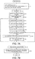
- FIG. 7A is a flowchart of the main processing.
- the main processing is processing executed after power supply is input to the wireless communication device 1 or after returning from a sleep.
- initializing processing is performed (S1). Specifically, 0 is set in an M counter memory 52q and an S counter memory 52r, 1 is set in the index memory 52t, and the retry packet data 52m is cleared.
- the LED 6 is turned off (S2).
- LED turning-off time setting processing is performed (S3).
- the LED turning-off time setting processing will be described.
- FIG. 7B is a flowchart of the LED turning-off time setting processing.
- a random value of three bits (0 to 7) is acquired, and a value obtained by adding 5 seconds to a value obtained by multiplying the random value by 0.5 seconds is set in the LED turning-off time memory 52x (S20). Accordingly, a random time within a range of 5.0 seconds to 8.5 seconds is stored in the LED turning-off time memory 52x.
- a known method such as a linear congruential method, is employed. After the processing of S20, the procedure returns to the main processing in FIG. 7A .
- FIG. 8 is a flowchart of the mode determination processing.
- the mode determination processing is processing in which a communication mode of the wireless communication device 1 is set.
- a communication mode of the subsequent mode memory 51b is set in the mode memory 52a (S30).
- the communication mode stored in the subsequent mode memory 51b on the basis of master-slave processing (which will be described below with FIG. 18B ) is set in the mode memory 52a as a current communication mode in accordance with the preceding communication state of the wireless communication device 1.
- the mode memory 52a is an undetermined value (S31).
- S31 when the wireless communication device 1 is in a case of factory shipment, or when the operation button 7 is subjected to a long press in the processing of S9 in FIG. 7A , which will be described below, "an undetermined value" is set in the subsequent mode memory 51b. In such a case, an undetermined value is also set in the mode memory 52a to which the value of the subsequent mode memory 51b in the processing of S30 is set. In such a case, there is a need to determine either communication mode of the master mode or the slave mode and set the determined mode in the mode memory 52a and the subsequent mode memory 51b.
- S31 master-slave
- S32 master-slave
- FIG. 9A is a flowchart of the MS tendency decision processing.
- the MS tendency decision processing is processing in which the appearance patterns P1 to P3 in the MS appearance pattern table 51c ( FIG. 5A ) are acquired in accordance with MIDI data input from the input terminal 3 and the acquired appearance patterns are set in the appearance pattern memory 52s.
- the appearance pattern P3 is set in the appearance pattern memory 52s as an initial value (S50). After the processing of S50, clocking starts using the RTC 55 (S51). After the processing of S51, it is confirmed whether there is MIDI data in data input from the input terminal 3 from starting of clocking in the processing of S51 (S52). In the processing of S52, when there is MIDI data in the data input from the input terminal 3 (S52: Yes), the appearance pattern P2 is set in the appearance pattern memory 52s (S53).
- the appearance patterns P1 to P3 to be set in the appearance pattern memory 52s are determined in accordance with data from the input terminal for 0.3 seconds.
- MIDI data is input from the input terminal 3 (S52)
- an instruction from the electronic musical instrument 100 is input, and it is judged that there are many opportunities for transmitting MIDI data from the wireless communication device 1.
- the appearance pattern P2 in which the master mode is preferentially set as a communication mode is set in the appearance pattern memory 52s.
- the appearance pattern P1 in which the master mode is set with top priority as a communication mode is set in the appearance pattern memory 52s.
- the master mode can be set as a communication mode with a high probability by setting the appearance patterns P1 and P2 in which the master mode is preferentially set as a communication mode in accordance with a case in which MIDI data is input from the input terminal and a case in which MIDI data is data related to synchronization. Therefore, MIDI data input from the input terminal 3 can be efficiently transmitted through the wireless module 5.
- mode setting processing is executed (S33).
- S33 mode setting processing
- FIG. 9B is a flowchart of the mode setting processing.
- the mode setting processing is processing in which the communication mode is determined based on the MS appearance pattern table 51c, the appearance patterns P1 to P3 set in the MS tendency decision processing, and the index memory 52t.
- the appearance patterns P1 to P3 corresponding to the appearance pattern memory 52s are acquired from the MS appearance pattern table 51c (S60). After the processing of S60, it is confirmed whether the value of the index memory 52t is larger than the number of modes of the communication modes stored in the appearance patterns P1 to P3 acquired in the processing of S60 (S61).
- a communication mode corresponding to the index memory 52t in the appearance patterns P1 to P3 acquired in the processing of S60 is acquired from the MS appearance pattern table 51c and set in the mode memory 52a (S63).
- the corresponding communication mode is the master mode (refer to FIG. 5A ). Therefore, the master mode is set in the mode memory 52a.
- 1 is added to the index memory 52t (S64), and the mode setting processing ends.
- the communication mode set in the foregoing MS tendency decision processing ( FIG. 9A ) based on the appearance patterns P1 to P3 is acquired from the MS appearance pattern table 51c and set in the mode memory 52a.
- the communication mode according to the value of the index memory 52t is acquired from the appearance patterns P1 to P3.
- the value of the index memory 52t changes from 1 in an ascending order. Therefore, the communication mode can be set in the mode memory 52a without disrupting an appearance frequency or a tendency of the master mode or the slave mode stored in the appearance patterns P1 to P3.
- FIG. 9C is a flowchart of the MS standby time setting processing.
- the MS standby time setting processing a random value of four bits (0 to 15) is acquired, and a value obtained by adding 3 seconds to a value obtained by multiplying the acquired random value by 0.2 seconds is set in the MS standby time memory 52u (S70). Accordingly, a random time within a range of 3 seconds to 6 seconds is stored in the MS standby time memory 52u.
- the MS standby time setting processing ends, and the procedure returns to the mode determination processing in FIG. 8 .
- a mode setting permission notification is transmitted to the other wireless communication device 1 (S41).
- This mode setting permission notification is the same as the mode setting permission notification for standing by for reception from the other wireless communication device 1 in S37 and S38. Further, after the processing of S41, the value of the mode memory 52a is set in the subsequent mode memory 51b in the foregoing processing of S39.
- a mode setting notification is transmitted to the other wireless communication device 1.
- the master mode is settled as a communication mode, and the master mode is set in the mode memory 52a and the subsequent mode memory 51b.
- the slave mode is set in the mode memory 52a in the processing of S33, in a case in which a mode setting notification from the other wireless communication device 1 is received, the slave mode is settled as a communication mode, and the slave mode is set in the mode memory 52a and the subsequent mode memory 51b. In addition, a mode setting permission notification is transmitted to the other wireless communication device 1.
- a different communication mode can be automatically set in each of the paired wireless communication devices 1 without providing an operation piece, a display, or the like for setting a communication mode for the wireless communication device 1.
- the same communication mode is not set in both the paired wireless communication devices 1, a situation in which wireless communication cannot be performed between the paired wireless communication devices 1 can be prevented.
- a probability that a different communication mode is set in each of the paired wireless communication devices 1 can be improved by executing the processing of S33 again, resetting a communication mode in the mode memory 52a, and then executing an inquiry for mode setting in the processing of S36 thereafter again. Therefore, a communication mode can be quickly set in the paired wireless communication devices 1.
- a timing at which standby processing in S38 and S42 continues can be staggered between the paired wireless communication devices 1. Also this case, the probability that a different communication mode is set in each of the paired wireless communication devices 1 can be improved.
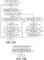
- FIG. 10A is a flowchart of the master LED processing.
- the master LED processing is processing in which turning-on and turning-off of the LED 6 are controlled when the communication mode is the master mode.
- the master LED processing first, it is confirmed whether the value of the mode memory 52a is the master mode (S75). In the processing of S75, when the value of the mode memory 52a is the master mode (S75: Yes), the elapsed time from the preceding master LED processing acquired from the RTC 55 is added to the time counter 52v (S76).
- FIG. 10B is a flowchart of the LED turning-on time setting processing.
- a random value of three bits (0 to 7) is acquired, and a value obtained by adding 0.5 seconds to a value obtained by multiplying the random value by 0.1 seconds is set in the LED turning-on time memory 52w (S90). Accordingly, a random time within a range of 0.5 seconds to 1.2 seconds is stored in the LED turning-on time memory 52w. After the processing of S90, the LED turning-on time setting processing ends.
- the master LED processing ends. Processing of turning on the LED 6 in the wireless communication device 1 on the slave mode side will be described below with FIG. 20A .
- turning-on and turning-off of the LED 6 are controlled on the basis of the LED turning-on time memory 52w and the LED turning-off time memory 52x, and the state thereof being turned on or turned off is transmitted to the other wireless communication device 1 on the slave mode side via the control data memory 52n.
- Turning-on and turning-off of the LED 6 are performed in accordance with the received state of the LED being turned on or turned off in the other wireless communication device 1 on the slave mode side, and this will be described below in detail.
- the state of the LED 6 being turned on or turned off in the wireless communication device 1 on the master mode side and the state of the LED 6 being turned on or turned off in the other wireless communication device 1 on the slave mode side can be synchronized. Accordingly, even when there is a plurality of paired wireless communication devices 1, a cycle of turning on and turning off the LED 6 can differ between the paired wireless communication devices 1. Therefore, the paired wireless communication devices 1 can be easily identified. Accordingly, a pairing counterpart can be easily identified. Since identification of the paired wireless communication devices 1 can be realized with only the LED 6, there is no need for the wireless communication device 1 to be provided with a display for displaying character strings such as names of the pair. Accordingly, manufacturing costs of the wireless communication device 1 can be reduced, and the wireless communication device 1 can be miniaturized.
- each of the paired wireless communication devices 1 can have a different cycle of turning-on and turning-off. Therefore, the paired wireless communication devices 1 can be more easily identified.
- a time shorter than the LED turning-off time memory 52x is set in the LED turning-on time memory 52w. Accordingly, the turning-on time of the LED 6 can be shortened. Therefore, wearing out of the battery B can be curbed, and the battery B can have a long lifespan.
- the turning-on time and the turning-off time are set in the LED turning-on time memory 52w and the LED turning-off time memory 52x in only the wireless communication device 1 on the master mode side. Therefore, a load on the processing in the wireless communication device 1 on the slave mode side can be reduced.
- FIG. 11 is a flowchart of the communication processing.
- the communication processing is processing in which MIDI data is transmitted and received by the communication A and the communication B.
- the communication A transmission FIFO 52d is set as a transmission FIFO
- the communication A reception FIFO 52e is set as a reception FIFO
- the reading position of the input data FIFO 52b is set for the communication A (S100).
- the reading position of the input data FIFO 52b is provided in each of the communication A and the communication B, but the reading position of the communication A thereof is selected in the processing of S100, and the reading position is referred to in S101 of transmission packet generation processing (which will be described below).
- S101 transmission packet generation processing
- FIG. 12A is a flowchart of the transmission packet generation processing.
- the transmission packet generation processing is processing of generating a transmission packet for performing transmission from MIDI data stored in the input data FIFO 52b in MIDI input interruption processing (which will be described below with FIG. 12B ) to the other wireless communication device 1.
- the transmission packet generation processing first, it is confirmed whether there is MIDI data at the reading position of the input data FIFO 52b (S120).
- the reading position of the input data FIFO 52b is provided in each of the communication A and the communication B, but it is confirmed whether or not MIDI data is present in the input data FIFO 52b at the reading position thereof set in the processing of S100 or in the processing of S106 (which will be described below).
- "the reading position" indicates the reading position set in the processing of S100 immediately before the transmission packet generation processing is executed or the processing of S106 (which will be described below).
- the processing of S120 when there is MIDI data at the reading position of the input data FIFO 52b (S120: Yes), the MIDI data is acquired (S121).
- the packet generated in the processing of S123 is added to the transmission FIFO (S124).
- the reading position of the input data FIFO 52b is caused to proceed by 1 (S125), and the processing of S120 and thereafter is repeated.
- the MIDI input interruption processing is interruption processing executed when data is input from the input terminal 3, and it is processing in which MIDI data input from the input terminal 3 is added to the input data FIFO 52b.
- MIDI input interruption processing first, it is confirmed whether there is MIDI data input from the input terminal 3 (S130). In the processing of S130, when there is MIDI data input from the input terminal 3 (S130: Yes), 1 is added to the M counter memory 52q (S131).
- MIDI data in S130 is data related to MIDI synchronization (S132). Similar to the foregoing processing of S54 in FIG. 7A , data related to MIDI synchronization includes "a MIDI timing clock (F8H)" or "a MIDI time code quarter frame (F1H)" as an example.
- F8H MIDI timing clock
- F1H MIDI time code quarter frame
- MIDI data When MIDI data is input from the input terminal 3, the MIDI data is transmitted through the wireless module 5. That is, if a larger amount of MIDI data is input from the input terminal 3, the transmission frequency through the wireless module 5 increases. In such a case, a subsequent communication mode can be preferentially changed to the master mode in master-slave decision processing (which will be described below with FIG. 18B ) by performing addition to the M counter memory 52q.
- the data related to MIDI synchronization is data related to tempo
- the subsequent communication mode can be more preferentially changed to the master mode by further performing addition to the M counter memory 52q.
- MIDI data acquired in the processing of S130 is added to the input data FIFO 52b after an ID is applied thereto (S134), and the processing of S130 and thereafter is repeated.
- the ID applied in the processing of S134 is a number which is uniquely allocated to each piece of MIDI data input to the input terminal 3. More specifically, integers in an ascending order are allocated as IDs in an order of arrival of MIDI data input to the input terminal 3.
- the communication A packet transmission registration processing (S102) is performed.
- the communication A packet transmission registration processing will be described with reference to FIG. 13 .
- FIG. 13 is a flowchart of the communication A packet transmission registration processing.
- the communication A packet transmission registration processing first, it is confirmed whether there is a packet at the reading position of the transmission FIFO (S140).
- the packet is acquired (S141).
- the ID of the packet acquired in the processing of S41 is larger than the transmitted ID memory 52i (S142).
- the ID of the packet received from the other wireless communication device 1 and the foregoing control data such as information of turning-on and turning-off of the LED 6 stored in the control data memory 52n can be transmitted to the other wireless communication device 1 via the communication A.
- the other wireless communication device 1 it is possible to confirm that the transmitted MIDI data has reliably arrived by confirming the reply ID of the received packet.
- the information of turning-on, turning-off, or the like of the LED 6 can be executed on the basis of the control data of the received packet.
- the packet in which embedment has been performed in S143 is registered as a transmission target of the communication A (S144).
- the packet registered as a transmission target of the communication A is transmitted to the other wireless communication device 1 every 7.5 milliseconds.
- the value of the received ID memory 52j is set as the reply ID
- the value of the control data memory 52n is set as control data
- a packet in which an empty value is set as actual data is generated (S147).
- the packet having no data generated in the processing of S148 is registered as a transmission target of the communication A (S148).
- the communication A packet transmission registration processing ends.
- communication A reception packet processing (S103) is performed.
- S103 communication A reception packet processing
- FIGS. 14 and 15 the communication A reception packet processing and the interruption processing performed when a packet is received by the communication A will be described.
- the received packet is added to the reception FIFO in the interruption processing.
- the packet added to the reception FIFO in the communication A reception interruption processing is processed in the communication A reception packet processing in FIG. 14 .
- FIG. 14 is a flowchart of the communication A reception packet processing.
- the communication A reception packet processing first, it is confirmed whether there is a packet at the reading position of the reception FIFO (S160).
- the packet is acquired (S161).
- S162 After the processing of S161, it is confirmed whether the kind of the acquired packet is mode switching (S162).
- there are provided two kinds of packets such as a packet storing the foregoing MIDI data and a packet related to mode switching transmitted and received for switching between the communication modes.
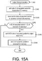
- FIG. 15A is a flowchart of the output data processing.
- the reply ID of the acquired packet is set in the transmitted ID memory 52i (S180). Accordingly, the ID of a packet transmitted to the other wireless communication device 1 (a packet processed by the other wireless communication device 1), that is, a packet which has been transmitted is set in the transmitted ID memory 52i.
- control data of the acquired packet is set in the received control data memory 52p (S181). After the processing of S181, it is confirmed whether the ID of the acquired packet is larger than the ID of the received ID memory 52j (S182).
- the acquired packet is added to the communication A transmission FIFO 52d (S168), and an inverted mode of the communication mode stored in the acquired packet is set in the subsequent mode memory 51b (S169).
- the slave mode is set in the subsequent mode memory 51b.
- the master mode is set in the subsequent mode memory 51b.
- the communication mode set in the mode switching packet set in the master-slave decision processing (which will be described below with FIG. 18B ) is set in the subsequent mode memory 51b.
- MIDI data output processing (S104) is executed.
- S104 MIDI data output processing
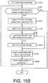
- FIG. 15B is a flowchart of the MIDI data output processing.
- the MIDI data output processing is processing in which MIDI data stored in the output data FIFO 52c is output to the output terminal 8.
- MIDI data output processing first, it is confirmed whether there is MIDI data at the reading position of the output data FIFO 52c (S190).
- the MIDI data is received through the wireless module 5. That is, if a larger amount of MIDI data is output to the output terminal 8, the reception frequency through the wireless module 5 increases. In such a case, the communication mode can be preferentially changed to the slave mode in the master-slave decision processing (which will be described below with FIG. 18B ) by performing addition to the S counter memory 52r.
- output MIDI data includes data related to MIDI synchronization
- the communication mode can be more preferentially changed to the slave mode by further performing addition to the S counter memory 52r.
- the frequency used for communication by the communication A is acquired and is set as a frequency to be used for communication by the communication B (S105).
- the frequency used for wireless communication is timely (for example, each time of communication, regularly) changed. Accordingly, even if an other communication device using a frequency similar to the frequency used for the communication A is operated in the vicinity of the wireless communication device 1, wireless communication by the communication A can be performed without having crosstalk with an other communication device.
- wireless communication by the communication B can be achieved without having crosstalk with an other communication device similar to the communication A by using the same frequency as that in the immediately preceding communication A.
- the communication B transmission FIFO 52f is set as a transmission FIFO
- the communication B reception FIFO 52g is set as a reception FIFO
- the reading position of the input data FIFO 52b is set for the communication B (S106).
- the foregoing transmission packet generation processing of the S101 in FIG. 12A is performed. Accordingly, a packet transmitted by the communication B is added to the transmission FIFO, that is, the communication B transmission FIFO 52f.
- the reading position referred to in the input data FIFO 52b is individually provided in the communication A and the communication B. Accordingly, in the transmission packet generation processing individually executed in the communication A and the communication B, multiple packets can be prepared from the same input data FIFO 52b and can be transmitted to the other wireless communication device 1. Moreover, in the transmission packet generation processing, MIDI data of the IDs and thereafter stored in the transmitted ID memory 52i in the processing of S122, that is, the packets based on MIDI data which has been transmitted is not added to the transmission FIFO. Therefore, retransmission of MIDI data which has been transmitted is curbed. Accordingly, execution of useless wireless communication can be curbed.
- the value of the mode memory 52a is confirmed (S107).
- S107 when the value of the mode memory 52a is the master mode (S107: master mode), it is acquired whether there is a spare time of 2 milliseconds or longer before a subsequent communication A (S108). As described above, communication by the communication A is performed every 7.5 milliseconds. Therefore, in the processing of S108, it is acquired whether or not there are 2 milliseconds or longer from a current time until the subsequent communication A is executed.
- FIGS. 16 and 17 are flowcharts of the communication B packet transmission/reception processing.
- the communication B packet transmission/reception processing first, it is confirmed whether the retry flag 52k has been turned on (S200, FIG. 16 ).
- S200 when the retry flag 52k is turned off (S200: No), packet transmission is not being retried in the processing of S214 and S215 ( FIG. 16 , which will be described below). Therefore, it is confirmed whether there is a packet in the reading position of the transmission FIFO (S201).
- the packet is acquired (S202). After the processing of S202, it is confirmed whether the ID of the packet acquired in the processing of S202 is larger than the ID of the transmitted ID memory (S203). In the processing of S203, when the ID of the acquired packet is larger than the ID of the transmitted ID memory (S203: Yes), the acquired packet is set as a packet (transmission target) by the communication B (S204). In the processing of S203, when the ID of the acquired packet is equal to or smaller than the ID of the transmitted ID memory (S203: No), the processing of S204 is skipped. After the processing of S203 and S204, the reading position of the transmission FIFO is caused to proceed by 1 (S205).
- data is embedded into the packet (transmission target) ( FIG. 17 , S206).
- the value of the received ID memory 52j is set as a reply ID of a packet (transmission target)
- the value of the control data memory 52n is set as control data of the packet (transmission target). Accordingly, the ID of the packet received from the other wireless communication device 1 and the foregoing control data such as information of turning-on and turning-off of the LED 6 stored in the control data memory 52n can be transmitted to the other wireless communication device 1 via the communication B.
- the packet (transmission target) is transmitted to the other wireless communication device 1 using the communication B (S207).
- transmission of the packet in the processing of S207 is received by the communication B, and it is confirmed whether a packet from the other wireless communication device 1 has been received (S208).
- the packet included in the retry packet data 52m is set as the packet (transmission target) (S215), and the processing of S206 in FIG. 17 and thereafter is executed. Accordingly, in the processing of S211 to S213 in FIG. 17 , a packet which is judged to fail to be transmitted can be retransmitted to the other wireless communication device 1. When the retransmission also fails, retransmission in the processing of S211 to S213 in FIG. 17 is performed again. Therefore, the packet of the transmission FIFO can be reliably transmitted to the other wireless communication device 1.
- the packet when a packet having no data fails to be transmitted, the packet is not retransmitted. Accordingly, a packet having no data is not repeatedly retransmitted. Therefore, when a packet is added to the transmission FIFO, the packet can be quickly transmitted to the other wireless communication device 1 on the slave mode side.
- communication B reception packet processing (S111) is executed.
- the communication B reception packet processing will be described.
- FIG. 18A is a flowchart of the communication B reception packet processing.
- the communication B reception packet processing first, it is confirmed whether there is a packet at the reading position of the reception FIFO (S230).
- S230 when there is a packet at the reading position of the reception FIFO (S230: Yes), the packet is acquired (S231).
- the output data processing of S163 ( FIG. 15A ) is executed.
- the reading position of the reception FIFO is caused to proceed by 1 (S232), and the processing of S230 and thereafter is repeated.
- FIG. 18B is a flowchart of the master-slave decision processing.
- the master-slave decision processing is processing in which the communication mode is determined on the basis of the values of the M counter memory 52q and of the S counter memory 52r set in the MIDI input interruption processing in FIG. 12B and the MIDI data output processing in FIG. 15B and the foregoing mode switching packet is generated on the basis of the communication mode.
- the master-slave decision processing first, it is confirmed whether the value of the S counter memory 52r is larger than a value obtained by multiplying the value of the M counter memory 52q by 1.5 (S240).
- S240 when the value of the S counter memory 52r is larger than a value obtained by multiplying the value of the M counter memory 52q by 1.5 (S240: Yes), the value of the S counter memory 52r is sufficiently larger than the value of the M counter memory 52q, that is, an output of MIDI data to the output terminal 8 is sufficiently larger than an input of MIDI data from the input terminal 3. Therefore, the communication mode is ought to be the slave mode in this case.
- the value of the subsequent mode memory 51b is the slave mode (S244).
- the value of the subsequent mode memory 51b is the slave mode (S244: Yes)
- a mode switching packet indicating that the communication mode is changed to the master mode is added to the communication A transmission FIFO 52d (S245).
- the processing of S245 is skipped.
- the communication mode is changed from the communication mode determined in the mode determination processing in FIG. 5 on the basis of the value of the M counter memory 52q and the value of the S counter memory 52r, that is, an input of MIDI data from the input terminal 3 and an output of MIDI data to the output terminal 8. Accordingly, when the power supply of the wireless communication device 1 is turned on next time or when returning from a sleep, the communication mode is reset in accordance with the current communication circumstances of the wireless communication device 1. Therefore, the efficiency of wireless communication of the wireless communication device 1 can be improved.
- FIG. 19 is a flowchart of the communication B reception interruption processing.
- the communication B reception interruption processing is interruption processing executed when reception by the communication B is performed. In the communication B reception interruption processing, first, it is confirmed whether the value of the mode memory 52a is the slave mode (S250).
- a packet stored in the reply buffer 52h is transmitted by the communication B (S241).
- the packet stored in the reply buffer 52h is a packet stored in the reply buffer 52h in the processing of S253 to S261 (which will be described below) in the preceding communication B reception interruption processing.
- the packet received by the communication B is added to the reception FIFO (S252).
- the packet transmitted in the processing of S251 in the subsequent communication B reception interruption processing is set in the reply buffer 52h.
- the packet is confirmed whether there is a packet at the reading position of the transmission FIFO (S253).
- the packet is acquired (S254).
- the processing of S254 it is confirmed whether the ID of the packet acquired in the processing of S254 is larger than the transmitted ID memory 52i (S255).
- a packet having no data is generated (S258). Specifically, the value of the received ID memory 52j is set as the reply ID, the value of the control data memory 52n is set as control data, and a packet in which an empty value is set as actual data is generated. Further, after the processing of S257 and S258, the generated packet is saved in the reply buffer 52h (S259) in preparation for the transmission processing of S252 in the subsequent communication B reception interruption processing.
- slave LED processing (S7) is executed.
- S7 slave LED processing
- FIG. 20A is a flowchart of the slave LED processing.
- the slave LED processing first, it is confirmed whether the value of the mode memory 52a is the slave mode (S270).
- S270 when the value of the mode memory 52a is the slave mode (S270: Yes), in accordance with information of turning-on and turning-off of the LED 6 in the received control data memory 52p, the LED 6 is turned on or turned off (S271).
- S270 when the value of the mode memory 52a is the master mode (S270: No) or after the processing of S271, the slave LED processing ends.
- a state of turning-on or turning-off of the LED 6 set in the wireless communication device 1 on the master mode side in the master LED processing of S5 is reflected in the wireless communication device 1 on the slave mode side. Accordingly, turning-on or turning-off of the LED 6 of the paired wireless communication devices 1 can be synchronized. Therefore, the paired wireless communication devices 1 can be easily identified.
- an instruction of turning-on or turning-off of the LED 6 from the wireless communication device 1 on the master mode side to the wireless communication device 1 on the slave mode side is included in the received control data memory 52p, that is, control data of a packet for transmitting MIDI data, and it is transmitted. Accordingly, there is no need to transmit a packet by wireless communication in accordance with only an instruction of turning-on or turning-off of the LED 6. Therefore, increase in amount of communication in wireless communication can be curbed.
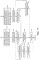
- FIG. 20B is a flowchart of the battery control processing.
- the battery control processing is processing in which the battery switch 10 is controlled in accordance with an input of data from the input terminal 3 and the communication state of the wireless module 5.
- the battery control processing first, it is confirmed whether data has been input from the input terminal 3 or data is being transmitted through the wireless module 5 (S280).
- the battery switch 10 is switched to the battery B side (that is, the Vb' line 31a in FIG. 6 ) (S281).
- the battery switch 10 is switched to the input terminal 3 side (that is, the Vm_in line 3a in FIG. 6 ) (S282).
- the battery control processing ends.
- the control part 4 consumes a small amount of electric power.
- the control part 4 consumes a small amount of electric power.
- the control part 4 consumes a large amount of electric power.
- data is transmitted through the wireless module 5, there is a need to output electromagnetic waves through the wireless module 5. Therefore, even in this case, the control part 4 consumes a large amount of electric power.
- stable electric power from the battery B is supplied to the control part 4 by switching the battery switch 10 to the battery B side. Therefore, the control part 4 can be stably operated, and processing of data from the input terminal 3 or transmission through the wireless module 5 can be quickly performed without causing latency.
- a wireless communication device 200 of a second embodiment will be described.
- the LED 6 is turned on or turned off at random time intervals.
- a sequence which is a combination of a series of patterns of turning-on or turning-off of the LED 6 is set, and turning-on or turning-off of the LED 6 is controlled on the basis of the sequence.
- the same reference signs are applied to the same portions as those of the foregoing first embodiment, and description thereof will be omitted.
- FIG. 21 is a block diagram illustrating an electrical configuration of the wireless communication device 200 according to the second embodiment.
- the LED 6 in the wireless communication device 200 is configured to have a red LED 6a which is turned on in red and a green LED 6b which is turned on in green.
- FIG. 22A is a view schematically illustrating the RAM 52 according to the second embodiment.
- the LED turning-on time memory 52w of the first embodiment is omitted, and an LED table 52y, an LED sequence memory 52z, and an LED step memory 52aa are provided instead thereof.
- the LED table 52y is a data table storing a plurality of sequences which are combinations of a series of patterns of turning-on or turning-off of the LED 6.
- FIG. 22B the LED table 52y will be described.
- FIG. 22B is a view schematically illustrating the LED table 52y.
- the LED table 52y stores a plurality of sequences (which will be indicated as “SEQ” in the diagram), and the sequences are provided with “a step (which will be indicated as “STEP” in the diagram)” indicating a specific operation of the LED.
- the step is configured to have a combination of a target LED 6 (a pattern of turning-on colors of the red LED 6a or the green LED 6b), an operation with respect to the target LED 6 (a flickering pattern of turning-on or turning-off), and a continuation time of the operation.
- Each sequence is provided with a plurality of such steps. Accordingly, a form of turning-on or turning-off of the LED 6 in each sequence is set.
- the LED sequence memory 52z stores a sequence in the LED table 52y being processed
- the LED step memory 52aa stores a step in the LED table 52y being processed.
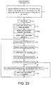
- FIG. 23 is a flowchart of the main processing according to the second embodiment.
- 1 is set in the LED sequence memory 52z and the LED step memory 52aa in addition to the M counter memory 52q, the S counter memory 52r, the index memory 52t, the retry packet data 52m, and initializing.
- sequence pattern preparation processing (S300) is performed between the LED turning-off time setting processing of S3 and the mode determination processing of S4.
- sequence pattern preparation processing will be described.
- FIG. 24A is a flowchart of the sequence pattern preparation processing.
- a random value of three bits (0 to 7) is acquired, and a value obtained by adding 1 to the acquired random value is set as a largest sequence number (S301).
- S301 a value obtained by adding 1 to the acquired random value is set as a largest sequence number (S301).
- S301 a counter variable M indicating a sequence
- a random value of 1 bit (0, 1) is acquired, and the acquired random value is confirmed (S305).
- the red LED 6a is set as the target LED (S306).
- the green LED 6b is set as the target LED (S307).
- LED turning-on setting processing (S308) is executed.
- LED turning-on setting processing will be described.
- FIG. 24B is a flowchart of the LED turning-on setting processing.
- the LED turning-on setting processing first, a random value of three bits (0 to 7) is acquired, and a value obtained by adding 0.5 seconds to a value obtained by multiplying the acquired random value by 0.1 seconds is set as the turning-on time (S320).
- the target LED set in the processing of S307 and S308 in the sequence pattern preparation processing in FIG. 24A and the turning-on time set in the processing of S320 are individually set for "LED” and "time" of an Nth step in an Mth sequence in the LED table 52y.
- "turning-on” is set for "operation" of the same step in the same sequence (S321). Accordingly, a step of turning on the red LED 6a or the green LED 6b is prepared. After the processing of S321, the LED turning-on setting processing ends.
- FIG. 24C is a flowchart of the LED turning-off setting processing.
- the LED turning-off setting processing first, a random value of three bits (0 to 7) is acquired, and a value obtained by adding 0.5 seconds to a value obtained by multiplying the acquired random value by 0.1 seconds is set as a turning-off time (S330).
- the target LED set in the processing of S307 and S308 in the sequence pattern preparation processing in FIG. 24A and the turning-off time set in the processing of S330 are individually set for "LED” and "time" of the Nth step in the Mth sequence in the LED table 52y.
- "turning-off” is set for "operation" of the same step in the same sequence (S331). Accordingly, a step of turning off the red LED 6a or the green LED 6b is prepared.
- the LED turning-off setting processing ends.
- FIG. 25 is a flowchart of the master LED processing according to the second embodiment.
- the master LED processing first, it is confirmed whether the value of the mode memory 52a is the master mode (S340).
- the elapsed time acquired from the RTC 55 in the preceding master LED processing is added to the time counter 52v (S342), and it is confirmed whether the LED 6 has been turned on or turned off in accordance with the sequence stored in the LED table 52y (S343).
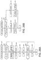
- FIG. 26A is a flowchart of the sequence updating processing.
- the sequence updating processing first, it is confirmed whether the counter variable N is larger than the largest step number of the Mth sequence in the LED table 52y (S360).
- S360 when the counter variable N is larger than the largest step number of the Mth sequence in the LED table 52y (S360: Yes), this denotes an intermission between a sequence and another sequence. Therefore, for the moment, in order to turn off the LED 6 based on the value of the LED turning-off time memory 52x, first, turning-on or turning-off of the LED 6 according to the LED table 52y is halted (S361), 0 is set in the time counter 52v (S362).
- FIG. 26B is a flowchart of the all LED turning-off processing.
- the all LED turning-off processing first, it is confirmed whether the time of the time counter 52v is smaller than the time of the LED turning-off time memory 52x (S370).
- the value of the counter variable M is set in the LED sequence memory 52z, and the value of the counter variable N is set in the LED step memory 52aa (S351).
- the LED table 52y stores the sequences in which the red LED 6a or the green LED 6b to be turned on is randomly selected and the turning-on time or the turning-off time thereof is also randomly set.
- the LED 6 is turned on or turned off on the basis of the sequence. Accordingly, the turning-on color, the turning-on time, or the turning-off time of the LED 6 can be changed in detail. Therefore, the paired wireless communication devices 200 can be easily identified.
- the LED 6 is turned off based on the LED turning-off time memory 52x between turning-on or turning-off of the LED 6 based on the sequence of 1 in the LED table 52y and turning-on or turning-off of the LED 6 based on the next sequence in the LED table 52y.
- a random time is also set in the LED turning-off time memory 52x. Therefore, the paired wireless communication devices 200 can be more easily identified in accordance with a cycle of turning-on or turning-off of the LED 6 based on the sequence and turning-off of the LED 6 based on the LED turning-off time memory 52x.
- the battery switch 10 when data is input from the input terminal 3 or data is being transmitted through the wireless module 5, the battery switch 10 is switched to the battery B side.
- conditions for switching the battery switch 10 are not limited thereto.
- the battery switch 10 may be switched to the battery B side only when data is input from the input terminal 3, or the battery switch 10 may be switched to the battery B side only when data is being transmitted through the wireless module 5.
- the battery switch 10 may be switched on the basis of a voltage input from the input terminal 3.
- a voltage from the input terminal 3 is sufficiently larger than 2.0 V, for example, that is a lowest operation voltage of the CPU 50 (S400: Yes)
- the battery switch 10 is switched to the battery B side (S402), and no data is input from the input terminal 3.
- the battery switch 10 is switched to the input terminal 3 side (S403).
- the battery switch 10 is switched to the battery B side at all times (S402). Accordingly, when a small voltage is input from the input terminal 3 so that the CPU 50 cannot be stably operated only with the input terminal 3, power is supplied from the battery B. Therefore, even in such a case, the CPU 50, that is, the wireless communication device 1 or 200 can be stably operated.
- the battery switch 10 may be switched on the basis of a voltage from the battery B.
- a voltage from the battery B drops, for example, when the voltage drops to 2.5 V close to 2.0 V that is the lowest operation voltage of the CPU 50, first, a warning such as flickering of the LED 6 in a certain cycle is displayed. Accordingly, a user can be made recognize that the battery B is wearing out.
- the battery switch 10 is switched to the input terminal 3 side. Accordingly, a situation in which the CPU 50 becomes inoperative is avoided, and the control part 4 can continue to be operated.
- MIDI data can be acquired from the input terminal 3, and the MIDI data can be subjected to wireless communication to the counterpart wireless communication device 1 or 200 via the wireless module 5.
- electric power supplied from the battery B to the output terminal 8 becomes unstable. Therefore, electric power supplied to the output terminal 8 by the supply part 11 may be blocked, and operation of transmitting MIDI data acquired from the counterpart wireless communication device 1 or 200 to the output terminal 8 via the wireless module 5 may be halted.
- display of a warning by the foregoing LED 6 may be omitted.
- the battery switch 10 may also switch between on and off according to whether the communication mode is the master mode or the slave mode. For example, as in FIG. 27B , when the value of the mode memory 52a is the master mode (S450: "master mode"), the battery switch 10 is switched to the battery B side (S452). Accordingly, processing of MIDI data input from the input terminal 3 or transmission through the wireless module 5 can be performed without causing latency with respect to the wireless communication device 1 or 200 on the master mode side having a high frequency of transmission by supplying power from the battery B at all times.
- the value of the mode memory 52a is the slave mode (S450: "slave mode")
- the battery switch 10 when data is input from the input terminal 3 or data is being transmitted through the wireless module 5 (S451: Yes), the battery switch 10 is switched to the battery B side (S452), and no data is input from the input terminal 3.
- the battery switch 10 When no data is transmitted through the wireless module 5 (S451: No), the battery switch 10 is switched to the input terminal 3 side (S453).
- the wireless communication devices 1 or 200 on the slave mode side basically stands by for transmission from the master mode side. Therefore, wearing out of the battery B can be better curbed by supplying power from the battery B on the basis of an input from the input terminal 3 or transmission through the wireless module 5.
- the master mode and the slave mode are set in each of two wireless communication devices 1 or 200, but the embodiments are not limited thereto.
- One wireless communication device 1 of the master mode and two or more wireless communication devices 1 or 200 of the slave mode may be configured to perform wireless communication.
- a turning-on instruction or a turning-off instruction of the LED 6 is set in the control data memory 52n, and the turning-on instruction or a turning-off instruction is set in control data within a packet and transmitted to the counterpart wireless communication device 1 or 200 together with MIDI data.
- a form of transmitting a turning-on instruction or a turning-off instruction of the LED 6 to the counterpart wireless communication device 1 or 200 is not limited thereto.
- a turning-on instruction or a turning-off instruction of the LED 6 may be transmitted to the counterpart wireless communication device 1 or 200 based on a packet configured to have only a turning-on instruction or a turning-off instruction of the LED 6.
- the MIDI data output processing of S104 ( FIG. 15A ) is executed in the communication processing of S6 ( FIG. 11 ).
- the timing to execute the MIDI data output processing is not limited thereto.
- the MIDI data output processing may be executed in timer processing which is executed regularly (for example, every 100 milliseconds).
- the ID of the acquired packet is also set in the received ID memory 52j for the communication B.
- the embodiments are not necessarily limited thereto.
- the ID of the packet (transmission target) prepared in the processing of S206 may be set in the received ID memory 52j.
- the processing of S180 in the output data processing of S163 may be omitted.
- the received ID memory 52j can be quickly updated by setting the ID of the packet of the transmission target to the received ID memory 52j without waiting for the output data processing thereafter.
- the communication mode is determined on the basis of the appearance patterns P1 to P3 stored in the MS appearance pattern table 51c.
- a form of determining the communication mode is not limited thereto.
- the master mode and the slave mode may be made appear randomly and may be determined as a communication mode.
- one packet is configured to store one piece of MIDI data, but the embodiments are not necessarily limited thereto.
- One packet may store a plurality of pieces of MIDI data. At this time, the number of pieces of MIDI data to be stored in the packet may be added to the packet, or the number of pieces of MIDI data to be stored in the packet may be judged based on the data volume of MIDI data to be stored in the packet.
- the wireless communication device 1 or 200 is connected to the MIDI output terminal 102 and the MIDI input terminal 103 of the electronic musical instrument 100 via the input terminal 3 and the output terminal 8, but the embodiments are not limited thereto and may have a configuration in which the wireless communication device 1 or 200 is connected to an other communication terminal such as a USB in the electronic musical instrument 100 and MIDI data is input and output between the wireless communication device 1 or 200 and the electronic musical instrument 100 via a communication terminal.
- the wireless communication device 1 or 200 is not limited to being connected to the electronic musical instrument 100 and may be built into the electronic musical instrument 100, for example.
- communication is performed with an other wireless communication device 1 by wireless communication through the wireless module 5.
- a form of communicating with the other wireless communication device 1 is not limited to wireless communication.
- the wireless communication devices 1 may be connected to each other using a cable such as a LAN cable or a USB cable, and communication may be performed with the other wireless communication device 1 by wired communication using a LAN, a USB, or the like.
- the casings 2a and 2b are formed to be translucent, but the embodiments are not limited thereto.
- the casings 2a and 2b may be formed to be transparent.
- the casing 2a and the casing 2b may be formed to be opaque, and only a portion in the vicinity of the LED 6 of the casing 2a may be formed to be translucent or transparent.
Landscapes
- Engineering & Computer Science (AREA)
- Physics & Mathematics (AREA)
- Acoustics & Sound (AREA)
- Multimedia (AREA)
- Computer Networks & Wireless Communication (AREA)
- Electrophonic Musical Instruments (AREA)
Applications Claiming Priority (1)
| Application Number | Priority Date | Filing Date | Title |
|---|---|---|---|
| JP2019238893A JP2021107862A (ja) | 2019-12-27 | 2019-12-27 | 電子楽器用通信装置 |
Publications (2)
| Publication Number | Publication Date |
|---|---|
| EP3843084A1 true EP3843084A1 (de) | 2021-06-30 |
| EP3843084B1 EP3843084B1 (de) | 2022-05-04 |
Family
ID=73855120
Family Applications (1)
| Application Number | Title | Priority Date | Filing Date |
|---|---|---|---|
| EP20214640.3A Active EP3843084B1 (de) | 2019-12-27 | 2020-12-16 | Kommunikationsvorrichtung für ein elektronisches musikinstrument und elektrisches leistungsschaltverfahren dafür |
Country Status (4)
| Country | Link |
|---|---|
| US (1) | US11763788B2 (de) |
| EP (1) | EP3843084B1 (de) |
| JP (1) | JP2021107862A (de) |
| CN (1) | CN113053338B (de) |
Families Citing this family (5)
| Publication number | Priority date | Publication date | Assignee | Title |
|---|---|---|---|---|
| US11663999B2 (en) * | 2019-12-27 | 2023-05-30 | Roland Corporation | Wireless communication device, wireless communication method, and non-transitory computer-readable storage medium |
| JP2021107862A (ja) * | 2019-12-27 | 2021-07-29 | ローランド株式会社 | 電子楽器用通信装置 |
| JP7192831B2 (ja) * | 2020-06-24 | 2022-12-20 | カシオ計算機株式会社 | 演奏システム、端末装置、電子楽器、方法、およびプログラム |
| JP7655809B6 (ja) * | 2021-07-14 | 2025-06-19 | ローランド株式会社 | 制御装置、制御方法および制御システム |
| US20230114132A1 (en) * | 2021-10-08 | 2023-04-13 | Roland Corporation | Communication device and communication establishment method |
Citations (6)
| Publication number | Priority date | Publication date | Assignee | Title |
|---|---|---|---|---|
| JPS6325296B2 (de) | 1982-09-30 | 1988-05-25 | Shimadzu Corp | |
| US20150122111A1 (en) * | 2013-11-03 | 2015-05-07 | Miselu Inc | Adapter for music devices |
| US20160140943A1 (en) * | 2014-11-13 | 2016-05-19 | Integrated Technology and Entertainment Medium LLC | Midi devices and systems |
| CN205485500U (zh) * | 2016-03-29 | 2016-08-17 | 杭州随身教育科技有限公司 | 用于midi信号传输的转换装置 |
| US20170213533A1 (en) * | 2014-03-19 | 2017-07-27 | Quicco Sound Corporation | Dongle device for audio/music device |
| CN209401300U (zh) * | 2018-12-24 | 2019-09-17 | 华示(深圳)技术有限公司 | 一种基于蓝牙传输的midi信号转换装置 |
Family Cites Families (21)
| Publication number | Priority date | Publication date | Assignee | Title |
|---|---|---|---|---|
| JPH0237518Y2 (de) | 1986-07-29 | 1990-10-11 | ||
| US4945806A (en) * | 1989-01-19 | 1990-08-07 | Merrill Jr Raymond | Fiber optic musical instrument digital interface |
| JP3292492B2 (ja) * | 1992-01-17 | 2002-06-17 | ローランド株式会社 | 演奏情報処理装置 |
| US5700966A (en) * | 1994-12-27 | 1997-12-23 | Lamarra; Frank | Wireless remote channel-MIDI switching device |
| US5949012A (en) * | 1995-12-27 | 1999-09-07 | Kabushiki Kaisha Kawai Gakki Seisakusho | Electronic musical instrument and music performance information inputting apparatus capable of inputting various music performance information with simple operation |
| JP3587353B2 (ja) * | 1999-03-02 | 2004-11-10 | ヤマハ株式会社 | 電子楽器 |
| JP5200450B2 (ja) * | 2006-09-21 | 2013-06-05 | ヤマハ株式会社 | 電子鍵盤楽器 |
| US7786371B1 (en) * | 2006-11-14 | 2010-08-31 | Moates Eric L | Modular system for MIDI data |
| JP2011008311A (ja) * | 2009-06-23 | 2011-01-13 | Casio Computer Co Ltd | 入出力制御装置および電子楽器 |
| WO2014182936A2 (en) * | 2013-05-08 | 2014-11-13 | Maytech Music Systems Pty Ltd | Pedal board connection system for musical instruments |
| JP6444288B2 (ja) * | 2015-10-30 | 2018-12-26 | 株式会社ズーム | コントローラ、音源モジュール及び電子楽器 |
| JP6844114B2 (ja) * | 2016-03-23 | 2021-03-17 | カシオ計算機株式会社 | データ通信システム、端末装置、音響装置、データ通信方法、及びプログラム |
| JP6705374B2 (ja) * | 2016-12-29 | 2020-06-03 | ヤマハ株式会社 | 電子楽器および電子楽器システム |
| CN207558407U (zh) * | 2017-10-30 | 2018-06-29 | 丛林象(武汉)科技发展有限公司 | 打击乐器及多功能吉他 |
| CA3155543A1 (en) * | 2019-10-23 | 2021-04-29 | Thomas A. DOLAN | Wireless midi headset |
| JP2021107862A (ja) * | 2019-12-27 | 2021-07-29 | ローランド株式会社 | 電子楽器用通信装置 |
| US11663999B2 (en) * | 2019-12-27 | 2023-05-30 | Roland Corporation | Wireless communication device, wireless communication method, and non-transitory computer-readable storage medium |
| JP2021108421A (ja) * | 2019-12-27 | 2021-07-29 | ローランド株式会社 | 無線通信装置 |
| JP2022052901A (ja) * | 2020-09-24 | 2022-04-05 | ローランド株式会社 | 無線通信装置、電子機器および無線通信方法 |
| JP7685897B2 (ja) * | 2021-07-14 | 2025-06-04 | ローランド株式会社 | 制御装置、制御方法および制御システム |
| JP7655809B6 (ja) * | 2021-07-14 | 2025-06-19 | ローランド株式会社 | 制御装置、制御方法および制御システム |
-
2019
- 2019-12-27 JP JP2019238893A patent/JP2021107862A/ja active Pending
-
2020
- 2020-12-16 EP EP20214640.3A patent/EP3843084B1/de active Active
- 2020-12-22 CN CN202011533119.7A patent/CN113053338B/zh active Active
- 2020-12-24 US US17/133,677 patent/US11763788B2/en active Active
Patent Citations (6)
| Publication number | Priority date | Publication date | Assignee | Title |
|---|---|---|---|---|
| JPS6325296B2 (de) | 1982-09-30 | 1988-05-25 | Shimadzu Corp | |
| US20150122111A1 (en) * | 2013-11-03 | 2015-05-07 | Miselu Inc | Adapter for music devices |
| US20170213533A1 (en) * | 2014-03-19 | 2017-07-27 | Quicco Sound Corporation | Dongle device for audio/music device |
| US20160140943A1 (en) * | 2014-11-13 | 2016-05-19 | Integrated Technology and Entertainment Medium LLC | Midi devices and systems |
| CN205485500U (zh) * | 2016-03-29 | 2016-08-17 | 杭州随身教育科技有限公司 | 用于midi信号传输的转换装置 |
| CN209401300U (zh) * | 2018-12-24 | 2019-09-17 | 华示(深圳)技术有限公司 | 一种基于蓝牙传输的midi信号转换装置 |
Non-Patent Citations (2)
| Title |
|---|
| ANONYMOUS: "Owner's Manual WM-1 (Connected to MIDI Connector)", 1 January 2020 (2020-01-01), XP055802247, Retrieved from the Internet <URL:https://static.roland.com/assets/media/pdf/WM-1_WM-1D_eng01_W.pdf> [retrieved on 20210506] * |
| BYRON J: "MIDI Tutorial - learn.sparkfun.com", 28 February 2018 (2018-02-28), XP055802527, Retrieved from the Internet <URL:https://learn.sparkfun.com/tutorials/midi-tutorial/all> [retrieved on 20210507] * |
Also Published As
| Publication number | Publication date |
|---|---|
| CN113053338A (zh) | 2021-06-29 |
| JP2021107862A (ja) | 2021-07-29 |
| US11763788B2 (en) | 2023-09-19 |
| CN113053338B (zh) | 2025-07-15 |
| EP3843084B1 (de) | 2022-05-04 |
| US20210201867A1 (en) | 2021-07-01 |
Similar Documents
| Publication | Publication Date | Title |
|---|---|---|
| EP3843084B1 (de) | Kommunikationsvorrichtung für ein elektronisches musikinstrument und elektrisches leistungsschaltverfahren dafür | |
| US11663999B2 (en) | Wireless communication device, wireless communication method, and non-transitory computer-readable storage medium | |
| JPH10171583A (ja) | 位置検出装置およびその位置指示器 | |
| US4377804A (en) | Synchronous data transmission system utilizing AC power line | |
| CN108989079B (zh) | 无线通信系统和计算机可读介质 | |
| EP1746752A2 (de) | Kommunikationssteuerungsanlage zur Durchführung von Synchronisierungsverfahren sowie dazugehöriges Verfahren | |
| US4367387A (en) | Electronic controlled heat cooking apparatus | |
| JP2021108421A (ja) | 無線通信装置 | |
| EP3975597B1 (de) | Überschneidungsfreie drahtlose kommunikation von midi-daten | |
| EP0446864A2 (de) | Fernsteuervorrichtung mit Lernfunktion | |
| US20050048929A1 (en) | Communications system | |
| GB2293474A (en) | Controlling selection using a switch | |
| JP2021107860A (ja) | 無線通信装置および無線通信方法 | |
| JP2021107861A (ja) | 無線通信装置および無線通信方法 | |
| KR100194570B1 (ko) | 무선 페이저 | |
| JP6744980B2 (ja) | 電池モジュール、制御方法、プログラム、及び情報処理システム | |
| EP0510194A1 (de) | Terminal, datenprozessor, schalteinheit, schnittstelle und tastatur, die letzten drei mit den ersten zwei verbunden | |
| WO1999010992A1 (en) | Portable electronic information communication device and system, portable affinity announcing device and system, and program recording medium stored with affinity announcing program | |
| JP2005080140A (ja) | 赤外線リモートコントロールシステム、受光機、携帯電話端末及びそれに用いるワイヤレス操作方法 | |
| JP2000209687A (ja) | ワイヤレスマイクシステム、ワイヤレススピ―カ―システムと電子機器 | |
| KR102040905B1 (ko) | Lpwan을 이용한 센싱 데이터 전송방법 | |
| JP2004086812A (ja) | プログラム表示器 | |
| JP2025155252A (ja) | 電子式モータ保護リレー装置 | |
| JP6468730B2 (ja) | 無線通信システム | |
| JPH07283844A (ja) | 波形制御回路 |
Legal Events
| Date | Code | Title | Description |
|---|---|---|---|
| PUAI | Public reference made under article 153(3) epc to a published international application that has entered the european phase |
Free format text: ORIGINAL CODE: 0009012 |
|
| STAA | Information on the status of an ep patent application or granted ep patent |
Free format text: STATUS: THE APPLICATION HAS BEEN PUBLISHED |
|
| AK | Designated contracting states |
Kind code of ref document: A1 Designated state(s): AL AT BE BG CH CY CZ DE DK EE ES FI FR GB GR HR HU IE IS IT LI LT LU LV MC MK MT NL NO PL PT RO RS SE SI SK SM TR |
|
| STAA | Information on the status of an ep patent application or granted ep patent |
Free format text: STATUS: REQUEST FOR EXAMINATION WAS MADE |
|
| 17P | Request for examination filed |
Effective date: 20211202 |
|
| RBV | Designated contracting states (corrected) |
Designated state(s): AL AT BE BG CH CY CZ DE DK EE ES FI FR GB GR HR HU IE IS IT LI LT LU LV MC MK MT NL NO PL PT RO RS SE SI SK SM TR |
|
| GRAP | Despatch of communication of intention to grant a patent |
Free format text: ORIGINAL CODE: EPIDOSNIGR1 |
|
| STAA | Information on the status of an ep patent application or granted ep patent |
Free format text: STATUS: GRANT OF PATENT IS INTENDED |
|
| INTG | Intention to grant announced |
Effective date: 20220126 |
|
| RIC1 | Information provided on ipc code assigned before grant |
Ipc: G10H 1/00 20060101AFI20220114BHEP |
|
| GRAS | Grant fee paid |
Free format text: ORIGINAL CODE: EPIDOSNIGR3 |
|
| GRAA | (expected) grant |
Free format text: ORIGINAL CODE: 0009210 |
|
| STAA | Information on the status of an ep patent application or granted ep patent |
Free format text: STATUS: THE PATENT HAS BEEN GRANTED |
|
| AK | Designated contracting states |
Kind code of ref document: B1 Designated state(s): AL AT BE BG CH CY CZ DE DK EE ES FI FR GB GR HR HU IE IS IT LI LT LU LV MC MK MT NL NO PL PT RO RS SE SI SK SM TR |
|
| REG | Reference to a national code |
Ref country code: GB Ref legal event code: FG4D |
|
| REG | Reference to a national code |
Ref country code: CH Ref legal event code: EP |
|
| REG | Reference to a national code |
Ref country code: AT Ref legal event code: REF Ref document number: 1489957 Country of ref document: AT Kind code of ref document: T Effective date: 20220515 |
|
| REG | Reference to a national code |
Ref country code: IE Ref legal event code: FG4D Ref country code: DE Ref legal event code: R096 Ref document number: 602020003036 Country of ref document: DE |
|
| REG | Reference to a national code |
Ref country code: LT Ref legal event code: MG9D |
|
| REG | Reference to a national code |
Ref country code: NL Ref legal event code: MP Effective date: 20220504 |
|
| REG | Reference to a national code |
Ref country code: AT Ref legal event code: MK05 Ref document number: 1489957 Country of ref document: AT Kind code of ref document: T Effective date: 20220504 |
|
| PG25 | Lapsed in a contracting state [announced via postgrant information from national office to epo] |
Ref country code: SE Free format text: LAPSE BECAUSE OF FAILURE TO SUBMIT A TRANSLATION OF THE DESCRIPTION OR TO PAY THE FEE WITHIN THE PRESCRIBED TIME-LIMIT Effective date: 20220504 Ref country code: PT Free format text: LAPSE BECAUSE OF FAILURE TO SUBMIT A TRANSLATION OF THE DESCRIPTION OR TO PAY THE FEE WITHIN THE PRESCRIBED TIME-LIMIT Effective date: 20220905 Ref country code: NO Free format text: LAPSE BECAUSE OF FAILURE TO SUBMIT A TRANSLATION OF THE DESCRIPTION OR TO PAY THE FEE WITHIN THE PRESCRIBED TIME-LIMIT Effective date: 20220804 Ref country code: NL Free format text: LAPSE BECAUSE OF FAILURE TO SUBMIT A TRANSLATION OF THE DESCRIPTION OR TO PAY THE FEE WITHIN THE PRESCRIBED TIME-LIMIT Effective date: 20220504 Ref country code: LT Free format text: LAPSE BECAUSE OF FAILURE TO SUBMIT A TRANSLATION OF THE DESCRIPTION OR TO PAY THE FEE WITHIN THE PRESCRIBED TIME-LIMIT Effective date: 20220504 Ref country code: HR Free format text: LAPSE BECAUSE OF FAILURE TO SUBMIT A TRANSLATION OF THE DESCRIPTION OR TO PAY THE FEE WITHIN THE PRESCRIBED TIME-LIMIT Effective date: 20220504 Ref country code: GR Free format text: LAPSE BECAUSE OF FAILURE TO SUBMIT A TRANSLATION OF THE DESCRIPTION OR TO PAY THE FEE WITHIN THE PRESCRIBED TIME-LIMIT Effective date: 20220805 Ref country code: FI Free format text: LAPSE BECAUSE OF FAILURE TO SUBMIT A TRANSLATION OF THE DESCRIPTION OR TO PAY THE FEE WITHIN THE PRESCRIBED TIME-LIMIT Effective date: 20220504 Ref country code: BG Free format text: LAPSE BECAUSE OF FAILURE TO SUBMIT A TRANSLATION OF THE DESCRIPTION OR TO PAY THE FEE WITHIN THE PRESCRIBED TIME-LIMIT Effective date: 20220804 Ref country code: AT Free format text: LAPSE BECAUSE OF FAILURE TO SUBMIT A TRANSLATION OF THE DESCRIPTION OR TO PAY THE FEE WITHIN THE PRESCRIBED TIME-LIMIT Effective date: 20220504 |
|
| PG25 | Lapsed in a contracting state [announced via postgrant information from national office to epo] |
Ref country code: RS Free format text: LAPSE BECAUSE OF FAILURE TO SUBMIT A TRANSLATION OF THE DESCRIPTION OR TO PAY THE FEE WITHIN THE PRESCRIBED TIME-LIMIT Effective date: 20220504 Ref country code: PL Free format text: LAPSE BECAUSE OF FAILURE TO SUBMIT A TRANSLATION OF THE DESCRIPTION OR TO PAY THE FEE WITHIN THE PRESCRIBED TIME-LIMIT Effective date: 20220504 Ref country code: LV Free format text: LAPSE BECAUSE OF FAILURE TO SUBMIT A TRANSLATION OF THE DESCRIPTION OR TO PAY THE FEE WITHIN THE PRESCRIBED TIME-LIMIT Effective date: 20220504 Ref country code: IS Free format text: LAPSE BECAUSE OF FAILURE TO SUBMIT A TRANSLATION OF THE DESCRIPTION OR TO PAY THE FEE WITHIN THE PRESCRIBED TIME-LIMIT Effective date: 20220904 |
|
| PG25 | Lapsed in a contracting state [announced via postgrant information from national office to epo] |
Ref country code: SM Free format text: LAPSE BECAUSE OF FAILURE TO SUBMIT A TRANSLATION OF THE DESCRIPTION OR TO PAY THE FEE WITHIN THE PRESCRIBED TIME-LIMIT Effective date: 20220504 Ref country code: SK Free format text: LAPSE BECAUSE OF FAILURE TO SUBMIT A TRANSLATION OF THE DESCRIPTION OR TO PAY THE FEE WITHIN THE PRESCRIBED TIME-LIMIT Effective date: 20220504 Ref country code: RO Free format text: LAPSE BECAUSE OF FAILURE TO SUBMIT A TRANSLATION OF THE DESCRIPTION OR TO PAY THE FEE WITHIN THE PRESCRIBED TIME-LIMIT Effective date: 20220504 Ref country code: ES Free format text: LAPSE BECAUSE OF FAILURE TO SUBMIT A TRANSLATION OF THE DESCRIPTION OR TO PAY THE FEE WITHIN THE PRESCRIBED TIME-LIMIT Effective date: 20220504 Ref country code: EE Free format text: LAPSE BECAUSE OF FAILURE TO SUBMIT A TRANSLATION OF THE DESCRIPTION OR TO PAY THE FEE WITHIN THE PRESCRIBED TIME-LIMIT Effective date: 20220504 Ref country code: DK Free format text: LAPSE BECAUSE OF FAILURE TO SUBMIT A TRANSLATION OF THE DESCRIPTION OR TO PAY THE FEE WITHIN THE PRESCRIBED TIME-LIMIT Effective date: 20220504 Ref country code: CZ Free format text: LAPSE BECAUSE OF FAILURE TO SUBMIT A TRANSLATION OF THE DESCRIPTION OR TO PAY THE FEE WITHIN THE PRESCRIBED TIME-LIMIT Effective date: 20220504 |
|
| REG | Reference to a national code |
Ref country code: DE Ref legal event code: R097 Ref document number: 602020003036 Country of ref document: DE |
|
| PLBE | No opposition filed within time limit |
Free format text: ORIGINAL CODE: 0009261 |
|
| STAA | Information on the status of an ep patent application or granted ep patent |
Free format text: STATUS: NO OPPOSITION FILED WITHIN TIME LIMIT |
|
| PG25 | Lapsed in a contracting state [announced via postgrant information from national office to epo] |
Ref country code: AL Free format text: LAPSE BECAUSE OF FAILURE TO SUBMIT A TRANSLATION OF THE DESCRIPTION OR TO PAY THE FEE WITHIN THE PRESCRIBED TIME-LIMIT Effective date: 20220504 |
|
| 26N | No opposition filed |
Effective date: 20230207 |
|
| PG25 | Lapsed in a contracting state [announced via postgrant information from national office to epo] |
Ref country code: SI Free format text: LAPSE BECAUSE OF FAILURE TO SUBMIT A TRANSLATION OF THE DESCRIPTION OR TO PAY THE FEE WITHIN THE PRESCRIBED TIME-LIMIT Effective date: 20220504 |
|
| P01 | Opt-out of the competence of the unified patent court (upc) registered |
Effective date: 20230509 |
|
| REG | Reference to a national code |
Ref country code: BE Ref legal event code: MM Effective date: 20221231 |
|
| PG25 | Lapsed in a contracting state [announced via postgrant information from national office to epo] |
Ref country code: LU Free format text: LAPSE BECAUSE OF NON-PAYMENT OF DUE FEES Effective date: 20221216 |
|
| PG25 | Lapsed in a contracting state [announced via postgrant information from national office to epo] |
Ref country code: IE Free format text: LAPSE BECAUSE OF NON-PAYMENT OF DUE FEES Effective date: 20221216 |
|
| PG25 | Lapsed in a contracting state [announced via postgrant information from national office to epo] |
Ref country code: BE Free format text: LAPSE BECAUSE OF NON-PAYMENT OF DUE FEES Effective date: 20221231 |
|
| PG25 | Lapsed in a contracting state [announced via postgrant information from national office to epo] |
Ref country code: IT Free format text: LAPSE BECAUSE OF FAILURE TO SUBMIT A TRANSLATION OF THE DESCRIPTION OR TO PAY THE FEE WITHIN THE PRESCRIBED TIME-LIMIT Effective date: 20220504 |
|
| PG25 | Lapsed in a contracting state [announced via postgrant information from national office to epo] |
Ref country code: CY Free format text: LAPSE BECAUSE OF FAILURE TO SUBMIT A TRANSLATION OF THE DESCRIPTION OR TO PAY THE FEE WITHIN THE PRESCRIBED TIME-LIMIT Effective date: 20220504 |
|
| PG25 | Lapsed in a contracting state [announced via postgrant information from national office to epo] |
Ref country code: MK Free format text: LAPSE BECAUSE OF FAILURE TO SUBMIT A TRANSLATION OF THE DESCRIPTION OR TO PAY THE FEE WITHIN THE PRESCRIBED TIME-LIMIT Effective date: 20220504 |
|
| PG25 | Lapsed in a contracting state [announced via postgrant information from national office to epo] |
Ref country code: MC Free format text: LAPSE BECAUSE OF FAILURE TO SUBMIT A TRANSLATION OF THE DESCRIPTION OR TO PAY THE FEE WITHIN THE PRESCRIBED TIME-LIMIT Effective date: 20220504 |
|
| PG25 | Lapsed in a contracting state [announced via postgrant information from national office to epo] |
Ref country code: MC Free format text: LAPSE BECAUSE OF FAILURE TO SUBMIT A TRANSLATION OF THE DESCRIPTION OR TO PAY THE FEE WITHIN THE PRESCRIBED TIME-LIMIT Effective date: 20220504 |
|
| REG | Reference to a national code |
Ref country code: CH Ref legal event code: PL |
|
| PG25 | Lapsed in a contracting state [announced via postgrant information from national office to epo] |
Ref country code: MT Free format text: LAPSE BECAUSE OF FAILURE TO SUBMIT A TRANSLATION OF THE DESCRIPTION OR TO PAY THE FEE WITHIN THE PRESCRIBED TIME-LIMIT Effective date: 20220504 |
|
| PG25 | Lapsed in a contracting state [announced via postgrant information from national office to epo] |
Ref country code: CH Free format text: LAPSE BECAUSE OF NON-PAYMENT OF DUE FEES Effective date: 20231231 |
|
| PG25 | Lapsed in a contracting state [announced via postgrant information from national office to epo] |
Ref country code: CH Free format text: LAPSE BECAUSE OF NON-PAYMENT OF DUE FEES Effective date: 20231231 |
|
| PG25 | Lapsed in a contracting state [announced via postgrant information from national office to epo] |
Ref country code: BG Free format text: LAPSE BECAUSE OF FAILURE TO SUBMIT A TRANSLATION OF THE DESCRIPTION OR TO PAY THE FEE WITHIN THE PRESCRIBED TIME-LIMIT Effective date: 20220504 |
|
| PG25 | Lapsed in a contracting state [announced via postgrant information from national office to epo] |
Ref country code: BG Free format text: LAPSE BECAUSE OF FAILURE TO SUBMIT A TRANSLATION OF THE DESCRIPTION OR TO PAY THE FEE WITHIN THE PRESCRIBED TIME-LIMIT Effective date: 20220504 |
|
| PG25 | Lapsed in a contracting state [announced via postgrant information from national office to epo] |
Ref country code: HU Free format text: LAPSE BECAUSE OF FAILURE TO SUBMIT A TRANSLATION OF THE DESCRIPTION OR TO PAY THE FEE WITHIN THE PRESCRIBED TIME-LIMIT; INVALID AB INITIO Effective date: 20201216 |
|
| PG25 | Lapsed in a contracting state [announced via postgrant information from national office to epo] |
Ref country code: TR Free format text: LAPSE BECAUSE OF FAILURE TO SUBMIT A TRANSLATION OF THE DESCRIPTION OR TO PAY THE FEE WITHIN THE PRESCRIBED TIME-LIMIT Effective date: 20220504 |
|
| PGFP | Annual fee paid to national office [announced via postgrant information from national office to epo] |
Ref country code: DE Payment date: 20251028 Year of fee payment: 6 |
|
| PGFP | Annual fee paid to national office [announced via postgrant information from national office to epo] |
Ref country code: GB Payment date: 20251030 Year of fee payment: 6 |
|
| PGFP | Annual fee paid to national office [announced via postgrant information from national office to epo] |
Ref country code: FR Payment date: 20251110 Year of fee payment: 6 |