EP3842848B1 - Kameramodul, kameraanordnung und elektronische vorrichtung - Google Patents
Kameramodul, kameraanordnung und elektronische vorrichtung Download PDFInfo
- Publication number
- EP3842848B1 EP3842848B1 EP20216786.2A EP20216786A EP3842848B1 EP 3842848 B1 EP3842848 B1 EP 3842848B1 EP 20216786 A EP20216786 A EP 20216786A EP 3842848 B1 EP3842848 B1 EP 3842848B1
- Authority
- EP
- European Patent Office
- Prior art keywords
- light
- camera module
- reflecting
- redirecting member
- side wall
- Prior art date
- Legal status (The legal status is an assumption and is not a legal conclusion. Google has not performed a legal analysis and makes no representation as to the accuracy of the status listed.)
- Active
Links
Images


Classifications
-
- G—PHYSICS
- G02—OPTICS
- G02B—OPTICAL ELEMENTS, SYSTEMS OR APPARATUS
- G02B17/00—Systems with reflecting surfaces, with or without refracting elements
- G02B17/02—Catoptric systems, e.g. image erecting and reversing system
- G02B17/023—Catoptric systems, e.g. image erecting and reversing system for extending or folding an optical path, e.g. delay lines
-
- G—PHYSICS
- G02—OPTICS
- G02B—OPTICAL ELEMENTS, SYSTEMS OR APPARATUS
- G02B13/00—Optical objectives specially designed for the purposes specified below
- G02B13/001—Miniaturised objectives for electronic devices, e.g. portable telephones, webcams, PDAs, small digital cameras
- G02B13/0055—Miniaturised objectives for electronic devices, e.g. portable telephones, webcams, PDAs, small digital cameras employing a special optical element
- G02B13/0065—Miniaturised objectives for electronic devices, e.g. portable telephones, webcams, PDAs, small digital cameras employing a special optical element having a beam-folding prism or mirror
-
- G—PHYSICS
- G02—OPTICS
- G02B—OPTICAL ELEMENTS, SYSTEMS OR APPARATUS
- G02B5/00—Optical elements other than lenses
- G02B5/04—Prisms
-
- G—PHYSICS
- G02—OPTICS
- G02B—OPTICAL ELEMENTS, SYSTEMS OR APPARATUS
- G02B5/00—Optical elements other than lenses
- G02B5/08—Mirrors
- G02B5/09—Multifaceted or polygonal mirrors, e.g. polygonal scanning mirrors; Fresnel mirrors
-
- G—PHYSICS
- G02—OPTICS
- G02B—OPTICAL ELEMENTS, SYSTEMS OR APPARATUS
- G02B7/00—Mountings, adjusting means, or light-tight connections, for optical elements
- G02B7/02—Mountings, adjusting means, or light-tight connections, for optical elements for lenses
-
- G—PHYSICS
- G02—OPTICS
- G02B—OPTICAL ELEMENTS, SYSTEMS OR APPARATUS
- G02B7/00—Mountings, adjusting means, or light-tight connections, for optical elements
- G02B7/02—Mountings, adjusting means, or light-tight connections, for optical elements for lenses
- G02B7/04—Mountings, adjusting means, or light-tight connections, for optical elements for lenses with mechanism for focusing or varying magnification
- G02B7/08—Mountings, adjusting means, or light-tight connections, for optical elements for lenses with mechanism for focusing or varying magnification adapted to co-operate with a remote control mechanism
-
- G—PHYSICS
- G02—OPTICS
- G02B—OPTICAL ELEMENTS, SYSTEMS OR APPARATUS
- G02B7/00—Mountings, adjusting means, or light-tight connections, for optical elements
- G02B7/18—Mountings, adjusting means, or light-tight connections, for optical elements for prisms; for mirrors
- G02B7/1805—Mountings, adjusting means, or light-tight connections, for optical elements for prisms; for mirrors for prisms
-
- G—PHYSICS
- G03—PHOTOGRAPHY; CINEMATOGRAPHY; ANALOGOUS TECHNIQUES USING WAVES OTHER THAN OPTICAL WAVES; ELECTROGRAPHY; HOLOGRAPHY
- G03B—APPARATUS OR ARRANGEMENTS FOR TAKING PHOTOGRAPHS OR FOR PROJECTING OR VIEWING THEM; APPARATUS OR ARRANGEMENTS EMPLOYING ANALOGOUS TECHNIQUES USING WAVES OTHER THAN OPTICAL WAVES; ACCESSORIES THEREFOR
- G03B30/00—Camera modules comprising integrated lens units and imaging units, specially adapted for being embedded in other devices, e.g. mobile phones or vehicles
-
- G—PHYSICS
- G03—PHOTOGRAPHY; CINEMATOGRAPHY; ANALOGOUS TECHNIQUES USING WAVES OTHER THAN OPTICAL WAVES; ELECTROGRAPHY; HOLOGRAPHY
- G03B—APPARATUS OR ARRANGEMENTS FOR TAKING PHOTOGRAPHS OR FOR PROJECTING OR VIEWING THEM; APPARATUS OR ARRANGEMENTS EMPLOYING ANALOGOUS TECHNIQUES USING WAVES OTHER THAN OPTICAL WAVES; ACCESSORIES THEREFOR
- G03B5/00—Adjustment of optical system relative to image or object surface other than for focusing
-
- H—ELECTRICITY
- H04—ELECTRIC COMMUNICATION TECHNIQUE
- H04M—TELEPHONIC COMMUNICATION
- H04M1/00—Substation equipment, e.g. for use by subscribers
- H04M1/02—Constructional features of telephone sets
- H04M1/0202—Portable telephone sets, e.g. cordless phones, mobile phones or bar type handsets
- H04M1/026—Details of the structure or mounting of specific components
- H04M1/0264—Details of the structure or mounting of specific components for a camera module assembly
-
- H—ELECTRICITY
- H04—ELECTRIC COMMUNICATION TECHNIQUE
- H04N—PICTORIAL COMMUNICATION, e.g. TELEVISION
- H04N23/00—Cameras or camera modules comprising electronic image sensors; Control thereof
- H04N23/45—Cameras or camera modules comprising electronic image sensors; Control thereof for generating image signals from two or more image sensors being of different type or operating in different modes, e.g. with a CMOS sensor for moving images in combination with a charge-coupled device [CCD] for still images
-
- H—ELECTRICITY
- H04—ELECTRIC COMMUNICATION TECHNIQUE
- H04N—PICTORIAL COMMUNICATION, e.g. TELEVISION
- H04N23/00—Cameras or camera modules comprising electronic image sensors; Control thereof
- H04N23/50—Constructional details
- H04N23/51—Housings
-
- H—ELECTRICITY
- H04—ELECTRIC COMMUNICATION TECHNIQUE
- H04N—PICTORIAL COMMUNICATION, e.g. TELEVISION
- H04N23/00—Cameras or camera modules comprising electronic image sensors; Control thereof
- H04N23/50—Constructional details
- H04N23/54—Mounting of pick-up tubes, electronic image sensors, deviation or focusing coils
-
- H—ELECTRICITY
- H04—ELECTRIC COMMUNICATION TECHNIQUE
- H04N—PICTORIAL COMMUNICATION, e.g. TELEVISION
- H04N23/00—Cameras or camera modules comprising electronic image sensors; Control thereof
- H04N23/50—Constructional details
- H04N23/55—Optical parts specially adapted for electronic image sensors; Mounting thereof
-
- G—PHYSICS
- G03—PHOTOGRAPHY; CINEMATOGRAPHY; ANALOGOUS TECHNIQUES USING WAVES OTHER THAN OPTICAL WAVES; ELECTROGRAPHY; HOLOGRAPHY
- G03B—APPARATUS OR ARRANGEMENTS FOR TAKING PHOTOGRAPHS OR FOR PROJECTING OR VIEWING THEM; APPARATUS OR ARRANGEMENTS EMPLOYING ANALOGOUS TECHNIQUES USING WAVES OTHER THAN OPTICAL WAVES; ACCESSORIES THEREFOR
- G03B2205/00—Adjustment of optical system relative to image or object surface other than for focusing
- G03B2205/0007—Movement of one or more optical elements for control of motion blur
- G03B2205/0023—Movement of one or more optical elements for control of motion blur by tilting or inclining one or more optical elements with respect to the optical axis
-
- H—ELECTRICITY
- H04—ELECTRIC COMMUNICATION TECHNIQUE
- H04N—PICTORIAL COMMUNICATION, e.g. TELEVISION
- H04N23/00—Cameras or camera modules comprising electronic image sensors; Control thereof
- H04N23/57—Mechanical or electrical details of cameras or camera modules specially adapted for being embedded in other devices
Definitions
- the described embodiments relate to the field of smart devices, and more specifically, to a camera module, a camera assembly, and an electronic device.
- US application No. US 2008/144171 A1 discloses an optical zoom system.
- the optical zoom system has two prisms to form an optical path loop for increasing the optical pathlength in a small device.
- the optical path loop is effectively introduced into the light path of the image sensor.
- the prisms are arranged such that the optical paths bounded by the internal reflecting surfaces form a rectangular loop.
- a reflecting module is inserted in the optical loop to direct the incoming light beam into the loop, and to direct the light beam exiting the other prism toward an image sensor for image formation.
- a zooming lens group and a focusing lens group can be inserted into the loop to carry out the zooming and focusing functions.
- Both prisms are mechanically coupled to a single lead screw having a right-hand thread section and a left-hand thread section so that the prisms can be moved in opposite directions.
- the lens module comprises: a first refractive element, a second refractive element, a reflective element, and a photosensitive element; the first refractive element and the reflective element are arranged along the direction of a first optical axis; the second refractive element and the reflective element are arranged along the direction of a second optical axis; the first optical axis is an optical axis of the first refractive element, the second optical axis is an optical axis of the second refractive element, and the first optical axis is perpendicular to the second optical axis; the second refractive element and the photosensitive element are arranged in parallel; in the height direction of the lens module, an effective aperture of the first refractive element is greater than an effective aperture of the second refractive element; the first optical axis is parallel to the height direction of the lens module, and the second optical axis
- Document WO 2006/018885 A1 discloses two or more right-angle deflecting optical means for bending an optical path at a right angle.
- the right-angle deflecting optical means are disposed between an object and a light-receiving surface.
- a concave lens and a convex lens are disposed between these right-angle deflecting means to focus the light from the object on the light-receiving surface to form an image.
- US application No. US 2018/231793 A1 discloses a reflecting module for optical image stabilization (OIS) and a camera module including the same.
- the reflecting module for OIS includes: a housing including an internal space; a movable holder supported in the internal space of the housing by an elastic member; a reflecting member disposed on the movable holder; and a driving part configured to provide driving force to the movable holder so that the movable holder is moved relative to the housing, wherein the elastic member includes a fixed frame fixed to the housing, a movable frame provided in the fixed frame, and a spring connecting the fixed frame and the movable frame to each other and, the movable frame is movable in relation to two axes perpendicular to each other.
- WO 2019/002523 A1 discloses a module with a plurality of cameras for integration in a mobile phone.
- the module comprises a first camera assembly, comprising a first image sensor and a first lens assembly.
- the first lens assembly is configured for having a first effective focal length, EFL1.
- the first camera assembly defines a first optical axis and a first sensor axis, the first sensor axis is substantially normal to the first image sensor.
- the module further comprises a second camera assembly comprising a second image sensor and a second lens assembly.
- the second lens assembly is configured for having a second effective focal length, EFL2.
- the second camera assembly defines a second optical axis and a second sensor axis, the second sensor axis being substantially normal to the second image sensor.
- the first effective focal length is shorter than the second effective focal length, EFL1 ⁇ EFL2.
- the second camera assembly comprises a folding mirror adapted to fold the second optical axis between the second lens assembly and the second image sensor.
- the first lens assembly or the second lens assembly comprises a tuneable lens having an adjustable effective focal length, the tuneable lens comprising a transparent layer having chosen flexibility, an actuator configured to bend the transparent layer, and a deformable lens body being positioned in contact with the transparent layer at a first surface of the deformable lens body.
- US patent No. US 6 498 624 B1 discloses an optical apparatus which has excellent assembly performance, can suppress an increase in cost, and attain a decrease in thickness.
- the optical apparatus includes a board having a photographing optical system and a mechanical system mounted on its surface. A plurality of opening portions are formed in the board. The opening portion is sealed with a sealing member such as a glass member to allow a light beam to pass and prevent dust and the like from entering the storage space for parts between the board and a shield case.
- the photographing optical system mounted on the board includes a stop unit for adjusting the light amount of an object image guided through the opening portion, and prism-like optical members, each consisting of, e.g., a glass or plastic material and having a sculptured surface as a reflecting surface. Light emerging from the optical member is received by a solid-state image sensing element mounted on the lower surface of the board through the opening portion.
- US patent No. 5 780 865 A discloses an apparatus for detecting images of particulates in liquid. Light from the particulates is magnified by a zoom magnifying glass via the imaging glass window, optical axis angle changing means and optical axis length changing means and imaged by a CCD camera.
- the invention is defined by a camera module with the features of claim 1.
- the camera module includes: a first light-redirecting member, configured to redirect light incident into the camera module; a lens assembly, configured to transmit the light redirected by the first light-redirecting member; an image receiver, wherein the lens assembly is disposed between the first light-redirecting member and the image receiver, and the light is transmitted from the first light-redirecting member to the lens assembly and further transmitted to the image receiver; a focusing assembly, configured to receive and transmit the light transmitting through the lens assembly to the image receiver.
- the focusing assembly comprises a second light-redirecting member and a third light-redirecting member configured to change a transmission distance of the light from the lens assembly to the image receiver by redirecting the light, wherein a relative displacement between the second light-redirecting member and the third light-redirecting member is adjustable.
- a direction in which the light is incident into the focusing assembly is parallel to a direction in which the light is exited out of the focusing assembly.
- the camera module further includes a fixing member, and the fixing member includes: a top wall, defining a light incident hole; a bottom wall, parallel to and opposite to the top wall; a first side wall, connected to the top wall and the bottom wall; a second side wall, connected to the first side wall, the top wall, and the bottom wall; a third side wall, connected to the first side wall, the top wall, and the bottom wall; and a fourth side wall, connected to the second side wall, the third side wall, the top wall, and the bottom wall.
- the image receiver is disposed on the fourth side wall.
- the bottom wall and the top wall are connected to opposite sides of the first side wall, respectively.
- the first side wall, the second side wall, the third side wall, and the fourth side wall cooperatively forms a first accommodating space, a portion of the third side wall at a position adjacent to the fourth side wall protrudes outwardly in a direction away from the second side wall to form a bent portion.
- the bent portion, the bottom wall, and the top wall cooperatively defines a second accommodating space, the first accommodating space communicates with the second accommodating space, the second light-redirecting member is received in the first accommodation space at a position opposite to the second accommodating space, and the third light-redirecting member is received in the second accommodating space.
- a camera assembly for a mobile terminal has an optical axis and includes: a first camera module, being the camera module as previously described, the first light redirecting member having a first center point; a second camera module, having a second center point; and a third camera module, having a third center point; wherein the first camera module, the second camera module, and the third camera module are arranged side by side, and the first center point, the second center point, and the third center point are located in a straight line and are perpendicular or parallel to the optical axis.
- a mobile terminal may include: a housing; wherein the housing defines a first opening, a second opening, and a third opening, and lines connecting a center point of the first opening, a center point of the second opening, and a center point of the third opening are located in a straight line or cooperatively define a triangle; and the camera assembly as previously described.
- the camera assembly is disposed on the housing, the first camera module is disposed corresponding to the first opening, the second camera module is disposed corresponding to the second opening, and the third camera module is disposed corresponding to the third opening.
- an electronic device may be disclosed.
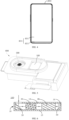
- the electronic device may include a housing 200, a display assembly 400, and a camera assembly 600.
- the display assembly 400 and the camera assembly 600 may be both arranged on the housing 200.
- the electronic device may be an electronic apparatus or a mobile terminal, or other electronic devices with display and camera functions.
- the electronic device may be a mobile phone, a tablet computer, a notebook computer, a smart bracelet, a smart watch, a smart helmet, smart glasses, or the like.
- a mobile phone may be taken as an example for description. It can be understood that, the electronic device may also in other specific forms, which may not be limited here.
- the case 200 may be an outer shell of the mobile phone, which may protect internal components inside the mobile phone (for example, a main board, a battery, or the like).
- the housing 200 may specifically include a front shell 202 and a rear shell 204 connected to the front shell 202.
- the front shell 202 may be connected to the rear shell 204, and a receiving cavity 206 may be defined by the front shell 202 and the rear shell 204.
- the receiving cavity 206 may be configured to receive the internal components of the mobile phone.
- the rear shell 204 may be in shape of a rectangle, a rounded rectangle, or the like.
- the rear shell 204 may be made of plastic, glass, ceramic, fiber composite material, metal (for example, stainless steel, aluminum, or the like), or other suitable materials, or a combination of these materials.
- a portion of the rear shell 204 may also be made of dielectric material or other low-conductivity materials.
- the rear shell 204 or at least some structures constituting the rear shell 204 may be made of metal elements.
- the display assembly 400 may be electrically connected to the camera assembly 600, a battery, a processor, or the like.
- the display assembly 400 may be configured to display information.
- the display assembly 400 may include a cover 402 and a display screen 404.
- the display screen 404 may be embedded in the front shell 202.
- the cover 402 may cover the display screen 404 to protect the display screen 404.
- the cover plate 402 may be made of a material with good light permeability, such as glass, plastic, or the like.
- the display screen 404 may include a display region 401 and a non-display region 403.
- the non-display region 403 may be arranged at one side of the display region 401 or may be arranged around a periphery of the display region 401.
- the first camera module 100 may be a periscope telephoto camera module, compared to a vertical lens module, the periscope lens module in the first camera module 100 may reduce a height requirement of the camera module by changing a transmission path of light. In this way, an overall thickness of the electronic device may also be reduced. More specifically, as shown in FIG. 6 , the first camera module 100 includes a fixing member 10, a rotating member 20, a lens assembly 30, a focusing assembly 40, an image sensor 50, and other elements. In some embodiments, the rotating member 20, the lens assembly 30, the focusing assembly 40, and the image sensor 50 are arranged on the fixing member 10. In some embodiments, the rotating member 20, the lens assembly 30, the focusing assembly 40, and the image sensor 50 are received in the fixing member 10.
- these components may also be disposed outside the fixing member 10.
- the rotating member 20 may be arranged on the fixed member 10. After light enters or is incident into the first camera module 100, the light may be redirected by the rotating member 20, and then transmitted through the lens assembly 30 and the focusing assembly 40, and finally transmitted into the image sensor 50.
- the image sensor 50 may further sense the light.
- the focusing assembly 40 is arranged between the lens assembly 30 and the image sensor 50, and the transmission distance of the light between the lens assembly 30 and the image sensor 50 may be shortened, and thus the arrangement of components on the fixing member 10 may be more compact.
- the fixing member 10 may be configured to connect, carry, and fix the components of the first camera module 100, such as the rotating member 20, the lens assembly 30, the focusing assembly 40, and the image sensor 50.
- the first camera module 100 may be arranged in the mobile phone as an entirety, and then the first camera module 100 may be fixedly connected to other components in the mobile phone.
- the fixing member 10 may be a mounting bracket, and other components of the first camera module 100 may be directly or indirectly mounted on the mounting bracket.
- the fixing member 10 may also be a casing, such as a case having a receiving space, and other components of the first camera module 100 may be received in the casing.
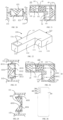
- the fixing member 10 includes a top wall 13, a plurality of sidewalls 14 connected to the top wall 13, and a bottom wall 15 opposite to the top wall 13.
- the top wall 13, the plurality of side walls 14, and the bottom wall 15 cooperatively define or enclose a receiving space configured to receive the rotating member 20, the lens assembly 30, the focusing assembly 40, the image sensor 50, and other suitable components.
- the top wall 13 defines a light incident hole 13a running through the top wall 13, and external light may enter the first camera module 100 through or via the light incident hole 13a.
- the plurality of side walls 14 of the fixing member 10 includes a first side wall 140, a second side wall 141 substantially perpendicularly connected to the first side wall 140, a third side wall 142 substantially parallel to the second side wall 141 and substantially perpendicularly connected to the first side wall 140, and a fourth side wall 143 substantially perpendicularly connected to the second side wall 141 and the third side wall 142 and further substantially parallel to the first side wall 140.
- a portion of the third side wall 142 at a position adjacent to or close to the fourth side wall 143 protrudes outwardly in a direction away from the second side wall 141, and thus a bent portion may be formed.
- the bent portion may include a pair of fifth side walls 144 and a sixth side wall 145 formed by extending or protruding from the third side wall 143.
- the pair of fifth side walls 144 may be arranged oppositely to each other, and the sixth side wall 145 may be connected to the pair of fifth side walls 144.
- Components that receive the light which has been redirected is arranged on the fourth side wall 143.
- At least one of the top wall 13 and the bottom wall 15 may be omitted, and as long as the second side wall 141, the third side wall 142, and the fifth side walls 144 and the sixth side wall 145 protruding from the third side wall 142 are arranged, as shown in FIG. 9 .
- the rotating member 20 includes a base 22 and a first light-redirecting member 24.
- the base 22 may be disposed in the fixing member 10.
- the first light-redirecting member 24 may be fixedly mounted on the base 22, and may be disposed correspondingly to the light incident hole 13a of the fixing member 10.
- the first light-redirecting member 24 may be configured to receive the light entering through the light incident hole 13a to redirect the light. More specifically, the first light-redirecting member 24 may be fixed to an inclined surface of the base 22 by means of adhesive or the like.
- the first light-redirecting member 24 may be implemented as components that is capable of changing a transmission direction of the light by reflection, such as a plane mirror (also referred to as a reflecting mirror), a prism (such as a reflecting prism), or the like.
- the first light-redirecting member 24 may be fixed to the base 22 via the matching or cooperation between the reflecting surface 242 and the inclined surface of the base 22 for fixing the first light-redirecting member 24.
- the incident surface 240 may be substantially perpendicular to the exiting surface 244. The light may be incident into the incident surface 240 after transmitting through the light incident hole 13a, reflected by the reflecting surface 242 to change the transmission direction of the light, and then further exited or emitted out from the exiting surface 244.
- the first light-redirecting member 24 formed by the incident surface 240 and the backlight surface 246 arranged according to the distance range may be moderate in volume, which may be better fit into the first camera module 100 to form a more compact and miniaturized first camera module, camera assembly 600, and electronic device. Thus, it is possible to meet more consumer needs.
- the quadrangular prism may be formed by cutting off a part of a corner formed by the reflecting surface 242 and the exiting surface 244 of the foregoing triangular prism. It should be pointed out that, as shown in FIGS. 13, 15 , and 16 , in practical applications, due to the incident light, the reflecting surface 242 may often be inclined with respect to a horizontal direction, and the light-redirecting member 24 has an asymmetric structure in a reflecting direction of the light when the light is reflected by the reflecting surface 242, and the reflecting surface 242 may have an actual optical area at the side away from the light incident hole 13a smaller or less than the side close to or adjacent to the light incident hole 13a.
- the part of the reflecting surface 242 away from the light incident hole 13a may reflect less light or may be even unable to reflect light. In other words, this part of the reflecting surface 242 has less contribution to the reflection of light, or even has no contribution to the reflection of light.
- the corner of the triangular prism away from the light incident hole 13a is cut off.
- the reflecting surface 242 may also be inclined at other degrees with respect to the incident surface 240, such as 30 degrees, 60 degrees, or the like; the incident surface 240 may not be perpendicular to the exiting surface 244, for example, the incident surface 240 may be inclined or tilt with respect to the exiting surface 244 at an angle of 80 degrees, 90 degrees, or the like; the backlight surface 246 may not be parallel to the incident surface 240, or the like; as long as the light redirected by the first light-redirecting member 24 may be received by the lens assembly 30.
- the first light-redirecting member 24 may also be other reflecting prisms, such as a double-reflection prism, a triple-reflection prism, a fourth-reflection prism, or the like
- the aforesaid reflecting prism may be made of a material with relatively good light permeability, such as glass, plastic, or the like.
- a hardening treatment may be performed on the reflecting prism to form a hardened layer on the incident surface 240, the reflecting surface 242, the exiting surface 244, the backlight surface 246, or the like.
- the hardening treatment may be infiltration of lithium ions, or a method such as attaching a film to each surface of the prism without affecting the redirection of light by the first light-redirecting member 24.
- the number of the first light-redirecting members 24 may be one. At this time, the light may be transmitted through the first light-redirecting member 24 and redirected by the first light-redirecting member 24 for once, and then transmitted through the lens assembly 30 and the focusing assembly 40, and finally transmitted to or reach the image sensor 50. Of course, the number of the first light-redirecting members 24 may also be two or more. At this time, the light may be transmitted through the plurality of first light-redirecting members 24 and redirected by the plurality of first light-redirecting members 24 for multiple times, after that the light may be transmitted through the lens assembly 30 and the focusing assembly 40, and finally transmitted to the image sensor 50. The number of the first light-redirecting members 24 may be set according to actual needs, and will not be specifically limited in some embodiments of the present disclosure.
- the lens assembly 30 may be fixed in the accommodating space formed by the fixing member 10 and disposed at one side of the first light-redirecting member 24 at which the exiting surface 244 is disposed, in order to receive and further transmit the light deflected or redirected by the first light-redirecting member 24. More specifically, the lens assembly 30 may include a clamping member/ holder / snapping member 32 and a lens unit 34. In some embodiments, the lens unit 34 may be fixed to the holder 32, for example, by means of glue bonding, welding, clamping, or the like. At this time, the clamping member 32 may be directly fixed to the fixing member 10.
- the reflecting surface may be disposed at one side of first reflecting prism 411 away from the lens assembly 30, and the reflecting surface may be disposed at an angle of approximately 45° from the optical axis A1 of the lens assembly 30.
- the exiting surface may be disposed at one side of the first reflecting prism 411 close to or adjacent to the third light-redirecting member 42, and the exiting surface may be substantially perpendicular to the incident surface. In this way, the light transmitting through the lens assembly 30 may enter an interior of the first reflecting prism 411 from the incident surface, may be redirected by the reflecting surface, and may be further transmitted out of the first reflecting prism 411 from the exiting surface and further transmitted to the third light-redirecting member 42.
- the third light-redirecting member 42 shown in FIG. 9 may be replaced by the third light-redirecting member 42 shown in FIG. 19 .
- the third light-redirecting member 42 may utilize a pair of reflecting prisms to replace the pair of reflecting mirrors.
- the reflecting mirror and the reflecting prism may also be used in combination.
- the second light-redirecting member 41 may include a reflecting mirror and a reflecting prism, that is to say, only one reflecting prism may be used to replace a reflecting mirror.
- the bent portion may be arranged at an end of the second side wall 141. Different from the bent portion dividing the third side wall 142 into two portions as shown in FIG. 19 , in the bent portion shown in FIGS. 21-25 , the bent portion may include the fifth side wall 144 and the sixth side wall 145 protruding from the third side wall 142.
- the fifth side wall 144 may be disposed opposite to the fourth side wall 143.
- the sixth side wall 145 may be connected to the fifth side wall 144 and an end portion of the fourth side wall 143 extending toward the sixth side wall 145.
- the fifth side wall 144 may be provided with a component that receives light that has been redirected, such as the image sensor 50 shown in FIG. 21 .
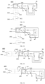
- the focusing assembly 40 may be arranged opposite to and face the lens assembly 30 and the image sensor 50, and may be movable along the direction of the optical axis A1 of the lens assembly 30, in order to change the distances between the focusing assembly 40 and the lens assembly 30 and between the focusing assembly 40 and the image sensor 50 respectively, thereby achieving the focusing or zooming of the first camera module 100.
- the containing space may be defined by the fourth side wall 143, the fifth side wall 144, the sixth side wall 145, the bottom wall 151 of the bending portion, and the top wall 131 of the bending portion.
- the containing space may communicate with the accommodating space.
- the focusing assembly 40 may include a fourth light-redirecting member 4001, a second moving member 4004, and a second driving mechanism 4005.
- the fourth light-redirecting member 4001 may be fixed on the second moving member 4004.
- a portion of the second driving mechanism 4005 may be placed or received in the containing space and another portion of the second driving mechanism 4005 may be placed or received in the space of the accommodating space facing the containing space.
- the second driving mechanism 4005 may be connected between the sixth side wall 145 and the second moving member 4004, and connected between the second side wall 141 and the second moving member 4004.
- the fourth light-redirecting member 4001 in this case may be similar the fourth light-redirecting member 4001 shown in FIG. 21 , and the difference between the fourth light-redirecting member 4001 in this case and the fourth light-redirecting member 4001 shown in FIG. 21 lies in that, in the fourth light-redirecting member 4001 in this case, two reflecting mirrors may be used to replace one reflecting prism.
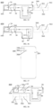
- the fourth light-redirecting member 4001 may include a fourth reflecting mirror 4002, a fifth reflecting mirror 4003, a second moving member 4004, and a second driving mechanism 4005.
- the fourth reflecting mirror 4002 may have a reflecting surface
- the fifth reflecting mirror 4003 may have a reflecting surface.
- the reflecting surface of the fourth reflecting mirror 4002 may be arranged at one side close to the fifth reflecting mirror 4003.
- the reflecting surface of the fifth reflecting mirror 4003 may be arranged at one side close to the fourth reflecting mirror.
- the reflecting surface of the fourth reflecting mirror 4002 may be substantially perpendicular to the reflecting surface of the fifth reflecting mirror 4003.
- the reflecting surface of the fourth reflecting mirror 4002 may be further disposed at one side adjacent to the lens assembly 30, and may be arranged at an angle of approximately 45° from the optical axis A1 of the lens assembly 30.
- the reflecting surface of the fifth reflecting mirror 4003 may be further disposed at one side close to the image sensor 50, and may be arranged at an angle of approximately 45° from the optical axis A1 of the lens assembly 30. In this way, the light transmitting through the lens assembly 30 may be redirected to the fourth reflecting mirror 4002, redirected by the reflecting surface of the fourth reflecting mirror 4002 to the reflecting surface of the fifth reflecting mirror 4003, and may be further redirected to the image sensor 50 via the reflecting surface of the fifth reflecting mirror 4003.
- some embodiments of the present disclosure may not be limited to the aforesaid terms “light-redirecting member”, “first light-redirecting member”, “second light-redirecting member”, “third light-redirecting member”, and “fourth light-redirecting member”, and the above terms having similar structures may be interchanged according to actual conditions. Furthermore, some embodiments of the present disclosure may not be limited to the aforesaid terms such as “reflecting prism”, “prism”, “first reflecting prism”, “second reflecting prism”, and “third reflecting prism”, and the above terms having similar structures may be interchanged according to actual conditions.
- Some embodiments of the present disclosure may not be limited to the aforesaid terms such as “reflecting mirror”, “plane mirror”, “first reflecting mirror”, “second reflecting mirror”, “third reflecting mirror”, “fourth reflecting mirror”, and “fifth reflecting mirrors”, and the above terms having similar structures may be interchanged according to actual conditions.
- first driving mechanism 36, the second driving mechanism 424, and the second driving mechanism 4005 may all be electromagnetic driving mechanisms.
- the first driving mechanism 36, the second driving mechanism 424, and the second driving mechanism 4005 may not be limited to the above electromagnetic driving mechanisms.
- the first driving mechanism 36, the second driving mechanism 424, and the second driving mechanism 4005 may also be a piezoelectric driving mechanism or a memory alloy driving mechanism. In the actual production and assembly process, different driving mechanisms may be used according to requirements.
- the image sensor 50 is arranged in the accommodating space, and specifically arranged at one side of the lens assembly 30 away from the rotating member 20, to receive and sense the light transmitting through the focusing assembly 40.
- the image sensor 50 may be disposed in the containing space and more specifically, the image sensor 50 may be disposed on the fifth side wall 144 away from the fourth side wall 143, to receive and sense the light transmitted through the focusing assembly 40.
- the image sensor 50 may adopt a complementary metal oxide semiconductor (CMOS) photosensitive element or a charge-coupled device (CCD) photosensitive element.
- CMOS complementary metal oxide semiconductor
- CCD charge-coupled device
- the components configured to receive the light transmitting through the focusing assembly 40 may also be an image receiver including the image sensor 50. It may be understood that, the image receiver may not be limited to the image sensor 50, may also be other.
- the rotation of the fixing member 10 on the two rotating shafts of the rotating member 20 may be detected, or the movement of the fixing member 10 in the direction of the optical axis A1 of the lens assembly 30 may be detected, in order to drive the base 22 to further drive the first light-redirecting member 24 to make a corresponding compensation movement, in order to compensate for the deviation of the incident light entering from the light incident hole 13a due to the jitter of the fixing member 10, thereby avoiding or reducing adversely effects on the imaging quality of the camera due to the deviation of the incident light.
- the focusing assembly 40 may be controlled to move to adjust the focus of the lens assembly 30.
- the lens assembly 30 and the focusing assembly 40 may be controlled to move separately or individually by detecting the imaging effect on the image sensor 50, in order to adjust the focus of the lens assembly 30
- the wide-angle main camera that is, the third camera module 500
- the third camera module 500 may have an angle of view being a normal angle of view, and the angle of view of the third camera module 500 may be in range of 80-110 degrees.
- the third camera module 500 may have high pixels and large pixels.
- the third camera module 500 may be configured for non-distant view or non-near view. Instead, the third camera module 500 may shoot the object normally.
- image effects such as background blurring and partial sharpening of pictures may be acquired.
- the angle of view of the first camera module 100 may be approximately 10 degrees, approximately 12 degrees, approximately 15 degrees, approximately 20 degrees, approximately 26 degrees, approximately 30 degrees, or the like.
- the angle of view of the second camera module 300 may be approximately 110 degrees, approximately 112 degrees, approximately 118 degrees, approximately 120 degrees, approximately 125 degrees, approximately 130 degrees, or the like.
- the angle of view of the third camera module 500 may be approximately 80 degrees, approximately 85 degrees, approximately 90 degrees, approximately 100 degrees, approximately 105 degrees, approximately 110 degrees, or the like.
- FIGS. 27 to 30 are respectively structural schematic views of the camera assembly 600 according to some embodiments of the present disclosure.
- the first light-redirecting member 24 may have a first center point 248, the second camera module 300 may have a second center point 302, and the third camera module 500 may have a third center point 502.
- the first center point 248, the second center point 302, and the third center point 502 may be located in a straight line and substantially perpendicular to the optical axis A1 of the lens assembly 30.
- the first center point 248, the second center point 302, and the third center point 502 being located in a straight line means that an orthographic projection of the first center point 248 on the rear shell 204, an orthographic projection of the second center point 302 on the rear shell 204, and an orthographic projection of the third center point 502 on the rear shell 204 may be located in a straight line. That is, when the light enters the mobile phone from the front to the rear shell 204 and is substantially perpendicular to the rear shell 204, the projections of the first center point 248, the second center point 302, and the third center point 502 projected on the rear shell 204 may be located in a straight line.
- a length of the first camera module 100 along the direction of the optical axis A1 of the lens assembly 30 may be greater than a length of the second camera module 300 along the direction of the optical axis A1 of the lens assembly 30 and greater than a length of the third camera module 500 along the direction of the optical axis A1 of the lens assembly 30.
- the first camera module 100 is a periscope telephoto camera, includes the first light-redirecting member 24, the lens assembly 30, the focusing assembly 40, and the image sensor 50, an optical path formed by the first light-redirecting member 24, the lens assembly 30, the focusing assembly 40, and the image sensor 50 may not be in a straight line, and a certain distance needs to be set during the light redirection and transmission, while an optical path formed by the second camera module 300 or the third camera module 500 in the shooting process may be in straight line. In this way, the length of the first camera module 100 may be greater than the length of the second camera module 300 or the length of the third camera module 500.
- FIG. 37 is a rear view of the electronic device according to other embodiments of the present disclosure.
- the camera assembly 600 may include the aforementioned first camera module 100, the second camera module 300, and the third camera module 500.
- FIGS. 38 to 39 show the arrangement of the three camera modules.
- the center points of the first camera module 100, the second camera module 300, and the third camera module 500, that is, the first, second, and third center points 248, 302, 502 may disposed in or enclose a triangle.
- the first, second, and third center points 248, 302, 502 may be surrounded to from a straight triangle. More specifically, the second and third center points 302, 502 may be located in a straight line and may be substantially parallel to the optical axis A1 of the lens assembly 30.
- FIG. 40 is a schematic structural view of the housing 200 of the present disclosure
- FIG. 41 is a schematic structural view in still another embodiment of the electronic device according to other embodiments of the present disclosure.
- the following may describe the positional relationship and connection relationship among the three camera modules and the housing 200.
- the housing 200 may define three openings, and lines connecting the center points of the three openings may be located in a straight line. More specifically, the three openings may be opened or defined on the rear shell 204 of the housing 200, and include a first opening 204a, a second opening 204b, and a third opening 204c.
- the housing 200 may define the receiving cavity 206, that is, the front shell 202 and the rear shell 204 of the housing 200 may be surrounded or enclosed to define the receiving cavity 206.
- the receiving cavity 206 may communicate to the first opening 204a, the second opening 204b, and the third opening 204c.
- the first camera module 100, the second camera module 300, and the third camera module 500 may be mounted or received in the receiving cavity 206, and the three camera modules may receive incident light through the first opening 204a, the second opening 204b, and the third opening 204c, respectively.
- the first edge 201 may be arranged substantially perpendicularly to the second edge 203, and the first edge 201 may be connected to the second edge 203 via an arc fillet, as shown in FIGS. 41-43 . In this way, edges at the back of the mobile phone may be rounded, and the touch of the mobile phone may be better.
- the lines connecting the center points of the first opening 204a, the second opening 204b, and the third opening 204c may be substantially parallel to the pair of first edges 201. That is, the three camera modules may be arranged in an L shape.
- the lines connecting the center points of the first opening 204a, the second opening 204b, and the third opening 204c may be substantially parallel to the pair of second edges 203. That is, the three camera modules may be arranged in a straight line.
- the lines connecting the center points of the first opening 204a, the second opening 204b, and the third opening 204c may substantially coincide with the first center line 2044 of the rear shell 204, that is, the camera assembly 600 may be located in the middle of the upper half of the phone. It may be understood that, the camera assembly 600 may be located in the middle of the upper half of the mobile phone, which facilitates the stacking of the components of the mobile phone and makes the entire appearance of the mobile phone more beautiful.
- the orthographic projection of the first camera module 100 projected in the thickness direction of the mobile terminal, the orthographic projection of the second camera module 300 projected in the thickness direction of the mobile terminal, or the orthographic projection of the third camera module 500 may be partly located in the display region 401, and partly located in the non-display region 403, which will not be specifically limited in some embodiments of the present disclosure.
Landscapes
- Physics & Mathematics (AREA)
- General Physics & Mathematics (AREA)
- Optics & Photonics (AREA)
- Engineering & Computer Science (AREA)
- Signal Processing (AREA)
- Multimedia (AREA)
- Human Computer Interaction (AREA)
- Studio Devices (AREA)
Claims (15)
- Kameramodul (100) für ein mobiles Endgerät, umfassend:ein erstes Lichtumlenkungselement (24), das dazu konfiguriert ist, in das Kameramodul (100) einfallendes Licht umzulenken;eine Linsenanordnung (30), die dazu konfiguriert ist, das durch das erste Lichtumlenkungselement (24) umgelenkte Licht zu übertragen;einen Bildempfänger (50), wobei die Linsenanordnung (30) zwischen dem ersten Lichtumlenkungselement (24) und dem Bildempfänger (50) angeordnet ist, und das Licht von dem ersten Lichtumlenkungselement (24) zu der Linsenanordnung (30) übertragen und weiter zu dem Bildempfänger (50) übertragen wird;eine Fokussierungsanordnung (40), die dazu konfiguriert ist, das sich durch die Linsenanordnung (30) übertragende Licht zu empfangen und zu dem Bildempfänger (50) zu übertragen;wobei die Fokussierungsanordnung (40) ein zweites Lichtumlenkungselement (41) und ein drittes Lichtumlenkungselement (42) umfasst, die dazu konfiguriert sind, einen Übertragungsabstand des Lichts von der Linsenanordnung (30) zu dem Bildempfänger (50) durch Umlenken des Lichts zu ändern, wobei eine relative Verschiebung zwischen dem zweiten Lichtumlenkungselement (41) und dem dritten Lichtumlenkungselement (42) anpassbar ist;wobei eine Richtung, in der das Licht in die Fokussierungsanordnung (40) einfällt, parallel zu einer Richtung ist, in der das Licht aus der Fokussierungsanordnung (40) ausgegeben wird;wobei das Kameramodul (100) ferner ein Befestigungselement (10) umfasst, und das Befestigungselement (10) Folgendes umfasst:eine obere Wand (13), die ein Lichteinfallsloch (13a) definiert;eine untere Wand (15) parallel zu und gegenüber der oberen Wand (13);eine erste Seitenwand (140), die mit der oberen Wand (13) und der unteren Wand (15) verbunden ist;eine zweite Seitenwand (141), die mit der ersten Seitenwand (140), der oberen Wand (13) und der unteren Wand (15) verbunden ist;eine dritte Seitenwand (142), die mit der ersten Seitenwand (140), der oberen Wand (13) und der unteren Wand (15) verbunden ist; undeine vierte Seitenwand (143), die mit der zweiten Seitenwand (141), der dritten Seitenwand (142), der oberen Wand (13) und der unteren Wand (15) verbunden ist;wobei der Bildempfänger (50) auf der vierten Seitenwand (143) angeordnet ist;wobei die untere Wand (15) bzw. die obere Wand (13) mit gegenüberliegenden Seiten der ersten Seitenwand (140) verbunden sind;dadurch gekennzeichnet, dass die erste Seitenwand (140), die zweite Seitenwand (141), die dritte Seitenwand (142) und die vierte Seitenwand (143) zusammenwirkend einen ersten Aufnahmeraum definieren, der dazu konfiguriert ist, das erste Lichtumlenkungselement (24), die Linsenanordnung (30) und das zweite Lichtumlenkungselement (41) aufzunehmen,wobei ein Abschnitt der dritten Seitenwand (142) an einer Position angrenzend an die vierte Seitenwand (143) in einer Richtung weg von der zweiten Seitenwand (141) nach außen hervorsteht, so dass er einen gebogenen Abschnitt bildet; undwobei der gebogene Abschnitt, die untere Wand (15) und die obere Wand (13) zusammenwirkend einen zweiten Aufnahmeraum definieren, wobei der erste Aufnahmeraum mit dem zweiten Aufnahmeraum in Verbindung steht, wobei das zweite Lichtumlenkungselement (41) in dem ersten Aufnahmeraum an einer Position gegenüber dem zweiten Aufnahmeraum aufgenommen ist, und das dritte Lichtumlenkungselement (42) in dem zweiten Aufnahmeraum aufgenommen ist.
- Kameramodul (100) nach Anspruch 1, wobei das zweite Lichtumlenkungselement (41) einen Reflexionsspiegel umfasst, und der Reflexionsspiegel eine erste Reflexionsfläche (4101) und eine zweite Reflexionsfläche (4102), die mit der ersten Reflexionsfläche (4101) verbunden ist, aufweist.
- Kameramodul (100) nach Anspruch 2, wobei das dritte Lichtumlenkungselement (42) ein Reflexionsprisma (425) umfasst, und das Reflexionsprisma (425) Folgendes umfasst:eine Einfallsfläche (4201), wobei das Licht von der Einfallsfläche (4201) in das Reflexionsprisma eintritt;eine Mehrzahl von Reflexionsflächen (4202, 4203), die dazu konfiguriert sind, das in das Reflexionsprisma (425) eintretende Licht zu reflektieren; undeine Austrittsfläche, wobei das durch die Mehrzahl von Reflexionsflächen (4202, 4203) reflektierte Licht von der Austrittsfläche aus dem Reflexionsprisma (425) ausgegeben wird.
- Kameramodul (100) nach Anspruch 3, wobei das Kameramodul (100) ferner ein Bewegungselement (423) umfasst, wobei eines des Reflexionsspiegels und des Reflexionsprismas (425) auf dem Bewegungselement (423) angeordnet ist, und das Bewegungselement (423) dazu konfiguriert ist, die relative Verschiebung zwischen dem zweiten Lichtumlenkungselement (41) und dem dritten Lichtumlenkungselement (42) zu ändern.
- Kameramodul (100) nach einem der Ansprüche 1-4, wobei das Kameramodul (100) ferner eine Basis (22) umfasst, die relativ zu dem Befestigungselement (10) drehbar ist;
wobei die Linsenanordnung (30), der Bildempfänger (50) und die Fokussierungsanordnung (40) alle auf dem Befestigungselement (10) angeordnet sind, und das erste Lichtumlenkungselement (24) fest auf der Basis (22) montiert ist. - Kameramodul (100) nach Anspruch 5, wobei das Befestigungselement (10) Folgendes umfasst:eine erste Hülle, die durch die erste Seitenwand (140), die zweite Seitenwand (141), die dritte Seitenwand (142) und die vierte Seitenwand (143) gebildet ist und den ersten Aufnahmeraum definiert, der dazu konfiguriert ist, das erste Lichtumlenkungselement (24), die Linsenanordnung (30) und das zweite Lichtumlenkungselement (41) aufzunehmen; undeine zweite Hülle, die sich von einer Seite der ersten Hülle erstreckt und den zweiten Aufnahmeraum definiert;wobeider gebogene Abschnitt Folgendes umfasst:ein Paar fünfter Seitenwände (144), die sich von der dritten Seitenwand (142) erstrecken;eine sechste Seitenwand (145), die mit dem Paar fünfter Seitenwände (144) verbunden ist,eine obere Wand (131) des gebogenen Abschnitts, die von der oberen Wand (13) hervorsteht, undeine untere Wand (151) des gebogenen Abschnitts, die von der unteren Wand (15) hervorsteht; undwobei das Paar fünfter Seitenwände (144), die sechste Seitenwand (145), die untere Wand (151) des gebogenen Abschnitts und die obere Wand (131) des gebogenen Abschnitts zusammenwirkend die zweiten Hülle bilden.
- Kameramodul (100) nach einem der Ansprüche 1-6, wobei die Linsenanordnung (30) zwischen dem ersten Lichtumlenkungselement (24) und dem zweiten Lichtumlenkungselement (41) angeordnet ist;
wobei das erste Lichtumlenkungselement (24) anpassbar ist und ein Winkel zwischen dem ersten Lichtumlenkungselement (24) und der Linsenanordnung (30) anpassbar ist. - Kameramodul (100) nach einem der Ansprüche 1-7, wobei das erste Lichtumlenkungselement (24) ein erstes Reflexionsprisma oder einen ersten Reflexionsspiegel umfasst;wobei das erste Reflexionsprisma Folgendes umfasst:eine erste Einfallsfläche (240), wobei das Licht von der ersten Einfallsfläche (240) in das erste Reflexionsprisma eintritt;eine erste Reflexionsfläche (242), die dazu konfiguriert ist, das in das erste Reflexionsprisma eintretende Licht zu reflektieren; undeine erste Austrittsfläche (244), wobei das durch die erste Reflexionsfläche (242) reflektierte Licht von der ersten Austrittsfläche (244) aus dem ersten Reflexionsprisma ausgegeben wird und weiter zu der Linsenanordnung (30) übertragen wird; oderwobei der erste Reflexionsspiegel eine Reflexionsfläche aufweist, die dazu konfiguriert ist, das in den ersten Reflexionsspiegel eintretende Licht zu reflektieren und zu der Linsenanordnung (30) zu übertragen.
- Kameramodul (100) nach Anspruch 1, wobei das dritte Lichtumlenkungselement (42) Folgendes umfasst:ein erstes Bewegungselement (423), das dazu konfiguriert ist, das dritte Lichtumlenkungselement (42) anzutreiben, so dass es sich relativ zu dem zweiten Lichtumlenkungselement (41) bewegt;einen zweiten Reflexionsspiegel (421) oder ein zweites Reflexionsprisma, wobei der zweite Reflexionsspiegel oder das zweite Reflexionsprisma an dem ersten Bewegungselement (423) befestigt ist, eine Reflexionsfläche aufweist und dazu konfiguriert ist, das durch das zweite Lichtumlenkungselement (41) umgelenkte Licht zu reflektieren; undeinen dritten Reflexionsspiegel (422) oder ein drittes Reflexionsprisma, wobei der dritte Reflexionsspiegel oder das dritte Reflexionsprisma an dem ersten Bewegungselement (423) befestigt ist, eine Reflexionsfläche aufweist und dazu konfiguriert ist, das durch den zweiten Reflexionsspiegel oder das zweite Reflexionsprisma reflektierte Licht zu empfangen, und ferner das Licht aus dem dritten Lichtumlenkungselement (42) zu reflektieren und zu übertragen;wobei der Bildempfänger (50) dazu konfiguriert ist, das durch das zweite Lichtumlenkungselement (41) umgelenkte Licht zu empfangen.
- Kameramodul (100) nach Anspruch 1, wobei das dritte Lichtumlenkungselement (42) Folgendes umfasst:ein erstes Bewegungselement (423), das dazu konfiguriert ist, das dritte Lichtumlenkungselement (42) anzutreiben, so dass es sich relativ zu dem zweiten Lichtumlenkungselement (41) bewegt; undein viertes Reflexionsprisma (425), das an dem ersten Bewegungselement befestigt ist und Folgendes umfasst:eine zweite Einfallsfläche (4201), wobei das durch das zweite Lichtumlenkungselement (41) umgelenkte Licht von der zweiten Einfallsfläche (4201) in das vierte Reflexionsprisma eintritt;eine Mehrzahl von zweiten Reflexionsflächen (4202, 4203), die dazu konfiguriert sind, das in das vierte Reflexionsprisma eintretende Licht zu reflektieren; undeine zweite Austrittsfläche, wobei das durch die Mehrzahl von zweiten Reflexionsflächen reflektierte Licht von der zweiten Austrittsfläche aus dem dritten Lichtumlenkungselement (42) ausgegeben wird;wobei der Bildempfänger (50) dazu konfiguriert ist, das durch das zweite Lichtumlenkungselement (41) umgelenkte Licht zu empfangen.
- Kameramodul (100) nach Anspruch 8, wobei eine Lichtempfangsfläche des Bildempfängers (50) hin zu der ersten Austrittsfläche (244) des ersten Lichtumlenkungselements (24) und hin zu der zweiten Reflexionsfläche des zweiten Lichtumlenkungselements (41) weist, und der Bildempfänger (50) ein lichtempfindliches Komplementär-Metalloxid-Halbleiter(CMOS)-Element ist.
- Kameraanordnung (600) für ein mobiles Endgerät, die eine optische Achse (A1) aufweist und Folgendes umfasst:ein erstes Kameramodul (100), das das Kameramodul (100) nach einem der Ansprüche 1-11 ist, wobei das erste Lichtumlenkungselement (24) einen ersten Mittelpunkt (248) aufweist;ein zweites Kameramodul (300), das einen zweiten Mittelpunkt (302) aufweist; undein drittes Kameramodul (500), das einen dritten Mittelpunkt (502) aufweist;wobei das erste Kameramodul (100), das zweite Kameramodul (300) und das dritte Kameramodul (500) nebeneinander angeordnet sind, und der erste Mittelpunkt (248), der zweite Mittelpunkt (302) und der dritte Mittelpunkt (502) in einer geraden Linie angeordnet sind und senkrecht oder parallel zu der optischen Achse (A1) stehen.
- Kameraanordnung (600) nach Anspruch 12, wobei ein Sichtwinkel des dritten Kameramoduls (500) größer als ein Sichtwinkel des ersten Kameramoduls (100) und kleiner als ein Sichtwinkel des zweiten Kameramoduls (300) ist.
- Kameraanordnung (600) nach einem der Ansprüche 12-13, wobei ein Sichtwinkel des ersten Kameramoduls (100) im Bereich von 10-30 Grad liegt, ein Sichtwinkel des zweiten Kameramoduls (300) im Bereich von 110-130 Grad liegt und ein Sichtwinkel des dritten Kameramoduls (500) im Bereich von 80-110 Grad liegt.
- Mobiles Endgerät, umfassend:ein Gehäuse (200), wobei das Gehäuse (200) eine erste Öffnung (204a), eine zweite Öffnung (204b) und eine dritte Öffnung (204c) definiert, und Linien, die einen Mittelpunkt der ersten Öffnung (204a), einen Mittelpunkt der zweiten Öffnung (204b) und einen Mittelpunkt der dritten Öffnung (204c) verbinden, in einer geraden Linie angeordnet sind oder zusammenwirkend ein Dreieck bilden; unddie Kameraanordnung (600) nach einem der Ansprüche 12-14, wobei die Kameraanordnung (600) auf dem Gehäuse (200) angeordnet ist, das erste Kameramodul (100) entsprechend zu der ersten Öffnung (204a) angeordnet ist, das zweite Kameramodul (300) entsprechend zu der zweiten Öffnung (204b) angeordnet ist, und das dritte Kameramodul (500) entsprechend zu der dritten Öffnung (204c) angeordnet ist.
Applications Claiming Priority (2)
| Application Number | Priority Date | Filing Date | Title |
|---|---|---|---|
| CN201911361010.7A CN110879454A (zh) | 2019-12-25 | 2019-12-25 | 摄像头模组、潜望式摄像头模组、摄像头组件及电子装置 |
| CN201922379829.8U CN211149032U (zh) | 2019-12-25 | 2019-12-25 | 摄像头模组 |
Publications (2)
| Publication Number | Publication Date |
|---|---|
| EP3842848A1 EP3842848A1 (de) | 2021-06-30 |
| EP3842848B1 true EP3842848B1 (de) | 2025-01-22 |
Family
ID=73856963
Family Applications (1)
| Application Number | Title | Priority Date | Filing Date |
|---|---|---|---|
| EP20216786.2A Active EP3842848B1 (de) | 2019-12-25 | 2020-12-23 | Kameramodul, kameraanordnung und elektronische vorrichtung |
Country Status (3)
| Country | Link |
|---|---|
| US (2) | US11693221B2 (de) |
| EP (1) | EP3842848B1 (de) |
| WO (1) | WO2021129711A1 (de) |
Families Citing this family (6)
| Publication number | Priority date | Publication date | Assignee | Title |
|---|---|---|---|---|
| US12585092B2 (en) * | 2019-09-18 | 2026-03-24 | Ningbo Sunny Opotech Co., Ltd | Periscopic camera module and electronic device |
| US20220221574A1 (en) * | 2021-01-11 | 2022-07-14 | Movon Corporation | Camera and radar sensor system and error compensation method thereof |
| KR102597158B1 (ko) * | 2021-02-19 | 2023-11-02 | 삼성전기주식회사 | 촬상 광학계 |
| KR20220136141A (ko) * | 2021-03-31 | 2022-10-07 | 옵토튠 컨슈머 아게 | 광학 줌 시스템 |
| CN113140165B (zh) * | 2021-04-14 | 2022-07-12 | 武汉华星光电半导体显示技术有限公司 | 显示装置及其制作方法 |
| CN118655677B (zh) * | 2024-08-15 | 2025-01-28 | 宁波舜宇光电信息有限公司 | 一种镜头模组及电子设备 |
Citations (1)
| Publication number | Priority date | Publication date | Assignee | Title |
|---|---|---|---|---|
| US5780865A (en) * | 1995-08-11 | 1998-07-14 | Kabushiki Kaisha Toshiba | Apparatus for detecting images of particulates in liquid |
Family Cites Families (32)
| Publication number | Priority date | Publication date | Assignee | Title |
|---|---|---|---|---|
| JPH06194560A (ja) | 1992-12-25 | 1994-07-15 | Ricoh Co Ltd | 変倍撮影光学系 |
| US6498624B1 (en) | 1995-02-28 | 2002-12-24 | Canon Kabushiki Kaisha | Optical apparatus and image sensing apparatus mounted on the same surface of a board |
| WO2006018885A1 (ja) | 2004-08-19 | 2006-02-23 | Mitsubishi Denki Kabushiki Kaisha | 結像光学系およびこれを搭載したカメラ |
| CN1885081A (zh) | 2005-06-22 | 2006-12-27 | 郭鸿宾 | 利用调整物像距于光学放大系统的光学变倍方法 |
| CN100516962C (zh) * | 2005-09-23 | 2009-07-22 | 鸿富锦精密工业(深圳)有限公司 | 多段式对焦镜头模组 |
| JP4788953B2 (ja) | 2005-11-16 | 2011-10-05 | ソニー株式会社 | 撮像装置及びズームレンズ |
| US20080144171A1 (en) * | 2006-12-15 | 2008-06-19 | Nokia Corporation | Optical zoom system and devices having same |
| KR101476652B1 (ko) | 2008-07-11 | 2014-12-26 | 삼성전자주식회사 | 디지털 촬영장치, 제어방법 및 제어방법을 실행시키기 위한프로그램을 저장한 기록매체 |
| WO2010148363A2 (en) | 2009-06-18 | 2010-12-23 | Theia Technologies, Llc | Compact dome camera |
| US9383550B2 (en) | 2014-04-04 | 2016-07-05 | Qualcomm Incorporated | Auto-focus in low-profile folded optics multi-camera system |
| US9549107B2 (en) | 2014-06-20 | 2017-01-17 | Qualcomm Incorporated | Autofocus for folded optic array cameras |
| US9392188B2 (en) * | 2014-08-10 | 2016-07-12 | Corephotonics Ltd. | Zoom dual-aperture camera with folded lens |
| CN104635404A (zh) | 2015-01-22 | 2015-05-20 | 广东欧珀移动通信有限公司 | 光学变焦摄像模组及具有所述光学变焦摄像模组的移动终端 |
| KR102430566B1 (ko) | 2015-02-03 | 2022-08-09 | 삼성전자주식회사 | 촬상 장치, 이를 작동하는 작동 방법 및 이를 구비하는 무선 통신 단말기 |
| CN107820576A (zh) * | 2015-06-29 | 2018-03-20 | Lg伊诺特有限公司 | 双相机模块及光学装置 |
| CN106534655B (zh) * | 2017-01-11 | 2019-04-16 | Oppo广东移动通信有限公司 | 摄像头模组及移动终端 |
| KR102046472B1 (ko) | 2017-02-15 | 2019-11-19 | 삼성전기주식회사 | 손떨림 보정 반사모듈 및 이를 포함하는 카메라 모듈 |
| CN107317896B (zh) | 2017-06-29 | 2020-07-07 | 努比亚技术有限公司 | 一种双摄像头装置及移动终端 |
| WO2019002523A1 (en) | 2017-06-30 | 2019-01-03 | Polight As | MODULE WITH A PLURALITY OF CAMERAS TO INTEGRATE IN A MOBILE DEVICE |
| CN107493409B (zh) | 2017-07-18 | 2020-05-19 | 宇龙计算机通信科技(深圳)有限公司 | 一种光学变焦的摄像模组和移动终端 |
| EP4400892A3 (de) * | 2018-01-25 | 2024-10-16 | Tdk Taiwan Corp. | Optisches system |
| CN110398872A (zh) | 2018-04-25 | 2019-11-01 | 华为技术有限公司 | 一种镜头模组及照相机 |
| CN108600601B (zh) * | 2018-07-26 | 2020-01-17 | Oppo广东移动通信有限公司 | 摄像头模组、摄像头组件和电子装置 |
| US11616896B2 (en) * | 2019-01-08 | 2023-03-28 | Apple Inc. | Portable electronic device |
| WO2020224371A1 (zh) * | 2019-05-05 | 2020-11-12 | 华为技术有限公司 | 一种摄像模组、终端设备、成像方法及成像装置 |
| CN110913096A (zh) | 2019-05-05 | 2020-03-24 | 华为技术有限公司 | 一种摄像模组及电子设备 |
| KR102680342B1 (ko) * | 2019-09-23 | 2024-07-03 | 삼성전자주식회사 | 복수의 이미지 센서들에 의해 획득되는 이미지 데이터에 기초하여 비디오 hdr 처리를 수행하기 위한 전자 장치 |
| KR102801499B1 (ko) * | 2019-12-16 | 2025-05-02 | 삼성전자주식회사 | 카메라 조립체 및 이를 포함하는 전자 장치 |
| CN110879454A (zh) | 2019-12-25 | 2020-03-13 | Oppo广东移动通信有限公司 | 摄像头模组、潜望式摄像头模组、摄像头组件及电子装置 |
| CN211149032U (zh) | 2019-12-25 | 2020-07-31 | Oppo广东移动通信有限公司 | 摄像头模组 |
| CN213338283U (zh) | 2019-12-25 | 2021-06-01 | Oppo广东移动通信有限公司 | 潜望式摄像头模组、摄像头组件及手机 |
| CN111308643B (zh) | 2019-12-25 | 2024-04-12 | Oppo广东移动通信有限公司 | 摄像头模组、潜望式摄像头模组、摄像头组件及电子装置 |
-
2020
- 2020-12-15 US US17/122,525 patent/US11693221B2/en active Active
- 2020-12-23 EP EP20216786.2A patent/EP3842848B1/de active Active
- 2020-12-24 WO PCT/CN2020/138852 patent/WO2021129711A1/en not_active Ceased
-
2023
- 2023-06-28 US US18/342,871 patent/US12259532B2/en active Active
Patent Citations (1)
| Publication number | Priority date | Publication date | Assignee | Title |
|---|---|---|---|---|
| US5780865A (en) * | 1995-08-11 | 1998-07-14 | Kabushiki Kaisha Toshiba | Apparatus for detecting images of particulates in liquid |
Also Published As
| Publication number | Publication date |
|---|---|
| EP3842848A1 (de) | 2021-06-30 |
| US20230333353A1 (en) | 2023-10-19 |
| WO2021129711A1 (en) | 2021-07-01 |
| US12259532B2 (en) | 2025-03-25 |
| US11693221B2 (en) | 2023-07-04 |
| US20210199930A1 (en) | 2021-07-01 |
Similar Documents
| Publication | Publication Date | Title |
|---|---|---|
| EP3842848B1 (de) | Kameramodul, kameraanordnung und elektronische vorrichtung | |
| CN110879454A (zh) | 摄像头模组、潜望式摄像头模组、摄像头组件及电子装置 | |
| CN111308643B (zh) | 摄像头模组、潜望式摄像头模组、摄像头组件及电子装置 | |
| CN112887456B (zh) | 成像模组、摄像头组件及电子装置 | |
| CN108600594B (zh) | 成像模组、摄像头组件和电子装置 | |
| CN112532816B (zh) | 潜望式摄像模组及电子设备 | |
| EP3968074B1 (de) | Kameravorrichtung | |
| CN111835953B (zh) | 摄像模组及电子设备 | |
| EP3817357B1 (de) | Kameramodul, anordnung, elektronische vorrichtung, mobiles endgerät und fotografierverfahren | |
| CN214707821U (zh) | 潜望式摄像头模组、摄像头组件及电子装置 | |
| CN108965663A (zh) | 电子装置 | |
| CN108769493A (zh) | 摄像头组件和电子装置 | |
| CN211149032U (zh) | 摄像头模组 | |
| CN114666429B (zh) | 摄像头模组、潜望式摄像头模组及电子装置 | |
| CN209151242U (zh) | 成像模组、摄像头组件及电子装置 | |
| CN108777761B (zh) | 成像模组和电子装置 | |
| WO2022035216A1 (ko) | 반사모듈 및 이를 구비한 카메라 모듈 | |
| CN115623306A (zh) | 摄像模组及镜头组件 | |
| KR102876967B1 (ko) | 카메라 모듈 및 이동 단말기 | |
| CN115242904A (zh) | 电子设备 | |
| CN209105287U (zh) | 成像模组、摄像头组件及电子装置 | |
| CN212413257U (zh) | 摄像头模组、摄像头组件、电子装置 | |
| KR20250112047A (ko) | 카메라 모듈 | |
| KR20240043651A (ko) | 카메라 모듈 및 이를 포함하는 카메라 모듈 어셈블리 | |
| WO2024169340A1 (zh) | 电子设备 |
Legal Events
| Date | Code | Title | Description |
|---|---|---|---|
| PUAI | Public reference made under article 153(3) epc to a published international application that has entered the european phase |
Free format text: ORIGINAL CODE: 0009012 |
|
| STAA | Information on the status of an ep patent application or granted ep patent |
Free format text: STATUS: THE APPLICATION HAS BEEN PUBLISHED |
|
| AK | Designated contracting states |
Kind code of ref document: A1 Designated state(s): AL AT BE BG CH CY CZ DE DK EE ES FI FR GB GR HR HU IE IS IT LI LT LU LV MC MK MT NL NO PL PT RO RS SE SI SK SM TR |
|
| STAA | Information on the status of an ep patent application or granted ep patent |
Free format text: STATUS: REQUEST FOR EXAMINATION WAS MADE |
|
| 17P | Request for examination filed |
Effective date: 20211125 |
|
| RBV | Designated contracting states (corrected) |
Designated state(s): AL AT BE BG CH CY CZ DE DK EE ES FI FR GB GR HR HU IE IS IT LI LT LU LV MC MK MT NL NO PL PT RO RS SE SI SK SM TR |
|
| STAA | Information on the status of an ep patent application or granted ep patent |
Free format text: STATUS: EXAMINATION IS IN PROGRESS |
|
| 17Q | First examination report despatched |
Effective date: 20221124 |
|
| GRAP | Despatch of communication of intention to grant a patent |
Free format text: ORIGINAL CODE: EPIDOSNIGR1 |
|
| STAA | Information on the status of an ep patent application or granted ep patent |
Free format text: STATUS: GRANT OF PATENT IS INTENDED |
|
| INTG | Intention to grant announced |
Effective date: 20241004 |
|
| GRAS | Grant fee paid |
Free format text: ORIGINAL CODE: EPIDOSNIGR3 |
|
| GRAA | (expected) grant |
Free format text: ORIGINAL CODE: 0009210 |
|
| STAA | Information on the status of an ep patent application or granted ep patent |
Free format text: STATUS: THE PATENT HAS BEEN GRANTED |
|
| AK | Designated contracting states |
Kind code of ref document: B1 Designated state(s): AL AT BE BG CH CY CZ DE DK EE ES FI FR GB GR HR HU IE IS IT LI LT LU LV MC MK MT NL NO PL PT RO RS SE SI SK SM TR |
|
| REG | Reference to a national code |
Ref country code: GB Ref legal event code: FG4D |
|
| REG | Reference to a national code |
Ref country code: CH Ref legal event code: EP |
|
| REG | Reference to a national code |
Ref country code: IE Ref legal event code: FG4D |
|
| REG | Reference to a national code |
Ref country code: DE Ref legal event code: R096 Ref document number: 602020045096 Country of ref document: DE |
|
| REG | Reference to a national code |
Ref country code: NL Ref legal event code: FP |
|
| P01 | Opt-out of the competence of the unified patent court (upc) registered |
Free format text: CASE NUMBER: APP_9834/2025 Effective date: 20250226 |
|
| PG25 | Lapsed in a contracting state [announced via postgrant information from national office to epo] |
Ref country code: RS Free format text: LAPSE BECAUSE OF FAILURE TO SUBMIT A TRANSLATION OF THE DESCRIPTION OR TO PAY THE FEE WITHIN THE PRESCRIBED TIME-LIMIT Effective date: 20250422 |
|
| PG25 | Lapsed in a contracting state [announced via postgrant information from national office to epo] |
Ref country code: FI Free format text: LAPSE BECAUSE OF FAILURE TO SUBMIT A TRANSLATION OF THE DESCRIPTION OR TO PAY THE FEE WITHIN THE PRESCRIBED TIME-LIMIT Effective date: 20250122 |
|
| PG25 | Lapsed in a contracting state [announced via postgrant information from national office to epo] |
Ref country code: PL Free format text: LAPSE BECAUSE OF FAILURE TO SUBMIT A TRANSLATION OF THE DESCRIPTION OR TO PAY THE FEE WITHIN THE PRESCRIBED TIME-LIMIT Effective date: 20250122 |
|
| PG25 | Lapsed in a contracting state [announced via postgrant information from national office to epo] |
Ref country code: ES Free format text: LAPSE BECAUSE OF FAILURE TO SUBMIT A TRANSLATION OF THE DESCRIPTION OR TO PAY THE FEE WITHIN THE PRESCRIBED TIME-LIMIT Effective date: 20250122 |
|
| REG | Reference to a national code |
Ref country code: LT Ref legal event code: MG9D |
|
| PG25 | Lapsed in a contracting state [announced via postgrant information from national office to epo] |
Ref country code: NO Free format text: LAPSE BECAUSE OF FAILURE TO SUBMIT A TRANSLATION OF THE DESCRIPTION OR TO PAY THE FEE WITHIN THE PRESCRIBED TIME-LIMIT Effective date: 20250422 Ref country code: IS Free format text: LAPSE BECAUSE OF FAILURE TO SUBMIT A TRANSLATION OF THE DESCRIPTION OR TO PAY THE FEE WITHIN THE PRESCRIBED TIME-LIMIT Effective date: 20250522 |
|
| REG | Reference to a national code |
Ref country code: AT Ref legal event code: MK05 Ref document number: 1761887 Country of ref document: AT Kind code of ref document: T Effective date: 20250122 |
|
| PG25 | Lapsed in a contracting state [announced via postgrant information from national office to epo] |
Ref country code: HR Free format text: LAPSE BECAUSE OF FAILURE TO SUBMIT A TRANSLATION OF THE DESCRIPTION OR TO PAY THE FEE WITHIN THE PRESCRIBED TIME-LIMIT Effective date: 20250122 |
|
| PG25 | Lapsed in a contracting state [announced via postgrant information from national office to epo] |
Ref country code: LV Free format text: LAPSE BECAUSE OF FAILURE TO SUBMIT A TRANSLATION OF THE DESCRIPTION OR TO PAY THE FEE WITHIN THE PRESCRIBED TIME-LIMIT Effective date: 20250122 Ref country code: PT Free format text: LAPSE BECAUSE OF FAILURE TO SUBMIT A TRANSLATION OF THE DESCRIPTION OR TO PAY THE FEE WITHIN THE PRESCRIBED TIME-LIMIT Effective date: 20250522 |
|
| PG25 | Lapsed in a contracting state [announced via postgrant information from national office to epo] |
Ref country code: GR Free format text: LAPSE BECAUSE OF FAILURE TO SUBMIT A TRANSLATION OF THE DESCRIPTION OR TO PAY THE FEE WITHIN THE PRESCRIBED TIME-LIMIT Effective date: 20250423 Ref country code: BG Free format text: LAPSE BECAUSE OF FAILURE TO SUBMIT A TRANSLATION OF THE DESCRIPTION OR TO PAY THE FEE WITHIN THE PRESCRIBED TIME-LIMIT Effective date: 20250122 |
|
| PG25 | Lapsed in a contracting state [announced via postgrant information from national office to epo] |
Ref country code: AT Free format text: LAPSE BECAUSE OF FAILURE TO SUBMIT A TRANSLATION OF THE DESCRIPTION OR TO PAY THE FEE WITHIN THE PRESCRIBED TIME-LIMIT Effective date: 20250122 |
|
| PG25 | Lapsed in a contracting state [announced via postgrant information from national office to epo] |
Ref country code: SE Free format text: LAPSE BECAUSE OF FAILURE TO SUBMIT A TRANSLATION OF THE DESCRIPTION OR TO PAY THE FEE WITHIN THE PRESCRIBED TIME-LIMIT Effective date: 20250122 |
|
| PG25 | Lapsed in a contracting state [announced via postgrant information from national office to epo] |
Ref country code: SM Free format text: LAPSE BECAUSE OF FAILURE TO SUBMIT A TRANSLATION OF THE DESCRIPTION OR TO PAY THE FEE WITHIN THE PRESCRIBED TIME-LIMIT Effective date: 20250122 |
|
| PG25 | Lapsed in a contracting state [announced via postgrant information from national office to epo] |
Ref country code: DK Free format text: LAPSE BECAUSE OF FAILURE TO SUBMIT A TRANSLATION OF THE DESCRIPTION OR TO PAY THE FEE WITHIN THE PRESCRIBED TIME-LIMIT Effective date: 20250122 |
|
| PG25 | Lapsed in a contracting state [announced via postgrant information from national office to epo] |
Ref country code: IT Free format text: LAPSE BECAUSE OF FAILURE TO SUBMIT A TRANSLATION OF THE DESCRIPTION OR TO PAY THE FEE WITHIN THE PRESCRIBED TIME-LIMIT Effective date: 20250122 |
|
| PG25 | Lapsed in a contracting state [announced via postgrant information from national office to epo] |
Ref country code: EE Free format text: LAPSE BECAUSE OF FAILURE TO SUBMIT A TRANSLATION OF THE DESCRIPTION OR TO PAY THE FEE WITHIN THE PRESCRIBED TIME-LIMIT Effective date: 20250122 Ref country code: CZ Free format text: LAPSE BECAUSE OF FAILURE TO SUBMIT A TRANSLATION OF THE DESCRIPTION OR TO PAY THE FEE WITHIN THE PRESCRIBED TIME-LIMIT Effective date: 20250122 |
|
| REG | Reference to a national code |
Ref country code: DE Ref legal event code: R097 Ref document number: 602020045096 Country of ref document: DE |
|
| PG25 | Lapsed in a contracting state [announced via postgrant information from national office to epo] |
Ref country code: RO Free format text: LAPSE BECAUSE OF FAILURE TO SUBMIT A TRANSLATION OF THE DESCRIPTION OR TO PAY THE FEE WITHIN THE PRESCRIBED TIME-LIMIT Effective date: 20250122 |
|
| PG25 | Lapsed in a contracting state [announced via postgrant information from national office to epo] |
Ref country code: SK Free format text: LAPSE BECAUSE OF FAILURE TO SUBMIT A TRANSLATION OF THE DESCRIPTION OR TO PAY THE FEE WITHIN THE PRESCRIBED TIME-LIMIT Effective date: 20250122 |
|
| PLBE | No opposition filed within time limit |
Free format text: ORIGINAL CODE: 0009261 |
|
| STAA | Information on the status of an ep patent application or granted ep patent |
Free format text: STATUS: NO OPPOSITION FILED WITHIN TIME LIMIT |
|
| 26N | No opposition filed |
Effective date: 20251023 |
|
| PGFP | Annual fee paid to national office [announced via postgrant information from national office to epo] |
Ref country code: DE Payment date: 20251212 Year of fee payment: 6 |
|
| PGFP | Annual fee paid to national office [announced via postgrant information from national office to epo] |
Ref country code: FR Payment date: 20251212 Year of fee payment: 6 Ref country code: NL Payment date: 20251217 Year of fee payment: 6 |