EP3842324A1 - Kettensteganordnung für eine laufwerkskette eines kettenfahrzeugs und verfahren zur herstellung einer derartigen kettensteganordnung - Google Patents
Kettensteganordnung für eine laufwerkskette eines kettenfahrzeugs und verfahren zur herstellung einer derartigen kettensteganordnung Download PDFInfo
- Publication number
- EP3842324A1 EP3842324A1 EP20203955.8A EP20203955A EP3842324A1 EP 3842324 A1 EP3842324 A1 EP 3842324A1 EP 20203955 A EP20203955 A EP 20203955A EP 3842324 A1 EP3842324 A1 EP 3842324A1
- Authority
- EP
- European Patent Office
- Prior art keywords
- profile
- chain stay
- chain
- longitudinal
- track bracket
- Prior art date
- Legal status (The legal status is an assumption and is not a legal conclusion. Google has not performed a legal analysis and makes no representation as to the accuracy of the status listed.)
- Granted
Links
Images


Classifications
-
- B—PERFORMING OPERATIONS; TRANSPORTING
- B62—LAND VEHICLES FOR TRAVELLING OTHERWISE THAN ON RAILS
- B62D—MOTOR VEHICLES; TRAILERS
- B62D55/00—Endless track vehicles
- B62D55/08—Endless track units; Parts thereof
- B62D55/18—Tracks
- B62D55/24—Tracks of continuously flexible type, e.g. rubber belts
- B62D55/253—Tracks of continuously flexible type, e.g. rubber belts having elements interconnected by one or more cables or like elements
-
- B—PERFORMING OPERATIONS; TRANSPORTING
- B62—LAND VEHICLES FOR TRAVELLING OTHERWISE THAN ON RAILS
- B62D—MOTOR VEHICLES; TRAILERS
- B62D55/00—Endless track vehicles
- B62D55/08—Endless track units; Parts thereof
- B62D55/18—Tracks
- B62D55/26—Ground engaging parts or elements
Definitions
- the invention relates to a chain stay arrangement for a crawler track of a tracked vehicle with a chain stay profile made of a metal alloy, as well as with a track bracket which, in the assembled state, is firmly connected to the chain stay profile.
- the invention also relates to a method for producing such a chain stay arrangement for a crawler track of a tracked vehicle.
- Such a chain stay arrangement is from DE 10 2013 204 627 B4 known.
- the known chain stay arrangement has a chain stay profile and a track bracket which can be firmly connected to the chain stay profile via screw connections.
- the object of the invention is to create a chain stay arrangement and a method of the type mentioned at the outset which bring about improved flexural rigidity for the chain stay arrangement.
- the object on which the invention is based is achieved in that the track bracket and the chain stay profile are provided with mutually complementary longitudinal profiles which form at least one undercut orthogonally to their longitudinal direction, which secures the track bracket positively to the chain stay profile orthogonally to the longitudinal direction.
- the orthogonal alignment is to be understood as an orthogonal relative to a connecting surface between the chain web profile and the track bracket, which runs parallel or coplanar to a chain belt plane of the drive chain.
- the form fit according to the invention consequently prevents the track bracket from being removed from the chain stay profile in the vertical direction of the chain stay arrangement and thus in the vertical direction of the chain stay profile.
- the form-fitting securing is preferably carried out by means of C- or T-shaped longitudinal profiles that are complementary to one another.
- the positive securing of the track bracket on the chain stay profile ensures a consistently flat, particularly intimate connection between the track bracket and the chain stay profile, so that the track bracket contributes to the stiffening of the chain stay profile over its entire length. Bending of the chain stay profile in the area of the track bracket is consequently avoided, as a result of which the flexural rigidity of the chain stay arrangement is increased overall.
- there is a prestress between the track bracket and the chain stay profile so that an additional screw connection between the chain stay profile and the track bracket is also maintained with sufficient prestress. Damage to the Screw connections can thus be avoided.
- the track bracket is provided on a longitudinal side facing the chain web profile with a longitudinal profile that is groove or channel-shaped in cross-section, and the chain web profile is provided with a complementary rail-shaped longitudinal profile.
- the longitudinal profiles consequently engage in one another in a form-fitting manner, viewed in the vertical direction of the chain stay arrangement.
- the longitudinal profiles are each formed in one piece on the track bracket and the chain web profile.
- the longitudinal profiling on the chain web profile preferably extends over an entire length of the chain web profile, so that the chain web profile can advantageously be produced as an extruded profile from a light metal alloy, in particular an aluminum alloy.
- the mutually complementary longitudinal profiles of the track bracket and the chain web profile are at least largely flat against one another in the positively secured assembly position.
- the complementary longitudinal profiles preferably lie flat against one another under prestress, which results in the advantages already described above.
- the track bracket is additionally connected non-positively or materially to the chain web profile in its mounting position positively secured on the longitudinal profile of the chain web profile.
- the track bracket is preferably pressed or screwed or glued to the chain stay profile.
- the corresponding connection variants can also be combined with one another.
- the longitudinal profiling of the track bracket engages around the longitudinal profiling of the chain web profile on both sides in a form-fitting manner. This results in a C-shaped reaching around the track bracket relative to the chain web profile.
- the longitudinal profile of the chain stay profile extends continuously over an entire length of the chain stay profile. This configuration is advantageous if the chain web profile - as already stated above - is produced in an extrusion process. Because then the longitudinal profiling can inevitably be shaped together with the production of the chain stay profile.
- the complementary longitudinal profile of the track bracket extends continuously over its entire length.
- This embodiment has the advantage that the longitudinal profile of the track bracket is pushed onto the chain stay profile from one end face, in particular pressed on, and is firmly connected to the chain stay profile over its entire length.
- the chain web profile is provided on its side facing away from the track bracket with an elastically flexible profile, in particular made of an elastomer material or a thermoplastic elastomer material.
- the elastically flexible profiling is preferably vulcanized onto the side of the chain web profile facing away from the track bracket.
- the object underlying the invention is achieved in that the chain stay profile is cooled, that the track bracket is heated, and that the track bracket is then heated with its longitudinal profile on the complementary Longitudinal profiling of the cooled chain web profile is attached in the longitudinal direction, and that finally a common temperature compensation is provided between the chain web profile and the track bracket.
- the attachment is preferably carried out by pushing on or pulling open.
- the cooling according to the invention leads to a slight shrinkage of the chain web profile.
- the heating of the track bracket leads to a certain expansion and widening of the track bracket.
- a tracked vehicle has a track running gear which is provided with a running track on each of the opposite longitudinal sides of a vehicle frame.
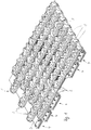
- Each crawler track is formed by a plurality of chain belts 3 that run around in the assembled state and extend parallel to one another in the chain running direction, as well as by a plurality of chain web arrangements 1 extending transversely to the chain running direction and arranged parallel to one another, which are connected to the chain belts 3.
- Each chain stay arrangement 1 according to FIGS Figs. 1 to 4 has a chain web, which is described in more detail below, and a track bracket 2.
- Fig. 1 Based on Fig. 1 it can be seen that the total of five chain belts 3, two of which have a greater width than the others, are joined together at their opposite ends via a chain lock 4 each to form a circumferential chain belt 3.
- a chain web of each chain web arrangement 1 is arranged in the area of an outside of the chain belts 3, whereas the track bracket 2 of each chain web arrangement 1 faces an opposite inner side of the respective one Chain web protrudes.
- Each chain web of the chain web arrangement 1 has a vulcanized rubber profile 6 in the area of its outwardly directed upper side.
- Each track bracket 2 of each chain stay arrangement 1 protrudes opposite to the rubber profile 6 inwardly from the respective chain stay.
- Each chain web is formed by a chain web profile 5, which is made of an aluminum alloy in the illustrated embodiment.
- the chain stay profile 5 extends over an entire length of the chain stay and thus the chain stay arrangement 1.
- On an outside of the chain stay profile 5, as shown in FIG Fig. 3 and 4th It can be clearly seen that the rubber profile 6 is vulcanized on over the entire length of the chain web profile 5.
- Each chain web profile 5 is provided in the area of its underside, which rests in the assembled state on an outside of the chain belts 3, with fastening receptacles 9, which in the present case are designed as threaded holes.
- the chain web profile 5 is made as an extruded profile from the aluminum alloy and has over its entire length below the rubber profile 5 (see Fig. 3 and 4th ) a longitudinal profile which forms a square, lower end of the chain stay profile 5 in cross section.
- the longitudinal profile is accordingly designed as an approximately square-shaped rail section.
- the rail section In the area of its underside, the rail section has a flat support surface which serves to support the chain web profile 5 on the chain belts 3.
- a longitudinal groove 7 is provided on both sides, which also form partial sections of the longitudinal profile of the chain web profile 5.
- the longitudinal grooves 7 extend over an entire length of the chain web profile 5 and define an undercut, which is described in more detail below, for a complementary longitudinal profile of the track bracket 2.
- the track bracket 2 has, in a basically known manner, two track horns which, when the drive chain is in operation, flank running wheels, as well as a drive wheel and a tensioning wheel, on both sides.
- the track bracket 2 is produced as a one-piece component from a metallic material, in the present case from a steel alloy.
- the track bracket 2 has a receiving area in the area of its upper side facing the chain web profile 5, which is designed as a longitudinal profile complementary to the longitudinal profile of the chain web profile 5 in the form of a substantially C-shaped, groove or channel-shaped groove cross-section. This longitudinal profile of the track bracket 2 extends over an entire length of the track bracket 2 and is open to both end faces of the track bracket 2.
- this groove-shaped or channel-shaped longitudinal profile has of the track bracket 2 has a flat bottom surface and two side walls projecting upward at right angles from the bottom surface on opposite sides, each of which ends in a longitudinal web 8 pointing inward toward the opposite longitudinal side.
- a cross section of the two longitudinal webs 8 is matched to a cross section of the longitudinal grooves 7 on their inner side facing the chain web profile 5, so that the longitudinal webs 8 engage positively in the longitudinal grooves 7 and thus together with the longitudinal grooves 7 form an undercut in the vertical direction of the track bracket 2.
- the longitudinal sides of the groove or channel-shaped longitudinal profile of the track bracket 2 extend parallel and flat to opposite, outer longitudinal sides of the rail section of the chain web profile 5, so that in the assembled state an inner contour of the groove or channel-shaped longitudinal profile of the track bracket 2 is flat on all sides on the complementary outer contour of the Rail section of the chain web profile 5 rests.
- the longitudinal webs 8 engage in the longitudinal grooves 7.
- the track bracket 2 which is designed as a separate, one-piece steel component, is heated to a temperature in the range of approximately 100.degree.
- the chain web profile 5 in the present case with the aid of dry ice, is cooled to a temperature which causes a certain shrinkage of the dimensions of the chain web profile 5.
- the heating of the track bracket 2 leads to a certain widening and expansion of the track bracket 2, it is possible to move the track bracket 2 in the heated state from one end face of the chain stay profile 5 onto the cooled chain stay profile 5 in the area of the longitudinal profile of the chain stay profile, which is designed as a rail section 5 up to the middle of the chain stay profile 5, in particular to push it on or open it, until the track bracket 2 is based on the Fig. 2 has reached a recognizable central position.
- the temperature is equalized, preferably to room temperature, which inevitably results in a tension of the two components, ie the chain web profile 5 and the track bracket 2, relative to one another due to the opposing material shrinkage or material expansion of the two components.
- the track bracket 2 and the chain stay profile 5 are consequently pressed together after the temperature has been equalized.
- the undercut on both sides formed by the longitudinal grooves 7 and the longitudinal webs 8 causes, on the one hand, a form-fitting securing of the track bracket 2 on the chain stay profile 5 and, on the other hand, the maintenance of the pretension due to the compression between the chain stay profile 5 and the track bracket 2. Due to the compression, the groove- or channel-shaped longitudinal profiling of the track bracket 2 over its entire inner contour, at least largely flat, on the outer contour of the longitudinal profiling of the chain web profile 5, which is designed as a rail section.
- the track bracket 2 is additionally fixed to the chain stay profile 5 with the aid of screw connections during the manufacture of the chain stay arrangement 1.
- the rubber profile 6 is vulcanized onto the outside of the chain web profile 5 above the longitudinal profile designed as a rail section, as shown in FIG Figs. 2 to 4 is recognizable.
- the chain web arrangement 1 completed in this way can then be screwed to the chain belts 3 in a basically known manner in order to be able to assemble the drive chain as a whole.
Landscapes
- Engineering & Computer Science (AREA)
- Chemical & Material Sciences (AREA)
- Combustion & Propulsion (AREA)
- Transportation (AREA)
- Mechanical Engineering (AREA)
- Devices For Conveying Motion By Means Of Endless Flexible Members (AREA)
Abstract
Description
- Die Erfindung betrifft eine Kettensteganordnung für eine Laufwerkskette eines Kettenfahrzeugs mit einem Kettenstegprofil aus einer Metalllegierung, sowie mit einem Spurbügel, der in montiertem Zustand fest mit dem Kettenstegprofil verbunden ist. Die Erfindung betrifft zudem ein Verfahren zur Herstellung einer solchen Kettensteganordnung für eine Laufwerkskette eines Kettenfahrzeugs.
- Eine derartige Kettensteganordnung ist aus der
DE 10 2013 204 627 B4 bekannt. Die bekannte Kettensteganordnung weist ein Kettenstegprofil sowie einen Spurbügel auf, der über Schraubverbindungen fest mit dem Kettenstegprofil verbindbar ist. - Aufgabe der Erfindung ist es, eine Kettensteganordnung sowie ein Verfahren der eingangs genannten Art zu schaffen, die eine verbesserte Biegesteifigkeit für die Kettensteganordnung bewirken.
- Für die Kettensteganordnung wird die der Erfindung zugrunde liegende Aufgabe dadurch gelöst, dass der Spurbügel und das Kettenstegprofil mit zueinander komplementären Längsprofilierungen versehen sind, die orthogonal zu ihrer Längsrichtung wenigstens einen Hinterschnitt bilden, der den Spurbügel orthogonal zur Längsrichtung formschlüssig an dem Kettenstegprofil sichert. Unter der orthogonalen Ausrichtung ist eine Orthogonale relativ zu einer Verbindungsfläche zwischen Kettenstegprofil und Spurbügel zu verstehen, die parallel oder koplanar zu einer Kettenbandebene der Laufwerkskette verläuft. Der erfindungsgemäße Formschluss verhindert demzufolge, dass der Spurbügel in Hochrichtung der Kettensteganordnung und damit in Hochrichtung des Kettenstegprofiles von dem Kettenstegprofil entfernt werden kann. Die formschlüssige Sicherung erfolgt vorzugsweise durch zueinander komplementäre, C- oder T-förmige Längsprofilierungen. Die formschlüssige Sicherung des Spurbügels an dem Kettenstegprofil gewährleistet eine durchgängig flächige, besonders innige Verbindung zwischen dem Spurbügel und dem Kettenstegprofil, so dass der Spurbügel über seine gesamte Länge zur Versteifung des Kettenstegprofiles beiträgt. Ein Durchbiegen des Kettenstegprofiles im Bereich des Spurbügels wird demzufolge vermieden, wodurch sich insgesamt die Biegesteifigkeit der Kettensteganordnung vergrößert. Zudem ergibt sich erfindungsgemäß eine Vorspannung zwischen dem Spurbügel und dem Kettenstegprofil, so dass eine zusätzliche Schraubverbindung zwischen dem Kettenstegprofil und dem Spurbügel ebenfalls in ausreichender Vorspannung erhalten bleibt. Beschädigungen der Schraubverbindungen können so vermieden werden. Neben der Verhinderung des Verlustes einer Vorspannungskraft und der Verhinderung der Durchbiegung des Kettenstegprofiles unter dem Spurbügel wird auch eine erhöhte Dichtheit an den Verbindungsstellen zwischen dem Spurbügel und dem Kettenstegprofil erzielt, wodurch das Eindringen von Schmutz verhindert werden kann. Die erfindungsgemäße Lösung eignet sich in besonders vorteilhafter Weise für Kettenfahrzeuge, die auf steinigem oder schwer befahrbarem Untergrund als Arbeitsfahrzeuge betrieben werden. Dabei weisen die Kettenstege vorzugsweise eine Gummiprofilierung im Bereich einer Aufstandsfläche auf, d. h. die Kettenstege sind mit einer Gummierung versehen. In gleicher Weise ist die erfindungsgemäße Lösung aber auch für Pistenraupen einsetzbar, die auf Schnee betrieben werden. Derartige Kettenlaufwerke weisen Kettenstege auf, die ausschließlich metallisch, insbesondere aus einer Aluminiumlegierung und aus Stahl, hergestellt sind und damit keine Gummierung aufweisen.
- In Ausgestaltung der Erfindung sind der Spurbügel auf einer dem Kettenstegprofil zugewandten Längsseite mit einer im Querschnitt nut- oder kanalförmigen Längsprofilierung und das Kettenstegprofil mit einer komplementär schienenförmigen Längsprofilierung versehen. Die Längsprofilierungen greifen demzufolge in Hochrichtung der Kettensteganordnung gesehen formschlüssig ineinander ein.
- In weiterer Ausgestaltung der Erfindung sind die Längsprofilierungen jeweils einstückig an dem Spurbügel und dem Kettenstegprofil angeformt. Vorzugsweise erstreckt sich die Längsprofilierung an dem Kettenstegprofil über eine gesamte Länge des Kettenstegprofiles, so dass das Kettenstegprofil vorteilhaft als Strangpressprofil aus einer Leichtmetalllegierung, insbesondere einer Aluminiumlegierung, hergestellt werden kann.
- In weiterer Ausgestaltung der Erfindung liegen die zueinander komplementären Längsprofilierungen des Spurbügels und des Kettenstegprofiles in formschlüssig gesicherter Montagestellung zumindest weitgehend flächig aneinander. Vorzugsweise liegen die komplementären Längsprofilierungen unter Vorspannung flächig aneinander, wodurch sich die zuvor bereits beschriebenen Vorteile ergeben.
- In weiterer Ausgestaltung der Erfindung ist der Spurbügel in seiner an der Längsprofilierung des Kettenstegprofils formschlüssig gesicherten Montagestellung zusätzlich kraft- oder stoffschlüssig mit dem Kettenstegprofil verbunden. Der Spurbügel ist vorzugsweise mit dem Kettenstegprofil verpresst oder verschraubt oder verklebt. Die entsprechenden Verbindungsvarianten können auch miteinander kombiniert werden.
- In weiterer Ausgestaltung der Erfindung umgreift die Längsprofilierung des Spurbügels die Längsprofilierung des Kettenstegprofiles beidseitig außen formschlüssig. Dadurch ergibt sich ein C-förmiges Umgreifen des Spurbügels relativ zu dem Kettenstegprofil.
- In weiterer Ausgestaltung der Erfindung ist die Längsprofilierung des Kettenstegprofils über eine gesamte Länge des Kettenstegprofils durchgängig erstreckt. Diese Ausgestaltung ist vorteilhaft, falls das Kettenstegprofil - wie zuvor bereits ausgeführt - in einem Strangpressverfahren hergestellt wird. Denn dann kann die Längsprofilierung gemeinsam mit der Herstellung des Kettenstegprofiles zwangsläufig mit ausgeformt werden.
- In weiterer Ausgestaltung der Erfindung ist die komplementäre Längsprofilierung des Spurbügels über seine gesamte Länge durchgängig erstreckt. Diese Ausgestaltung hat den Vorteil, dass die Längsprofilierung des Spurbügels von einer Stirnseite her auf das Kettenstegprofil aufgeschoben, insbesondere aufgepresst, und über seine gesamte Länge mit dem Kettenstegprofil fest verbunden wird.
- In weiterer Ausgestaltung der Erfindung ist das Kettenstegprofil auf seiner zu dem Spurbügel abgewandten Seite mit einer elastisch nachgiebigen Profilierung, insbesondere aus einem Elastomermaterial oder einem thermoplastischen Elastomermaterial, versehen. Die elastisch nachgiebige Profilierung ist vorzugsweise auf die dem Spurbügel abgewandte Seite des Kettenstegprofiles aufvulkanisiert.
- Für das Verfahren zur Herstellung einer Kettensteganordnung für eine Laufwerkskette eines Kettenfahrzeugs wie zuvor beschrieben wird die der Erfindung zugrundeliegende Aufgabe dadurch gelöst, dass das Kettenstegprofil abgekühlt wird, dass der Spurbügel erhitzt wird, und dass anschließend der Spurbügel in erhitztem Zustand mit seiner Längsprofilierung auf die komplementäre Längsprofilierung des abgekühlten Kettenstegprofiles in Längsrichtung aufgesteckt wird, und dass abschließend ein gemeinsamer Temperaturausgleich zwischen dem Kettenstegprofil und dem Spurbügel vorgesehen wird. Das Aufstecken erfolgt vorzugsweise durch Aufschieben oder Aufziehen. Das erfindungsgemäße Abkühlen führt zu einer geringfügigen Schrumpfung des Kettenstegprofiles. Das Erhitzen des Spurbügels führt zu einer gewissen Ausdehnung und Aufweitung des Spurbügels. Dadurch ergibt sich zwischen den zueinander komplementären Längsprofilierungen eine Spielpassung, die ein gleitbewegliches Aufstecken der Längsprofilierungen relativ zueinander ermöglichen, solange der Spurbügel und das Kettenstegprofil in den unterschiedlichen Temperaturzuständen befindlich sind. Das anschließende, gemeinsame Abkühlen nach dem Aufschieben oder Aufziehen des Spurbügels auf das Kettenstegprofil führt zwangsläufig zu einem Schrumpfen des aufgrund der Erhitzung aufgeweiteten Spurbügels und einem Ausdehnen des durch die Abkühlung geschrumpften Kettenstegprofils. Hierdurch ergibt sich zwangsläufig eine flächige Verpressung zwischen dem Spurbügel und dem Kettenstegprofil, wodurch die formschlüssige Verbindung zwischen den Längsprofilierungen des Kettenstegprofiles und des Spurbügels zusätzlich einer Vorspannung unterliegt.
- Weitere Vorteile und Merkmale der Erfindung ergeben sich aus den Ansprüchen sowie aus der nachfolgenden Beschreibung eines bevorzugten Ausführungsbeispiels der Erfindung, das anhand der Zeichnungen dargestellt ist.
- Fig. 1
- zeigt ausschnittsweise in perspektivischer Darstellung einen Teilbereich einer Laufwerkskette für ein Kettenlaufwerk eines Kettenfahrzeugs,
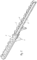
- Fig. 2
- in vergrößerter, teilweise aufgeschnittener Darstellung eine Ausführungsform einer erfindungsgemäßen Kettensteganordnung für die Laufwerkskette gemäß
Fig. 1 , - Fig. 3
- in weiter vergrößerter Darstellung einen Ausschnitt der Kettensteganordnung gemäß
Fig. 2 und - Fig. 4
- einen Querschnitt durch die Kettensteganordnung gemäß
Fig. 3 auf Höhe eines Spurbügels. - Ein Kettenfahrzeug weist ein Kettenlaufwerk auf, das auf gegenüberliegenden Längsseiten eines Fahrzeugrahmens mit jeweils einer Laufwerkskette versehen ist. Jede Laufwerkskette wird gebildet durch mehrere, in montiertem Zustand umlaufende Kettenbänder 3, die parallel zueinander in Kettenlaufrichtung erstreckt sind, sowie durch eine Vielzahl von quer zur Kettenlaufrichtung erstreckten und parallel zueinander angeordneten Kettensteganordnungen 1, die mit den Kettenbändern 3 verbunden sind. Jede Kettensteganordnung 1 gemäß den
Fig. 1 bis 4 weist einen nachfolgend näher beschriebenen Kettensteg sowie einen Spurbügel 2 auf. - Anhand der
Fig. 1 ist erkennbar, dass die insgesamt fünf Kettenbänder 3, von denen zwei eine größere Breite aufweisen als die übrigen, an ihren gegenüberliegenden Enden über jeweils ein Kettenschloss 4 zu jeweils einem umlaufenden Kettenband 3 zusammengefügt sind. - Wie anhand der
Fig. 1 erkennbar ist, ist ein Kettensteg jeder Kettensteganordnung 1 im Bereich einer Außenseite der Kettenbänder 3 angeordnet, wohingegen der Spurbügel 2 jeder Kettensteganordnung 1 zu einer gegenüberliegenden Innenseite hin von dem jeweiligen Kettensteg abragt. Jeder Kettensteg der Kettensteganordnung 1 weist im Bereich seiner nach außen gerichteten Oberseite eine aufvulkanisierte Gummiprofilierung 6 auf. Jeder Spurbügel 2 jeder Kettensteganordnung 1 ragt entgegengesetzt zu der Gummiprofilierung 6 nach innen von dem jeweiligen Kettensteg ab. - Jeder Kettensteg wird durch ein Kettenstegprofil 5 gebildet, das beim dargestellten Ausführungsbeispiel aus einer Aluminiumlegierung hergestellt ist. Das Kettenstegprofil 5 erstreckt sich über eine gesamte Länge des Kettensteges und damit der Kettensteganordnung 1. Auf einer Außenseite des Kettenstegprofils 5 ist, wie anhand der
Fig. 3 und4 gut erkennbar ist, die Gummiprofilierung 6 über die gesamte Länge des Kettenstegprofils 5 aufvulkanisiert. - Jedes Kettenstegprofil 5 ist im Bereich seiner Unterseite, die in montiertem Zustand auf einer Außenseite der Kettenbänder 3 aufliegt, mit Befestigungsaufnahmen 9 versehen, die vorliegend als Gewindebohrungen ausgeführt sind.
- Das Kettenstegprofil 5 ist als Strangpressprofil aus der Aluminiumlegierung hergestellt und weist über seine gesamte Länge unterhalb der Gummiprofilierung 5 (siehe
Fig. 3 und4 ) eine Längsprofilierung auf, die im Querschnitt einen vierkantförmigen, unteren Abschluss des Kettenstegprofils 5 bildet. Die Längsprofilierung ist demzufolge als etwa vierkantförmiger Schienenabschnitt gestaltet. Der Schienenabschnitt weist im Bereich seiner Unterseite eine ebene Auflagefläche auf, die zur Auflage des Kettenstegprofils 5 auf den Kettenbändern 3 dient. An einem oberen Endbereich des Schienenabschnittes ist beidseitig jeweils eine Längsnut 7 vorgesehen, die ebenfalls Teilabschnitte der Längsprofilierung des Kettenstegprofiles 5 bilden. Die Längsnuten 7 erstrecken sich über eine gesamte Länge des Kettenstegprofils 5 und definieren einen nachfolgend noch näher beschriebenen Hinterschnitt für eine komplementäre Längsprofilierung des Spurbügels 2. - Der Spurbügel 2 weist in grundsätzlich bekannter Weise zwei Spurhörner auf, die im Betrieb der Laufwerkskette Laufräder, sowie ein Antriebsrad und ein Spannrad jeweils beidseitig flankieren. Der Spurbügel 2 ist als einteiliges Bauteil aus einem metallischen Werkstoff, vorliegend aus einer Stahllegierung, hergestellt. Der Spurbügel 2 weist im Bereich seiner dem Kettenstegprofil 5 zugewandten Oberseite einen Aufnahmebereich auf, der als zu der Längsprofilierung des Kettenstegprofils 5 komplementäre Längsprofilierung in Form eines im Wesentlichen C-förmigen, nut- oder kanalförmigen Nutquerschnitts gestaltet ist. Diese Längsprofilierung des Spurbügels 2 erstreckt sich über eine gesamte Länge des Spurbügels 2 und ist zu beiden Stirnseiten des Spurbügels 2 hin offen. Komplementär zu der zuvor beschriebenen Längsprofilierung des Kettenstegprofils 5 weist diese nut- oder kanalförmige Längsprofilierung des Spurbügels 2 eine ebene Bodenfläche sowie zwei zu gegenüberliegenden Seiten von der Bodenfläche aus rechtwinklig nach oben abragende Seitenwandungen auf, die in jeweils einem nach innen zu der gegenüberliegenden Längsseite hin weisenden Längssteg 8 enden. Ein Querschnitt der beiden Längsstege 8 ist auf ihrer dem Kettenstegprofil 5 zugewandten Innenseite auf einen Querschnitt der Längsnuten 7 abgestimmt, so dass die Längsstege 8 formschlüssig in die Längsnuten 7 eingreifen und somit gemeinsam mit den Längsnuten 7 einen Hinterschnitt in Hochrichtung des Spurbügels 2 bilden. Die Längsseiten der nut- oder kanalförmigen Längsprofilierung des Spurbügels 2 erstrecken sich parallel und flächig zu gegenüberliegenden, außenseitigen Längsseiten des Schienenabschnittes des Kettenstegprofils 5, so dass in montiertem Zustand eine Innenkontur der nut- oder kanalförmigen Längsprofilierung des Spurbügels 2 allseits flächig an der komplementären Außenkontur des Schienenabschnitts des Kettenstegprofils 5 anliegt. Die Längsstege 8 greifen in die Längsnuten 7 ein.
- Für eine Montage des Spurbügels 2 an dem Kettenstegprofil 5 wird der als separates, einteiliges Stahlbauteil gestaltete Spurbügel 2 auf eine Temperatur im Bereich von etwa 100°C erhitzt. Gleichzeitig wird das Kettenstegprofil 5, vorliegend mit Hilfe von Trockeneis, auf eine Temperatur abgekühlt, die eine gewisse Schrumpfung der Abmessungen des Kettenstegprofils 5 bewirkt. Da gleichzeitig die Erhitzung des Spurbügels 2 zu einer gewissen Aufweitung und Ausdehnung des Spurbügels 2 führt, ist es möglich, den Spurbügel 2 in dem erhitzten Zustand von einer Stirnseite des Kettenstegprofils 5 her auf das abgekühlte Kettenstegprofil 5 im Bereich der als Schienenabschnitt ausgeführten Längsprofilierung des Kettenstegprofils 5 bis zur Mitte des Kettenstegprofils 5 hin aufzustecken, insbesondere aufzuschieben oder aufzuziehen, bis der Spurbügel 2 seine anhand der
Fig. 2 erkennbare Mittellage erreicht hat. In dieser Montagestellung erfolgt nun eine Temperaturangleichung, vorzugsweise auf Raumtemperatur, wodurch sich zwangsläufig aufgrund der sich gegensinnig ergebenden Materialschrumpfungen bzw. Materialausdehnungen beider Bauteile eine Verspannung der beiden Bauteile, d. h. des Kettenstegprofils 5 und des Spurbügels 2, relativ zueinander ergibt. Der Spurbügel 2 und das Kettenstegprofil 5 sind demzufolge nach der Temperaturangleichung miteinander verpresst. Der durch die Längsnuten 7 und die Längsstege 8 gebildete, beidseitige Hinterschnitt bewirkt zum einen eine formschlüssige Sicherung des Spurbügels 2 an dem Kettenstegprofil 5 und zum anderen die Aufrechterhaltung der Vorspannung aufgrund der Verpressung zwischen Kettenstegprofil 5 und Spurbügel 2. Aufgrund der Verpressung liegt die nut- oder kanalförmige Längsprofilierung des Spurbügels 2 über ihre gesamte Innenkontur zumindest weitgehend flächig an der Außenkontur der als Schienenabschnitt gestalteten Längsprofilierung des Kettenstegprofiles 5 fest an. - Im Anschluss an diese Verpressung des Spurbügels 2 relativ zum Kettenstegprofil 5 wird bei der Herstellung der Kettensteganordnung 1 der Spurbügel 2 zusätzlich mit Hilfe von Schraubverbindungen an dem Kettenstegprofil 5 fixiert. Abschließend wird die Gummiprofilierung 6 auf die Außenseite des Kettenstegprofils 5 oberhalb der als Schienenabschnitt gestalteten Längsprofilierung aufvulkanisiert, wie anhand der
Fig. 2 bis 4 erkennbar ist. Die so fertiggestellte Kettensteganordnung 1 kann dann in grundsätzlich bekannter Weise mit den Kettenbändern 3 verschraubt werden, um die Laufwerkskette insgesamt montieren zu können. Gleiches gilt für die in identischer Weise montierten und hergestellten weiteren Kettensteganordnungen 1.
Claims (11)
- Kettensteganordnung (1) für eine Laufwerkskette eines Kettenfahrzeugs mit einem Kettenstegprofil (5) aus einer Metalllegierung, sowie mit einem Spurbügel (2), der in montiertem Zustand fest mit dem Kettenstegprofil (5) verbunden ist, dadurch gekennzeichnet, dass der Spurbügel (2) und das Kettenstegprofil (5) mit zueinander komplementären Längsprofilierungen versehen sind, die orthogonal zu ihrer Längsrichtung wenigstens einen Hinterschnitt bilden, der den Spurbügel (2) orthogonal zur Längsrichtung formschlüssig an dem Kettenstegprofil (5) sichert.
- Kettensteganordnung (1) nach Anspruch 1, dadurch gekennzeichnet, dass der Spurbügel (2) auf einer dem Kettenstegprofil (5) zugewandten Längsseite mit einer im Querschnitt nut- oder kanalförmigen Längsprofilierung und das Kettenstegprofil (5) mit einer komplementär schienenförmigen Längsprofilierung versehen sind.
- Kettensteganordnung (1) nach Anspruch 1 oder 2, dadurch gekennzeichnet, dass die Längsprofilierungen jeweils einstückig an dem Spurbügel (2) und dem Kettenstegprofil (5) ausgeformt sind.
- Kettensteganordnung (1) nach einem der vorhergehenden Ansprüche, dadurch gekennzeichnet, dass die zueinander komplementären Längsprofilierungen des Spurbügels (2) und des Kettenstegprofils (5) in formschlüssig gesicherter Montagestellung zumindest weitgehend flächig aneinanderliegen.
- Kettensteganordnung (1) nach einem der vorhergehenden Ansprüche, dadurch gekennzeichnet, dass der Spurbügel (2) in seiner an der Längsprofilierung des Kettenstegprofils (5) formschlüssig gesicherten Montagestellung zusätzlich kraft- oder stoffschlüssig mit dem Kettenstegprofil (5) verbunden ist.
- Kettensteganordnung (1) nach einem der vorhergehenden Ansprüche, dadurch gekennzeichnet, dass die Längsprofilierung des Spurbügels (2) die Längsprofilierung des Kettenstegprofils (5) beidseitig außen formschlüssig umgreift.
- Kettensteganordnung (1) nach einem der vorhergehenden Ansprüche, dadurch gekennzeichnet, dass die Längsprofilierung des Kettenstegprofils (5) über eine gesamte Länge des Kettenstegprofils (5) durchgängig erstreckt ist.
- Kettensteganordnung (1) nach Anspruch 7, dadurch gekennzeichnet, dass die komplementäre Längsprofilierung des Spurbügels (2) über seine gesamte Länge durchgängig erstreckt ist.
- Kettensteganordnung (1) nach einem der vorhergehenden Ansprüche, dadurch gekennzeichnet, dass die Querschnitte der Längsprofilierungen des Spurbügels (2) und des Kettenstegprofils (5) derart aufeinander abgestimmt sind, dass sich eine zumindest weitgehend flächige Gleitführung für die Längsprofilierung relativ zueinander ergibt.
- Kettensteganordnung (1) nach einem der vorhergehenden Ansprüche, dadurch gekennzeichnet, dass das Kettenstegprofil (5) auf seiner zu dem Spurbügel (2) abgewandten Seite mit einer elastisch nachgiebigen Profilierung (6), insbesondere aus einem Elastomermaterial oder einem thermoplastischen Elastomermaterial, versehen ist.
- Verfahren zur Herstellung einer Kettensteganordnung (1) für eine Laufwerkskette eines Kettenfahrzeugs nach einem der vorhergehenden Ansprüche, dadurch gekennzeichnet, dass das Kettenstegprofil (5) abgekühlt wird, dass der Spurbügel (2) erhitzt wird, und dass anschließend der Spurbügel (2) in erhitztem Zustand mit seiner Längsprofilierung auf die komplementäre Längsprofilierung des abgekühlten Kettenstegprofils (5) in Längsrichtung aufgesteckt wird, und dass abschließend ein gemeinsamer Temperaturausgleich zwischen dem Kettenstegprofil (5) und dem Spurbügel (2) vorgesehen wird.
Applications Claiming Priority (1)
| Application Number | Priority Date | Filing Date | Title |
|---|---|---|---|
| DE102019220531.3A DE102019220531B4 (de) | 2019-12-23 | 2019-12-23 | Kettensteganordnung für eine Laufwerkskette eines Kettenfahrzeugs und Verfahren zur Herstellung einer derartigen Kettensteganordnung |
Publications (2)
| Publication Number | Publication Date |
|---|---|
| EP3842324A1 true EP3842324A1 (de) | 2021-06-30 |
| EP3842324B1 EP3842324B1 (de) | 2023-08-16 |
Family
ID=73020132
Family Applications (1)
| Application Number | Title | Priority Date | Filing Date |
|---|---|---|---|
| EP20203955.8A Active EP3842324B1 (de) | 2019-12-23 | 2020-10-26 | Kettensteganordnung für eine laufwerkskette eines kettenfahrzeugs und verfahren zur herstellung einer derartigen kettensteganordnung |
Country Status (2)
| Country | Link |
|---|---|
| EP (1) | EP3842324B1 (de) |
| DE (1) | DE102019220531B4 (de) |
Citations (5)
| Publication number | Priority date | Publication date | Assignee | Title |
|---|---|---|---|---|
| CN101264773A (zh) * | 2008-03-27 | 2008-09-17 | 江春立 | 履带式行动机具的履带板 |
| DE102013204627A1 (de) * | 2013-03-15 | 2014-09-18 | Kässbohrer Geländefahrzeug AG | Kettensteganordnung, Laufwerkskette und Kettenlaufwerk für eine Pistenraupe |
| DE102015208614B3 (de) * | 2015-05-08 | 2016-09-22 | Kässbohrer Geländefahrzeug AG | Kettenlaufwerk für ein Pistenpflegefahrzeug und Pistenpflegefahrzeug mit einem Kettenlaufwerk und Arbeitsverfahren eines Kettenlaufwerks eines Pistenpflegefahrzeugs |
| EP3213983A1 (de) * | 2015-04-15 | 2017-09-06 | Kässbohrer Geländefahrzeug AG | Kettensteganordnung einer laufwerkskette einer pistenraupe und verfahren zur herstellung eines kettenstegprofils für eine derartige kettensteganordnung |
| DE102017203363A1 (de) * | 2017-03-02 | 2018-09-06 | Contitech Transportbandsysteme Gmbh | Fahrwerkkette, insbesondere Bogie-Kette |
Family Cites Families (3)
| Publication number | Priority date | Publication date | Assignee | Title |
|---|---|---|---|---|
| US5547268A (en) * | 1992-02-28 | 1996-08-20 | Hansen; David W. | Traction device for tracked vehicle |
| WO2011127554A1 (en) * | 2010-04-16 | 2011-10-20 | Rolic Invest Sarl | Cross-links for a track of a tracked vehicle |
| DE102014001006A1 (de) * | 2014-01-29 | 2015-07-30 | Hans Hall Gmbh | Traktionskette für eine Raupenkette eines Kettenfahrzeugs sowie Bausatz für eine Raupenkette |
-
2019
- 2019-12-23 DE DE102019220531.3A patent/DE102019220531B4/de not_active Expired - Fee Related
-
2020
- 2020-10-26 EP EP20203955.8A patent/EP3842324B1/de active Active
Patent Citations (6)
| Publication number | Priority date | Publication date | Assignee | Title |
|---|---|---|---|---|
| CN101264773A (zh) * | 2008-03-27 | 2008-09-17 | 江春立 | 履带式行动机具的履带板 |
| DE102013204627A1 (de) * | 2013-03-15 | 2014-09-18 | Kässbohrer Geländefahrzeug AG | Kettensteganordnung, Laufwerkskette und Kettenlaufwerk für eine Pistenraupe |
| DE102013204627B4 (de) | 2013-03-15 | 2017-10-12 | Kässbohrer Geländefahrzeug AG | Kettensteganordnung, Laufwerkskette und Kettenlaufwerk für eine Pistenraupe |
| EP3213983A1 (de) * | 2015-04-15 | 2017-09-06 | Kässbohrer Geländefahrzeug AG | Kettensteganordnung einer laufwerkskette einer pistenraupe und verfahren zur herstellung eines kettenstegprofils für eine derartige kettensteganordnung |
| DE102015208614B3 (de) * | 2015-05-08 | 2016-09-22 | Kässbohrer Geländefahrzeug AG | Kettenlaufwerk für ein Pistenpflegefahrzeug und Pistenpflegefahrzeug mit einem Kettenlaufwerk und Arbeitsverfahren eines Kettenlaufwerks eines Pistenpflegefahrzeugs |
| DE102017203363A1 (de) * | 2017-03-02 | 2018-09-06 | Contitech Transportbandsysteme Gmbh | Fahrwerkkette, insbesondere Bogie-Kette |
Also Published As
| Publication number | Publication date |
|---|---|
| DE102019220531A1 (de) | 2021-06-24 |
| EP3842324B1 (de) | 2023-08-16 |
| DE102019220531B4 (de) | 2021-08-26 |
Similar Documents
| Publication | Publication Date | Title |
|---|---|---|
| DE4210456C2 (de) | Querverbindung für Profilstäbe mittels Zuggliedern | |
| DE102005043698A1 (de) | Seitenschweller einer Kraftwagenkarosserie | |
| WO2013107683A1 (de) | Dachreling für ein kraftfahrzeug | |
| EP3339146B1 (de) | Kettensteganordnung für eine laufwerkskette eines kettenfahrzeugs | |
| EP0100824B1 (de) | Verbundprofil, insbesondere für Rahmen von Fenstern, Türen und Fassadenelementen | |
| EP3081462B1 (de) | Kettensteganordnung einer laufwerkskette einer pistenraupe, verfahren zur herstellung eines kettenstegprofils für eine derartige kettensteganordnung und laufwerkskette für eine pistenraupe | |
| DE102011086790A1 (de) | Wischblattvorrichtung mit einem zumindest teilweise aus einem Faserverbundwerkstoff gebildeten Federkern | |
| EP1346879B1 (de) | Einstiegleiste für einen Kraftfahrzeugschweller | |
| EP1880924A2 (de) | Träger als Längs- bzw. Querträger in einem Kraftfahrzeug | |
| DE202012012603U1 (de) | Fahrzeugrahmen | |
| DE102019220531B4 (de) | Kettensteganordnung für eine Laufwerkskette eines Kettenfahrzeugs und Verfahren zur Herstellung einer derartigen Kettensteganordnung | |
| DE102008020988A1 (de) | Wärmeisolierendes Rahmenprofil für die Herstellung von Tür- und Fensterrahmen | |
| AT505737B1 (de) | Vorrichtung zum verbinden zweier stumpf stossender bauteile | |
| DE102012000827A1 (de) | Dachreling für ein Kraftfahrzeug sowie Verfahren zur Befestigung einer Abdeckung einer Dachreling | |
| EP2144829B1 (de) | Mitnehmer für kettenförderer, insbesondere zur befestigung von kratzeisen | |
| EP3945007B1 (de) | Kettensteganordnung für eine laufwerkskette eines kettenfahrzeugs | |
| EP3842325B1 (de) | Kettensteg für ein kettenfahrzeug und verfahren zur herstellung eines solchen kettensteges | |
| EP3798108A1 (de) | Kettenanordnung für eine pistenraupe | |
| EP3031704B1 (de) | Gleiskette | |
| DE102008009179B4 (de) | Verfahren zur Herstellung einer Zug-Druck-Strebe für eine Fahrzeugkarosserie | |
| DE102009011022A1 (de) | Verbindungsanordnung für einen Träger einer Karosserie eines Kraftwagens | |
| DE102011106400A1 (de) | Bauteil aus mindestens zwei Profilelementen | |
| DE20304437U1 (de) | Zahnkette | |
| DE202006002337U1 (de) | Laufschienensystem | |
| DE102004055556B4 (de) | Verbindungselement für Profile |
Legal Events
| Date | Code | Title | Description |
|---|---|---|---|
| PUAI | Public reference made under article 153(3) epc to a published international application that has entered the european phase |
Free format text: ORIGINAL CODE: 0009012 |
|
| STAA | Information on the status of an ep patent application or granted ep patent |
Free format text: STATUS: THE APPLICATION HAS BEEN PUBLISHED |
|
| AK | Designated contracting states |
Kind code of ref document: A1 Designated state(s): AL AT BE BG CH CY CZ DE DK EE ES FI FR GB GR HR HU IE IS IT LI LT LU LV MC MK MT NL NO PL PT RO RS SE SI SK SM TR |
|
| STAA | Information on the status of an ep patent application or granted ep patent |
Free format text: STATUS: REQUEST FOR EXAMINATION WAS MADE |
|
| 17P | Request for examination filed |
Effective date: 20211216 |
|
| RBV | Designated contracting states (corrected) |
Designated state(s): AL AT BE BG CH CY CZ DE DK EE ES FI FR GB GR HR HU IE IS IT LI LT LU LV MC MK MT NL NO PL PT RO RS SE SI SK SM TR |
|
| GRAP | Despatch of communication of intention to grant a patent |
Free format text: ORIGINAL CODE: EPIDOSNIGR1 |
|
| STAA | Information on the status of an ep patent application or granted ep patent |
Free format text: STATUS: GRANT OF PATENT IS INTENDED |
|
| INTG | Intention to grant announced |
Effective date: 20230405 |
|
| GRAS | Grant fee paid |
Free format text: ORIGINAL CODE: EPIDOSNIGR3 |
|
| GRAA | (expected) grant |
Free format text: ORIGINAL CODE: 0009210 |
|
| STAA | Information on the status of an ep patent application or granted ep patent |
Free format text: STATUS: THE PATENT HAS BEEN GRANTED |
|
| AK | Designated contracting states |
Kind code of ref document: B1 Designated state(s): AL AT BE BG CH CY CZ DE DK EE ES FI FR GB GR HR HU IE IS IT LI LT LU LV MC MK MT NL NO PL PT RO RS SE SI SK SM TR |
|
| REG | Reference to a national code |
Ref country code: CH Ref legal event code: EP |
|
| REG | Reference to a national code |
Ref country code: DE Ref legal event code: R096 Ref document number: 502020004724 Country of ref document: DE |
|
| REG | Reference to a national code |
Ref country code: IE Ref legal event code: FG4D Free format text: LANGUAGE OF EP DOCUMENT: GERMAN |
|
| REG | Reference to a national code |
Ref country code: LT Ref legal event code: MG9D |
|
| REG | Reference to a national code |
Ref country code: NL Ref legal event code: MP Effective date: 20230816 |
|
| PG25 | Lapsed in a contracting state [announced via postgrant information from national office to epo] |
Ref country code: GR Free format text: LAPSE BECAUSE OF FAILURE TO SUBMIT A TRANSLATION OF THE DESCRIPTION OR TO PAY THE FEE WITHIN THE PRESCRIBED TIME-LIMIT Effective date: 20231117 |
|
| PG25 | Lapsed in a contracting state [announced via postgrant information from national office to epo] |
Ref country code: IS Free format text: LAPSE BECAUSE OF FAILURE TO SUBMIT A TRANSLATION OF THE DESCRIPTION OR TO PAY THE FEE WITHIN THE PRESCRIBED TIME-LIMIT Effective date: 20231216 |
|
| PG25 | Lapsed in a contracting state [announced via postgrant information from national office to epo] |
Ref country code: SE Free format text: LAPSE BECAUSE OF FAILURE TO SUBMIT A TRANSLATION OF THE DESCRIPTION OR TO PAY THE FEE WITHIN THE PRESCRIBED TIME-LIMIT Effective date: 20230816 Ref country code: RS Free format text: LAPSE BECAUSE OF FAILURE TO SUBMIT A TRANSLATION OF THE DESCRIPTION OR TO PAY THE FEE WITHIN THE PRESCRIBED TIME-LIMIT Effective date: 20230816 Ref country code: PT Free format text: LAPSE BECAUSE OF FAILURE TO SUBMIT A TRANSLATION OF THE DESCRIPTION OR TO PAY THE FEE WITHIN THE PRESCRIBED TIME-LIMIT Effective date: 20231218 Ref country code: NO Free format text: LAPSE BECAUSE OF FAILURE TO SUBMIT A TRANSLATION OF THE DESCRIPTION OR TO PAY THE FEE WITHIN THE PRESCRIBED TIME-LIMIT Effective date: 20231116 Ref country code: NL Free format text: LAPSE BECAUSE OF FAILURE TO SUBMIT A TRANSLATION OF THE DESCRIPTION OR TO PAY THE FEE WITHIN THE PRESCRIBED TIME-LIMIT Effective date: 20230816 Ref country code: LV Free format text: LAPSE BECAUSE OF FAILURE TO SUBMIT A TRANSLATION OF THE DESCRIPTION OR TO PAY THE FEE WITHIN THE PRESCRIBED TIME-LIMIT Effective date: 20230816 Ref country code: LT Free format text: LAPSE BECAUSE OF FAILURE TO SUBMIT A TRANSLATION OF THE DESCRIPTION OR TO PAY THE FEE WITHIN THE PRESCRIBED TIME-LIMIT Effective date: 20230816 Ref country code: IS Free format text: LAPSE BECAUSE OF FAILURE TO SUBMIT A TRANSLATION OF THE DESCRIPTION OR TO PAY THE FEE WITHIN THE PRESCRIBED TIME-LIMIT Effective date: 20231216 Ref country code: HR Free format text: LAPSE BECAUSE OF FAILURE TO SUBMIT A TRANSLATION OF THE DESCRIPTION OR TO PAY THE FEE WITHIN THE PRESCRIBED TIME-LIMIT Effective date: 20230816 Ref country code: GR Free format text: LAPSE BECAUSE OF FAILURE TO SUBMIT A TRANSLATION OF THE DESCRIPTION OR TO PAY THE FEE WITHIN THE PRESCRIBED TIME-LIMIT Effective date: 20231117 Ref country code: FI Free format text: LAPSE BECAUSE OF FAILURE TO SUBMIT A TRANSLATION OF THE DESCRIPTION OR TO PAY THE FEE WITHIN THE PRESCRIBED TIME-LIMIT Effective date: 20230816 |
|
| PG25 | Lapsed in a contracting state [announced via postgrant information from national office to epo] |
Ref country code: PL Free format text: LAPSE BECAUSE OF FAILURE TO SUBMIT A TRANSLATION OF THE DESCRIPTION OR TO PAY THE FEE WITHIN THE PRESCRIBED TIME-LIMIT Effective date: 20230816 |
|
| PG25 | Lapsed in a contracting state [announced via postgrant information from national office to epo] |
Ref country code: ES Free format text: LAPSE BECAUSE OF FAILURE TO SUBMIT A TRANSLATION OF THE DESCRIPTION OR TO PAY THE FEE WITHIN THE PRESCRIBED TIME-LIMIT Effective date: 20230816 |
|
| PG25 | Lapsed in a contracting state [announced via postgrant information from national office to epo] |
Ref country code: SM Free format text: LAPSE BECAUSE OF FAILURE TO SUBMIT A TRANSLATION OF THE DESCRIPTION OR TO PAY THE FEE WITHIN THE PRESCRIBED TIME-LIMIT Effective date: 20230816 Ref country code: RO Free format text: LAPSE BECAUSE OF FAILURE TO SUBMIT A TRANSLATION OF THE DESCRIPTION OR TO PAY THE FEE WITHIN THE PRESCRIBED TIME-LIMIT Effective date: 20230816 Ref country code: ES Free format text: LAPSE BECAUSE OF FAILURE TO SUBMIT A TRANSLATION OF THE DESCRIPTION OR TO PAY THE FEE WITHIN THE PRESCRIBED TIME-LIMIT Effective date: 20230816 Ref country code: EE Free format text: LAPSE BECAUSE OF FAILURE TO SUBMIT A TRANSLATION OF THE DESCRIPTION OR TO PAY THE FEE WITHIN THE PRESCRIBED TIME-LIMIT Effective date: 20230816 Ref country code: DK Free format text: LAPSE BECAUSE OF FAILURE TO SUBMIT A TRANSLATION OF THE DESCRIPTION OR TO PAY THE FEE WITHIN THE PRESCRIBED TIME-LIMIT Effective date: 20230816 Ref country code: CZ Free format text: LAPSE BECAUSE OF FAILURE TO SUBMIT A TRANSLATION OF THE DESCRIPTION OR TO PAY THE FEE WITHIN THE PRESCRIBED TIME-LIMIT Effective date: 20230816 Ref country code: SK Free format text: LAPSE BECAUSE OF FAILURE TO SUBMIT A TRANSLATION OF THE DESCRIPTION OR TO PAY THE FEE WITHIN THE PRESCRIBED TIME-LIMIT Effective date: 20230816 |
|
| REG | Reference to a national code |
Ref country code: DE Ref legal event code: R097 Ref document number: 502020004724 Country of ref document: DE |
|
| PG25 | Lapsed in a contracting state [announced via postgrant information from national office to epo] |
Ref country code: MC Free format text: LAPSE BECAUSE OF FAILURE TO SUBMIT A TRANSLATION OF THE DESCRIPTION OR TO PAY THE FEE WITHIN THE PRESCRIBED TIME-LIMIT Effective date: 20230816 |
|
| REG | Reference to a national code |
Ref country code: BE Ref legal event code: MM Effective date: 20231031 |
|
| PG25 | Lapsed in a contracting state [announced via postgrant information from national office to epo] |
Ref country code: LU Free format text: LAPSE BECAUSE OF NON-PAYMENT OF DUE FEES Effective date: 20231026 |
|
| PLBE | No opposition filed within time limit |
Free format text: ORIGINAL CODE: 0009261 |
|
| STAA | Information on the status of an ep patent application or granted ep patent |
Free format text: STATUS: NO OPPOSITION FILED WITHIN TIME LIMIT |
|
| PG25 | Lapsed in a contracting state [announced via postgrant information from national office to epo] |
Ref country code: LU Free format text: LAPSE BECAUSE OF NON-PAYMENT OF DUE FEES Effective date: 20231026 |
|
| 26N | No opposition filed |
Effective date: 20240517 |
|
| PG25 | Lapsed in a contracting state [announced via postgrant information from national office to epo] |
Ref country code: IT Free format text: LAPSE BECAUSE OF NON-PAYMENT OF DUE FEES Effective date: 20231026 Ref country code: SI Free format text: LAPSE BECAUSE OF FAILURE TO SUBMIT A TRANSLATION OF THE DESCRIPTION OR TO PAY THE FEE WITHIN THE PRESCRIBED TIME-LIMIT Effective date: 20230816 |
|
| PG25 | Lapsed in a contracting state [announced via postgrant information from national office to epo] |
Ref country code: BE Free format text: LAPSE BECAUSE OF NON-PAYMENT OF DUE FEES Effective date: 20231031 |
|
| PG25 | Lapsed in a contracting state [announced via postgrant information from national office to epo] |
Ref country code: IE Free format text: LAPSE BECAUSE OF NON-PAYMENT OF DUE FEES Effective date: 20231026 |
|
| PG25 | Lapsed in a contracting state [announced via postgrant information from national office to epo] |
Ref country code: IE Free format text: LAPSE BECAUSE OF NON-PAYMENT OF DUE FEES Effective date: 20231026 |
|
| PG25 | Lapsed in a contracting state [announced via postgrant information from national office to epo] |
Ref country code: BG Free format text: LAPSE BECAUSE OF FAILURE TO SUBMIT A TRANSLATION OF THE DESCRIPTION OR TO PAY THE FEE WITHIN THE PRESCRIBED TIME-LIMIT Effective date: 20230816 |
|
| PG25 | Lapsed in a contracting state [announced via postgrant information from national office to epo] |
Ref country code: BG Free format text: LAPSE BECAUSE OF FAILURE TO SUBMIT A TRANSLATION OF THE DESCRIPTION OR TO PAY THE FEE WITHIN THE PRESCRIBED TIME-LIMIT Effective date: 20230816 |
|
| PG25 | Lapsed in a contracting state [announced via postgrant information from national office to epo] |
Ref country code: IT Free format text: LAPSE BECAUSE OF NON-PAYMENT OF DUE FEES Effective date: 20231026 |
|
| PGRI | Patent reinstated in contracting state [announced from national office to epo] |
Ref country code: IT Effective date: 20231031 |
|
| PG25 | Lapsed in a contracting state [announced via postgrant information from national office to epo] |
Ref country code: IT Free format text: LAPSE BECAUSE OF NON-PAYMENT OF DUE FEES Effective date: 20231026 |
|
| PGRI | Patent reinstated in contracting state [announced from national office to epo] |
Ref country code: IT Effective date: 20231031 |
|
| GBPC | Gb: european patent ceased through non-payment of renewal fee |
Effective date: 20241026 |
|
| PG25 | Lapsed in a contracting state [announced via postgrant information from national office to epo] |
Ref country code: GB Free format text: LAPSE BECAUSE OF NON-PAYMENT OF DUE FEES Effective date: 20241026 |
|
| PG25 | Lapsed in a contracting state [announced via postgrant information from national office to epo] |
Ref country code: CY Free format text: LAPSE BECAUSE OF FAILURE TO SUBMIT A TRANSLATION OF THE DESCRIPTION OR TO PAY THE FEE WITHIN THE PRESCRIBED TIME-LIMIT; INVALID AB INITIO Effective date: 20201026 |
|
| PG25 | Lapsed in a contracting state [announced via postgrant information from national office to epo] |
Ref country code: HU Free format text: LAPSE BECAUSE OF FAILURE TO SUBMIT A TRANSLATION OF THE DESCRIPTION OR TO PAY THE FEE WITHIN THE PRESCRIBED TIME-LIMIT; INVALID AB INITIO Effective date: 20201026 |
|
| REG | Reference to a national code |
Ref country code: CH Ref legal event code: U11 Free format text: ST27 STATUS EVENT CODE: U-0-0-U10-U11 (AS PROVIDED BY THE NATIONAL OFFICE) Effective date: 20251101 |
|
| PG25 | Lapsed in a contracting state [announced via postgrant information from national office to epo] |
Ref country code: TR Free format text: LAPSE BECAUSE OF FAILURE TO SUBMIT A TRANSLATION OF THE DESCRIPTION OR TO PAY THE FEE WITHIN THE PRESCRIBED TIME-LIMIT Effective date: 20230816 |
|
| PGFP | Annual fee paid to national office [announced via postgrant information from national office to epo] |
Ref country code: DE Payment date: 20251021 Year of fee payment: 6 |
|
| PGFP | Annual fee paid to national office [announced via postgrant information from national office to epo] |
Ref country code: AT Payment date: 20251021 Year of fee payment: 6 |
|
| PGFP | Annual fee paid to national office [announced via postgrant information from national office to epo] |
Ref country code: IT Payment date: 20251031 Year of fee payment: 6 |
|
| PGFP | Annual fee paid to national office [announced via postgrant information from national office to epo] |
Ref country code: FR Payment date: 20251022 Year of fee payment: 6 |
|
| PGFP | Annual fee paid to national office [announced via postgrant information from national office to epo] |
Ref country code: CH Payment date: 20251101 Year of fee payment: 6 |