EP3841923B1 - Verkaufseinrichtung - Google Patents
Verkaufseinrichtung Download PDFInfo
- Publication number
- EP3841923B1 EP3841923B1 EP21157126.0A EP21157126A EP3841923B1 EP 3841923 B1 EP3841923 B1 EP 3841923B1 EP 21157126 A EP21157126 A EP 21157126A EP 3841923 B1 EP3841923 B1 EP 3841923B1
- Authority
- EP
- European Patent Office
- Prior art keywords
- sales device
- product
- front cover
- information
- sales
- Prior art date
- Legal status (The legal status is an assumption and is not a legal conclusion. Google has not performed a legal analysis and makes no representation as to the accuracy of the status listed.)
- Active
Links
Images




Classifications
-
- A—HUMAN NECESSITIES
- A47—FURNITURE; DOMESTIC ARTICLES OR APPLIANCES; COFFEE MILLS; SPICE MILLS; SUCTION CLEANERS IN GENERAL
- A47F—SPECIAL FURNITURE, FITTINGS, OR ACCESSORIES FOR SHOPS, STOREHOUSES, BARS, RESTAURANTS OR THE LIKE; PAYING COUNTERS
- A47F9/00—Shop, bar, bank or like counters
-
- G—PHYSICS
- G01—MEASURING; TESTING
- G01G—WEIGHING
- G01G19/00—Weighing apparatus or methods adapted for special purposes not provided for in the preceding groups
- G01G19/40—Weighing apparatus or methods adapted for special purposes not provided for in the preceding groups with provisions for indicating, recording, or computing price or other quantities dependent on the weight
- G01G19/413—Weighing apparatus or methods adapted for special purposes not provided for in the preceding groups with provisions for indicating, recording, or computing price or other quantities dependent on the weight using electromechanical or electronic computing means
- G01G19/414—Weighing apparatus or methods adapted for special purposes not provided for in the preceding groups with provisions for indicating, recording, or computing price or other quantities dependent on the weight using electromechanical or electronic computing means using electronic computing means only
- G01G19/4144—Weighing apparatus or methods adapted for special purposes not provided for in the preceding groups with provisions for indicating, recording, or computing price or other quantities dependent on the weight using electromechanical or electronic computing means using electronic computing means only for controlling weight of goods in commercial establishments, e.g. supermarket, P.O.S. systems
-
- A—HUMAN NECESSITIES
- A47—FURNITURE; DOMESTIC ARTICLES OR APPLIANCES; COFFEE MILLS; SPICE MILLS; SUCTION CLEANERS IN GENERAL
- A47F—SPECIAL FURNITURE, FITTINGS, OR ACCESSORIES FOR SHOPS, STOREHOUSES, BARS, RESTAURANTS OR THE LIKE; PAYING COUNTERS
- A47F3/00—Show cases or show cabinets
- A47F3/04—Show cases or show cabinets air-conditioned, refrigerated
- A47F3/0404—Cases or cabinets of the closed type
- A47F3/0408—Cases or cabinets of the closed type with forced air circulation
- A47F3/0413—Cases or cabinets of the counter type
-
- A—HUMAN NECESSITIES
- A47—FURNITURE; DOMESTIC ARTICLES OR APPLIANCES; COFFEE MILLS; SPICE MILLS; SUCTION CLEANERS IN GENERAL
- A47F—SPECIAL FURNITURE, FITTINGS, OR ACCESSORIES FOR SHOPS, STOREHOUSES, BARS, RESTAURANTS OR THE LIKE; PAYING COUNTERS
- A47F9/00—Shop, bar, bank or like counters
- A47F9/02—Paying counters
-
- A—HUMAN NECESSITIES
- A47—FURNITURE; DOMESTIC ARTICLES OR APPLIANCES; COFFEE MILLS; SPICE MILLS; SUCTION CLEANERS IN GENERAL
- A47F—SPECIAL FURNITURE, FITTINGS, OR ACCESSORIES FOR SHOPS, STOREHOUSES, BARS, RESTAURANTS OR THE LIKE; PAYING COUNTERS
- A47F9/00—Shop, bar, bank or like counters
- A47F9/02—Paying counters
- A47F9/04—Check-out counters, e.g. for self-service stores
- A47F9/046—Arrangement of recording means in or on check-out counters
-
- G—PHYSICS
- G06—COMPUTING OR CALCULATING; COUNTING
- G06Q—INFORMATION AND COMMUNICATION TECHNOLOGY [ICT] SPECIALLY ADAPTED FOR ADMINISTRATIVE, COMMERCIAL, FINANCIAL, MANAGERIAL OR SUPERVISORY PURPOSES; SYSTEMS OR METHODS SPECIALLY ADAPTED FOR ADMINISTRATIVE, COMMERCIAL, FINANCIAL, MANAGERIAL OR SUPERVISORY PURPOSES, NOT OTHERWISE PROVIDED FOR
- G06Q10/00—Administration; Management
- G06Q10/08—Logistics, e.g. warehousing, loading or distribution; Inventory or stock management
- G06Q10/087—Inventory or stock management, e.g. order filling, procurement or balancing against orders
Definitions
- the present invention relates to a sales device for serviced sales.
- the sales facility is used, for example, to sell meat, sausage and cheese in supermarkets or specialty stores.
- the invention further relates to a method for operating a sales facility.
- the DE 10 2011 014 839 A1 shows a sales counter with a weighing system that includes a position detection device that uses a light grid to detect the position of a food item to be removed and draws conclusions about the food item from this.
- the DE 100 45 516 A1 shows a sales counter for ice cream, whereby access to a specific ice cream container is determined using light barriers and from this the number of ice cream scoops sold per type is determined. Weight sensors are also provided for each ice container, which determine the total mass of the ice container.
- the object of the invention is to create a sales device that makes the sales process in a store more efficient, simplifies it for the operator and provides the customer with additional information tailored to their purchase.
- a sales device for serviced sales is proposed.
- meat and sausages in particular are sold or cheese sold fresh. This means that the products are weighed and packaged based on customer requirements. Products are also sold according to unit price, for example cans or food labeled according to fixed weight.
- the sales facility consists of at least one shop scale and a counter.
- the counter includes a display area, a counter board and a cover.
- the cover of the counter is transparent in one embodiment and consists of a front part, an upper part and side parts.
- Pressure sensors are installed in the display area of the sales facility, which locally detect a respective weight force.
- the sales facility includes an evaluation unit. In one embodiment, the evaluation unit is mounted in at least one of the shop scales.
- the evaluation unit determines the location that corresponds to the signal. In this way, a location within the display area can be determined where the weight on the pressure sensors changes. This position can be used to determine which product it is.
- a pressure sensor permanently or periodically determines the pressure, that is, a weight value or a value proportional to the weight value that is loaded on the pressure sensor. A change in the weight detected by the pressure sensor, which leads to a change in the signal of a pressure sensor, is triggered by the removal of products, for example in the case of cut and stacked sausages by the removal of part of the stack.
- a change in the weight detected by the pressure sensor which leads to a change in the signal from a pressure sensor, is also triggered by pressing on the product, for example with a fork.
- An operator can press on the product to trigger the signal and thus have the product identified by the sales device.
- the sales device according to the invention makes operation and selection of products easier. Instead of entering a product identification number (PLU number) in a control panel of a shop scale in order to identify a product, as in the prior art, it is with the invention Sales facility sufficient when an operator presses on the product or removes the product. With this process the product is automatically selected.
- PLU number product identification number
- the shop scales include a weighing unit that generates weight information.
- the sales device in particular the shop scales, includes an information unit that generates corresponding additional information about a product.
- a display of the sales facility and/or the shop scales facing the customer shows this additional information and/or weight information.
- the pressure sensors are at least three load cells, preferably four load cells.
- the load cells are attached with their force application sides to the four corners of a product presentation plate.
- the product presentation plate forms the floor of the display area. The products to be sold are on it.
- the load cells are located in three corners of the product presentation plate and the fourth corner is supported on a fixed point.
- the evaluation unit receives the weighing data from the load cells and uses it to determine the center of gravity coordinates of the product presentation plate.
- the product presentation plate has its own weight as well as the weight of the products stored on it.
- the complete product presentation plate has a center of gravity that depends on both weight proportions.
- the evaluation unit determines new center of gravity data from the weighing data of the load cells at periodic intervals or when the total weight of the product presentation plate changes. In order to determine a change in the total weight of the product presentation plate, it is sufficient if a change in the weight force acting on a load cell is detected.
- all load cells are periodically tared, that is, periodically set to zero.
- Periodically means regularly with short time intervals. However, if the weight on a load cell is changing, then no taring process may take place. In this respect, periodic does not mean according to a rigid time schedule that cannot be interrupted. Rather, this means regularly when the load cells do not detect any change in the total weight on the product presentation plate. By taring the load cells, the weight data transmitted from the load cells to the evaluation unit is zero for all load cells as long as no product is placed on or removed from the product presentation plate.
- the evaluation unit determines new center of gravity coordinates from the new weighing data from the load cells. These new centroid coordinates correspond to the location on the product display board where the product was removed or added. This location is the location within the display area assigned by the evaluation unit.
- the evaluation unit receives weighing data from the weighing cells, which reflects the proportional weight of the product presentation plate with all the products lying on it.
- the evaluation unit forms a vector that reflects the change between the previous center of gravity coordinates and the new center of gravity coordinates.
- the location on the product presentation plate assigned by the evaluation unit corresponds to the previous center of gravity shifted along the vector, the length of the displacement being scaled with the total weight of the product production plate.
- the pressure sensors are incorporated into a mat.
- the mat serves as the floor of the display area on which the products are designed.
- the mat forms weight values flat or in a regular grid.
- the material from which the mat is formed is hygienic and food-safe. This ensures that the mat can be cleaned easily and that food can be placed directly and unpackaged on the mat.
- the mat creates the weight values using a capacitive or resistive measuring method.
- the grid of the pressure sensors is designed such that the outlines of the products in the display area can be determined by means of the combination of the signals from the pressure sensors.
- a control unit in the sales facility for example part of the evaluation unit, links the signals from the pressure sensors in such a way that the outlines of the products can at least be approximated from the combination of the individual signals and the knowledge of the position of the individual sensors in the display area.
- the evaluation unit comprises a first storage unit.
- the first storage unit assigns corresponding product identification numbers to locations in the display area. If a change in a signal from one or more pressure sensors has been received, a conclusion can be drawn about a location in the display area, with a product identification number that belongs to this location or to this pressure sensor or these pressure sensors being identified.
- a small number of product identification numbers are identified that come into question in the event of a corresponding change in the signal from the pressure sensors. These are displayed to the operator for selection.
- the customer-facing display of the sales facility is integrated into a front cover of the counter.
- the front cover has a transparent Area and the additional information is at least partially displayed in the transparent area of the front cover.
- a customer who looks through the transparent area at the display area of the counter sees the products in the display area and, in the immediate vicinity in his field of vision, the corresponding additional information, weight information and / or price information that is displayed by the sales device.
- the front cover has a transparent and a non-transparent area. Price information and/or weight information is displayed in the non-transparent area of the front cover. Additional information is displayed in the transparent area of the front cover.
- the sales facility includes a projector mounted in the area of a top cover.
- the projector projects a light signal onto the front cover.
- the front cover serves as a projection surface for the light signal.
- the light signal is visible on the side of the front cover where the light signal does not hit the front cover.
- the front cover has a front and a back.
- the front faces the customer, the back faces the display area.
- the projector is arranged so that the light signal hits the back of the front cover.
- the projected light signal is visible on the front of the front cover, so that the customer can see the information of the light signal on the front cover.
- the price information and/or weight information is also projected onto the back of the front cover, but in an area of the front cover that is not transparent or semi-transparent. For example, this is an area that appears white from the customer side. Nevertheless, the light signal hitting this area on the back of the front cover is visible on the front. This allows price information and/or Weight information is displayed on a white background so it is easier to
- the front cover has a holographic structure.
- the holographic structure makes light that hits the front cover in a first angular range visible.
- the holographic structure is transparent to light striking the front cover at a second angular range.
- the projector is housed in a section of struts that define the boundary of the cover. This means that the projector is housed in a less disruptive manner and is not in the field of vision of customers or operators.
- the projector is designed as part of the shop scale or is firmly connected to the shop scale.
- the projector is mounted in the housing of the shop scale and the housing of the shop scale has an optical opening, for example a lens.
- the projector is mounted in place of the customer display.
- the projector is mounted in a tripod of the shop scale that holds the operator display and/or customer display.
- the projector is arranged in the sales facility such that its light signal hits the front cover in a first angular range.
- the sales device comprises a control unit.
- the control unit receives a signal from at least one pressure sensor, which reflects a change in the weight value at a location in the delivery area.
- the control unit receives a message from an input/output unit in a filling mode
- Product identification number that corresponds to the product stored in the location.
- the control unit links the product identification number with the location and stores this link in the first storage unit. In this way, when filling the display area with different products, the sales device can be trained so that the link between location and product is stored in the first storage unit. This information will be used later in the sales process.
- the input/output unit is an operator display of a shop scale. In one embodiment, the input/output unit is a tablet that can be electrically connected to the sales unit.
- the sales device comprises several shop scales, each of which takes on the function of the shop scale.
- the shop scales are connected to one another via a network, so that after the display area has been filled and the link between the product identification number and location has been stored in the first storage area of a shop scale, this information is forwarded from one shop scale to the other shop scales.
- the sales facility with which the method is carried out includes a display area with pressure sensors that detect a respective weight force. This means that the pressure sensors generate a signal that corresponds to the force acting on the pressure sensors. The signal output corresponds to the weight force or is proportional to the weight force.
- the sales device includes an evaluation device that is electrically connected to the pressure sensors.
- the method includes a step of receiving a signal from at least one pressure sensor that reflects a change in the weight value, i.e. the weight force, at a location in the display area.
- the procedure comprises the step of determining a product identification number that is linked in a first storage unit to the location that corresponds to the signal.
- This product identification number is automatically selected in a store scale, that is, the store scale automatically activates the corresponding product that belongs to the product identification number.
- the information associated with the product identification number is read from a second storage unit of the store scale. This has the advantage that it replaces the need to manually enter the product identification number via the control display.
- the method includes the step of displaying at least one piece of information and/or price and/or weight information associated with the product identification number on a front cover of a counter.
- the counter is part of the sales facility and includes the display area.
- the method includes the step of receiving a signal from at least three, preferably four load cells.
- the signals correspond to the weight forces at the corners of a product presentation plate.
- the method includes the step of determining, using an evaluation unit, center of gravity coordinates from the received signals.
- the method also includes the step of receiving a signal that corresponds to a new weight force from at least one load cell and using the evaluation unit to determine new center of gravity coordinates from the data currently received from the load cells.
- the method further comprises the step of periodically taring all load cells. If the weight measured by at least one load cell changes, the method determines new center of gravity coordinates from the new weighing data that is then received. The method assigns a location on the product display board, the location corresponding to the new centroid coordinates. This Location is the location where a product was removed or added to the product display board.
- the method when the weight measured by at least one load cell changes, includes the step of determining new center of gravity coordinates with newly received weighing data. Furthermore, the method determines a vector between the previous center of gravity coordinates and the new center of gravity coordinates. With the help of this vector, starting from the previous center of gravity coordinates and taking into account or scaling the vector by means of the total weight of the product presentation plate, a location on the product presentation plate is assigned, which corresponds to the place at which something was removed or added from the product presentation plate.
- the information associated with the product identification number is at least one of price per weight, price per piece, product name, ingredients, allergens, special offers, cooking recipes and goods suitable for the product.
- the method includes a further step for determining weight information in the shop scales and calculating a price from the information associated with the product identification number.
- the information associated with the product identification number is, for example, a price per weight.
- the method includes the step of receiving a signal from an input/output unit, which puts the sales device into a filling mode.
- the next step is to receive a signal from at least one pressure sensor.
- the signal reflects a change in the weight value at one location in the delivery area.
- a product identification number is received via the input/output unit, the product identification number corresponding to the product that was deposited at the location.
- the product identification number will be in the next Step linked to the location and this information is stored in the first storage unit.
- the input/output unit is an operator display of a shop scale. In one embodiment, the input/output unit is a tablet that can be electrically connected to the sales device.
- the signals from all pressure sensors are periodically evaluated.
- a weight value is created for each product in the display area.
- the signal from one or more pressure sensors is used, depending on the position of the pressure sensors and the filling of the display area.
- An inventory signal is output on an input/output unit if the weight value for a product falls below a lower limit.
- the stock signal informs the user that the stock of the product falls below a defined limit and needs to be refilled promptly.
- the inventory signal is sent to a production area, for example to a cutting machine or to a product preparation room, where a certain amount of product is prepared and made available for replenishment.
- FIG 1 shows a sales device 10 according to the invention from a customer side.
- Figure 2 shows a sales device 10 according to the invention from an operator side.
- the sales device 10 is suitable for the service sale of, in particular, meat, sausage or cheese, i.e. for fresh sales.
- the sales facility 10 consists of a counter that includes a display area 13.
- a cover of the counter consists of side covers 11b, a top cover 11a and a front cover 12, which close the display area 13 on the customer side.
- the covers 11a, 11b, 12 are made of transparent material so that the products in the display area 13 can be seen.
- the display area 13 is accessible on the operator side.
- the counter also consists of a counter board 16 on which one or more shop scales 17 stand.
- the floor of the display area 13, on which the normally unpackaged products lie, consists of a mat 14 into which several pressure sensors 15 are incorporated in a regular grid.
- the pressure sensors 15 work, for example, on a capacitive or resistive basis, that is, by measuring a change in capacitance or electrical resistance.
- the mat 14 is made of hygienic and food-safe material and is easy to clean, making it suitable for displaying fresh products.
- the front cover 12 is transparent from the customer's perspective, i.e. from the direction in front of the sales facility 10. However, if light hits the front cover 12 in a first angular range, for example from an angular range such as that which results between the front cover 12 and a projector 18, the front cover 12 is not transparent to this light.
- the projector 18 is attached to the shop scale 17, integrated into the shop scale 17 or mounted in the counter, preferably in an inconspicuous place.
- the front cover 12 images light from this first angular range, i.e. light that hits the front cover 12 from the direction of the projector 18, in a projection.
- the front cover consists of a transparent imaging material and is designed, for example, as a transparent LCD or OLED display, which also forms the front cover 12.
- the sales facility 10 does not include a projector 18, but does include a control for the display.
- Figures 1 and 2 show a sales device 10, which includes a shop scale 17.
- the invention includes sales devices 10, which include several shop scales 17, each of which independently generates an image for the front cover 12 and, if necessary, projects it onto the front cover 12.
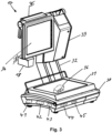
- FIG. 3 shows a shop scale 17, which is used in a sales facility 10.
- a sales facility 10 includes one or more shop scales 17.
- the shop scale 17 includes a first input/output unit 34, which faces the operator of the scale.
- the first input/output unit 34 is designed as a touchscreen.
- the shop scale 17 optionally also has a second output unit 35, which faces the customer and contains customer information displays.
- the person skilled in the art knows shop scales with a second output unit 35, the customer information also being displayed on the front cover 12 and the second output unit 35 of the shop scales 17 is therefore not absolutely necessary.
- the shop scale 17 has a load plate 31 which is connected to a weighing device 36 with which the weight of a product resting on the load plate 31 is determined.
- the shop scale 17 has a network unit that enables the shop scale 17 to be connected to the sales facility 10, to a network or to other devices.
- the connection is wired or wireless.
- the shop scale 17 optionally includes a printer 33 for printing receipts.
- Printer 33, first input/output unit 34 and second output unit 35 are connected to the body 30 of the shop scale 17 with a tripod 32.
- the projector 18 is integrated on or in the shop scale 17, for example by being attached to the screen, integrated in the tripod 32 or supported by the tripod 32, or integrated in the body 30 of the shop scale 17.
- the shop scale 17 comprises a control device 41, an evaluation device 42, an information unit 43, a first memory 44 and a second memory 45, the function of which will be discussed below.
- control device 41, evaluation device 42, information unit 43, first memory 44 and second memory 45 are mounted in the sales device 10, for example in the counter.
- the sales device 10 comprises a plurality of shop scales 17, all of which include a control device 41, an evaluation device 42, an information unit 43, a first memory 44 and a second memory 45.
- the sales facility 10 includes several shop scales 17, of which only includes a control device 41, an evaluation device 42, an information unit 43, a first memory 44 and a second memory 45.
- FIG 4 shows schematically a sales device 10 according to a first embodiment.
- the mat 14, which forms the floor of the display area 13, includes pressure sensors 15 which are arranged in a regular grid.
- the pressure sensors 15 locally measure a pressure that is triggered by a weight force and send a signal that is proportional to this weight force to an evaluation device 40 of the mat 14.
- the evaluation device 40 of the mat 14 consolidates the data from the pressure sensors 15 and gives a weight force, or a signal proportional to the weight, and an associated location on the mat 14 to a control device 41 of the sales device 10 and an evaluation device 42 of the sales device 10. Both the evaluation device 42 and the control device 41 of the sales device 10 are connected to a first memory 44.
- a connection between the location on the mat 14 and a product identification number is stored in the first memory 44.
- the evaluation device 42 can assign a product identification number to a location on the mat 14 using the data material stored in the first memory 44.
- product identification numbers are assigned to locations on the mat 14 based on operator input using the control device 41 of the sales device 10 and stored in memory 44.
- the operating input is made using the first input/output unit 34 of the shop scale 17, a computer or a tablet 46, which has appropriate software and can be electrically connected to the control device 41 of the sales device 10, for example via a wireless or wired connection.
- the evaluation device 42 passes on the determined product identification number to an information unit 43, which, based on the product identification number, receives information about the recognized product from a second memory for additional information Retrieves product.
- the information unit 43 processes this information accordingly, if necessary links it with a weight value and passes this information on to the projector 18, which makes it visible on the front cover 12.
- the information unit 43 provides the information to the second output unit 35 of the shop scale 17, on which this information is made visible.
- the information is partially visible on the second output unit 35 and partially on the front cover.
- the schematic representation of Figure 4 shows analogously to Figures 1 and 2 a system with a shop scale, a preferred embodiment of the invention including sales devices 10 which include a plurality of shop scales 17.
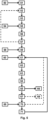
- FIG. 5 schematically shows a method for operating a sales facility 10.
- Steps 50 to 57 essentially concern the assignment of locations on the mat 14, which forms the display area 13, to corresponding product identification numbers of the products that are laid out at these locations on the mat 14 .
- This information is stored in the first memory 44.
- This is a training process of the sales device 10.
- Steps 60 to 71 of the method represent a sales process using a sales device 10.
- step 50 the sales facility is put into a filling mode by an operator input.
- the filling mode the operator places the products on the mat 14 in the display area 13 of the sales facility 10. This is, so to speak, a matter of clearing the counter.
- the sales facility 10 switches to filling mode in step 51.
- step 52 the pressure sensors 15 of the mat 14 sense a change because the operator has placed a product at a specific location on the mat 14.
- step 53 the evaluation device 40 of the mat 14 determines the location on the mat 14 at which the pressure change, that is to say the weight change, took place has.
- step 54 the operator enters a product identification number that identifies the product that has just been placed in the display area 13.
- the sales facility 10 receives the product identification number in step 55 and links it to the location where the product was stored in step 56. In step 57, this link is stored in the first memory 44 of the sales facility 10. If another product is placed on the mat 14, steps 52 to 57 are carried out accordingly. If the counter is completely filled, the operator enters corresponding information into the sales device 10 in step 58. The input by the operator in steps 50, 54 and 58 takes place via the first input/output unit 34 of the shop scale 17 or via a tablet 46 or a computer.
- the information is constantly transmitted to the sales facility 10, for example via a wireless network connection, or it is stored in the tablet 46 or the computer during the filling process of the counter and into the sales facility after the filling process 10 or loaded into the shop scales 17.
- the sales mode is started in the sales facility 10 in step 59. If the operator starts a new sales transaction in step 60, the procedure in step 61 waits for the entry of a new product.
- the new product is automatically entered into the store scales using the following process steps.
- step 62 a change in the signal from the pressure sensors 15 is perceived and in step 63, the location of the change in the signal from the pressure sensors 15 is determined using the evaluation unit 40 of the mat 14 and with the evaluation unit 42 of the sales device 10 and the data in the first memory 44 the corresponding product identification number is determined.
- the product is automatically loaded into the shop scale 17, so to speak placed on the shop scale 17.
- Step 65 corresponding additional information about the product identification number, that is, about the product removed from the counter, is read from the second memory 45 and this information is sent to the customer using the information unit 43, projector 18 and the front cover 12 and / or the second output unit 35 made visible in step 66.
- step 67 the weight of the product on the scale is determined using the weighing device 36 and displayed to the customer on the front cover 12 using the projector 18 or on the second output unit 35 of the shop scale 37 in step 68.
- weight and possibly also a price associated with the weight are displayed to the customer on the front cover 12 using the projector 18, in one embodiment it is provided that price and weight information are displayed on a white field on the front cover 12, so that this information is more visible because it is not in the transparent area of the front cover 12.
- Additional information about the corresponding products is displayed in the transparent area of the front cover 12. In one embodiment, this additional information is displayed in the area of the front cover 12 that the customer looks through when looking at the product in the display. This means that when the customer looks at the product in the display, they automatically see the associated additional information in their field of vision. Additional information about a product includes, for example, recipes, nutritional information, freshness information, information about origin, producer information, special offers, etc.
- step 70 If another product is to be added to the sales process in step 70, the process jumps back to step 61, in which a new product is removed the display area 13 is serviced. If the sales process is to be completed, this is confirmed by the operator in step 69 and the sales process then ends in step 71 with the printing of the receipt for the purchase. The operator can then start a new sales process in step 60. The operator's input in step 60 takes place via the first input/output unit 34 of the shop scale 17.
- Figure 6 shows schematically a sales device 10 according to a second embodiment.
- the determination of a location where a product was removed or added is not as in Figure 4 realized via a weight mat, but rather by determining the center of gravity.
- the sales device 10 includes a product presentation plate 60 that can be attached to the display area 13.
- the product presentation plate 60 is suitable for holding products to be sold and is a rigid plate. It can be removed from the display area 13 for cleaning purposes.
- the product presentation plate 60 is held floating by four load cells 61, 62, 63, 64.
- the load cells 61, 62, 63, 64 support the product presentation plate 60 at their corners or near the corners with their force introduction sides.
- the load cells 61, 62, 63, 64 independently determine an effective weight force that is created by the product presentation plate 60 and the products placed on it. A single weight force acts on each load cell 61, 62, 63, 64 in proportion to the total weight.
- the data from the load cells 61, 62, 63, 64 are transmitted to an evaluation unit 65.
- the evaluation unit determines center of gravity coordinates on the product presentation plate from the individual weight data from the load cells 61, 62, 63, 64.
- the coordinates on the product presentation plate begin in a corner near the load cell 63 with the coordinates (0, 0) and extend in the horizontal direction X and in the vertical direction Y.
- the load cells 61, 62, 63, 64 are shown as in Figure 6 shown assigned the corresponding weight data W61, W62, W63, W64.
- the formation of the center of gravity in the X direction is determined as follows: W61 + W62 / W61 + W62 + W63 + W64
- the formation of the center of gravity in the Y direction is determined as follows: W61 + W64 / W61 + W62 + W63 + W64
- coordinates on the product presentation plate 60 can be determined which correspond to the center of gravity coordinates of the product presentation plate. These coordinates are determined in the evaluation unit 65 based on the data from the load cells 61, 62, 63, 64 and passed on to the control device 41 and the evaluation device 42.
- FIG 7 schematically shows a method for determining a location on the product presentation plate 60 where a product was added or removed.
- This method of determining a location offers an alternative to steps 52 and 53 and to steps 62 and 63 if the sales device 10 does not include a mat 14 but a product presentation plate 60.
- step 71 all load cells 61, 62, 63, 64 are tared, that is, the product presentation plate 60 and all products applied thereto are treated as if they were a preload for the load cells 61, 62, 63, 64 and set to zero.
- a new weight value is measured by at least one load cell 61, 62, 63, 64 and received by the evaluation device 65.
- step 73 the evaluation device 65 calculates center of gravity coordinates based on the current weight data of the load cells 61, 62, 63, 64. These center of gravity coordinates do not reflect the center of gravity of the Product presentation plate 60 again, but rather the center of gravity of the weight change in the coordinate system of the product presentation plate. This is the place where a product was removed from the product presentation plate or placed. In step 74, this location is passed on to the control device 41 and/or the evaluation device 42.
- Figure 8 schematically shows a method for determining a location on the product presentation plate 60 where a product was added or removed.
- This method of determining a location offers an alternative to steps 52 and 53 and to steps 62 and 63 if the sales device 10 does not include a mat 14 but a product presentation plate 60.
- step 81 center of gravity coordinates of the current center of gravity of the product presentation plate 60, including all products placed on it, are determined. This is the real focus. The product presentation plate or at least the products placed on it are not tared.
- a new weight value is measured by at least one load cell 61, 62, 63, 64 and received by the evaluation device 65.
- step 83 new center of gravity coordinates are determined by the evaluation device 65 from the new data from the load cells 61, 62, 63, 64.
- step 84 a vector is formed from the previous center of gravity coordinates and the new shear point coordinates, which reflects the shift in the center of gravity coordinates. Starting from the previous centroid, if not scaled, the vector leads to the new centroid.
- step 85 the vector is scaled in inverse proportion using the total weight of the product presentation plate 60 and the products placed on it.
- the location at which a product was removed from or placed on the product presentation plate 60 is determined in step 86 by adding the scaled vector to the previous center of gravity coordinates. In step 87 this becomes Location passed on to the control device 41 and / or the evaluation device 42.
- DSP digital signal processor
- ASIC application specific integrated circuit
- FPGA field programmable gate array
- ROM read only memory
- RAM random access memory
- non-volatile memory is provided.
Landscapes
- Physics & Mathematics (AREA)
- Engineering & Computer Science (AREA)
- Mathematical Physics (AREA)
- Theoretical Computer Science (AREA)
- General Physics & Mathematics (AREA)
- Cash Registers Or Receiving Machines (AREA)
- Control Of Vending Devices And Auxiliary Devices For Vending Devices (AREA)
- Management, Administration, Business Operations System, And Electronic Commerce (AREA)
Description
- Die vorliegende Erfindung betrifft eine Verkaufseinrichtung zum Bedienverkauf. Mit der Verkaufseinrichtung werden zum Beispiel in Supermärkten oder in Fachgeschäften Fleisch, Wurst und Käse verkauft. Die Erfindung betrifft ferner ein Verfahren zum Betrieb einer Verkaufseinrichtung.
- Die
DE 10 2011 014 839 A1 zeigt eine Verkaufstheke mit einem Wägesystem, das eine Positionserkennungseinrichtung umfasst, die mittels Lichtgitter die Position eines zu entnehmenden Lebensmittels erkennt und daraus auf das Lebensmittel rückschließt. - Die
DE 100 45 516 A1 zeigt eine Verkaufstheke für Eis, wobei der Zugriff in einen bestimmten Eisbehälter mittels Lichtschranken ermittelt wird und daraus wird auf die Anzahl verkaufter Eiskugeln pro Sorte zurückgeschlossen. Ebenfalls sind für jeden Eisbehälter Gewichtssensoren vorgesehen, die die Gesamtmasse des Eisbehälters bestimmen. - Aufgabe der Erfindung ist es eine Verkaufseinrichtung zu schaffen, die den Verkaufsvorgang in einem Ladengeschäft effizienter gestaltet, für den Bediener vereinfacht und dem Kunden auf seinen Einkauf zugeschnittene Zusatzinformationen zur Verfügung stellt.
- Diese Aufgabe wird durch eine Verkaufseinrichtung nach Anspruch 1 und ein Verfahren zum Betrieb einer Verkaufseinrichtung nach Anspruch 15 gelöst.
- Erfindungsgemäß wird eine Verkaufseinrichtung zum Bedienverkauf vorgeschlagen. An einer Verkaufstheke werden in einem Supermarkt oder Fachgeschäft insbesondere Fleisch, Wurst oder Käse im Frischeverkauf verkauft. Das heißt, die Produkte werden anhand des Kundenwunsches verwogen und abgepackt. Dabei werden auch Produkte nach Stückpreis, zum Beispiel Dosen oder nach Festgewicht ausgezeichnete Lebensmittel verkauft. Die Verkaufseinrichtung besteht aus mindestens einer Ladenwaage und einer Theke. Die Theke umfasst einen Auslagebereich, ein Thekenbrett und eine Abdeckung. Die Abdeckung der Theke ist in einer Ausführungsform transparent und besteht aus einem vorderen Teil, einem oberen Teil und seitlichen Teilen. Drucksensoren sind im Auslagebereich der Verkaufseinrichtung angebracht, die lokal eine jeweilige Gewichtskraft erfassen. Die Verkaufseinrichtung umfasst eine Auswerteeinheit. In einer Ausführungsform ist die Auswerteeinheit in mindestens einer der Ladenwaagen angebracht. Die Auswerteeinheit ermittelt bei einer Veränderung eines Signals mindestens eines Drucksensors den Ort, der dem Signal entspricht. So kann ein Ort innerhalb des Auslagebereichs ermittelt werden, an dem sich die Gewichtskraft auf die Drucksensoren ändert. Anhand dieser Position ist ermittelbar, um welches Produkt es sich handelt. In einer Ausführungsform ermittelt ein Drucksensor permanent oder periodisch den Druck, das heißt einen Gewichtswert oder einen Wert proportional zum Gewichtswert, der auf dem Drucksensor lastet. Eine Veränderung des vom Drucksensor festgestellten Gewichts, das zu einer Veränderung des Signals eines Drucksensors führt, wird ausgelöst durch das Entnehmen von Produkten, zum Beispiel im Falle von geschnittener und aufgestapelter Wurst durch das Entnehmen eines Teil des Stapels. Eine Veränderung des vom Drucksensor festgestellten Gewichts, das zu einer Veränderung des Signals eines Drucksensors führt, wird auch ausgelöst durch das Drücken auf das Produkt zum Beispiel mit einer Gabel. Eine Bedienperson kann auf das Produkt drücken, um das Signal auszulösen und so das Produkt durch die Verkaufseinrichtung identifizieren zu lassen. Die erfindungsgemäße Verkaufseinrichtung erleichtert die Bedienung und die Auswahl von Produkten. Anstatt wie im Stand der Technik eine Produkterkennungsnummer (PLU Nummer) in einem Bedienfeld einer Ladenwaage einzugeben, um ein Produkt zu identifizieren, ist es mit der erfindungsgemäßen Verkaufseinrichtung ausreichend, wenn ein Bediener auf das Produkt drückt oder das Produkt entnimmt. Mit diesem Vorgang wird das Produkt automatisch ausgewählt.
- Erfindungsgemäß umfasst die Ladenwaage eine Wägeeinheit, die eine Gewichtsinformation generiert. Die Verkaufseinrichtung, insbesondere die Ladenwaage umfasst eine Informationseinheit, die entsprechende Zusatzinformationen zu einem Produkt generiert. Ein dem Kunden zugewandtes Display der Verkaufseinrichtung und/oder der Ladenwaage zeigt diese Zusatzinformationen und/oder Gewichtsinformation an.
- In einer Ausführungsform sind die Drucksensoren mindestens drei Wägezellen, vorzugsweise vier Wägezellen. Bei vier Wägezellen sind die Wägezellen mit ihren Krafteinleitungsseiten an den vier Ecken einer Produktpräsentationsplatte befestigt. Die Produktpräsentationsplatte bildet den Boden des Auslagebereichs. Auf ihr liegen die zu verkaufenden Produkte. Bei drei Wägezellen befinden sich die Wägezellen in drei Ecken der Produktpräsentationsplatte und die vierte Ecke ist an einem Fixpunkt gelagert. Die Auswerteeinheit erhält die Wägedaten aus den Wägezellen und ermittelt daraus die Schwerpunktkoordinaten der Produktpräsentationsplatte. Die Produktpräsentationsplatte hat ein Eigengewicht sowie das Gewicht der Produkte, die auf ihr gelagert sind. Die komplette Produktpräsentationsplatte hat einen Schwerpunkt, der von beiden Gewichtsanteilen abhängt.
- In einer Ausführungsform ermittelt die Auswerteeinheit in periodischen Abständen oder bei einer Änderung des Gesamtgewichts der Produktpräsentationsplatte aus den Wägedaten der Wägezellen neue Schwerpunktdaten. Um eine Änderung des Gesamtgewichts der Produktpräsentationsplatte festzustellen, ist es ausreichend, wenn eine Änderung der auf eine Wägezelle einwirkenden Gewichtskraft detektiert wird.
- In einer Ausführungsform werden alle Wägezellen periodisch tariert, das heißt periodisch auf Null gesetzt. Periodisch in diesem Zusammenhang meint regelmäßig mit kurzen Zeitabständen. Wenn sich jedoch die Gewichtskraft auf einer Wägezelle gerade ändert, dann darf kein Tarierungsvorgang stattfinden. Insofern meint periodisch nicht, nach einem starren Zeitschema, das nicht unterbrochen werden kann. Vielmehr ist damit gemeint, regelmäßig wenn die Wägezellen gerade keine Veränderung des Gesamtgewichts auf der Produktpräsentationsplatte detektieren. Durch das Tarieren der Wägezellen sind die von den Wägezellen an die Auswerteeinheit übermittelten Gewichtsdaten bei allen Wägezellen Null, solange kein Produkt auf die Produktpräsentationsplatte gelegt wird oder von ihr entfernt wird. Bei einer Änderung des Gesamtgewichts der Produktpräsentationsplatte, das heißt wenn ein Produkt auf die Produktpräsentationsplatte gelegt wird oder von ihr entnommen wird, werden die Wägedaten mindestens einer Wägezelle ungleich Null sein. In diesem Fall ermittelt die Auswerteeinheit aus den neuen Wägedaten der Wägezellen neue Schwerpunktkoordinaten. Diese neuen Schwerpunktkoordinaten entsprechen dem Ort auf der Produktpräsentationsplatte, an dem das Produkt entnommen oder hinzugefügt wurde. Dieser Ort ist der von der Auswerteeinheit zugeordnete Ort innerhalb des Auslagebereichs.
- In einer Ausführungsform empfängt die Auswerteeinheit Wägedaten von den Wägezellen, die das jeweils anteilige Gewicht der Produktpräsentationsplatte mit all den darauf liegenden Produkten wiederspiegeln. Bei einer Änderung der Wägedaten oder in periodischen Abständen bildet die Auswerteeinheit einen Vektor, der die Veränderung zwischen den vorhergehenden Schwerpunktkoordinaten und den neuen Schwerpunktkoordinaten wiedergibt. Der von der Auswerteeinheit zugeordnete Ort auf der Produktpräsentationsplatte entspricht dem vorhergehenden Schwerpunkt verschoben entlang des Vektors, wobei die Länge der Verschiebung mit dem Gesamtgewicht der Produktproduktionsplatte skaliert ist.
- In einer Ausführungsform sind die Drucksensoren in einer Matte eingearbeitet. Die Matte dient als Boden des Auslagebereichs auf dem die Produkte ausgelegt sind. Die Matte bildet flächig oder in einem regelmäßigem Raster Gewichtswerte.
- In einer Ausführungsform ist das Material aus dem die Matte gebildet ist hygienisch und lebensmittelecht. So wird sichergestellt, dass die Matte gut gereinigt werden kann und Lebensmittel direkt und unverpackt auf der Matte abgelegt werden können. Die Matte bildet mittels eines kapazitiven oder resistiven Messverfahrens die Gewichtswerte.
- In einer Ausführungsform ist das Raster der Drucksensoren derart ausgestaltet, dass mittels der Kombination der Signale der Drucksensoren die Umrisse der Produkte im Auslagebereich ermittelbar sind. Eine Steuereinheit in der Verkaufseinrichtung, zum Beispiel ein Teil der Auswerteeinheit, verknüpft die Signale der Drucksensoren derart, dass aus der Kombination der einzelnen Signale und der Kenntnis der Lage der einzelnen Sensoren im Auslagebereich die Umrisse der Produkte zumindest approximiert werden können.
- In einer Ausführungsform umfasst die Auswerteeinheit eine erste Speichereinheit. Die erste Speichereinheit ordnet entsprechende Produkterkennungsnummern den Orten im Auslagebereich zu. Ist eine Veränderung eines Signals eines oder mehrerer Drucksensoren eingegangen, kann so auf einen Ort im Auslagebereich rückgeschlossen werden, wobei eine Produkterkennungsnummer die zu diesem Ort beziehungsweise zu diesem Drucksensor oder diesen Drucksensoren gehört identifiziert wird. In einer Ausführungsform ist für den Fall, dass die Signale der Drucksensoren nicht eindeutig einer Produkterkennungsnummer zugeordnet werden können, vorgesehen, dass eine geringe Zahl von Produkterkennungsnummern identifiziert werden, die bei einer entsprechenden Änderung des Signals der Drucksensoren in Frage kommen. Diese werden der Bedienperson zur Auswahl angezeigt.
- Erfindungsgemäß ist das dem Kunden zugewandte Display der Verkaufseinrichtung in einer vorderen Abdeckung der Theke integriert. Die vordere Abdeckung weist einen transparenten Bereich auf und die Zusatzinformationen werden zumindest teilweise in dem transparenten Bereich der vorderen Abdeckung angezeigt. Ein Kunde, der durch den transparenten Bereich auf den Auslagebereich der Theke schaut, sieht die Produkte im Auslagebereich und dazu in unmittelbarer Nähe in seinem Blickfeld die entsprechenden Zusatzinformationen, Gewichtsinformationen und/oder Preisinformationen, die durch die Verkaufseinrichtung angezeigt werden.
- In einer Ausführungsform weist die vordere Abdeckung einen transparenten und einen nicht transparenten Bereich auf. Preisinformation und/oder Gewichtsinformation werden in dem nicht transparenten Bereich der vorderen Abdeckung angezeigt. Zusatzinformationen werden in dem transparenten Bereich der vorderen Abdeckung angezeigt.
- In einer Ausführungsform umfasst die Verkaufseinrichtung einen Projektor, der im Bereich einer oberen Abdeckung angebracht ist. Der Projektor projiziert ein Lichtsignal auf die vordere Abdeckung. Die vordere Abdeckung dient als Projektionsfläche für das Lichtsignal. Das Lichtsignal ist auf der Seite der vorderen Abdeckung sichtbar, auf der das Lichtsignal nicht auf die vordere Abdeckung trifft. Mit anderen Worten hat die vordere Abdeckung eine Vorderseite und eine Rückseite. Die Vorderseite ist dem Kunden zugewandt, die Rückseite ist dem Auslagebereich zugewandt. Der Projektor ist derart angeordnet, dass das Lichtsignal auf die Rückseite der vorderen Abdeckung trifft. Das projizierte Lichtsignal ist auf der Vorderseite der vorderen Abdeckung sichtbar, so dass der Kunde die Information des Lichtsignals auf der vorderen Abdeckung sehen kann. Die Preisinformation und/oder Gewichtsinformation werden ebenfalls auf die Rückseite der vorderen Abdeckung projiziert, jedoch in einen Bereich der vorderen Abdeckung der nicht transparent oder semi-transparent ist. Zum Beispiel ist das ein Bereich, der von der Kundenseite aus weiß wirkt. Dennoch ist das Lichtsignal, das auf die Rückseite der vorderen Abdeckung in diesen Bereich trifft, auf der Vorderseite sichtbar. So können Preisinformation und/oder Gewichtsinformation auf einem weißen Untergrund dargestellt werden, so dass sie einfacher zu lesen sind.
- In einer Ausführungsform weist die vordere Abdeckung eine holographische Struktur auf. Die holographische Struktur macht Licht, das in einem ersten Winkelbereich auf die vordere Abdeckung trifft, sichtbar. Für Licht, das in einem zweiten Winkelbereich auf die vordere Abdeckung trifft, ist die holographische Struktur transparent.
- In einer Ausführungsform ist der Projektor in einem Bereich von Streben untergebracht, die die Begrenzung der Abdeckung bilden. So ist der Projektor wenig störend untergebracht und liegt nicht im Blickfeld von Kunden oder Bedienpersonen.
- In einer Ausführungsform ist der Projektor als Teil der Ladenwaage ausgebildet oder mit der Ladenwaage fest verbunden. In einer Ausführungsform ist der Projektor im Gehäuse der Ladenwaage angebracht und das Gehäuse der Ladenwaage hat eine optische Öffnung, zum Beispiel eine Linse. In einer Ausführungsform ist der Projektor anstelle des Kundendisplays angebracht. In einer Ausführungsform ist der Projektor in einem Stativ der Ladenwaage angebracht, das Bedienerdisplay und/oder Kundendisplay haltert.
- In einer Ausführungsform ist der Projektor in der Verkaufseinrichtung derart angeordnet, dass sein Lichtsignal in einem ersten Winkelbereich auf die vordere Abdeckung trifft. Ein Lichtsignal das in dem ersten Winkelbereich auf die vordere Abdeckung trifft, also in einem bestimmten Winkel auf die Rückseite der vorderen Abdeckung trifft, ist durch die holographische Struktur der vorderen Abdeckung auf der vorderen Abdeckung sichtbar.
- In einer Ausführungsform umfasst die Verkaufseinrichtung eine Steuereinheit. Die Steuereinheit empfängt in einem Befüllungsmodus ein Signal mindestens eines Drucksensors, das eine Veränderung des Gewichtswertes an einem Ort des Auslabgebereichs wiedergibt. Die Steuereinheit empfängt in einem Befüllungsmodus von einer Ein/Ausgabeeinheit eine Produkterkennungsnummer, die dem Produkt entspricht, das an dem Ort abgelegt ist. Die Steuereinheit verknüpft die Produkterkennungsnummer mit dem Ort und hinterlegt diese Verknüpfung in der ersten Speichereinheit. Auf diese Weise kann beim Befüllen des Auslagebereichs mit verschiedenen Produkten die Verkaufseinrichtung angelernt werden, sodass die Verknüpfung zwischen Ort und Produkt in der ersten Speichereinheit abgelegt wird. Auf diese Information wird später beim Verkaufsvorgang zurückgegriffen.
- In einer Ausführungsform ist die Ein/Ausgabeeinheit ein Bedienerdisplay einer Ladenwaage. In einer Ausführungsform ist die Ein/Ausgabeeinheit ein Tablet, das mit der Verkaufseinheit elektrisch verbindbar ist.
- In einer Ausführungsform umfasst die Verkaufseinrichtung mehrere Ladenwaagen, die jeweils die Funktion der Ladenwaage übernehmen. Die Ladenwaagen sind über ein Netzwerk miteinander verbunden, sodass nach dem Befüllen des Auslagebereichs und der entsprechenden Speicherung der Verknüpfung zwischen Produkterkennungsnummer und Ort in dem ersten Speicherbereich einer Ladenwaage diese Information von der einen Ladenwaage zu den anderen Ladenwaagen weitergeleitet wird.
- Erfindungsgemäß wird ein Verfahren zum Betrieb einer Verkaufseinrichtung zum Bedienverkauf von insbesondere Fleisch, Wurst oder Käse vorgeschlagen. Die Verkaufseinrichtung, mit der das Verfahren ausgeführt wird, umfasst einen Auslagebereich mit Drucksensoren, die eine jeweilige Gewichtskraft erfassen. Darunter ist zu verstehen, dass die Drucksensoren ein Signal erzeugen, dass der Kraft entspricht, die auf den Drucksensoren lastet. Das ausgegebene Signal entspricht der Gewichtskraft oder ist proportional zur Gewichtskraft. Die Verkaufseinrichtung umfasst eine Auswerteeinrichtung, die elektrisch mit den Drucksensoren verbunden ist. Das Verfahren umfasst einen Schritt des Empfangens eines Signals von mindestens einem Drucksensor, das eine Veränderung des Gewichtswertes, also der Gewichtskraft, an einem Ort im Auslagebereich wiedergibt. Das Verfahren umfasst den Schritt des Ermittelns einer Produkterkennungsnummer, die in einer ersten Speichereinheit mit dem Ort verknüpft ist, der dem Signal entspricht. Diese Produkterkennungsnummer wird automatisch in einer Ladenwaage ausgewählt, das heißt, die Ladenwaage schaltet automatisch das entsprechende Produkt, das zu der Produkterkennungsnummer gehört, aktiv. Die zur Produkterkennungsnummer zugehörigen Informationen werden aus einer zweiten Speichereinheit der Ladenwaage gelesen. Dies hat den Vorteil, dass das händische Eingeben der Produkterkennungsnummer über das Bediendisplay ersetzt wird.
- Erfindungsgemäß umfasst das Verfahren den Schritt des Anzeigens mindestens einer der Produkterkennungsnummer zugehörigen Information und/oder Preis und/oder Gewichtsinformation auf einer vorderen Abdeckung einer Theke. Die Theke ist Teil der Verkaufseinrichtung und umfasst den Auslagebereich.
- In einer Ausführungsform umfasst das Verfahren den Schritt des Empfangens eines Signals von mindestens drei, vorzugsweise vier Wägezellen. Die Signale entsprechen den Gewichtskräften an den Ecken einer Produktpräsentationsplatte. Des Weiteren umfasst das Verfahren den Schritt des Ermittelns mit einer Auswerteeinheit von Schwerpunktkoordinaten aus den empfangenen Signalen. Außerdem umfasst das Verfahren den Schritt das Empfangens eines Signals das einer neuen Gewichtskraft entspricht von mindestens einer Wägezelle und des Ermittelns mit der Auswerteeinheit neuer Schwerpunktkoordinaten aus den von den Wägezellen aktuell empfangenen Daten.
- In einer Ausführungsform umfasst das Verfahren weiter den Schritt des periodischen Tarierens aller Wägezellen. Bei einer Änderung des von mindestens einer Wägezelle gemessenen Gewichts ermittelt das Verfahren neue Schwerpunktkoordinaten aus den dann neu empfangenen neuen Wägedaten. Das Verfahren ordnet einen Ort auf der Produktpräsentationsplatte zu, wobei der Ort den neuen Schwerpunktkoordinaten entspricht. Dieser Ort ist der Ort, an dem ein Produkt auf der Produktpräsentationsplatte entnommen oder hinzugefügt wurde.
- In einer Ausführungsform umfasst das Verfahren bei einer Änderung des von mindestens einer Wägezelle gemessenen Gewichts den Schritt des Ermittelns von neuen Schwerpunktkoordinaten mit neu empfangenen Wägedaten. Des Weiteren ermittelt das Verfahren einen Vektor zwischen den vorhergehenden Schwerpunktkoordinaten und den neuen Schwerpunktkoordinaten. Mit Hilfe dieses Vektors wird ausgehend von den vorhergehenden Schwerpunktkoordinaten und unter Berücksichtigung bzw. Skalierung des Vektors mittels des Gesamtgewichts der Produktpräsentationsplatte ein Ort auf der Produktpräsentationsplatte zugeordnet, der dem Ort entspricht, an dem etwas von der Produktpräsentationsplatte entnommen oder hinzugefügt wurde.
- Erfindungsgemäß ist die zur Produkterkennungsnummer zugehörige Information mindestens eine von Preis pro Gewicht, Preis pro Stück, Produktname, Inhaltsstoffe, Allergene, Sonderangebote, Kochrezepte und zu dem Produkt passende Waren.
- In einer Ausführungsform umfasst das Verfahren einen weiteren Schritt zur Ermittlung einer Gewichtsinformation in der Ladenwaage und zur Berechnung eines Preises aus der der Produkterkennungsnummer zugehörigen Information. Dabei ist die der Produkterkennungsnummer zugehörige Information zum Beispiel ein Preis pro Gewicht.
- In einer Ausführungsform umfasst das Verfahren den Schritt des Empfangens eines Signals von einer Ein/Ausgabeeinheit, welches die Verkaufseinrichtung in einen Befüllungsmodus verbringt. Im Befüllungsmodus wird im nächsten Schritt ein Signal mindestens eines Drucksensors empfangen. Das Signal gibt eine Veränderung des Gewichtswertes an einem Ort des Auslabgebereichs wieder. In einem nächsten Schritt wird eine Produkterkennungsnummer über die Ein/Ausgabeeinheit empfangen, wobei die Produkterkennungsnummer dem Produkt entspricht, das an dem Ort abgelegt wurde. Die Produkterkennungsnummer wird im nächsten Schritt mit dem Ort verknüpft und diese Information wird in der ersten Speichereinheit abgelegt.
- In einer Ausführungsform ist die Ein/Ausgabeeinheit ein Bedienerdisplay einer Ladenwaage. In einer Ausführungsform ist die Ein/Ausgabeeinheit ein Tablet, das mit der Verkaufseinrichtung elektrisch verbindbar ist.
- In einer Ausführungsform werden die Signale aller Drucksensoren periodisch ausgewertet. Für jedes Produkt im Auslagebereich wird ein Gewichtswert gebildet. Um den Gewichtswert für ein Produkt zu bilden wird je nach Lage der Drucksensoren und Befüllung des Auslagebereichs das Signal eines oder mehrere Drucksensoren herangezogen. Ein Bestandssignal wird auf einer Ein/Ausgabeeinheit ausgegeben, falls der Gewichtswert für ein Produkt eine untere Schranke unterschreitet. Das Bestandssignal weist den Nutzer darauf hin, dass der Vorrat des Produktes eine definierte Grenze unterschreitet und zeitnah nachgefüllt werden muss.
- In einer Ausführungsform wird das Bestandssignal an einen Produktionsbereich gesendet, zum Beispiel an eine Schneidemaschine oder in einen Produktvorbereitungsraum, wo eine gewisse Menge des Produktes zum Auffüllen vorbereitet und bereitgestellt wird.
- Einige Ausführungsformen der Erfindung sind in den Zeichnungen beispielhaft gezeigt und nachfolgend beschrieben. Es zeigen, jeweils in schematischer Darstellung:
- Fig. 1
- eine erfindungsgemäße Verkaufseinrichtung von der Kundenseite,
- Fig. 2
- eine erfindungsgemäße Verkaufseinrichtung von der Bedienerseite,
- Fig. 3
- eine Ladenwaage als Teil der Verkaufseinrichtung,
- Fig. 4
- ein Blockdiagramm einer Verkaufseinrichtung nach einer ersten Ausführungsform,
- Fig. 5
- ein Verfahren zum Betrieb einer Verkaufseinrichtung,
- Fig. 6
- ein Blockdiagramm einer Verkaufseinrichtung nach einer zweiten Ausführungsform,
- Fig. 7
- ein erstes Verfahren zur Bestimmung eines Ortes, an dem ein Produkt entnommen oder abgelegt wurde, und
- Fig. 8
- ein zweites Verfahren zur Bestimmung eines Ortes, an dem ein Produkt entnommen oder abgelegt wurde.
-
Figur 1 zeigt eine erfindungsgemäße Verkaufseinrichtung 10 von einer Kundenseite.Figur 2 zeigt eine erfindungsgemäße Verkaufseinrichtung 10 von einer Bedienerseite. Die Verkaufseinrichtung 10 ist geeignet für den Bedienverkauf von insbesondere Fleisch, Wurst oder Käse, also zum Frischeverkauf. Die Verkaufseinrichtung 10 besteht aus einer Theke, die einen Auslagebereich 13 umfasst. Eine Abdeckung der Theke besteht aus seitlichen Abdeckungen 11b, einer oberen Abdeckung 11a und einer vorderen Abdeckung 12, die den Auslagebereich 13 auf der Kundenseite abschließen. Die Abdeckungen 11a, 11b, 12 sind aus transparentem Material, sodass man die Produkte im Auslagebereich 13 sehen kann. Auf der Bedienerseite ist der Auslagebereich 13 zugänglich. Die Theke besteht ferner aus einem Thekenbrett 16, auf dem eine oder mehrere Ladenwaagen 17 stehen. Der Boden des Auslagebereichs 13, auf dem die normalerweise unverpackten Produkte liegen, besteht aus einer Matte 14, in die mehrere Drucksensoren 15 in einem regelmäßigen Raster eingearbeitet sind. Die Drucksensoren 15 arbeiten zum Beispiel auf kapazitiver oder resistiver Basis, das heißt durch Messung einer Veränderung der Kapazität oder des elektrischen Widerstands. Die Matte 14 besteht aus hygienischem und lebensmittelechtem Material und ist leicht zu reinigen, sodass sie zur Auslage von Frischeprodukten geeignet ist. - Die vordere Abdeckung 12 ist aus Sicht des Kunden, also aus der Richtung vor der Verkaufseinrichtung 10 transparent. Trifft jedoch Licht in einem ersten Winkelbereich auf die vordere Abdeckung 12, zum Beispiel aus einem Winkelbereich wie er sich zwischen vorderer Abdeckung 12 und einem Projektor 18 ergibt, ist die vordere Abdeckung 12 für dieses Licht nicht transparent. Der Projektor 18 ist dabei an der Ladenwaage 17 angebracht, in der Ladenwaage 17 integriert oder in der Theke, vorzugsweise an einem unauffälligen Ort, angebracht. Die vordere Abdeckung 12 bildet Licht aus diesem ersten Winkelbereich, also Licht das aus Richtung des Projektors 18 auf die vordere Abdeckung 12 trifft, in einer Projektion ab. Dies wird zum Beispiel dadurch erreicht, dass in der vorderen Abdeckung 12 eine holographische Struktur eingearbeitet ist, die dazu führt, dass Licht, welches in dem ersten Winkelbereich auf die Rückseite der vorderen Abdeckung 12 fällt, auf der vorderen Seite der vorderen Abdeckung 12 sichtbar ist. In einer Ausführungsform besteht die vordere Abdeckung aus einem transparenten bildgebenden Material, und ist zum Beispiel als transparentes LCD oder OLED Display ausgeführt, das zugleich die vordere Abdeckung 12 bildet. In diesem Fall umfasst die Verkaufseinrichtung 10 keinen Projektor 18, jedoch eine Steuerung für das Display.
Figur 1 und 2 zeigen eine Verkaufseinrichtung 10, die eine Ladenwaage 17 umfasst. Die Erfindung schließt Verkaufseinrichtungen 10, die mehrere Ladenwaagen 17 umfassen, von denen jede selbstständig ein Bild für die vordere Abdeckung 12 generiert und gegebenenfalls auf die vordere Abdeckung 12 projiziert, mit ein. -
Figur 3 zeigt eine Ladenwaage 17, die in einer Verkaufseinrichtung 10 Anwendung findet. Eine Verkaufseinrichtung 10 umfasst eine oder mehrere Ladenwaagen 17. Die Ladenwaage 17 umfasst eine erste Ein/Ausgabeeinheit 34, die dem Bediener der Waage zugewandt ist. Die erste Ein/Ausgabeeinheit 34 ist als Touchscreen ausgeführt. Die Ladenwaage 17 weist optional ferner eine zweite Ausgabeeinheit 35 auf, die dem Kunden zugewandt ist und Kundeninformationen anzeigt. Der Fachmann kennt Ladenwaage mit einer zweiten Ausgabeeinheit 35, wobei die Kundeninformation auch auf der vorderen Abdeckung 12 angezeigt wird und die zweite Ausgabeeinheit 35 der Ladenwaage 17 deshalb nicht zwingend notwendig ist. Die Ladenwaage 17 weist eine Lastplatte 31 auf, die mit einer Wägevorrichtung 36 verbunden ist, mit derer das Gewicht eines Produkts, das auf der Lastplatte 31 aufliegt, bestimmt wird. Die Ladenwaage 17 weist eine Netzwerkeinheit auf, die die Anbindung der Ladenwaage 17 an die Verkaufseinrichtung 10, an ein Netzwerk oder an weitere Geräte ermöglicht. Die Anbindung ist dabei kabelgebunden oder kabellos. Die Ladenwaage 17 umfasst optional einen Drucker 33 zum Drucken von Belegen. Drucker 33, erste Ein/Ausgabeeinheit 34 und zweite Ausgabeeinheit 35 sind mit einem Stativ 32 mit dem Körper 30 der Ladenwaage 17 verbunden. In einer Ausführungsform ist der Projektor 18 an oder in der Ladenwaage 17 integriert, zum Beispiel indem er am Bildschirm angebracht ist, im Stativ 32 integriert ist oder vom Stativ 32 gehaltert wird oder im Körper 30 der Ladenwaage 17 integriert ist. In allen Fällen ist ein freies Sichtfeld der Linse des Projektors 18 auf die Rückseite der vorderen Abdeckung 12 vorhanden und es ist gewährleistet, dass das Licht des Projektors 18 in einem ersten Winkelbereich auf die vordere Abdeckung 12 trifft, sodass das Bild des Projektors 18 auf der vorderen Abdeckung 12 sichtbar ist. In einer Ausführungsform umfasst die Ladenwaage 17 eine Steuereinrichtung 41, eine Auswerteeinrichtung 42, eine Informationseinheit 43, einen ersten Speicher 44 und einen zweiten Speicher 45 auf deren Funktion im Folgenden eingegangen wird. In einer Ausführungsform sind Steuereinrichtung 41, Auswerteeinrichtung 42, Informationseinheit 43, erster Speicher 44 und zweiter Speicher 45 in der Verkaufseinrichtung 10, zum Beispiel in der Theke angebracht. In einer Ausführungsform umfasst die Verkaufseinrichtung 10 mehrere Ladenwaagen 17, von denen alle eine Steuereinrichtung 41, eine Auswerteeinrichtung 42, eine Informationseinheit 43, einen ersten Speicher 44 und einen zweiten Speicher 45 umfassen. In einer Ausführungsform umfasst die Verkaufseinrichtung 10 mehrere Ladenwaagen 17, von denen nur eine Steuereinrichtung 41, eine Auswerteeinrichtung 42, eine Informationseinheit 43, einen ersten Speicher 44 und einen zweiten Speicher 45 umfasst. -
Figur 4 zeigt schematisch eine Verkaufseinrichtung 10 nach einer ersten Ausführungsform. Die Matte 14, die den Boden des Auslagebereichs 13 bildet, umfasst Drucksensoren 15, die in einem regelmäßigen Raster angeordnet sind. Die Drucksensoren 15 messen lokal einen Druck, der durch eine Gewichtskraft ausgelöst wird und geben ein Signal, dass dieser Gewichtskraft proportional ist, an eine Auswerteeinrichtung 40 der Matte 14. Die Auswerteeinrichtung 40 der Matte 14 konsolidiert die Daten der Drucksensoren 15 und gibt eine Gewichtskraft, oder ein zur Gewichtskraft proportionales Signal, und einen damit verbundenen Ort auf der Matte 14 an eine Steuereinrichtung 41 der Verkaufseinrichtung 10 und eine Auswerteeinrichtung 42 der Verkaufseinrichtung 10 weiter. Sowohl die Auswerteeinrichtung 42 wie auch die Steuereinrichtung 41 der Verkaufseinrichtung 10 sind mit einem ersten Speicher 44 verbunden. Im ersten Speicher 44 ist ein Zusammenhang zwischen dem Ort auf der Matte 14 und einer Produkterkennungsnummer abgelegt. Das heißt, die Auswerteeinrichtung 42 kann mithilfe des im ersten Speicher 44 abgelegten Datenmaterials einem Ort auf der Matte 14 eine Produkterkennungsnummer zuordnen. In einem Einlernprozess werden mithilfe der Steuereinrichtung 41 der Verkaufseinrichtung 10 aufgrund von Bedienereingaben Produkterkennungsnummern zu Orten auf der Matte 14 zugeordnet und in Speicher 44 hinterlegt. Die Bedienungseingabe erfolgt mittels der ersten Ein/Ausgabeeinheit 34 der Ladenwaage 17, eines Computer oder eines Tablet 46, das eine entsprechende Software aufweist und elektrisch zum Beispiel über eine drahtlose oder drahtgebundene Verbindungen mit der Steuereinrichtung 41 der Verkaufseinrichtung 10 verbunden werden kann. - Die Auswerteeinrichtung 42 gibt die ermittelte Produkterkennungsnummer an eine Informationseinheit 43 weiter, die aufgrund der Produkterkennungsnummer aus einem zweiten Speicher für Zusatzinformationen Informationen zum erkannten Produkt abruft. Die Informationseinheit 43 arbeitet diese Informationen entsprechend auf, verknüpft sie gegebenenfalls mit einem Gewichtswert und gibt diese Informationen an den Projektor 18 weiter, der sie auf der vorderen Abdeckung 12 sichtbar macht. In einer Ausführungsform stellt die Informationseinheit 43 die Informationen der zweiten Ausgabeeinheit 35 der Ladenwaage 17 zur Verfügung, auf dem diese Informationen sichtbar gemacht werden. In einer Ausführungsform werden die Informationen teilweise auf der zweiten Ausgabeeinheit 35 und teilweise auf der vorderen Abdeckung sichtbar gemacht. Die schematische Darstellung von
Figur 4 zeigt analog zuFigur 1 und 2 ein System mit einer Ladenwaage, wobei eine bevorzugte Ausführungsform der Erfindung Verkaufseinrichtungen 10, die mehrere Ladenwaagen 17 umfassen, mit einschließt. -
Figur 5 zeigt schematisch ein Verfahren zum Betrieb einer Verkaufseinrichtung 10. Dabei betreffen die Schritte 50 bis 57 im Wesentlichen das Zuweisen von Orten auf der Matte 14, die den Auslagebereich 13 bildet, zu entsprechenden Produkterkennungsnummern der Produkte, die an diesen Orten auf der Matte 14 ausgelegt sind. Diese Information wird im ersten Speicher 44 gespeichert. Es handelt sich hierbei um einen Anlernprozess der Verkaufseinrichtung 10. Die Schritte 60 bis 71 des Verfahrens bilden einen Verkaufsvorgang mithilfe einer Verkaufseinrichtung 10 ab. - In Schritt 50 wird durch eine Bedienereingabe die Verkaufseinrichtung in einen Befüllungsmodus versetzt. Im Befüllungsmodus legt die Bedienperson die Produkte auf die Matte 14 im Auslagebereich 13 der Verkaufseinrichtung 10. Es handelt sich sozusagen um das Einräumen der Theke. Nach der Bedienereingabe wechselt die Verkaufseinrichtung 10 in Schritt 51 in den Befüllungsmodus. In Schritt 52 nehmen die Drucksensoren 15 der Matte 14 eine Veränderung wahr, da der Bediener ein Produkt an einen bestimmten Ort auf der Matte 14 gelegt hat. In Schritt 53 bestimmt die Auswerteeinrichtung 40 der Matte 14 den Ort auf der Matte 14, auf dem die Druckänderung, das heißt die Gewichtsänderung, stattgefunden hat. In Schritt 54 gibt die Bedienperson eine Produkterkennungsnummer ein, die das Produkt identifiziert, das gerade in den Auslagebereich 13 gelegt wurde. Die Verkaufseinrichtung 10 empfängt in Schritt 55 die Produkterkennungsnummer und verknüpft sie in Schritt 56 mit dem Ort, an dem das Produkt abgelegt wurde. In Schritt 57 wird diese Verknüpfung im ersten Speicher 44 der Verkaufseinrichtung 10 gespeichert. Wird ein weiteres Produkt auf die Matte 14 gelegt, so werden für dieses entsprechend die Schritte 52 bis 57 ausgeführt. Ist die Theke komplett befüllt, so gibt die Bedienperson eine entsprechende Information in Schritt 58 in die Verkaufseinrichtung 10 ein. Die Eingabe durch die Bedienperson in den Schritten 50, 54 und 58 erfolgt über die erste Ein/Ausgabeeinheit 34 der Ladenwaage 17 oder über ein Tablet 46 oder einen Computer. Erfolgt die Eingabe über ein Tablet 46 oder einen Computer so werden die Informationen ständig, zum Beispiel über eine drahtlose Netzwerkverbindung, an die Verkaufseinrichtung 10 übermittelt oder sie werden im Tablett 46 oder dem Computer während des Befüllungsprozesses der Theke gespeichert und nach dem Befüllungsprozess in die Verkaufseinrichtung 10 oder in die Ladenwaage 17 geladen.
- Nach dem Beenden des Befüllungsmodus wird in der Verkaufseinrichtung 10 der Verkaufsmodus in Schritt 59 gestartet. Wenn die Bedienperson im Schritt 60 einen neuen Verkaufsvorgang startet, wird gemäß dem Verfahren in Schritt 61 auf die Eingabe eines neuen Produkts gewartet. Das neue Produkt wird anhand der folgenden Verfahrensschritte automatisiert in die Ladenwaage eingegeben. In Schritt 62 wird eine Veränderung des Signals der Drucksensoren 15 wahrgenommen und in Schritt 63 wird mithilfe der Auswerteeinheit 40 der Matte 14 der Ort der Veränderung des Signals der Drucksensoren 15 ermittelt und mit der Auswerteeinheit 42 der Verkaufsvorrichtung 10 und den Daten im ersten Speicher 44 wird die entsprechende Produkterkennungsnummer ermittelt. In Schritt 64 wird das Produkt automatisch in die Ladenwaage 17 geladen, sozusagen auf der Ladenwaage 17 aufgeschaltet. In Schritt 65 werden entsprechende Zusatzinformationen zu der Produkterkennungsnummer, das heißt zu dem aus der Theke entnommenen Produkt, aus dem zweiten Speicher 45 gelesen und diese Informationen wird mithilfe der Informationseinheit 43, Projektors 18 und der vorderen Abdeckung 12 und/oder der zweiten Ausgabeeinheit 35 dem Kunden in Schritt 66 sichtbar gemacht. In Schritt 67 wird mithilfe der Wägevorrichtung 36 das Gewicht des Produktes auf der Waage bestimmt und dem Kunden auf der vorderen Abdeckung 12 mithilfe des Projektors 18 oder auf der zweiten Ausgabeeinheit 35 der Ladenwaage 37 in Schritt 68 angezeigt. Wird das Gewicht und gegebenenfalls auch ein zu dem Gewicht zugehöriger Preis dem Kunden mithilfe des Projektors 18 auf der vorderen Abdeckung 12 angezeigt, so ist in einer Ausführungsform vorgesehen, dass Preis und Gewichtsinformation auf einem weißen Feld der vorderen Abdeckung 12 angezeigt werden, sodass diese Information besser sichtbar ist, da sie nicht im transparenten Bereich der vorderen Abdeckung 12 steht. Zusatzinformationen zu den entsprechenden Produkten werden im transparenten Bereich der vorderen Abdeckung 12 angezeigt. In einer Ausführungsform werden diese Zusatzinformationen in dem Bereich der vorderen Abdeckung 12 angezeigt, durch den der Kunde schaut, wenn er auf das Produkt in der Auslage schaut. So sieht der Kunde wenn er das Produkt in der Auslage ansieht automatisch in seinem Sichtfeld die dazugehörige Zusatzinformation. Zusatzinformationen zu einem Produkt sind zum Beispiel Rezepte, Nährwertangabe, Frischeangaben, Herkunftsangaben, Produzentenangaben, Sonderangebote usw. Soll in Schritt 70 ein weiteres Produkt dem Verkaufsvorgang hinzugefügt werden, so springt das Verfahren zurück zu Schritt 61, in dem auf die Entnahme eines neuen Produktes aus dem Auslagebereich 13 gewartet wird. Soll der Verkaufs Vorgang abgeschlossen werden, so wird dies durch die Bedienperson im Schritt 69 bestätigt und der Verkaufsprozess endet sodann in Schritt 71 mit dem Ausdrucken des Bons für den Einkauf. Danach kann die Bedienperson in Schritt 60 einen neuen Verkaufs Vorgang starten. Die Eingabe durch die Bedienperson in den Schritt 60 erfolgt über die erste Ein/Ausgabeeinheit 34 der Ladenwaage 17.
-
Figur 6 zeigt schematisch eine Verkaufseinrichtung 10 nach einer zweiten Ausführungsform. In dieser Ausführungsform ist die Bestimmung eines Orts an dem ein Produkt entnommen wurde oder hinzugefügt wurde nicht wie inFigur 4 über eine Gewichtsmatte realisiert, sondern erfolgt mittels Schwerpunktermittlung. Um Wiederholungen zu vermeiden wird für die Beschreibung des Projektors 18, der ersten Ein/Ausgabeeinheit 34, der zweiten Ausgabeeinheit 35, der Steuereinrichtung 41, der Auswerteeinrichtung 42, der Informationseinheit 43, des ersten Speichers 44 und des zweiten Speicher 45 sowie des Computers oder Tablets 46 auf die Beschreibung im Zusammenhang mitFigur 4 verwiesen. Die Verkaufseinrichtung 10 umfasst eine Produktpräsentationsplatte 60, die im Auslagebereich 13 angebracht werden kann. Die Produktpräsentationsplatte 60 ist zur Aufnahme von zu verkaufenden Produkten geeignet und ist eine starre Platte. Sie ist zu Reinigungszwecken aus dem Auslagebereich 13 entfernbar. Die Produktpräsentationsplatte 60 wird von vier Wägezellen 61, 62, 63, 64 schwebend gehaltert. Die Wägezellen 61, 62, 63, 64 stützen mit ihren Krafteinleitungsseiten die Produktpräsentationsplatte 60 an ihren Ecken oder in der Nähe der Ecken. Die Wägezellen 61, 62, 63, 64 bestimmen unabhängig voneinander eine wirkende Gewichtskraft, die durch die Produktpräsentationsplatte 60 und der darauf abgelegten Produkte entsteht. Dabei wirkt auf jede Wägezelle 61, 62, 63, 64 anteilig von dem Gesamtgewicht eine einzelne Gewichtskraft. Die Daten aus den Wägezellen 61, 62, 63, 64 werden an eine Auswerteinheit 65 übermittelt. Die Auswerteeinheit bestimmt aus den einzelnen Gewichtsdaten der Wägezellen 61, 62, 63, 64 Schwerpunktkoordinaten auf der Produktpräsentationsplatte. Die Koordinaten auf der Produktpräsentationsplatte beginnen in einer Ecke bei der Wägezelle 63 mit den Koordinaten (0, 0) und erstrecken sich in waagrechter Richtung X und in senkrechter Richtung Y. - Zur Veranschaulichung der Schwerpunktsermittlung werden den Wägezellen 61, 62, 63, 64 wie in
Figur 6 dargestellt die entsprechenden Gewichtsdaten W61, W62, W63, W64 zugewiesen. - Die Bildung des Schwerpunkts in X Richtung bestimmt sich wie folgt:

- Die Bildung des Schwerpunkts in Y Richtung bestimmt sich wie folgt:

- Mit einem entsprechenden Normierungsfaktor, der die Größe der Produktpräsentationsplatte 60 berücksichtigt, sind Koordinaten auf der Produktpräsentationsplatte 60 bestimmbar, die den Schwerpunktkoordinaten der Produktpräsentationsplatte entsprechen. Diese Koordinaten werden in der Auswerteeinheit 65 auf Basis der Daten der Wägezellen 61, 62, 63, 64 ermittelt und an die Steuereinrichtung 41 und die Auswerteeinrichtung 42 weitergegeben.
-
Figur 7 zeigt schematisch ein Verfahren zur Bestimmung eines Ortes auf der Produktpräsentationsplatte 60, an dem ein Produkt hinzugefügt oder entnommen wurde. Im Verfahren nachFigur 5 bietet dieses Verfahren zur Bestimmung eines Ortes eine Alternative zu den Schritten 52 und 53 sowie zu den Schritten 62 und 63, wenn die Verkaufseinrichtung 10 keine Matte 14 sondern eine Produktpräsentationsplatte 60 umfasst. In Schritt 71 werden alle Wägezellen 61, 62, 63, 64 tariert, das heißt die Produktpräsentationsplatte 60 und alle darauf aufgebrachten Produkte werden so behandelt, als wären sie eine Vorlast für die Wägezellen 61, 62, 63, 64 und auf Null gesetzt. In Schritt 72 wird von zumindest einer Wägezellen 61, 62, 63, 64 ein neuer Gewichtswert gemessen und von der Auswerteeinrichtung 65 empfangen. In Schritt 73 berechnet die Auswerteeinrichtung 65 aufgrund der aktuellen Gewichtsdaten der Wägezellen 61, 62, 63, 64 Schwerpunktkoordinaten. Diese Schwerpunktkoordinaten spiegeln nicht den Schwerpunkt der Produktpräsentationsplatte 60 wieder, sondern vielmehr den Schwerpunkt der Gewichtsänderung im Koordinatensystem der Produktpräsentationsplatte. Dies ist der Ort, an dem ein Produkt von der Produktpräsentationsplatte entnommen oder aufgelegt wurde. In Schritt 74 wird dieser Ort an die Steuereinrichtung 41 und/oder die Auswerteeinrichtung 42 weitergegeben. -
Figur 8 zeigt schematisch ein Verfahren zur Bestimmung eines Ortes auf der Produktpräsentationsplatte 60, an dem ein Produkt hinzugefügt oder entnommen wurde. Im Verfahren nachFigur 5 bietet dieses Verfahren zur Bestimmung eines Ortes eine Alternative zu den Schritten 52 und 53 sowie zu den Schritten 62 und 63, wenn die Verkaufseinrichtung 10 keine Matte 14 sondern eine Produktpräsentationsplatte 60 umfasst. In Schritt 81 werden Schwerpunktkoordinaten vom aktuellen Schwerpunkt der Produktpräsentationsplatte 60 inklusiver aller Produkte die darauf aufgelegt sind ermittelt. Dabei handelt es sich um den echten Schwerpunkt. Die Produktpräsentationsplatte oder zumindest die Produkte die darauf aufgelegt sind, sind nicht tariert. In Schritt 82 wird von zumindest einer Wägezellen 61, 62, 63, 64 ein neuer Gewichtswert gemessen und von der Auswerteeinrichtung 65 empfangen. In Schritt 83 werden neue Schwerpunktkoordinaten von der Auswerteeinrichtung 65 aus den neuen Daten der Wägezellen 61, 62, 63, 64 bestimmt. In Schritt 84 wird aus den vorhergehenden Schwerpunktkoordinaten und den neuen Scherpunktkoordinaten ein Vektor gebildet, der die Verschiebung der Schwerpunktkoordinaten wiederspiegelt. Ausgehend vom vorhergehenden Schwerpunkt führt der Vektor, wenn er nicht skaliert wird, zum neuen Schwerpunkt. Anschließend wird Schritt 85 der Vektor mit Hilfe des Gesamtgewichts der Produktpräsentationsplatte 60 und der darauf aufgelegten Produkte umgekehrt proportional skaliert. Der Ort, an dem ein Produkt von der Produktpräsentationsplatte 60 entnommen wurde oder darauf abgelegt wurde ergibt sich in Schritt 86, indem zu den vorhergehenden Schwerpunktkoordinaten der skalierte Vektor addiert wird. In Schritt 87 wird dieser Ort an die an die Steuereinrichtung 41 und/oder die Auswerteeinrichtung 42 weitergegeben. - Die Funktionen verschiedener in den Zeichnungen gezeigter Elemente, inklusive der Funktionsblöcke, können durch dezidierte Hardware oder durch generische Hardware, die in der Lage ist Software auszuführen, im Zusammenhang mit der entsprechenden Software, realisiert werden. Falls die Funktionen mittels eines Prozessors zur Verfügung gestellt werden, können sie durch einen einzigen dezidierten Prozessor, einen einzigen geteilten Prozessor oder mehrere generische Prozessoren, die wiederum geteilt sein können, zur Verfügung gestellt werden. Die Funktionen können, ohne Einschränkung, durch einen digital signal processor (DSP), Netzwerk Prozessor, application specific integrated circuit (ASIC), field programmable gate array (FPGA), read only memory (ROM) mit gespeicherter Software, random access memory (RAM), und nichtflüchtige Speicher zur Verfügung gestellt werden.
Claims (15)
- Verkaufseinrichtung (10) zum Bedienverkauf von insbesondere Fleisch, Wurst oder Käse, bestehend aus mindestens einer Ladenwaage (17) und einer Theke, die einen Auslagebereich (13), ein Thekenbrett (16) und eine Abdeckung (11a, 11b, 12) umfasst, wobeidie Verkaufseinrichtung (10) im Auslagebereich (13) Drucksensoren (15) umfasst, die lokal eine jeweilige Gewichtskraft erfassen und dassdie Verkaufseinrichtung (10) eine Auswerteeinheit (42) umfasst, die bei einer Veränderung eines Signals mindestens eines Drucksensors (15) dem Signal ein Ort innerhalb des Auslagebereichs (13) zuordnet und ein entsprechendes Produkt anhand des Ortes identifiziert, wobei die Ladenwaage eine Wägeeinheit umfasst, die eine Gewichtsinformation generiert und die Verkaufseinrichtung, insbesondere die Ladenwaage eine Informationseinheit umfasst, die entsprechende Zusatzinformationen zu dem identifizierten Produkt generiert und dass die Verkaufseinrichtung ein dem Kunden zugewandtes Display umfassen, auf dem diese Zusatzinformationen angezeigt werden, dadurch gekennzeichnet, dass dasdem Kunden zugewandte Display der Verkaufseinrichtung in einer vorderen Abdeckung der Theke integriert ist, wobei die vordere Abdeckung einen transparenten Bereich aufweist und die Zusatzinformationen zumindest teilweise in dem transparenten Bereich der vorderen Abdeckung angezeigt werden, wobei Zusatzinformationen mindestens eine von Rezepten, Nährwertangaben, Frischeangaben, Herkunftsangaben, Produzentenangaben, Sonderangeboten, Preisen pro Gewicht, Preisen pro Stück, Produktnamen, Inhaltsstoffen, Allergenen und zu dem Produkt passenden Waren sind.
- Verkaufseinrichtung nach Anspruch 1, dadurch gekennzeichnet, dass Preisinformation und/oder Gewichtsinformation in einem nicht transparenten Bereich der vorderen Abdeckung angezeigt werden und weitere Zusatzinformationen in einem transparenten Bereich der vorderen Abdeckung angezeigt werden.
- Verkaufseinrichtung nach einem der Ansprüche 1 oder 2, dadurch gekennzeichnet, dass die Verkaufseinrichtung einen Projektor umfasst, der im Bereich einer oberen Abdeckung angebracht ist und ein Lichtsignal auf die vordere Abdeckung projiziert, wobei die vordere Abdeckung derart ausgestaltet ist, dass sie als Projektionsfläche dient und das Lichtsignal auf der Seite der vorderen Abdeckung sichtbar ist, auf der das Lichtsignal nicht auf die vordere Abdeckung trifft.
- Verkaufseinrichtung nach Anspruch 3, dadurch gekennzeichnet, dass die vordere Abdeckung eine holographische Struktur aufweist, die Licht das in einem ersten Winkelbereich auf die vordere Abdeckung trifft sichtbar macht und dass die holographische Struktur für Licht das in einem zweiten Winkelbereich auf die vordere Abdeckung trifft transparent ist.
- Verkaufseinrichtung nach Anspruch 3 oder 4, dadurch gekennzeichnet, dass der Projektor in einem Bereich von Streben untergebracht ist, die die Begrenzung der Abdeckung bilden.
- Verkaufseinrichtung nach Anspruch 3 oder 4, dadurch gekennzeichnet, dass der Projektor als Teil der Ladenwaage ausgebildet ist oder mit der Ladenwaage fest verbunden ist.
- Verkaufseinrichtung nach einem der Ansprüche 4 bis 6, dadurch gekennzeichnet, dass der Projektor in der Verkaufseinrichtung derart angeordnet ist, dass sein Lichtsignal in einem ersten Winkelbereich auf die vordere Abdeckung trifft.
- Verkaufseinrichtung nach einem der Ansprüche 1 bis 7, dadurch gekennzeichnet, dass die Drucksensoren mindestens drei, vorzugsweise vier Wägezellen sind, die mit ihren Krafteinleitungsseiten Ecken einer Produktpräsentationsplatte abstützen, und dass die Auswerteeinheit aus den Daten der Wägezellen Schwerpunktkoordinaten der Produktpräsentationsplatte ermittelt.
- Verkaufseinrichtung nach Anspruch 8, dadurch gekennzeichnet, dass die Auswerteeinheit in periodischen Abständen oder bei einer Änderung des Gesamtgewichts der Produktpräsentationsplatte, welches von den mindestens drei Wägezellen erfasst wird, aus den Daten der Wägezellen neue Schwerpunktkoordinaten der Produktpräsentationsplatte ermittelt.
- Verkaufseinrichtung nach einem der Ansprüche 1 bis 7, dadurch gekennzeichnet, dass die Drucksensoren in eine Matte eingearbeitet sind, die den Boden des Auslagebereichs bildet und flächig oder in einem regelmäßigem Raster Gewichtswerte bildet.
- Verkaufseinrichtung nach Anspruch 10, dadurch gekennzeichnet, dass die Matte aus hygienischem und lebensmittelechtem Material besteht und mittels eines kapazitiven oder resistiven Messverfahrens die Gewichtswerte bildet.
- Verkaufseinrichtung nach einem der Ansprüche 10 bis 11, dadurch gekennzeichnet, dass das Raster der Drucksensoren so ausgestaltet ist, dass mittels der Kombination der Signale der Drucksensoren die Umrisse der Produkte im Auslagebereich ermittelbar sind.
- Verkaufseinrichtung nach einem der Ansprüche 1 bis 12, dadurch gekennzeichnet, dass die Auswerteeinheit eine erste Speichereinheit umfasst, in der entsprechende Produkterkennungsnummern den Orten im Auslagebereich zugeordnet sind.
- Verkaufseinrichtung nach einem der Ansprüche 1 bis 13, dadurch gekennzeichnet, dass die Verkaufseinrichtung eine Steuereinheit umfasst, wobei die Steuereinheit in einem Befüllungsmodus ein Signal mindestens eines Drucksensors empfängt, das eine Veränderung des Gewichtswertes an einem Ort des Auslabgebereichs wiedergibt, und wobei die Steuereinheit in einem Befüllungsmodus von einer Ein/Ausgabeeinheit eine Produkterkennungsnummer empfängt, die dem Produkt entspricht, das an dem Ort abgelegt ist, und wobei die Steuereinheit die Produkterkennungsnummer mit dem Ort verknüpft und diese Verknüpfung in der ersten Speichereinheit hinterlegt.
- Verfahren zum Betrieb einer Verkaufseinrichtung (10) zum Bedienverkauf von insbesondere Fleisch, Wurst oder Käse, wobei die Verkaufseinrichtung (10) einen Auslagebereich (13) mit Drucksensoren (13) umfasst, die eine jeweilige Gewichtskraft erfassen und wobei die Verkaufseinrichtung (10) eine Auswerteeinrichtung (42) umfasst, die elektrisch mit den Drucksensoren (15) verbunden ist, wobei das Verfahren folgende Schritte umfasst:- empfangen (62) eines Signals mindestens eines Drucksensors (15), das eine Veränderung des Gewichtswertes an einem Ort des Auslagebereichs (13) wiedergibt,- ermitteln (63) einer Produkterkennungsnummer, die in einer ersten Speichereinheit (44) mit dem Ort verknüpft ist, der dem Signal entspricht,dadurch gekennzeichnet, dass das Verfahren folgende Schritte umfasst:- automatische Auswahl (64) der Produkterkennungsnummer in einer Ladenwaage (17),- lesen (65) der zur Produkterkennungsnummer zugehörigen Informationen aus einer zweiten Speichereinheit (45), und- anzeigen mindestens einer der Produkterkennungsnummer zugehörigen Information auf einem dem Kunden zugewandten Display auf einer vorderen Abdeckung einer Theke, wobei die Theke Teil der Verkaufseinrichtung ist und den Auslagebereich umfasst, wobei das dem Kunden zugewandte Display der Verkaufseinrichtung in einer vorderen Abdeckung der Theke integriert ist, wobei die vordere Abdeckung einen transparenten Bereich aufweist und die Zusatzinformationen zumindest teilweise in dem transparenten Bereich der vorderen Abdeckung angezeigt werden, wobei die der Produkterkennungsnummer zugehörige Information mindestens eine von Rezepten, Nährwertangaben, Frischeangaben, Herkunftsangaben, Produzentenangaben, Sonderangeboten, Preisen pro Gewicht, Preisen pro Stück, Produktnamen, Inhaltsstoffen, Allergenen und zu dem Produkt passenden Waren sind.
Applications Claiming Priority (3)
| Application Number | Priority Date | Filing Date | Title |
|---|---|---|---|
| DE102017001832.4A DE102017001832B4 (de) | 2017-02-28 | 2017-02-28 | Verkaufseinrichtung |
| PCT/EP2018/054850 WO2018158274A1 (de) | 2017-02-28 | 2018-02-27 | Verkaufseinrichtung |
| EP18709500.5A EP3589170B1 (de) | 2017-02-28 | 2018-02-27 | Verkaufseinrichtung |
Related Parent Applications (2)
| Application Number | Title | Priority Date | Filing Date |
|---|---|---|---|
| EP18709500.5A Division EP3589170B1 (de) | 2017-02-28 | 2018-02-27 | Verkaufseinrichtung |
| EP18709500.5A Division-Into EP3589170B1 (de) | 2017-02-28 | 2018-02-27 | Verkaufseinrichtung |
Publications (2)
| Publication Number | Publication Date |
|---|---|
| EP3841923A1 EP3841923A1 (de) | 2021-06-30 |
| EP3841923B1 true EP3841923B1 (de) | 2023-11-15 |
Family
ID=61599108
Family Applications (2)
| Application Number | Title | Priority Date | Filing Date |
|---|---|---|---|
| EP21157126.0A Active EP3841923B1 (de) | 2017-02-28 | 2018-02-27 | Verkaufseinrichtung |
| EP18709500.5A Active EP3589170B1 (de) | 2017-02-28 | 2018-02-27 | Verkaufseinrichtung |
Family Applications After (1)
| Application Number | Title | Priority Date | Filing Date |
|---|---|---|---|
| EP18709500.5A Active EP3589170B1 (de) | 2017-02-28 | 2018-02-27 | Verkaufseinrichtung |
Country Status (3)
| Country | Link |
|---|---|
| EP (2) | EP3841923B1 (de) |
| DE (1) | DE102017001832B4 (de) |
| WO (1) | WO2018158274A1 (de) |
Families Citing this family (2)
| Publication number | Priority date | Publication date | Assignee | Title |
|---|---|---|---|---|
| EP3620760B1 (de) | 2018-09-06 | 2020-11-04 | Bizerba SE & Co. KG | Verkaufseinrichtung mit integrierter bestandsüberwachung |
| EP3670293B1 (de) | 2018-12-20 | 2022-08-10 | Bizerba SE & Co. KG | System zum selbst-checkout |
Family Cites Families (5)
| Publication number | Priority date | Publication date | Assignee | Title |
|---|---|---|---|---|
| US6340115B1 (en) * | 1987-12-28 | 2002-01-22 | Symbol Technologies, Inc. | Card reader and method for completing transactions |
| DE10045516A1 (de) | 2000-09-13 | 2002-03-28 | Gobbo Melanie | Verfahren bzw. System zur Überwachung des Verkaufs von Lebensmitteln |
| DE102009005807A1 (de) * | 2009-01-22 | 2010-07-29 | Bizerba Gmbh & Co Kg | Ladenwaage |
| DE102011014839B4 (de) | 2011-03-23 | 2024-02-01 | Bizerba SE & Co. KG | Wägesystem |
| TWI486884B (zh) | 2013-03-12 | 2015-06-01 | 緯創資通股份有限公司 | 辨識物體之辨識系統以及辨識方法 |
-
2017
- 2017-02-28 DE DE102017001832.4A patent/DE102017001832B4/de active Active
-
2018
- 2018-02-27 EP EP21157126.0A patent/EP3841923B1/de active Active
- 2018-02-27 EP EP18709500.5A patent/EP3589170B1/de active Active
- 2018-02-27 WO PCT/EP2018/054850 patent/WO2018158274A1/de not_active Ceased
Also Published As
| Publication number | Publication date |
|---|---|
| DE102017001832A1 (de) | 2018-08-30 |
| WO2018158274A1 (de) | 2018-09-07 |
| EP3841923A1 (de) | 2021-06-30 |
| EP3589170A1 (de) | 2020-01-08 |
| EP3589170B1 (de) | 2021-03-31 |
| DE102017001832B4 (de) | 2019-04-18 |
Similar Documents
| Publication | Publication Date | Title |
|---|---|---|
| EP3620760B1 (de) | Verkaufseinrichtung mit integrierter bestandsüberwachung | |
| DE102005014626B4 (de) | Waage | |
| DE69528219T2 (de) | Selbstbedienungswarenregistriervorrichtung mit Gegenstand-Durchlaufdetektor | |
| EP3589170B1 (de) | Verkaufseinrichtung | |
| EP2848163B1 (de) | Automatisches Kassensystem mit Bewegungsablaufsteuerung | |
| EP2909293B1 (de) | Vorrichtung zur sammlung von flüssigem altspeiseöl | |
| EP2138810B1 (de) | Ladenwaage | |
| DE102014225825B4 (de) | Waren-Verkaufsdaten-Verarbeitungsvorrichtung | |
| EP4020415A1 (de) | Self-checkout store | |
| DE102018202631A1 (de) | Bestimmen eines freien Volumens in einem Haushalts-Kühlgerät | |
| AT515738B1 (de) | Pack- und Wägestation mit Volumenerkennung | |
| EP4020417A1 (de) | Self-checkout store | |
| DE3879475T2 (de) | Verkaufseinrichtung und dazugehöriger verkaufsautomat. | |
| DE102011014839B4 (de) | Wägesystem | |
| EP3623775B1 (de) | Ausgabevorrichtung | |
| EP4020418B1 (de) | Self-checkout store | |
| EP2138811B1 (de) | Verfahren zum Betrieb einer Ladenwaage | |
| EP3572776B1 (de) | Bemessungshilfe | |
| DE10045516A1 (de) | Verfahren bzw. System zur Überwachung des Verkaufs von Lebensmitteln | |
| EP2013695A1 (de) | Vorrichtung zum selektieren einer ware aus einer menge von waren | |
| DE19537895A1 (de) | System zur Erfassung von Verkaufszahlen | |
| DE102009004411A1 (de) | Wägeeinrichtung | |
| AT103313B (de) | Multiplikationsvorrichtung für Wagen. | |
| EP2824644A1 (de) | Kassensystem mit doppelseitig nutzbarem Bildschirm | |
| EP2312285A1 (de) | Waage |
Legal Events
| Date | Code | Title | Description |
|---|---|---|---|
| PUAI | Public reference made under article 153(3) epc to a published international application that has entered the european phase |
Free format text: ORIGINAL CODE: 0009012 |
|
| STAA | Information on the status of an ep patent application or granted ep patent |
Free format text: STATUS: THE APPLICATION HAS BEEN PUBLISHED |
|
| AC | Divisional application: reference to earlier application |
Ref document number: 3589170 Country of ref document: EP Kind code of ref document: P |
|
| AK | Designated contracting states |
Kind code of ref document: A1 Designated state(s): AL AT BE BG CH CY CZ DE DK EE ES FI FR GB GR HR HU IE IS IT LI LT LU LV MC MK MT NL NO PL PT RO RS SE SI SK SM TR |
|
| STAA | Information on the status of an ep patent application or granted ep patent |
Free format text: STATUS: REQUEST FOR EXAMINATION WAS MADE |
|
| 17P | Request for examination filed |
Effective date: 20211208 |
|
| RBV | Designated contracting states (corrected) |
Designated state(s): AL AT BE BG CH CY CZ DE DK EE ES FI FR GB GR HR HU IE IS IT LI LT LU LV MC MK MT NL NO PL PT RO RS SE SI SK SM TR |
|
| GRAP | Despatch of communication of intention to grant a patent |
Free format text: ORIGINAL CODE: EPIDOSNIGR1 |
|
| STAA | Information on the status of an ep patent application or granted ep patent |
Free format text: STATUS: GRANT OF PATENT IS INTENDED |
|
| RIC1 | Information provided on ipc code assigned before grant |
Ipc: A47F 3/04 20060101ALN20230803BHEP Ipc: A47F 9/04 20060101ALN20230803BHEP Ipc: A47F 9/02 20060101ALN20230803BHEP Ipc: G06Q 10/08 20120101ALI20230803BHEP Ipc: G01G 19/414 20060101ALI20230803BHEP Ipc: A47F 9/00 20060101AFI20230803BHEP |
|
| INTG | Intention to grant announced |
Effective date: 20230814 |
|
| GRAS | Grant fee paid |
Free format text: ORIGINAL CODE: EPIDOSNIGR3 |
|
| GRAA | (expected) grant |
Free format text: ORIGINAL CODE: 0009210 |
|
| STAA | Information on the status of an ep patent application or granted ep patent |
Free format text: STATUS: THE PATENT HAS BEEN GRANTED |
|
| AC | Divisional application: reference to earlier application |
Ref document number: 3589170 Country of ref document: EP Kind code of ref document: P |
|
| AK | Designated contracting states |
Kind code of ref document: B1 Designated state(s): AL AT BE BG CH CY CZ DE DK EE ES FI FR GB GR HR HU IE IS IT LI LT LU LV MC MK MT NL NO PL PT RO RS SE SI SK SM TR |
|
| REG | Reference to a national code |
Ref country code: CH Ref legal event code: EP Ref country code: GB Ref legal event code: FG4D Free format text: NOT ENGLISH |
|
| REG | Reference to a national code |
Ref country code: DE Ref legal event code: R096 Ref document number: 502018013647 Country of ref document: DE |
|
| REG | Reference to a national code |
Ref country code: IE Ref legal event code: FG4D Free format text: LANGUAGE OF EP DOCUMENT: GERMAN |
|
| REG | Reference to a national code |
Ref country code: LT Ref legal event code: MG9D |
|
| REG | Reference to a national code |
Ref country code: NL Ref legal event code: MP Effective date: 20231115 |
|
| PG25 | Lapsed in a contracting state [announced via postgrant information from national office to epo] |
Ref country code: GR Free format text: LAPSE BECAUSE OF FAILURE TO SUBMIT A TRANSLATION OF THE DESCRIPTION OR TO PAY THE FEE WITHIN THE PRESCRIBED TIME-LIMIT Effective date: 20240216 |
|
| PG25 | Lapsed in a contracting state [announced via postgrant information from national office to epo] |
Ref country code: IS Free format text: LAPSE BECAUSE OF FAILURE TO SUBMIT A TRANSLATION OF THE DESCRIPTION OR TO PAY THE FEE WITHIN THE PRESCRIBED TIME-LIMIT Effective date: 20240315 |
|
| PG25 | Lapsed in a contracting state [announced via postgrant information from national office to epo] |
Ref country code: LT Free format text: LAPSE BECAUSE OF FAILURE TO SUBMIT A TRANSLATION OF THE DESCRIPTION OR TO PAY THE FEE WITHIN THE PRESCRIBED TIME-LIMIT Effective date: 20231115 |
|
| PG25 | Lapsed in a contracting state [announced via postgrant information from national office to epo] |
Ref country code: NL Free format text: LAPSE BECAUSE OF FAILURE TO SUBMIT A TRANSLATION OF THE DESCRIPTION OR TO PAY THE FEE WITHIN THE PRESCRIBED TIME-LIMIT Effective date: 20231115 |
|
| PG25 | Lapsed in a contracting state [announced via postgrant information from national office to epo] |
Ref country code: ES Free format text: LAPSE BECAUSE OF FAILURE TO SUBMIT A TRANSLATION OF THE DESCRIPTION OR TO PAY THE FEE WITHIN THE PRESCRIBED TIME-LIMIT Effective date: 20231115 |
|
| PG25 | Lapsed in a contracting state [announced via postgrant information from national office to epo] |
Ref country code: NL Free format text: LAPSE BECAUSE OF FAILURE TO SUBMIT A TRANSLATION OF THE DESCRIPTION OR TO PAY THE FEE WITHIN THE PRESCRIBED TIME-LIMIT Effective date: 20231115 Ref country code: LT Free format text: LAPSE BECAUSE OF FAILURE TO SUBMIT A TRANSLATION OF THE DESCRIPTION OR TO PAY THE FEE WITHIN THE PRESCRIBED TIME-LIMIT Effective date: 20231115 Ref country code: IS Free format text: LAPSE BECAUSE OF FAILURE TO SUBMIT A TRANSLATION OF THE DESCRIPTION OR TO PAY THE FEE WITHIN THE PRESCRIBED TIME-LIMIT Effective date: 20240315 Ref country code: GR Free format text: LAPSE BECAUSE OF FAILURE TO SUBMIT A TRANSLATION OF THE DESCRIPTION OR TO PAY THE FEE WITHIN THE PRESCRIBED TIME-LIMIT Effective date: 20240216 Ref country code: ES Free format text: LAPSE BECAUSE OF FAILURE TO SUBMIT A TRANSLATION OF THE DESCRIPTION OR TO PAY THE FEE WITHIN THE PRESCRIBED TIME-LIMIT Effective date: 20231115 Ref country code: BG Free format text: LAPSE BECAUSE OF FAILURE TO SUBMIT A TRANSLATION OF THE DESCRIPTION OR TO PAY THE FEE WITHIN THE PRESCRIBED TIME-LIMIT Effective date: 20240215 Ref country code: PT Free format text: LAPSE BECAUSE OF FAILURE TO SUBMIT A TRANSLATION OF THE DESCRIPTION OR TO PAY THE FEE WITHIN THE PRESCRIBED TIME-LIMIT Effective date: 20240315 |
|
| PG25 | Lapsed in a contracting state [announced via postgrant information from national office to epo] |
Ref country code: SE Free format text: LAPSE BECAUSE OF FAILURE TO SUBMIT A TRANSLATION OF THE DESCRIPTION OR TO PAY THE FEE WITHIN THE PRESCRIBED TIME-LIMIT Effective date: 20231115 Ref country code: RS Free format text: LAPSE BECAUSE OF FAILURE TO SUBMIT A TRANSLATION OF THE DESCRIPTION OR TO PAY THE FEE WITHIN THE PRESCRIBED TIME-LIMIT Effective date: 20231115 Ref country code: PL Free format text: LAPSE BECAUSE OF FAILURE TO SUBMIT A TRANSLATION OF THE DESCRIPTION OR TO PAY THE FEE WITHIN THE PRESCRIBED TIME-LIMIT Effective date: 20231115 Ref country code: NO Free format text: LAPSE BECAUSE OF FAILURE TO SUBMIT A TRANSLATION OF THE DESCRIPTION OR TO PAY THE FEE WITHIN THE PRESCRIBED TIME-LIMIT Effective date: 20240215 Ref country code: LV Free format text: LAPSE BECAUSE OF FAILURE TO SUBMIT A TRANSLATION OF THE DESCRIPTION OR TO PAY THE FEE WITHIN THE PRESCRIBED TIME-LIMIT Effective date: 20231115 Ref country code: HR Free format text: LAPSE BECAUSE OF FAILURE TO SUBMIT A TRANSLATION OF THE DESCRIPTION OR TO PAY THE FEE WITHIN THE PRESCRIBED TIME-LIMIT Effective date: 20231115 |
|
| PG25 | Lapsed in a contracting state [announced via postgrant information from national office to epo] |
Ref country code: DK Free format text: LAPSE BECAUSE OF FAILURE TO SUBMIT A TRANSLATION OF THE DESCRIPTION OR TO PAY THE FEE WITHIN THE PRESCRIBED TIME-LIMIT Effective date: 20231115 |
|
| PG25 | Lapsed in a contracting state [announced via postgrant information from national office to epo] |
Ref country code: CZ Free format text: LAPSE BECAUSE OF FAILURE TO SUBMIT A TRANSLATION OF THE DESCRIPTION OR TO PAY THE FEE WITHIN THE PRESCRIBED TIME-LIMIT Effective date: 20231115 |
|
| PG25 | Lapsed in a contracting state [announced via postgrant information from national office to epo] |
Ref country code: SK Free format text: LAPSE BECAUSE OF FAILURE TO SUBMIT A TRANSLATION OF THE DESCRIPTION OR TO PAY THE FEE WITHIN THE PRESCRIBED TIME-LIMIT Effective date: 20231115 |
|
| PG25 | Lapsed in a contracting state [announced via postgrant information from national office to epo] |
Ref country code: SM Free format text: LAPSE BECAUSE OF FAILURE TO SUBMIT A TRANSLATION OF THE DESCRIPTION OR TO PAY THE FEE WITHIN THE PRESCRIBED TIME-LIMIT Effective date: 20231115 Ref country code: SK Free format text: LAPSE BECAUSE OF FAILURE TO SUBMIT A TRANSLATION OF THE DESCRIPTION OR TO PAY THE FEE WITHIN THE PRESCRIBED TIME-LIMIT Effective date: 20231115 Ref country code: RO Free format text: LAPSE BECAUSE OF FAILURE TO SUBMIT A TRANSLATION OF THE DESCRIPTION OR TO PAY THE FEE WITHIN THE PRESCRIBED TIME-LIMIT Effective date: 20231115 Ref country code: IT Free format text: LAPSE BECAUSE OF FAILURE TO SUBMIT A TRANSLATION OF THE DESCRIPTION OR TO PAY THE FEE WITHIN THE PRESCRIBED TIME-LIMIT Effective date: 20231115 Ref country code: EE Free format text: LAPSE BECAUSE OF FAILURE TO SUBMIT A TRANSLATION OF THE DESCRIPTION OR TO PAY THE FEE WITHIN THE PRESCRIBED TIME-LIMIT Effective date: 20231115 Ref country code: DK Free format text: LAPSE BECAUSE OF FAILURE TO SUBMIT A TRANSLATION OF THE DESCRIPTION OR TO PAY THE FEE WITHIN THE PRESCRIBED TIME-LIMIT Effective date: 20231115 Ref country code: CZ Free format text: LAPSE BECAUSE OF FAILURE TO SUBMIT A TRANSLATION OF THE DESCRIPTION OR TO PAY THE FEE WITHIN THE PRESCRIBED TIME-LIMIT Effective date: 20231115 |
|
| REG | Reference to a national code |
Ref country code: DE Ref legal event code: R097 Ref document number: 502018013647 Country of ref document: DE |
|
| PLBE | No opposition filed within time limit |
Free format text: ORIGINAL CODE: 0009261 |
|
| STAA | Information on the status of an ep patent application or granted ep patent |
Free format text: STATUS: NO OPPOSITION FILED WITHIN TIME LIMIT |
|
| PG25 | Lapsed in a contracting state [announced via postgrant information from national office to epo] |
Ref country code: MC Free format text: LAPSE BECAUSE OF FAILURE TO SUBMIT A TRANSLATION OF THE DESCRIPTION OR TO PAY THE FEE WITHIN THE PRESCRIBED TIME-LIMIT Effective date: 20231115 |
|
| REG | Reference to a national code |
Ref country code: CH Ref legal event code: PL |
|
| PG25 | Lapsed in a contracting state [announced via postgrant information from national office to epo] |
Ref country code: LU Free format text: LAPSE BECAUSE OF NON-PAYMENT OF DUE FEES Effective date: 20240227 |
|
| PG25 | Lapsed in a contracting state [announced via postgrant information from national office to epo] |
Ref country code: CH Free format text: LAPSE BECAUSE OF NON-PAYMENT OF DUE FEES Effective date: 20240229 |
|
| 26N | No opposition filed |
Effective date: 20240819 |
|
| PG25 | Lapsed in a contracting state [announced via postgrant information from national office to epo] |
Ref country code: SI Free format text: LAPSE BECAUSE OF FAILURE TO SUBMIT A TRANSLATION OF THE DESCRIPTION OR TO PAY THE FEE WITHIN THE PRESCRIBED TIME-LIMIT Effective date: 20231115 |
|
| PG25 | Lapsed in a contracting state [announced via postgrant information from national office to epo] |
Ref country code: SI Free format text: LAPSE BECAUSE OF FAILURE TO SUBMIT A TRANSLATION OF THE DESCRIPTION OR TO PAY THE FEE WITHIN THE PRESCRIBED TIME-LIMIT Effective date: 20231115 Ref country code: LU Free format text: LAPSE BECAUSE OF NON-PAYMENT OF DUE FEES Effective date: 20240227 Ref country code: CH Free format text: LAPSE BECAUSE OF NON-PAYMENT OF DUE FEES Effective date: 20240229 |
|
| REG | Reference to a national code |
Ref country code: BE Ref legal event code: MM Effective date: 20240229 |
|
| PG25 | Lapsed in a contracting state [announced via postgrant information from national office to epo] |
Ref country code: BE Free format text: LAPSE BECAUSE OF NON-PAYMENT OF DUE FEES Effective date: 20240229 |
|
| PG25 | Lapsed in a contracting state [announced via postgrant information from national office to epo] |
Ref country code: IE Free format text: LAPSE BECAUSE OF NON-PAYMENT OF DUE FEES Effective date: 20240227 |
|
| PG25 | Lapsed in a contracting state [announced via postgrant information from national office to epo] |
Ref country code: IE Free format text: LAPSE BECAUSE OF NON-PAYMENT OF DUE FEES Effective date: 20240227 Ref country code: BE Free format text: LAPSE BECAUSE OF NON-PAYMENT OF DUE FEES Effective date: 20240229 |
|
| REG | Reference to a national code |
Ref country code: AT Ref legal event code: MM01 Ref document number: 1630944 Country of ref document: AT Kind code of ref document: T Effective date: 20240227 |
|
| PG25 | Lapsed in a contracting state [announced via postgrant information from national office to epo] |
Ref country code: AT Free format text: LAPSE BECAUSE OF NON-PAYMENT OF DUE FEES Effective date: 20240227 |
|
| PG25 | Lapsed in a contracting state [announced via postgrant information from national office to epo] |
Ref country code: CY Free format text: LAPSE BECAUSE OF FAILURE TO SUBMIT A TRANSLATION OF THE DESCRIPTION OR TO PAY THE FEE WITHIN THE PRESCRIBED TIME-LIMIT; INVALID AB INITIO Effective date: 20180227 |
|
| PG25 | Lapsed in a contracting state [announced via postgrant information from national office to epo] |
Ref country code: HU Free format text: LAPSE BECAUSE OF FAILURE TO SUBMIT A TRANSLATION OF THE DESCRIPTION OR TO PAY THE FEE WITHIN THE PRESCRIBED TIME-LIMIT; INVALID AB INITIO Effective date: 20180227 |
|
| PG25 | Lapsed in a contracting state [announced via postgrant information from national office to epo] |
Ref country code: FI Free format text: LAPSE BECAUSE OF FAILURE TO SUBMIT A TRANSLATION OF THE DESCRIPTION OR TO PAY THE FEE WITHIN THE PRESCRIBED TIME-LIMIT Effective date: 20231115 |
|
| PG25 | Lapsed in a contracting state [announced via postgrant information from national office to epo] |
Ref country code: TR Free format text: LAPSE BECAUSE OF FAILURE TO SUBMIT A TRANSLATION OF THE DESCRIPTION OR TO PAY THE FEE WITHIN THE PRESCRIBED TIME-LIMIT Effective date: 20231115 |
|
| PGFP | Annual fee paid to national office [announced via postgrant information from national office to epo] |
Ref country code: GB Payment date: 20260219 Year of fee payment: 9 |
|
| PGFP | Annual fee paid to national office [announced via postgrant information from national office to epo] |
Ref country code: DE Payment date: 20260217 Year of fee payment: 9 |
|
| PGFP | Annual fee paid to national office [announced via postgrant information from national office to epo] |
Ref country code: FR Payment date: 20260219 Year of fee payment: 9 |