EP3841014B1 - Stützmechanismus - Google Patents
Stützmechanismus Download PDFInfo
- Publication number
- EP3841014B1 EP3841014B1 EP19847323.3A EP19847323A EP3841014B1 EP 3841014 B1 EP3841014 B1 EP 3841014B1 EP 19847323 A EP19847323 A EP 19847323A EP 3841014 B1 EP3841014 B1 EP 3841014B1
- Authority
- EP
- European Patent Office
- Prior art keywords
- rod
- support mechanism
- bar
- weight
- axis
- Prior art date
- Legal status (The legal status is an assumption and is not a legal conclusion. Google has not performed a legal analysis and makes no representation as to the accuracy of the status listed.)
- Active
Links
Images

Classifications
-
- B—PERFORMING OPERATIONS; TRANSPORTING
- B64—AIRCRAFT; AVIATION; COSMONAUTICS
- B64D—EQUIPMENT FOR FITTING IN OR TO AIRCRAFT; FLIGHT SUITS; PARACHUTES; ARRANGEMENT OR MOUNTING OF POWER PLANTS OR PROPULSION TRANSMISSIONS IN AIRCRAFT
- B64D1/00—Dropping, ejecting, releasing or receiving articles, liquids, or the like, in flight
- B64D1/02—Dropping, ejecting, or releasing articles
- B64D1/04—Dropping, ejecting, or releasing articles the articles being explosive, e.g. bombs
Definitions
- the invention relates to a support mechanism for supporting a weight from at least one point by contacting the weight.
- Throwing systems are used in air vehicles to release or throw ammunition to a target point.
- throwing mechanisms that allow a weight to be held or released or thrown.
- Support mechanisms are used in the prior art for balancing the weight attached to said throwing mechanisms.
- Patent document with patent number US7950607B1 covered by the prior art discloses a reliable ammunition releasing system which is adapted to operate with different types of ammunition. This document mentions that the ammunition is supported and held at a certain position by support members located at the ammunition releasing system. However, the document does not mention that the support member is extended or retracted along a direction that it extends to reach different distances so that it can provide support at a desired distance in an efficient manner.
- Patent application with patent number EP2361831A2 covered by the prior art discloses grippers which are triggered by a motor and allows the ammunition to be hold. However, the patent application does not mention support elements which extend lengthwise so that they are able to rotate around their own axis.
- Other relevant prior art teachings are disclosed in CN105173086B , CN103072692A and KR20110062088A .
- An object of the present invention is to provide a support mechanism which allows holding weights of different dimensions and shapes at a certain position in an effective manner.
- Another object of the present invention is to provide a support mechanism, length of which can be increased or decreased such that the support mechanism contacts the weight efficiently to allow the weight to be hold at a desired position.
- Yet a further object of the present invention is to provide a simple, easy-to-use, practical, effective, efficient and reliable support mechanism.
- the support mechanism for achieving the object of the present invention which is defined in the first claim and the dependent claims thereof comprises a motor, a first rod which is triggered by the motor so as to be able to rotate clockwise or counter clockwise around its own axis, a transfer member which is attached to the first rod so as to be able to move together with the first rod, a second rod which is attached to the transfer member and rotatable around its own axis together with the first rod by means of the transfer member, a holder which at least partially covers a part of the second rod and allows second rod to be able to rotate around its own axis and also to move along a direction that the second rod extends, and at least one bearing which is located on the second rod, extends outwards from the second rod, approaches the weight (W) together with the second rod and contacts the weight (W) by means of clockwise rotational movement of the second rod around its own axis, allows the weight (W) to be supported from at least one point, and moves away from the weight (W) together with the
- the support mechanism of the present invention comprises a transfer member which, together with the holder, allows the first rod and the second rod to move towards or away from each other during rotational movement around its own axis upon transfer of movement by the motor, expands and contracts in the form of a scissor, and has a first bar attached at one end to the first rod, and a second bar connected at one end to the first bar and at other end to the second rod.
- the support mechanism comprises a transfer member having a first position (I) in which the first rod and the second rod are close to each other and a second position to which the first rod is brought by being rotated around its own axis upon triggering of the first rod by the motor and in which the first rod and the second rod are away from each other, the transfer member having a "V" form when in the second position (II).
- the support mechanism comprises at least one gear path which is located on the second rod and/or the holder and which allows the second rod to move forward inside the holder by rotating around its own axis.
- the support mechanism comprises a first pin connecting the first rod and the transfer member with each other and passing through the first rod, a second pin connecting the second rod and the transfer member with each other and passing through the second rod, and a third pin for connecting the first bar and the second bar with each other which are located on the transfer member.
- the support mechanism comprises at least one bearing located on the second rod in a spherically rotatable manner and extending outwards from the second rod.
- the support mechanism comprises a weight (W), a bearing contacting the weight (W), and a second rod whose rotational movement around its own axis terminates depending on the power of motor upon contact of the bearing to the weight (W).
- the support mechanism comprises at least one control unit which controls operation of the motor.
- the support mechanism comprises a second rod whose rotational movement around its own axis terminates upon contact of the bearing to the weight depending on the power of motor, wherein the torque power of the motor is lower than the frictional force that is created by contact of the bearing to the weight.
- the support mechanism is suitable for use in balancing the weight (W) at a certain position or a predetermined position, the weight (W) being attached on the throwing unit (T) which is used in air vehicles to throw ammunition and/or to release and/or throw ammunition.
- the support mechanism is suitable for use in a test system (S) which provides testing the throwing unit (T) used in air vehicles.
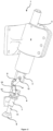
- the support mechanism (1) comprises a body (2), a motor (3) located on the body (2), a first rod (4) which is triggered by the motor (3) so as to be able to rotate clockwise or counter clockwise around its own axis, a transfer member (5) which is connected at one end to the first rod (4), a second rod (6) which is connected to the transfer member (5) and is able to make a radial rotational movement around its own axis together with the first rod (4) by means of the transfer member (5), a holder (7) which is located on the body (2), surrounds the second rod (6) and allows second rod (6) to be able to rotate around its own axis and also to move linearly along a direction that the second rod (6) extends, and at least one bearing (8) which is located on the second rod (6), moves towards or away from the weight (W) upon triggering of the first rod (4) by the motor (3), and contacts the weight (W) for supporting the weight (W) from at least one point.
- the support mechanism (1) of the present invention comprises a transfer member (5) which has a first bar (9) connected at one end to the first rod (4), and a second bar (10) connected at one end to the first bar (9) and at other end to the second rod (6), which allows the first rod (4) and the second rod (6) to move towards or away from each other during rotational movement around its own axis upon being triggered by the motor (3), and which is located between the first rod (4) and the second rod (6) ( Figure 1 ).
- the first rod (4) triggered by the motor (3) makes a rotational movement around its own axis.
- the second rod (6) rotates together with the first rod (4) by means of the transfer member (5) which is connected to the first rod (4) and the second rod (6).
- the second rod (6) surrounded by the holder (7) makes rotational movement around its own axis, it moves forward along the direction it extends to approach the weight (W). Therefore, the bearing (8) contacts the weight (W).
- the weight (W) is supported by the bearing (8) from at least one point.
- the first rod (4) rotates around its own axis, but this time in an opposite direction.
- the second rod (6) rotates around its own axis in an opposite direction by means of the transfer member (5).
- the second rod (6) moves along the direction that it extends by the reverse rotational movement around its own axis so as to be away from the weight (W). Therefore, contact of the weight (W) with the bearing (8) is ended.
- the transfer member (5) extends when bearing (8) approaches the weight (W), and the transfer member (5) retracts when bearing (8) moves away from the weight (W).
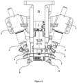
- the support mechanism (1) comprises a transfer member (5) having a first position (I) in which the first rod (4) and the second rod (6) are close to each other and a second position (II) to which the first rod is brought by being rotated around its own axis and in which the first rod (4) and the second rod (6) are away from each other, the transfer member having "V" form when in the second position (II). Having an "I" form when in the first position, the transfer member (5) takes the "V” form while switching from the first position (I) to the second position (II). Due to contracting and expanding structure of the transfer member (5), the support mechanism (1) easily reaches out the weight (W) and can easily be moved away from the weight (W) ( Figure 2 ).
- the support mechanism (1) comprises at least one gear path (11) which is located on the second rod (6) and/or the holder (7) and which allows the second rod (6) forward to move inside the holder (7) by rotating around its own axis.
- the gear path (11) is located on the second rod (6) and/or the holder (7). Thanks to the gear path (11) having an inclined structure, the second rod (6) can further make linear movement along the direction that it extends by rotating around its own axis.
- the support mechanism (1) comprises a first pin (12) connecting the first rod (4) and the first bar (9) with each other such that the first bar (9) can at least partially move around the connection axis, a second pin (13) connecting the second rod (6) and the second bar (10) with each other such that the second bar (10) can at least partially move around the connection axis and passing through the second bar (10) and the second rod (6), and a third pin (14) for connecting the first bar (9) and the second bar (10) so that they can at least partially move around the connection axis.
- the support mechanism (1) comprises a first pin (12) preferably having a cylindrical form, connecting the first rod (4) and the first bar (9) with each other such that first bar (9) can at least partially move around the connection axis and passing through the first bar (9) and the first rod (4), a second pin (13) preferably having a cylindrical form, connecting the second rod (6) and the second bar (10) with each other such that the second bar (10) can at least partially move around the connection axis and passing through the second bar (10) and the second rod (6), and a third pin (14) which preferably has a cylindrical form and provides connecting the first bar (9) and the second bar (10) so that they can at least partially move around the connection axis.
- the support mechanism (1) comprises at least one bearing (8) located on the second rod (6) in a spherically rotatable manner and extending outwards from the second rod (6).
- the bearing (8) is capable of rotating spherically where it is connected to the second rod (6).
- the bearing (8) can efficiently contact inclined surfaces of the weight (W).
- the support mechanism (1) comprises a weight (W), a bearing (8) contacting the weight (W), and a second rod (6) whose rotational movement around its own axis terminates depending on the power of motor (3) upon contact of the bearing (8) to the weight (W). Power of the motor (3) cannot be sufficient to compensate the frictional force created by contact of the bearing (8) to the weight (W). Thus, it is provided that the bearing (8) contacts the weight (W) so that it continues supporting the weight (W) only by the power of motor (3), without requiring any additional control mechanisms and/or systems.
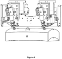
- the support mechanism (1) comprises at least one control unit (15) which controls operation of the motor (3). Thanks to the control unit (15), the support mechanism (1) is operated automatically ( Figure 3 ).
- the support mechanism (1) comprises a second rod (6) whose rotational movement around its own axis terminates upon contact of the bearing (8) to the weight (W) depending on the power of motor (3).
- Power of the motor (3) cannot be sufficient to compensate the frictional force created by contact of the bearing (8) to weight (W). Therefore, rotational movement of the second rod (6) around its own axis terminates only by the power of motor (3), without requiring any additional control mechanisms and/or systems ( Figure 4 ).
- the support mechanism (1) is suitable for use in balancing the weight (W) which is attached on the throwing unit (T) used in air vehicles to throw and/or release ammunition.
- the support mechanism (1) provides that the weight (W) attached to the throwing unit remains at a certain position or a predetermined position.
- the support mechanism (1) is suitable for use in a test device (D) of a throwing unit (T) which provides testing the throwing unit (T) used in air vehicles. Thanks to the support mechanism (1) located on the test device (D) for testing the throwing unit (T); it is provided that the weight (W) attached to the throwing unit (T) remains at a certain position or a predetermined position.
Landscapes
- Engineering & Computer Science (AREA)
- Aviation & Aerospace Engineering (AREA)
- Transmission Devices (AREA)
- Motorcycle And Bicycle Frame (AREA)
- Manipulator (AREA)
Claims (9)
- Trägermechanismus (1), der zum Tragen eines Gewichtes (W) ausgestaltet ist und versehen ist mit einen Körper (2), einem an dem Körper (2) angeordneten Motor (3), einer ersten Stange (4), die durch den Motor (3) angetrieben wird, um sich so im Uhrzeigersinn oder entgegen dem Uhrzeigersinn um ihre eigene Achse drehen zu können, einer Transferkomponente (5), die an einem Ende mit der ersten Stange (4) verbunden ist, einer zweiten Stange (6), die mit der Transferkomponente (5) verbunden ist und die dazu in der Lage ist, mittels der Transferkomponente (5) eine radiale Rotationsbewegung um ihre eigene Achse zusammen mit der ersten Stange (4) auszuführen, und wenigstens einem Lager (8), das an der zweiten Stange (6) angeordnet ist, das zur Bewegung zu dem Gewicht (W) hin oder davon weg bei Antrieb der ersten Stange (4) durch den Motor (3) ausgestaltet ist und das dazu ausgestaltet ist, in Kontakt mit dem Gewicht (W) zu kommen, um das Gewicht (W) an wenigstens einem Punkt zu halten, wobei die Transferkomponente (5) einen ersten Stab (9), der an einem Ende mit der ersten Stange (4) verbunden ist, und einen zweiten Stab (10) hat, der an einem Ende mit dem ersten Stab (9) und am anderen Ende mit der zweiten Stange (6) verbunden ist, dadurch gekennzeichnet, dass der Trägermechanismus weiterhin einen Halter (7) aufweist, der an dem Körper (2) angeordnet ist, dazu ausgestaltet ist, die zweite Stange (6) zu umgeben und es der zweiten Stange (6) zu ermöglichen, um ihre eigene Achse rotieren zu können und sich auch linear entlang einer Richtung bewegen zu können, in der die zweite Stange (6) ausgedehnt ist, wobei die Transferkomponente (5) und der Halter (7) es der ersten Stange (4) und der zweiten Stange (6) ermöglichen, sich während der Rotationsbewegung um die eigenen Achsen bei Antrieb durch den Motor (3) aufeinander zu oder voneinander weg zu bewegen, und wobei sich die Transferkomponente (5) zwischen der ersten Stange (4) und der zweiten Stange (6) befindet.
- Trägermechanismus (1) nach Anspruch 1, dadurch gekennzeichnet, dass die Transferkomponente (5) eine erste Stellung (I) hat, in der die erste Stange (4) und die zweite Stange (6) einander nahe sind, und eine zweite Stellung (II) hat, in die die erste Stange (6) durch Drehung um ihre eigene Achse gebracht wird und in der die erste Stange (4) und die zweite Stange (6) voneinander entfernt sind, und wobei die Transferkomponente (5) in der zweiten Stellung (II) eine V-Form hat.
- Trägermechanismus (1) nach Anspruch 1 oder 2, gekennzeichnet durch wenigstens einen Getriebegang (11), der an der zweiten Stange (6) und/oder dem Halter (7) angeordnet ist und der es ermöglicht, die zweite Stange (6) durch Drehen um ihre eigene Achse vorwärts in den Halter (7) zu bewegen.
- Trägermechanismus (1) nach einem der vorhergehenden Ansprüche, gekennzeichnet durch einen ersten Bolzen (12), der dazu ausgestaltet ist, die erste Stange (4) und den ersten Stab (9) miteinander zu verbinden, so dass der erste Stab (9) dazu in der Lage ist, sich wenigstens teilweise um die Verbindungsachse zu bewegen, durch einen zweiten Bolzen (13), der dazu ausgestaltet ist, die zweite Stange (6) und den zweiten Stab (10) miteinander zu verbinden, so dass der zweite Stab (10) dazu in der Lage ist, sich wenigstens teilweise um die Verbindungachse zu bewegen, und der dazu ausgestaltet ist, durch den zweiten Stab (10) und die zweite Stange (6) hindurch zu verlaufen, und durch einen dritten Bolzen (14), der dazu ausgestaltet ist, um den ersten Stab (9) und den zweiten Stab (10) miteinander zu verbinden, so dass sie dazu in der Lage sind, sich wenigstens teilweise um die Verbindungsachse zu bewegen.
- Trägermechanismus (1) nach einem der vorhergehenden Ansprüche, dadurch gekennzeichnet, dass das Lager (8) sich an der zweiten Stange (6) in einer sphärisch drehbaren Weise befindet und von der zweiten Stange (6) nach außen verläuft.
- Trägermechanismus (1) nach einem der vorhergehenden Ansprüche, dadurch gekennzeichnet, dass das Lager (8) dazu ausgestaltet ist, das Gewicht (W) zu kontaktieren, und dass die zweite Stange (6) dazu ausgestaltet ist, so dass die Drehbewegung um ihre eigene Achse abhängig von der Leistung des Motors (3) bei Kontakt des Lagers (8) mit dem Gewicht (W) aufhört.
- Trägermechanismus (1) nach einem der vorhergehenden Ansprüche, gekennzeichnet durch wenigstens eine Steuereinheit (15), die dazu eingerichtet ist, um den Betrieb des Motors (3) zu steuern.
- Trägermechanismus (1) nach einem der vorhergehenden Ansprüche, der dazu geeignet ist, dazu verwendet zu werden, das Gewicht (W) im Gleichgewicht zu halten, das an der Werfereinheit (T) angebracht ist, die in Luftfahrzeugen zum Werfen und/oder zur Freigabe von Geschossen verwendet wird.
- Trägermechanismus (1) nach einem der vorhergehenden Ansprüche, der geeignet ist, in einer Testvorrichtung einer Werfereinheit (T) verwendet zu werden, die zum Testen der in Luftfahrzeugen verwendeten Werfereinheit (T) dient.
Applications Claiming Priority (2)
| Application Number | Priority Date | Filing Date | Title |
|---|---|---|---|
| TR201811494 | 2018-08-08 | ||
| PCT/TR2019/050659 WO2020032900A1 (en) | 2018-08-08 | 2019-08-07 | A support mechanism |
Publications (3)
| Publication Number | Publication Date |
|---|---|
| EP3841014A1 EP3841014A1 (de) | 2021-06-30 |
| EP3841014A4 EP3841014A4 (de) | 2022-09-14 |
| EP3841014B1 true EP3841014B1 (de) | 2023-09-13 |
Family
ID=69413330
Family Applications (1)
| Application Number | Title | Priority Date | Filing Date |
|---|---|---|---|
| EP19847323.3A Active EP3841014B1 (de) | 2018-08-08 | 2019-08-07 | Stützmechanismus |
Country Status (3)
| Country | Link |
|---|---|
| US (1) | US11434006B2 (de) |
| EP (1) | EP3841014B1 (de) |
| WO (1) | WO2020032900A1 (de) |
Families Citing this family (1)
| Publication number | Priority date | Publication date | Assignee | Title |
|---|---|---|---|---|
| EP4408745A4 (de) * | 2021-09-30 | 2025-07-02 | Tusas Turk Havacilik Ve Uzay Sanayii Anonim Sirketi | Munitionsträgersystem |
Family Cites Families (9)
| Publication number | Priority date | Publication date | Assignee | Title |
|---|---|---|---|---|
| US2144893A (en) * | 1936-11-11 | 1939-01-24 | Automotive Prod Co Ltd | Fluid pressure operated jack |
| US2831400A (en) * | 1954-05-20 | 1958-04-22 | Brevets Aero Mecaniques | Devices for releasably holding the rear ends of rockets |
| US3059956A (en) * | 1958-01-21 | 1962-10-23 | Geffner Ted | Combined shackle and ejector mechanism for stores |
| US5932829A (en) * | 1997-09-11 | 1999-08-03 | Mcdonnell Douglas Corporation | Suspension and release rack apparatus capable of carrying both bombs and missiles |
| US7950607B1 (en) | 2006-04-10 | 2011-05-31 | Carleton Technologies, Inc. | Small munitions adaptor rack for releasing small munitions from an aircraft |
| KR101117102B1 (ko) | 2009-12-02 | 2012-02-22 | 국방과학연구소 | 접이식 날개의 전개 장치 및 이를 구비하는 비행체 |
| DE102010008729A1 (de) | 2010-02-20 | 2011-08-25 | Diehl BGT Defence GmbH & Co. KG, 88662 | Flugkörperabwurfvorrichtung |
| CN103072692A (zh) * | 2013-01-07 | 2013-05-01 | 大连理工大学 | 一种气动式高速投放装置 |
| CN105173086B (zh) | 2015-08-16 | 2017-03-22 | 启东市机关液化气有限责任公司 | 一种固定翼航模的改装导弹用挂架 |
-
2019
- 2019-08-07 EP EP19847323.3A patent/EP3841014B1/de active Active
- 2019-08-07 WO PCT/TR2019/050659 patent/WO2020032900A1/en not_active Ceased
- 2019-08-07 US US17/262,140 patent/US11434006B2/en active Active
Also Published As
| Publication number | Publication date |
|---|---|
| WO2020032900A1 (en) | 2020-02-13 |
| US20210347478A1 (en) | 2021-11-11 |
| US11434006B2 (en) | 2022-09-06 |
| EP3841014A1 (de) | 2021-06-30 |
| EP3841014A4 (de) | 2022-09-14 |
Similar Documents
| Publication | Publication Date | Title |
|---|---|---|
| EP3248737B1 (de) | Satellitengreifer | |
| EP3841014B1 (de) | Stützmechanismus | |
| US20060071120A1 (en) | Canard fin unit | |
| EP2597339A3 (de) | Schaltmechanismus, Getriebe und damit ausgestattetes Fahrzeug | |
| EP3480889A1 (de) | Sockelvorrichtung mit daran befestigter antenne mit fähigkeit zur biaxialen bewegung | |
| US20210247275A1 (en) | A test system for throwing mechanisms | |
| RU2619497C2 (ru) | Устройство удержания и освобождения раскрываемых элементов конструкции космических аппаратов | |
| GB2385310A (en) | Satellite launch assembly including means for connection and release | |
| CN114174020B (zh) | 用于机器人的驱动装置的制动设备 | |
| EP4357725A3 (de) | Abschussvorrichtung und vorrichtungen für schiesssportziele | |
| US2329404A (en) | Mast antenna actuator | |
| US11022187B2 (en) | Engagement device | |
| WO2001038767A2 (en) | Spherical swivel with elastomeric positioning device | |
| JP7123257B2 (ja) | 関節式機構およびその機構を備える関節式指向システム | |
| CN113646145A (zh) | 工具设备和方法 | |
| US20210239441A1 (en) | A test system for throwing mechanisms | |
| US7434762B2 (en) | Retractable thrust vector control vane system and method | |
| JPH0839462A (ja) | ロボットアーム構造 | |
| EP2608313B1 (de) | Antennenausrichtungssystem | |
| WO2023055325A1 (en) | A locking mechanism | |
| US10363856B1 (en) | Stowable payload carrier | |
| WO2021251930A2 (en) | A miniature, guided missile with control actuation system | |
| ES2925290B2 (es) | Dispositivo de agarre robótico | |
| KR102275964B1 (ko) | 하나의 스크류를 이용한 탄의 조종날개 구속해제 장치 및 구동방법 | |
| JP2020066335A (ja) | 移動システム |
Legal Events
| Date | Code | Title | Description |
|---|---|---|---|
| STAA | Information on the status of an ep patent application or granted ep patent |
Free format text: STATUS: THE INTERNATIONAL PUBLICATION HAS BEEN MADE |
|
| PUAI | Public reference made under article 153(3) epc to a published international application that has entered the european phase |
Free format text: ORIGINAL CODE: 0009012 |
|
| STAA | Information on the status of an ep patent application or granted ep patent |
Free format text: STATUS: REQUEST FOR EXAMINATION WAS MADE |
|
| 17P | Request for examination filed |
Effective date: 20210218 |
|
| AK | Designated contracting states |
Kind code of ref document: A1 Designated state(s): AL AT BE BG CH CY CZ DE DK EE ES FI FR GB GR HR HU IE IS IT LI LT LU LV MC MK MT NL NO PL PT RO RS SE SI SK SM TR |
|
| DAV | Request for validation of the european patent (deleted) | ||
| DAX | Request for extension of the european patent (deleted) | ||
| A4 | Supplementary search report drawn up and despatched |
Effective date: 20220818 |
|
| RIC1 | Information provided on ipc code assigned before grant |
Ipc: B64D 1/04 20060101AFI20220811BHEP |
|
| GRAP | Despatch of communication of intention to grant a patent |
Free format text: ORIGINAL CODE: EPIDOSNIGR1 |
|
| STAA | Information on the status of an ep patent application or granted ep patent |
Free format text: STATUS: GRANT OF PATENT IS INTENDED |
|
| INTG | Intention to grant announced |
Effective date: 20230316 |
|
| P01 | Opt-out of the competence of the unified patent court (upc) registered |
Effective date: 20230518 |
|
| GRAS | Grant fee paid |
Free format text: ORIGINAL CODE: EPIDOSNIGR3 |
|
| GRAA | (expected) grant |
Free format text: ORIGINAL CODE: 0009210 |
|
| STAA | Information on the status of an ep patent application or granted ep patent |
Free format text: STATUS: THE PATENT HAS BEEN GRANTED |
|
| AK | Designated contracting states |
Kind code of ref document: B1 Designated state(s): AL AT BE BG CH CY CZ DE DK EE ES FI FR GB GR HR HU IE IS IT LI LT LU LV MC MK MT NL NO PL PT RO RS SE SI SK SM TR |
|
| REG | Reference to a national code |
Ref country code: CH Ref legal event code: EP |
|
| REG | Reference to a national code |
Ref country code: DE Ref legal event code: R096 Ref document number: 602019037574 Country of ref document: DE |
|
| REG | Reference to a national code |
Ref country code: IE Ref legal event code: FG4D |
|
| REG | Reference to a national code |
Ref country code: LT Ref legal event code: MG9D |
|
| REG | Reference to a national code |
Ref country code: NL Ref legal event code: MP Effective date: 20230913 |
|
| PG25 | Lapsed in a contracting state [announced via postgrant information from national office to epo] |
Ref country code: GR Free format text: LAPSE BECAUSE OF FAILURE TO SUBMIT A TRANSLATION OF THE DESCRIPTION OR TO PAY THE FEE WITHIN THE PRESCRIBED TIME-LIMIT Effective date: 20231214 |
|
| PG25 | Lapsed in a contracting state [announced via postgrant information from national office to epo] |
Ref country code: SE Free format text: LAPSE BECAUSE OF FAILURE TO SUBMIT A TRANSLATION OF THE DESCRIPTION OR TO PAY THE FEE WITHIN THE PRESCRIBED TIME-LIMIT Effective date: 20230913 Ref country code: RS Free format text: LAPSE BECAUSE OF FAILURE TO SUBMIT A TRANSLATION OF THE DESCRIPTION OR TO PAY THE FEE WITHIN THE PRESCRIBED TIME-LIMIT Effective date: 20230913 Ref country code: NO Free format text: LAPSE BECAUSE OF FAILURE TO SUBMIT A TRANSLATION OF THE DESCRIPTION OR TO PAY THE FEE WITHIN THE PRESCRIBED TIME-LIMIT Effective date: 20231213 Ref country code: LV Free format text: LAPSE BECAUSE OF FAILURE TO SUBMIT A TRANSLATION OF THE DESCRIPTION OR TO PAY THE FEE WITHIN THE PRESCRIBED TIME-LIMIT Effective date: 20230913 Ref country code: LT Free format text: LAPSE BECAUSE OF FAILURE TO SUBMIT A TRANSLATION OF THE DESCRIPTION OR TO PAY THE FEE WITHIN THE PRESCRIBED TIME-LIMIT Effective date: 20230913 Ref country code: HR Free format text: LAPSE BECAUSE OF FAILURE TO SUBMIT A TRANSLATION OF THE DESCRIPTION OR TO PAY THE FEE WITHIN THE PRESCRIBED TIME-LIMIT Effective date: 20230913 Ref country code: GR Free format text: LAPSE BECAUSE OF FAILURE TO SUBMIT A TRANSLATION OF THE DESCRIPTION OR TO PAY THE FEE WITHIN THE PRESCRIBED TIME-LIMIT Effective date: 20231214 Ref country code: FI Free format text: LAPSE BECAUSE OF FAILURE TO SUBMIT A TRANSLATION OF THE DESCRIPTION OR TO PAY THE FEE WITHIN THE PRESCRIBED TIME-LIMIT Effective date: 20230913 |
|
| REG | Reference to a national code |
Ref country code: AT Ref legal event code: MK05 Ref document number: 1611038 Country of ref document: AT Kind code of ref document: T Effective date: 20230913 |
|
| PG25 | Lapsed in a contracting state [announced via postgrant information from national office to epo] |
Ref country code: NL Free format text: LAPSE BECAUSE OF FAILURE TO SUBMIT A TRANSLATION OF THE DESCRIPTION OR TO PAY THE FEE WITHIN THE PRESCRIBED TIME-LIMIT Effective date: 20230913 |
|
| PG25 | Lapsed in a contracting state [announced via postgrant information from national office to epo] |
Ref country code: IS Free format text: LAPSE BECAUSE OF FAILURE TO SUBMIT A TRANSLATION OF THE DESCRIPTION OR TO PAY THE FEE WITHIN THE PRESCRIBED TIME-LIMIT Effective date: 20240113 |
|
| PG25 | Lapsed in a contracting state [announced via postgrant information from national office to epo] |
Ref country code: AT Free format text: LAPSE BECAUSE OF FAILURE TO SUBMIT A TRANSLATION OF THE DESCRIPTION OR TO PAY THE FEE WITHIN THE PRESCRIBED TIME-LIMIT Effective date: 20230913 |
|
| PG25 | Lapsed in a contracting state [announced via postgrant information from national office to epo] |
Ref country code: ES Free format text: LAPSE BECAUSE OF FAILURE TO SUBMIT A TRANSLATION OF THE DESCRIPTION OR TO PAY THE FEE WITHIN THE PRESCRIBED TIME-LIMIT Effective date: 20230913 |
|
| PG25 | Lapsed in a contracting state [announced via postgrant information from national office to epo] |
Ref country code: SM Free format text: LAPSE BECAUSE OF FAILURE TO SUBMIT A TRANSLATION OF THE DESCRIPTION OR TO PAY THE FEE WITHIN THE PRESCRIBED TIME-LIMIT Effective date: 20230913 Ref country code: RO Free format text: LAPSE BECAUSE OF FAILURE TO SUBMIT A TRANSLATION OF THE DESCRIPTION OR TO PAY THE FEE WITHIN THE PRESCRIBED TIME-LIMIT Effective date: 20230913 Ref country code: IS Free format text: LAPSE BECAUSE OF FAILURE TO SUBMIT A TRANSLATION OF THE DESCRIPTION OR TO PAY THE FEE WITHIN THE PRESCRIBED TIME-LIMIT Effective date: 20240113 Ref country code: ES Free format text: LAPSE BECAUSE OF FAILURE TO SUBMIT A TRANSLATION OF THE DESCRIPTION OR TO PAY THE FEE WITHIN THE PRESCRIBED TIME-LIMIT Effective date: 20230913 Ref country code: EE Free format text: LAPSE BECAUSE OF FAILURE TO SUBMIT A TRANSLATION OF THE DESCRIPTION OR TO PAY THE FEE WITHIN THE PRESCRIBED TIME-LIMIT Effective date: 20230913 Ref country code: CZ Free format text: LAPSE BECAUSE OF FAILURE TO SUBMIT A TRANSLATION OF THE DESCRIPTION OR TO PAY THE FEE WITHIN THE PRESCRIBED TIME-LIMIT Effective date: 20230913 Ref country code: AT Free format text: LAPSE BECAUSE OF FAILURE TO SUBMIT A TRANSLATION OF THE DESCRIPTION OR TO PAY THE FEE WITHIN THE PRESCRIBED TIME-LIMIT Effective date: 20230913 Ref country code: SK Free format text: LAPSE BECAUSE OF FAILURE TO SUBMIT A TRANSLATION OF THE DESCRIPTION OR TO PAY THE FEE WITHIN THE PRESCRIBED TIME-LIMIT Effective date: 20230913 Ref country code: PT Free format text: LAPSE BECAUSE OF FAILURE TO SUBMIT A TRANSLATION OF THE DESCRIPTION OR TO PAY THE FEE WITHIN THE PRESCRIBED TIME-LIMIT Effective date: 20240115 |
|
| PG25 | Lapsed in a contracting state [announced via postgrant information from national office to epo] |
Ref country code: PL Free format text: LAPSE BECAUSE OF FAILURE TO SUBMIT A TRANSLATION OF THE DESCRIPTION OR TO PAY THE FEE WITHIN THE PRESCRIBED TIME-LIMIT Effective date: 20230913 |
|
| REG | Reference to a national code |
Ref country code: DE Ref legal event code: R097 Ref document number: 602019037574 Country of ref document: DE |
|
| PG25 | Lapsed in a contracting state [announced via postgrant information from national office to epo] |
Ref country code: DK Free format text: LAPSE BECAUSE OF FAILURE TO SUBMIT A TRANSLATION OF THE DESCRIPTION OR TO PAY THE FEE WITHIN THE PRESCRIBED TIME-LIMIT Effective date: 20230913 |
|
| PLBE | No opposition filed within time limit |
Free format text: ORIGINAL CODE: 0009261 |
|
| STAA | Information on the status of an ep patent application or granted ep patent |
Free format text: STATUS: NO OPPOSITION FILED WITHIN TIME LIMIT |
|
| PG25 | Lapsed in a contracting state [announced via postgrant information from national office to epo] |
Ref country code: DK Free format text: LAPSE BECAUSE OF FAILURE TO SUBMIT A TRANSLATION OF THE DESCRIPTION OR TO PAY THE FEE WITHIN THE PRESCRIBED TIME-LIMIT Effective date: 20230913 |
|
| 26N | No opposition filed |
Effective date: 20240614 |
|
| PG25 | Lapsed in a contracting state [announced via postgrant information from national office to epo] |
Ref country code: SI Free format text: LAPSE BECAUSE OF FAILURE TO SUBMIT A TRANSLATION OF THE DESCRIPTION OR TO PAY THE FEE WITHIN THE PRESCRIBED TIME-LIMIT Effective date: 20230913 |
|
| PG25 | Lapsed in a contracting state [announced via postgrant information from national office to epo] |
Ref country code: SI Free format text: LAPSE BECAUSE OF FAILURE TO SUBMIT A TRANSLATION OF THE DESCRIPTION OR TO PAY THE FEE WITHIN THE PRESCRIBED TIME-LIMIT Effective date: 20230913 |
|
| PG25 | Lapsed in a contracting state [announced via postgrant information from national office to epo] |
Ref country code: BG Free format text: LAPSE BECAUSE OF FAILURE TO SUBMIT A TRANSLATION OF THE DESCRIPTION OR TO PAY THE FEE WITHIN THE PRESCRIBED TIME-LIMIT Effective date: 20230913 |
|
| PG25 | Lapsed in a contracting state [announced via postgrant information from national office to epo] |
Ref country code: BG Free format text: LAPSE BECAUSE OF FAILURE TO SUBMIT A TRANSLATION OF THE DESCRIPTION OR TO PAY THE FEE WITHIN THE PRESCRIBED TIME-LIMIT Effective date: 20230913 |
|
| REG | Reference to a national code |
Ref country code: DE Ref legal event code: R119 Ref document number: 602019037574 Country of ref document: DE |
|
| REG | Reference to a national code |
Ref country code: CH Ref legal event code: PL |
|
| PG25 | Lapsed in a contracting state [announced via postgrant information from national office to epo] |
Ref country code: LU Free format text: LAPSE BECAUSE OF NON-PAYMENT OF DUE FEES Effective date: 20240807 |
|
| PG25 | Lapsed in a contracting state [announced via postgrant information from national office to epo] |
Ref country code: CH Free format text: LAPSE BECAUSE OF NON-PAYMENT OF DUE FEES Effective date: 20240831 Ref country code: MC Free format text: LAPSE BECAUSE OF FAILURE TO SUBMIT A TRANSLATION OF THE DESCRIPTION OR TO PAY THE FEE WITHIN THE PRESCRIBED TIME-LIMIT Effective date: 20230913 |
|
| REG | Reference to a national code |
Ref country code: BE Ref legal event code: MM Effective date: 20240831 |
|
| PG25 | Lapsed in a contracting state [announced via postgrant information from national office to epo] |
Ref country code: DE Free format text: LAPSE BECAUSE OF NON-PAYMENT OF DUE FEES Effective date: 20250301 |
|
| PG25 | Lapsed in a contracting state [announced via postgrant information from national office to epo] |
Ref country code: BE Free format text: LAPSE BECAUSE OF NON-PAYMENT OF DUE FEES Effective date: 20240831 |
|
| PG25 | Lapsed in a contracting state [announced via postgrant information from national office to epo] |
Ref country code: IE Free format text: LAPSE BECAUSE OF NON-PAYMENT OF DUE FEES Effective date: 20240807 |
|
| PGFP | Annual fee paid to national office [announced via postgrant information from national office to epo] |
Ref country code: IT Payment date: 20250822 Year of fee payment: 7 |
|
| PGFP | Annual fee paid to national office [announced via postgrant information from national office to epo] |
Ref country code: GB Payment date: 20250822 Year of fee payment: 7 |
|
| PGFP | Annual fee paid to national office [announced via postgrant information from national office to epo] |
Ref country code: FR Payment date: 20250821 Year of fee payment: 7 |