EP3840188A1 - Rotating electrical machine - Google Patents
Rotating electrical machine Download PDFInfo
- Publication number
- EP3840188A1 EP3840188A1 EP18930497.5A EP18930497A EP3840188A1 EP 3840188 A1 EP3840188 A1 EP 3840188A1 EP 18930497 A EP18930497 A EP 18930497A EP 3840188 A1 EP3840188 A1 EP 3840188A1
- Authority
- EP
- European Patent Office
- Prior art keywords
- groove
- electrical machine
- rotating electrical
- terminal
- conductive member
- Prior art date
- Legal status (The legal status is an assumption and is not a legal conclusion. Google has not performed a legal analysis and makes no representation as to the accuracy of the status listed.)
- Granted
Links
Images



Classifications
-
- H—ELECTRICITY
- H02—GENERATION; CONVERSION OR DISTRIBUTION OF ELECTRIC POWER
- H02K—DYNAMO-ELECTRIC MACHINES
- H02K3/00—Details of windings
- H02K3/46—Fastening of windings on the stator or rotor structure
- H02K3/50—Fastening of winding heads, equalising connectors, or connections thereto
-
- H—ELECTRICITY
- H02—GENERATION; CONVERSION OR DISTRIBUTION OF ELECTRIC POWER
- H02K—DYNAMO-ELECTRIC MACHINES
- H02K3/00—Details of windings
- H02K3/32—Windings characterised by the shape, form or construction of the insulation
- H02K3/325—Windings characterised by the shape, form or construction of the insulation for windings on salient poles, such as claw-shaped poles
-
- H—ELECTRICITY
- H02—GENERATION; CONVERSION OR DISTRIBUTION OF ELECTRIC POWER
- H02K—DYNAMO-ELECTRIC MACHINES
- H02K3/00—Details of windings
- H02K3/46—Fastening of windings on the stator or rotor structure
- H02K3/52—Fastening salient pole windings or connections thereto
-
- H—ELECTRICITY
- H02—GENERATION; CONVERSION OR DISTRIBUTION OF ELECTRIC POWER
- H02K—DYNAMO-ELECTRIC MACHINES
- H02K3/00—Details of windings
- H02K3/46—Fastening of windings on the stator or rotor structure
- H02K3/52—Fastening salient pole windings or connections thereto
- H02K3/521—Fastening salient pole windings or connections thereto applicable to stators only
- H02K3/522—Fastening salient pole windings or connections thereto applicable to stators only for generally annular cores with salient poles
-
- H—ELECTRICITY
- H02—GENERATION; CONVERSION OR DISTRIBUTION OF ELECTRIC POWER
- H02K—DYNAMO-ELECTRIC MACHINES
- H02K5/00—Casings; Enclosures; Supports
- H02K5/04—Casings or enclosures characterised by the shape, form or construction thereof
- H02K5/22—Auxiliary parts of casings not covered by groups H02K5/06-H02K5/20, e.g. shaped to form connection boxes or terminal boxes
- H02K5/225—Terminal boxes or connection arrangements
-
- H—ELECTRICITY
- H02—GENERATION; CONVERSION OR DISTRIBUTION OF ELECTRIC POWER
- H02K—DYNAMO-ELECTRIC MACHINES
- H02K2203/00—Specific aspects not provided for in the other groups of this subclass relating to the windings
- H02K2203/09—Machines characterised by wiring elements other than wires, e.g. bus rings, for connecting the winding terminations
-
- H—ELECTRICITY
- H02—GENERATION; CONVERSION OR DISTRIBUTION OF ELECTRIC POWER
- H02K—DYNAMO-ELECTRIC MACHINES
- H02K2213/00—Specific aspects, not otherwise provided for and not covered by codes H02K2201/00 - H02K2211/00
- H02K2213/03—Machines characterised by numerical values, ranges, mathematical expressions or similar information
Definitions
- the present disclosure relates to a rotating electrical machine including a coil connection body.
- a coil connection body of a rotating electrical machine there is a structure in which arc-shaped conductive members are provided in a plurality of grooves formed concentrically in a holder which is an insulating member made of resin.
- the conductive member provided at a predetermined position in the groove of the holder is connected to an end of a coil wound around a tooth of a stator and is subjected to predetermined wire connection.
- the conductive member once inserted in the groove is lifted by impact during conveyance, an external load during assembly, or the like, thus leading to deterioration of productivity in the later process of connecting the conductive member and an end of a coil, reduction of insulation property between the conductive members, and the like.
- the conductive member that is small in the length dimension in the circumferential direction of the arc part a fitting part thereof to the holder is short, and thus the conductive member readily comes off.
- the groove is formed to be wider than the conductive member, and a projection to contact with the conductive member is provided in the groove, whereby the conductive member is inhibited from moving in the groove or coming off from the groove.
- Patent Document 1 Japanese Laid-Open Patent Publication No. 2005-304278
- the present disclosure has been made to solve the above problems, and an object of the present disclosure is to provide a rotating electrical machine in which lifting and coming-off of a conductive member held by a holder of a coil connection body are inhibited, thus achieving high assemblability and high insulation property.
- a rotating electrical machine is a rotating electrical machine including an annular coil connection body provided coaxially with a stator, wherein the coil connection body includes an insulting holder made of resin and having a plurality of grooves provided coaxially, and a conductive member held in the groove and connected to an end of a coil wound around a tooth of the stator, each groove has an overhang portion provided at a groove opening side relative to the conductive member on one side wall and restricting an axial-direction movement of the conductive member, and a positioning projection provided at a position opposed in a radial direction to the conductive member on another side wall, and restricting a radial-direction movement of the conductive member.
- the overhang portion for restricting an axial-direction movement of the conductive member and the positioning projection for restricting a radial-direction movement of the conductive member are provided in the groove provided on the insulting holder of the coil connection body.
- FIG. 1 is a sectional view showing a rotating electrical machine according to embodiment 1
- FIG. 2 is a top view showing a coil connection body of the rotating electrical machine according to embodiment 1
- FIG. 3 is a sectional view of a part indicated by A-A in FIG. 2
- FIG. 4 is a partial sectional view showing a holder of the coil connection body according to embodiment 1.
- arrow Z indicates the axial direction of the rotating electrical machine
- arrow R indicates the radial direction of the rotating electrical machine.
- a rotating electrical machine 100 according to embodiment 1 is used for an electric power steering driving motor or the like, and as shown in FIG. 1 , a stator 2 is press-fitted and fixed to the inner circumference of a frame 1.
- a rotor 3 is rotatably provided on the inner circumferential side of the stator 2.
- the rotor 3 is fixed to a rotary shaft 4 inserted at the axial position, and has permanent magnets.
- the rotor 3 is not limited to a permanent magnet rotor, but may be a squirrel-cage rotor, a winding rotor, or the like.
- the stator 2 includes a stator core formed by arranging, in an annular shape, a plurality of divided cores each formed by stacking electromagnetic steel sheets.
- Each divided core has an arc-shaped core back portion and a tooth protruding inward in the radial direction from the inner circumferential wall surface of the core back portion.
- Each divided core is provided with a bobbin which is an insulating member, and a coil 5 for U phase, V phase, or W phase is wound around the tooth with the bobbin therebetween.
- An end of the coil 5 is subjected to predetermined wire connection by an annular coil connection body 6 provided coaxially with the stator 2.
- the coil connection body 6 includes an insulting holder (hereinafter, holder 7) made of resin, and a power supply terminal (hereinafter, terminal 9) which is a conductive member to be connected to the end of the coil 5.
- the holder 7 has a plurality of grooves 8 arranged concentrically.
- the terminal 9 has an arc portion 91 held in the groove 8 of the holder 7, and a hook portion 92 provided on the upper side of the arc portion 91.
- the terminal 9 is held at a predetermined position in the groove 8 of the holder 7, and is connected to an end of the coil 5 wound around the tooth of the divided core.
- H indicates the dimension in the axial direction
- W indicates the dimension in the radial direction.
- the holder 7 shown in FIG. 3 and FIG. 4 has three grooves 8 arranged concentrically, and the sectional shapes inside the grooves 8 are the same. Therefore, some of reference characters are omitted in the drawings.
- the groove 8 of the holder 7 has a groove opening 81 and a bottom portion 82 which are located at ends in the axial direction, and side walls 83, 84 opposed to each other in the radial direction.
- Each groove 8 has an overhang portion 85 provided on the groove opening 81 side relative to the terminal 9 on one of the side walls (here, side wall 83 on the inner circumferential side), and a positioning projection 86 provided at a position opposed in the radial direction to the terminal 9 on the other side wall (here, side wall 84 on the outer circumferential side).
- the overhang portion 85 is provided at the side wall 83 on the inner circumferential side and the positioning projection 86 is provided at the side wall 84 on the outer circumferential side in embodiment 1, these may be reversed from each other.
- a terminal holding portion 87 corresponding to the predetermined position of the terminal 9 is a space surrounded by a dotted-dashed line shown in FIG. 4 , a side surface 85b of the overhang portion 85, the one side wall 83, the bottom portion 82, and a top portion 86a of the positioning projection 86.
- the terminal 9 held at the terminal holding portion 87 is restricted from moving in the axial direction, by the overhang portion 85, and restricted from moving in the radial direction, by the positioning projection 86. That is, the overhang portion 85 prevents lifting and coming-off of the terminal 9, and the positioning projection 86 positions the terminal 9 such that a part of the terminal 9 overlaps the overhang portion 85 in the axial direction.
- the width dimension of the terminal 9 is denoted by W1
- the height dimension of the terminal 9 is denoted by H1
- the width dimension of the groove opening 81 is denoted by W2
- the width dimension of the bottom portion 82 is denoted by W3
- the interval between a top portion 85a of the overhang portion 85 and the top portion 86a of the positioning projection 86 is denoted by W4
- the interval between the side wall 83 and the side wall 84 is denoted by W5.
- the height dimension from the bottom portion 82 of the groove 8 to the side surface 85b of the overhang portion 85 is denoted by H2
- the height dimension from the groove opening 81 to the positioning projection 86 is denoted by H3.
- the width dimension W2 of the groove opening 81 is set to be greater than the width dimension W1 of the terminal 9 so that the terminal 9 can be inserted (W2 > W1).
- the width dimension W3 of the bottom portion 82 is set to be greater than the width dimension W1 of the terminal 9 so that the terminal 9 can be held (W3 > W1).
- the height dimension H2 from the bottom portion 82 to the side surface 85b of the overhang portion 85 is set to be greater than the height dimension H1 of the terminal 9 so that the terminal 9 can be held (H2 > H1). It is noted that the greater the values of W2, W3, and H2 are, the greater the device size is. Therefore, it is desirable that these values are set to be smaller within a range that allows insertion and holding of the terminal 9.
- the height dimension H3 from the groove opening 81 to the positioning projection 86 is set to such a height that the terminal 9 can be inserted to the terminal holding portion 87 and insulation property of the terminal 9 can be ensured. If H3 is great, the device size becomes large, whereas if H3 is small, it becomes difficult to ensure insulation property of the terminal 9. Therefore, it is desirable that H3 is set to be smaller within a range that can ensure insulation property.
- the axial-direction sectional shapes of the overhang portion 85 and the positioning projection 86 are rectangular.
- the interval W4 between the top portions 85a, 86a of the overhang portion 85 and the positioning projection 86 is set to be smaller than the width dimension W1 of the terminal 9 (W4 ⁇ W1).
- the sectional shapes of the overhang portion 85 and the positioning projection 86 are not limited to rectangular shapes. In the case where the sectional shapes of the overhang portion 85 and the positioning projection 86 are shapes other than rectangular shapes (see FIG. 5 ), an interval W4' between the most protruding parts in the radial direction of the overhang portion 85 and the positioning projection 86 is set to be smaller than the width dimension W1 of the terminal 9 (W4' ⁇ W1).
- the overhang portion 85 and the positioning projection 86 may be provided over the entire circumference of the groove 8, or may be partially provided. In the case where the overhang portion 85 and the positioning projection 86 are partially provided, the radial-direction dimension of the groove opening at a part where the overhang portion 85 and the positioning projection 86 are not provided is W5 (W5 > W2), so that the terminal 9 can be easily inserted in attachment work.
- a projection provided in the groove ensures contact between the holder and the terminal and thus prevents lifting and coming-off of the terminal.
- the width dimension of the groove is smaller than a design value, it is necessary to increase a load in attachment work, so that assemblability is deteriorated, and if the width dimension of the groove is greater than the design value, contact between the holder and the terminal cannot be ensured. Therefore, high dimensional accuracy is required for the holder.
- the terminal 9 comes into contact with the side surface 85b of the overhang portion 85 when the terminal 9 moves in a direction toward the groove opening 81. That is, it is not necessary that the terminal 9 held at the terminal holding portion 87 is constantly in contact with the overhang portion 85 and the positioning projection 86. Therefore, it is not necessary to strictly set the dimensional tolerance between the groove 8 and the terminal 9. In addition, high dimensional accuracy is not required for the holder 7, so that manufacturing becomes easy. Further, a large load is not needed in attachment work, and thus assemblability is excellent.
- the overhang portion 85 for restricting axial-direction movement of the terminal 9 and the positioning projection 86 for restricting radial-direction movement of the terminal 9 are provided in the groove 8 formed in the holder 7 of the coil connection body 6.
- the rotating electrical machine 100 that is high in assemblability and insulation property is obtained.
- FIG. 5 to FIG. 7 are partial sectional views showing the coil connection body according to embodiment 2.
- Holders 7A, 7B, 7 shown in FIG. 5 to FIG. 7 each have three grooves 8 arranged concentrically, and the sectional shapes inside the grooves 8 are the same. Therefore, some of reference characters are omitted in the drawings.
- the entire structure of the rotating electrical machine according to embodiment 2 is the same as in the above embodiment 1, and therefore the description thereof is omitted here.
- the holder 7A shown in FIG. 5 has a slope portion 85c for expanding the width dimension W2 of the groove opening 81, on the overhang portion 85 provided on the one side wall 83.
- the holder 7A has a slope portion 84a for expanding the width dimension W2 of the groove opening 81, on the other side wall 84.
- a partition portion between the adjacent grooves 8 of the holder 7A has a taper shape tapered toward the distal end.
- the holder 7A has a slope portion 86b at a corner on the groove opening 81 side of the positioning projection 86.
- the holder 7B shown in FIG. 6 has a curved surface portion 85d for expanding the width dimension W2 of the groove opening 81, on the overhang portion 85 provided on the one side wall 83.
- the holder 7B has a curved surface portion 84b for expanding the width dimension W2 of the groove opening 81, on the other side wall 84.
- the holder 7B has a curved surface portion 86c at a corner on the groove opening 81 side of the positioning projection 86.
- the slope portion 84a or the curved surface portion 84b is formed on the side wall 84, and the slope portion 85c or the curved surface portion 85d is formed on the groove opening 81 side of the overhang portion 85, so as to expand the width dimension W2 of the groove opening 81.
- the slope portion or the curved surface portion is formed on both of the side wall 84 and the overhang portion 85, but may be formed on one of the side wall 84 and the overhang portion 85.
- the terminal 9 shown in FIG. 7 has a slope portion 9a at a corner opposed to the positioning projection 86 and the bottom portion 82 of the groove 8. Instead of the slope portion 9a, a curved surface portion may be provided. Such a configuration also makes it easy to attach the terminal 9.
- a configuration in which the terminal 9 shown in FIG. 7 is combined with the holder 7A (7B) shown in FIG. 5 (or FIG. 6 ) may be adopted, whereby attachment of the terminal 9 becomes easier. According to embodiment 2, the same effects as in the above embodiment 1 are provided and in addition, attachment of the terminal 9 to the holder 7 becomes easy and thus assemblability is further improved.
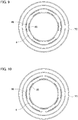
- FIG. 8 to FIG. 10 are top views showing arrangement examples of the overhang portions and the positioning projections in the coil connection body according to embodiment 3.
- the overhang portions 85 and the positioning projections 86 are shown in only the groove 8 on the innermost circumference, but the same structure applies also to the other grooves 8.
- the entire structure of the rotating electrical machine according to embodiment 3 is the same as in the above embodiment 1, and therefore the description thereof is omitted here.
- the overhang portion 85 and the positioning projection 86 are provided over the entire circumference of each groove 8.
- the holder 7 configured as described above can assuredly inhibit lifting of the terminal 9, thus obtaining high holding property. Meanwhile, the contact area with the terminal 9 in attachment work becomes large.
- the overhang portions 85 and the positioning projections 86 are partially provided at intervals in the circumferential direction in each groove 8 of holders 7C, 7D.
- the overhang portions 85 and the positioning projections 86 are arranged so as to overlap each other in the radial direction, and in the holder 7D shown in FIG. 10 , the overhang portions 85 and the positioning projections 86 are arranged alternately so as not to overlap each other in the radial direction.
- a plurality of terminals 9 are attached in the groove 8 of one holder. Then, the overhang portion 85 and the positioning projection 86 need to be provided in at least one location in a zone where the arc portion 91 of the terminal 9 is provided.
- the length dimension in the circumferential direction of the overhang portion 85 is small, holding property for the terminal 9 is low, so that the terminal 9 might be lifted at a location away from the overhang portion 85. Therefore, in the case where the length dimension in the circumferential direction of the overhang portion 85 is small, it is desirable to provide one overhang portion 85 at each of vicinities of both ends in the zone where the terminal 9 is provided.
- the arrangement of the overhang portion 85 and the positioning projection 86 is not limited to the examples shown in FIG. 8 to FIG. 10 , but may be modified in various manners.
- the overhang portion 85 and the positioning projection 86 need not be equal to each other in the length dimension in the circumferential direction and in the width dimension in the radial direction, and also, the intervals in their intermittent arrangements need not be equal pitches.
- the same effects as in the above embodiment 1 are provided and in addition, owing to the partial arrangements of the overhang portions 85 and the positioning projections 86, assemblability is improved and lifting and coming-off of the terminal 9 can be efficiently inhibited.
- FIG. 11 is a top view showing the holder in the coil connection body according to embodiment 4
- FIG. 12 is a partial sectional view showing the coil connection body according to embodiment 4.
- the entire structure of the rotating electrical machine according to embodiment 4 is the same as in the above embodiment 1, and therefore the description thereof is omitted here.
- a holder 7E according to embodiment 4 has a through hole 71 in the bottom portion 82 of the groove 8 which is opposed to the overhang portion 85, thus making it easy to mold the overhang portion 85.
- a lower mold used in molding work for the holder 7E has a mold part (i.e., pin) that can pass through the through hole 71 and reach the overhang portion 85.
- the pin of the lower mold is extended to the inside of the groove 8 from the position of the through hole 71 and fixed at the position of the side surface 85b of the overhang portion 85, and in this state, resin is cured.
- the holder 7E having the overhang portion 85 and the through hole 71 is formed.
- the size of the through hole 71 should be as small as possible in view of ensuring stiffness of the holder 7E, and it is desirable that the size of the through hole 71 is approximately equal to the size of the overhang portion 85.
- the overhang portion 85 can be formed by conventional molding work only, without the need of a special working process, whereby the manufacturing process can be simplified.
- the manufacturing method for the holder having the overhang portion 85 is not limited to the method described in embodiment 4.
- the holder having the overhang portion 85 can be manufactured using biaxial operation in the up-down direction and the circumferential direction for operation of a mold, or by molding using a 3D printer.
Landscapes
- Engineering & Computer Science (AREA)
- Power Engineering (AREA)
- Insulation, Fastening Of Motor, Generator Windings (AREA)
Abstract
Description
- The present disclosure relates to a rotating electrical machine including a coil connection body.
- As a coil connection body of a rotating electrical machine, there is a structure in which arc-shaped conductive members are provided in a plurality of grooves formed concentrically in a holder which is an insulating member made of resin. The conductive member provided at a predetermined position in the groove of the holder is connected to an end of a coil wound around a tooth of a stator and is subjected to predetermined wire connection. In a conventional coil connection body, the conductive member once inserted in the groove is lifted by impact during conveyance, an external load during assembly, or the like, thus leading to deterioration of productivity in the later process of connecting the conductive member and an end of a coil, reduction of insulation property between the conductive members, and the like. In particular, in the case of the conductive member that is small in the length dimension in the circumferential direction of the arc part, a fitting part thereof to the holder is short, and thus the conductive member readily comes off.
- Meanwhile, in the case of strictly setting the dimensional tolerance between the groove and the conductive member in order to prevent the conductive member from coming off, if the conductive member or the groove is deformed, it becomes difficult to fit the conductive member, so that assemblability is reduced. In order to solve such a problem, in Patent Document 1, the groove is formed to be wider than the conductive member, and a projection to contact with the conductive member is provided in the groove, whereby the conductive member is inhibited from moving in the groove or coming off from the groove.
- Patent Document 1: Japanese Laid-Open Patent Publication No.
2005-304278 - However, in the configuration in which contact with the conductive member is ensured by the projection provided in the groove to prevent lifting of the conductive member as in Patent Document 1, if the width dimension of the groove becomes smaller than a design value due to deformation of the holder or the like, a load in attachment work for press-fitting the conductive member into the holder increases, thus deteriorating assemblability. On the other hand, if the width dimension of the groove becomes greater than the design value due to deformation of the holder or the like, contact between the projection and the conductive member cannot be ensured, and therefore lifting of the conductive member cannot be inhibited.
- The present disclosure has been made to solve the above problems, and an object of the present disclosure is to provide a rotating electrical machine in which lifting and coming-off of a conductive member held by a holder of a coil connection body are inhibited, thus achieving high assemblability and high insulation property.
- A rotating electrical machine according to the present disclosure is a rotating electrical machine including an annular coil connection body provided coaxially with a stator, wherein the coil connection body includes an insulting holder made of resin and having a plurality of grooves provided coaxially, and a conductive member held in the groove and connected to an end of a coil wound around a tooth of the stator, each groove has an overhang portion provided at a groove opening side relative to the conductive member on one side wall and restricting an axial-direction movement of the conductive member, and a positioning projection provided at a position opposed in a radial direction to the conductive member on another side wall, and restricting a radial-direction movement of the conductive member.
- In the rotating electrical machine according to the present disclosure, the overhang portion for restricting an axial-direction movement of the conductive member and the positioning projection for restricting a radial-direction movement of the conductive member are provided in the groove provided on the insulting holder of the coil connection body. Thus, with a simple structure, lifting and coming-off of the conductive member can be inhibited, whereby assemblability and insulation property can be improved.
- Objects, features, aspects, and effects of the present disclosure other than the above will become more apparent from the following detailed description with reference to the drawings.
-
- [
FIG. 1] FIG. 1 is a sectional view showing a rotating electrical machine according to embodiment 1. - [
FIG. 2] FIG. 2 is a top view showing a coil connection body of the rotating electrical machine according to embodiment 1. - [
FIG. 3] FIG. 3 is a partial sectional view showing the coil connection body according to embodiment 1. - [
FIG. 4] FIG. 4 is a partial sectional view showing a holder of the coil connection body according to embodiment 1. - [
FIG. 5] FIG. 5 is a partial sectional view showing a coil connection body according toembodiment 2. - [
FIG. 6] FIG. 6 is a partial sectional view showing another coil connection body according toembodiment 2. - [
FIG. 7] FIG. 7 is a partial sectional view showing still another coil connection body according toembodiment 2. - [
FIG. 8] FIG. 8 is a top view showing an arrangement example of overhang portions and positioning projections in a coil connection body according toembodiment 3. - [
FIG. 9] FIG. 9 is a top view showing another arrangement example of overhang portions and positioning projections in the coil connection body according toembodiment 3. - [
FIG. 10] FIG. 10 is a top view showing still another arrangement example of overhang portions and positioning projections in the coil connection body according toembodiment 3. - [
FIG. 11] FIG. 11 is a top view showing a holder in a coil connection body according toembodiment 4. - [
FIG. 12] FIG. 12 is a partial sectional view showing the coil connection body according toembodiment 4. - Hereinafter, a rotating electrical machine according to embodiment 1 will be described with reference to the drawings.
FIG. 1 is a sectional view showing a rotating electrical machine according to embodiment 1,FIG. 2 is a top view showing a coil connection body of the rotating electrical machine according to embodiment 1, andFIG. 3 is a sectional view of a part indicated by A-A inFIG. 2 .FIG. 4 is a partial sectional view showing a holder of the coil connection body according to embodiment 1. In the drawings, the same or corresponding parts are denoted by the same reference characters. In the drawings, arrow Z indicates the axial direction of the rotating electrical machine, and arrow R indicates the radial direction of the rotating electrical machine. - A rotating
electrical machine 100 according to embodiment 1 is used for an electric power steering driving motor or the like, and as shown inFIG. 1 , astator 2 is press-fitted and fixed to the inner circumference of a frame 1. Arotor 3 is rotatably provided on the inner circumferential side of thestator 2. Therotor 3 is fixed to arotary shaft 4 inserted at the axial position, and has permanent magnets. However, therotor 3 is not limited to a permanent magnet rotor, but may be a squirrel-cage rotor, a winding rotor, or the like. - The
stator 2 includes a stator core formed by arranging, in an annular shape, a plurality of divided cores each formed by stacking electromagnetic steel sheets. Each divided core has an arc-shaped core back portion and a tooth protruding inward in the radial direction from the inner circumferential wall surface of the core back portion. Each divided core is provided with a bobbin which is an insulating member, and acoil 5 for U phase, V phase, or W phase is wound around the tooth with the bobbin therebetween. An end of thecoil 5 is subjected to predetermined wire connection by an annularcoil connection body 6 provided coaxially with thestator 2. - As shown in
FIG. 2 , thecoil connection body 6 includes an insulting holder (hereinafter, holder 7) made of resin, and a power supply terminal (hereinafter, terminal 9) which is a conductive member to be connected to the end of thecoil 5. Theholder 7 has a plurality ofgrooves 8 arranged concentrically. Theterminal 9 has anarc portion 91 held in thegroove 8 of theholder 7, and ahook portion 92 provided on the upper side of thearc portion 91. Theterminal 9 is held at a predetermined position in thegroove 8 of theholder 7, and is connected to an end of thecoil 5 wound around the tooth of the divided core. - The internal structure of the
groove 8 formed in theholder 7 of thecoil connection body 6, and the positional relationship thereof with theterminal 9, will be described in detail with reference toFIG. 3 andFIG. 4 . In the drawings, H indicates the dimension in the axial direction, and W indicates the dimension in the radial direction. Theholder 7 shown inFIG. 3 andFIG. 4 has threegrooves 8 arranged concentrically, and the sectional shapes inside thegrooves 8 are the same. Therefore, some of reference characters are omitted in the drawings. - As shown in
FIG. 4 , thegroove 8 of theholder 7 has a groove opening 81 and abottom portion 82 which are located at ends in the axial direction, andside walls groove 8 has anoverhang portion 85 provided on the groove opening 81 side relative to theterminal 9 on one of the side walls (here,side wall 83 on the inner circumferential side), and apositioning projection 86 provided at a position opposed in the radial direction to theterminal 9 on the other side wall (here,side wall 84 on the outer circumferential side). Although theoverhang portion 85 is provided at theside wall 83 on the inner circumferential side and thepositioning projection 86 is provided at theside wall 84 on the outer circumferential side in embodiment 1, these may be reversed from each other. - A
terminal holding portion 87 corresponding to the predetermined position of theterminal 9 is a space surrounded by a dotted-dashed line shown inFIG. 4 , aside surface 85b of theoverhang portion 85, the oneside wall 83, thebottom portion 82, and atop portion 86a of thepositioning projection 86. Theterminal 9 held at theterminal holding portion 87 is restricted from moving in the axial direction, by theoverhang portion 85, and restricted from moving in the radial direction, by thepositioning projection 86. That is, theoverhang portion 85 prevents lifting and coming-off of theterminal 9, and thepositioning projection 86 positions theterminal 9 such that a part of theterminal 9 overlaps theoverhang portion 85 in the axial direction. - As shown in
FIG. 3 andFIG. 4 , the width dimension of theterminal 9 is denoted by W1, the height dimension of theterminal 9 is denoted by H1, the width dimension of thegroove opening 81 is denoted by W2, the width dimension of thebottom portion 82 is denoted by W3, the interval between atop portion 85a of theoverhang portion 85 and thetop portion 86a of thepositioning projection 86 is denoted by W4, and the interval between theside wall 83 and theside wall 84 is denoted by W5. In addition, the height dimension from thebottom portion 82 of thegroove 8 to theside surface 85b of theoverhang portion 85 is denoted by H2, and the height dimension from the groove opening 81 to thepositioning projection 86 is denoted by H3. - The width dimension W2 of the
groove opening 81 is set to be greater than the width dimension W1 of theterminal 9 so that theterminal 9 can be inserted (W2 > W1). The width dimension W3 of thebottom portion 82 is set to be greater than the width dimension W1 of theterminal 9 so that theterminal 9 can be held (W3 > W1). Similarly, the height dimension H2 from thebottom portion 82 to theside surface 85b of theoverhang portion 85 is set to be greater than the height dimension H1 of theterminal 9 so that theterminal 9 can be held (H2 > H1). It is noted that the greater the values of W2, W3, and H2 are, the greater the device size is. Therefore, it is desirable that these values are set to be smaller within a range that allows insertion and holding of theterminal 9. - The height dimension H3 from the
groove opening 81 to thepositioning projection 86 is set to such a height that theterminal 9 can be inserted to theterminal holding portion 87 and insulation property of theterminal 9 can be ensured. If H3 is great, the device size becomes large, whereas if H3 is small, it becomes difficult to ensure insulation property of theterminal 9. Therefore, it is desirable that H3 is set to be smaller within a range that can ensure insulation property. - In embodiment 1, the axial-direction sectional shapes of the
overhang portion 85 and thepositioning projection 86 are rectangular. In this case, the interval W4 between thetop portions overhang portion 85 and thepositioning projection 86 is set to be smaller than the width dimension W1 of the terminal 9 (W4 < W1). Thus, when theterminal 9 moves in a direction from theterminal holding portion 87 toward thegroove opening 81, theterminal 9 comes into contact with theside surface 85b of theoverhang portion 85, whereby lifting and coming-off of theterminal 9 can be prevented. - The sectional shapes of the
overhang portion 85 and thepositioning projection 86 are not limited to rectangular shapes. In the case where the sectional shapes of theoverhang portion 85 and thepositioning projection 86 are shapes other than rectangular shapes (seeFIG. 5 ), an interval W4' between the most protruding parts in the radial direction of theoverhang portion 85 and thepositioning projection 86 is set to be smaller than the width dimension W1 of the terminal 9 (W4' < W1). - The
overhang portion 85 and thepositioning projection 86 may be provided over the entire circumference of thegroove 8, or may be partially provided. In the case where theoverhang portion 85 and thepositioning projection 86 are partially provided, the radial-direction dimension of the groove opening at a part where theoverhang portion 85 and thepositioning projection 86 are not provided is W5 (W5 > W2), so that theterminal 9 can be easily inserted in attachment work. - In a conventional coil connection body as a comparative example for the coil connection body according to embodiment 1, a projection provided in the groove ensures contact between the holder and the terminal and thus prevents lifting and coming-off of the terminal. In the case of such a structure, if the width dimension of the groove is smaller than a design value, it is necessary to increase a load in attachment work, so that assemblability is deteriorated, and if the width dimension of the groove is greater than the design value, contact between the holder and the terminal cannot be ensured. Therefore, high dimensional accuracy is required for the holder.
- On the other hand, in the
coil connection body 6 according to embodiment 1, it is only required that theterminal 9 comes into contact with theside surface 85b of theoverhang portion 85 when theterminal 9 moves in a direction toward thegroove opening 81. That is, it is not necessary that theterminal 9 held at theterminal holding portion 87 is constantly in contact with theoverhang portion 85 and thepositioning projection 86. Therefore, it is not necessary to strictly set the dimensional tolerance between thegroove 8 and theterminal 9. In addition, high dimensional accuracy is not required for theholder 7, so that manufacturing becomes easy. Further, a large load is not needed in attachment work, and thus assemblability is excellent. - In the rotating
electrical machine 100 according to embodiment 1, theoverhang portion 85 for restricting axial-direction movement of theterminal 9 and thepositioning projection 86 for restricting radial-direction movement of theterminal 9 are provided in thegroove 8 formed in theholder 7 of thecoil connection body 6. Thus, with a simple structure, lifting and coming-off of theterminal 9 can be inhibited, whereby insulation property between theterminals 9 is improved. - In addition, since attachment of the
terminal 9 to theholder 7 can be performed by insertion, assembly equipment is simplified and thus equipment cost is reduced. Further, since lifting of theterminal 9 is inhibited, productivity in the later process for connecting theterminal 9 and an end of thecoil 5 is improved. From the above, according to embodiment 1, the rotatingelectrical machine 100 that is high in assemblability and insulation property is obtained. - In
embodiment 2, a modification of the holder of the coil connection body or the terminal will be described.FIG. 5 to FIG. 7 are partial sectional views showing the coil connection body according toembodiment 2.Holders FIG. 5 to FIG. 7 each have threegrooves 8 arranged concentrically, and the sectional shapes inside thegrooves 8 are the same. Therefore, some of reference characters are omitted in the drawings. In addition, the entire structure of the rotating electrical machine according toembodiment 2 is the same as in the above embodiment 1, and therefore the description thereof is omitted here. - The
holder 7A shown inFIG. 5 has aslope portion 85c for expanding the width dimension W2 of thegroove opening 81, on theoverhang portion 85 provided on the oneside wall 83. In addition, theholder 7A has aslope portion 84a for expanding the width dimension W2 of thegroove opening 81, on theother side wall 84. With this structure, a partition portion between theadjacent grooves 8 of theholder 7A has a taper shape tapered toward the distal end. Further, theholder 7A has aslope portion 86b at a corner on thegroove opening 81 side of thepositioning projection 86. - The
holder 7B shown inFIG. 6 has acurved surface portion 85d for expanding the width dimension W2 of thegroove opening 81, on theoverhang portion 85 provided on the oneside wall 83. In addition, theholder 7B has acurved surface portion 84b for expanding the width dimension W2 of thegroove opening 81, on theother side wall 84. Further, theholder 7B has acurved surface portion 86c at a corner on thegroove opening 81 side of thepositioning projection 86. - As described above, the
slope portion 84a or thecurved surface portion 84b is formed on theside wall 84, and theslope portion 85c or thecurved surface portion 85d is formed on thegroove opening 81 side of theoverhang portion 85, so as to expand the width dimension W2 of thegroove opening 81. Thus, attachment of theterminal 9 becomes easy. In the examples shown inFIG. 5 and FIG. 6 , the slope portion or the curved surface portion is formed on both of theside wall 84 and theoverhang portion 85, but may be formed on one of theside wall 84 and theoverhang portion 85. - The
terminal 9 shown inFIG. 7 has aslope portion 9a at a corner opposed to thepositioning projection 86 and thebottom portion 82 of thegroove 8. Instead of theslope portion 9a, a curved surface portion may be provided. Such a configuration also makes it easy to attach theterminal 9. In addition, a configuration in which theterminal 9 shown inFIG. 7 is combined with theholder 7A (7B) shown inFIG. 5 (or FIG. 6 ) may be adopted, whereby attachment of theterminal 9 becomes easier. According toembodiment 2, the same effects as in the above embodiment 1 are provided and in addition, attachment of theterminal 9 to theholder 7 becomes easy and thus assemblability is further improved. - In
embodiment 3, arrangement examples of the overhang portions and the positioning projections in the holder of the coil connection body will be described.FIG. 8 to FIG. 10 are top views showing arrangement examples of the overhang portions and the positioning projections in the coil connection body according toembodiment 3. InFIG. 9 and FIG. 10 , theoverhang portions 85 and thepositioning projections 86 are shown in only thegroove 8 on the innermost circumference, but the same structure applies also to theother grooves 8. The entire structure of the rotating electrical machine according toembodiment 3 is the same as in the above embodiment 1, and therefore the description thereof is omitted here. - In the arrangement example shown in
FIG. 8 , theoverhang portion 85 and thepositioning projection 86 are provided over the entire circumference of eachgroove 8. Theholder 7 configured as described above can assuredly inhibit lifting of theterminal 9, thus obtaining high holding property. Meanwhile, the contact area with theterminal 9 in attachment work becomes large. - In the arrangement examples shown in
FIG. 9 and FIG. 10 , theoverhang portions 85 and thepositioning projections 86 are partially provided at intervals in the circumferential direction in eachgroove 8 ofholders holder 7C shown inFIG. 9 , theoverhang portions 85 and thepositioning projections 86 are arranged so as to overlap each other in the radial direction, and in theholder 7D shown inFIG. 10 , theoverhang portions 85 and thepositioning projections 86 are arranged alternately so as not to overlap each other in the radial direction. - As described above, although high holding property is obtained when the
overhang portion 85 and thepositioning projection 86 are provided over the entire circumference of thegroove 8, intermittent arrangement (FIG. 9 ) or alternate arrangement (FIG. 10 ) with intervals provided in the circumferential direction may be adopted. In the case of theholders overhang portions 85 and thepositioning projections 86 are partially provided, the contact area with theterminal 9 becomes small as compared to theholder 7 in which theoverhang portion 85 and thepositioning projection 86 are provided over the entire circumference, and thus assemblability is improved. - In general, a plurality of
terminals 9 are attached in thegroove 8 of one holder. Then, theoverhang portion 85 and thepositioning projection 86 need to be provided in at least one location in a zone where thearc portion 91 of theterminal 9 is provided. However, in the case where the length dimension in the circumferential direction of theoverhang portion 85 is small, holding property for theterminal 9 is low, so that theterminal 9 might be lifted at a location away from theoverhang portion 85. Therefore, in the case where the length dimension in the circumferential direction of theoverhang portion 85 is small, it is desirable to provide oneoverhang portion 85 at each of vicinities of both ends in the zone where theterminal 9 is provided. - The arrangement of the
overhang portion 85 and thepositioning projection 86 is not limited to the examples shown inFIG. 8 to FIG. 10 , but may be modified in various manners. In addition, theoverhang portion 85 and thepositioning projection 86 need not be equal to each other in the length dimension in the circumferential direction and in the width dimension in the radial direction, and also, the intervals in their intermittent arrangements need not be equal pitches. According toembodiment 3, the same effects as in the above embodiment 1 are provided and in addition, owing to the partial arrangements of theoverhang portions 85 and thepositioning projections 86, assemblability is improved and lifting and coming-off of theterminal 9 can be efficiently inhibited. - In
embodiment 4, a modification of the holder of the coil connection body will be described.FIG. 11 is a top view showing the holder in the coil connection body according toembodiment 4, andFIG. 12 is a partial sectional view showing the coil connection body according toembodiment 4. The entire structure of the rotating electrical machine according toembodiment 4 is the same as in the above embodiment 1, and therefore the description thereof is omitted here. - In general, in the manufacturing process for a holder made of resin, molding work is performed through uniaxial up-down operation using an upper mold for forming groove shapes and the like and a lower mold for forming the back surface. In such molding work, it is difficult to mold the
overhang portion 85 which is an undercut, and a special working process is needed therefor. Therefore, aholder 7E according toembodiment 4 has a throughhole 71 in thebottom portion 82 of thegroove 8 which is opposed to theoverhang portion 85, thus making it easy to mold theoverhang portion 85. - In
embodiment 4, a lower mold used in molding work for theholder 7E has a mold part (i.e., pin) that can pass through the throughhole 71 and reach theoverhang portion 85. At the time of molding work for theholder 7E, the pin of the lower mold is extended to the inside of thegroove 8 from the position of the throughhole 71 and fixed at the position of theside surface 85b of theoverhang portion 85, and in this state, resin is cured. Thus, theholder 7E having theoverhang portion 85 and the throughhole 71 is formed. It is noted that the size of the throughhole 71 should be as small as possible in view of ensuring stiffness of theholder 7E, and it is desirable that the size of the throughhole 71 is approximately equal to the size of theoverhang portion 85. - According to
embodiment 4, the same effects as in the above embodiment 1 are provided and in addition, theoverhang portion 85 can be formed by conventional molding work only, without the need of a special working process, whereby the manufacturing process can be simplified. The manufacturing method for the holder having theoverhang portion 85 is not limited to the method described inembodiment 4. As another method, the holder having theoverhang portion 85 can be manufactured using biaxial operation in the up-down direction and the circumferential direction for operation of a mold, or by molding using a 3D printer. - Although the disclosure is described above in terms of various exemplary embodiments and implementations, it should be understood that the various features, aspects, and functionality described in one or more of the individual embodiments are not limited in their applicability to the particular embodiment with which they are described, but instead can be applied, alone or in various combinations to one or more of the embodiments of the disclosure.
- It is therefore understood that numerous modifications which have not been exemplified can be devised without departing from the scope of the present disclosure. For example, at least one of the constituent components may be modified, added, or eliminated. At least one of the constituent components mentioned in at least one of the preferred embodiments may be selected and combined with the constituent components mentioned in another preferred embodiment.
-
- 1 frame
- 2 stator
- 3 rotor
- 4 rotary shaft
- 5 coil
- 6 coil connection body
- 7, 7A, 7B, 7C, 7D, 7E holder
- 8 groove
- 9 terminal
- 9a slope portion
- 71 through hole
- 81 groove opening
- 82 bottom portion
- 83 side wall
- 84 side wall
- 84a slope portion
- 84b curved surface portion
- 85 overhang portion
- 85a top portion
- 85b side surface
- 85c slope portion
- 85d curved surface portion
- 86 positioning projection
- 86a top portion
- 86b slope portion
- 86c curved surface portion
- 87 terminal holding portion
- 91 arc portion
- 92 hook portion
- 100 rotating electrical machine
Claims (12)
- A rotating electrical machine comprising an annular coil connection body provided coaxially with a stator, wherein
the coil connection body includes an insulting holder made of resin and having a plurality of grooves provided coaxially, and a conductive member held in the groove and connected to an end of a coil wound around a tooth of the stator, and
each groove has an overhang portion provided at a groove opening side relative to the conductive member on one side wall and restricting an axial-direction movement of the conductive member, and a positioning projection provided at a position opposed in a radial direction to the conductive member on another side wall, and restricting a radial-direction movement of the conductive member. - The rotating electrical machine according to claim 1, wherein
the positioning projection positions the conductive member such that a part of the conductive member overlaps the overhang portion in an axial direction. - The rotating electrical machine according to claim 1 or 2, wherein
a width dimension in the radial direction of the groove opening is greater than a width dimension in the radial direction of the conductive member. - The rotating electrical machine according to any one of claims 1 to 3, wherein
an interval between most protruding parts in the radial direction of the overhang portion and the positioning projection is smaller than a width dimension in the radial direction of the conductive member. - The rotating electrical machine according to any one of claims 1 to 4, wherein
the overhang portion and the positioning projection are provided over an entire circumference of the groove. - The rotating electrical machine according to any one of claims 1 to 4, wherein
the overhang portion and the positioning projection are partially provided at intervals in a circumferential direction in the groove, and placed so as to overlap each other in the radial direction. - The rotating electrical machine according to any one of claims 1 to 4, wherein
the overhang portion and the positioning projection are partially provided at intervals in a circumferential direction in the groove, and placed so as not to overlap each other in the radial direction. - The rotating electrical machine according to any one of claims 1 to 7, wherein
the other side wall has a slope portion or a curved surface portion for expanding a width of the groove opening. - The rotating electrical machine according to any one of claims 1 to 8, wherein
the overhang portion has a slope portion or a curved surface portion for expanding a width of the groove opening. - The rotating electrical machine according to any one of claims 1 to 9, wherein
the positioning projection has a slope portion or a curved surface portion at a corner thereof on the groove opening side. - The rotating electrical machine according to any one of claims 1 to 10, wherein
the conductive member has a slope portion or a curved surface portion at a corner thereof opposed to the positioning projection and a bottom portion of the groove. - The rotating electrical machine according to any one of claims 1 to 11, wherein
the groove has a through hole in a bottom portion thereof opposed to the overhang portion.
Applications Claiming Priority (1)
| Application Number | Priority Date | Filing Date | Title |
|---|---|---|---|
| PCT/JP2018/030516 WO2020035939A1 (en) | 2018-08-17 | 2018-08-17 | Rotating electrical machine |
Publications (3)
| Publication Number | Publication Date |
|---|---|
| EP3840188A1 true EP3840188A1 (en) | 2021-06-23 |
| EP3840188A4 EP3840188A4 (en) | 2021-08-11 |
| EP3840188B1 EP3840188B1 (en) | 2023-10-18 |
Family
ID=69525359
Family Applications (1)
| Application Number | Title | Priority Date | Filing Date |
|---|---|---|---|
| EP18930497.5A Active EP3840188B1 (en) | 2018-08-17 | 2018-08-17 | Rotating electrical machine |
Country Status (5)
| Country | Link |
|---|---|
| US (1) | US11936265B2 (en) |
| EP (1) | EP3840188B1 (en) |
| JP (1) | JP7109550B2 (en) |
| CN (1) | CN112544029B (en) |
| WO (1) | WO2020035939A1 (en) |
Families Citing this family (1)
| Publication number | Priority date | Publication date | Assignee | Title |
|---|---|---|---|---|
| JP7479233B2 (en) * | 2020-07-20 | 2024-05-08 | 三菱電機株式会社 | Wire connection plate of rotating electric machine stator, rotating electric machine stator, and rotating electric machine |
Family Cites Families (21)
| Publication number | Priority date | Publication date | Assignee | Title |
|---|---|---|---|---|
| JP3613262B2 (en) * | 2002-04-26 | 2005-01-26 | 三菱電機株式会社 | Rotating electric machine and manufacturing method thereof |
| JP4007176B2 (en) * | 2002-12-09 | 2007-11-14 | 株式会社日立製作所 | Rotating electric machine and wiring member |
| JP4244008B2 (en) * | 2003-11-20 | 2009-03-25 | 住友電装株式会社 | Centralized power distribution member for motor |
| JP2005304278A (en) * | 2004-04-16 | 2005-10-27 | Asmo Co Ltd | Motor |
| JP5217117B2 (en) * | 2006-06-05 | 2013-06-19 | 日本電産株式会社 | Brushless motor |
| JP4914288B2 (en) * | 2007-05-02 | 2012-04-11 | 住友電気工業株式会社 | Bus bar unit |
| JP4743167B2 (en) | 2007-05-29 | 2011-08-10 | トヨタ自動車株式会社 | Terminal module for rotating electric machine and rotating electric machine |
| JP5232547B2 (en) * | 2008-06-30 | 2013-07-10 | 日立オートモティブシステムズ株式会社 | Rotating electric machine |
| JP5262463B2 (en) * | 2008-09-04 | 2013-08-14 | アイシン精機株式会社 | Stator |
| JP4924595B2 (en) * | 2008-12-09 | 2012-04-25 | 日産自動車株式会社 | Concentrated power distribution member for concentrated winding motor |
| KR101080768B1 (en) * | 2009-12-03 | 2011-11-07 | 기아자동차주식회사 | Concentrated type coil connecting structure of motor for hybrid vehicle |
| JP5733050B2 (en) * | 2011-06-24 | 2015-06-10 | アイシン精機株式会社 | Rotating electric machine stator and rotating electric machine |
| WO2013030913A1 (en) * | 2011-08-29 | 2013-03-07 | 三菱電機株式会社 | Rotating electric machine and method for manufacturing same |
| JP5751140B2 (en) * | 2011-11-10 | 2015-07-22 | 住友電装株式会社 | Centralized power distribution member of motor |
| JP5790603B2 (en) * | 2012-07-23 | 2015-10-07 | 日立金属株式会社 | Power collection and distribution ring and electric motor |
| JP5776664B2 (en) * | 2012-10-19 | 2015-09-09 | 株式会社安川電機 | Rotating electric machine, stator assembly, and wiring board |
| JP2014090532A (en) * | 2012-10-29 | 2014-05-15 | Honda Motor Co Ltd | Stator of dynamo-electric machine |
| CN103231490A (en) * | 2013-02-06 | 2013-08-07 | 江苏奥力威传感高科股份有限公司 | Insulation ring M-type block structure |
| JP6221034B2 (en) * | 2013-03-29 | 2017-11-01 | 日本電産株式会社 | Motor and motor manufacturing method |
| WO2016068019A1 (en) * | 2014-10-27 | 2016-05-06 | 三菱電機株式会社 | Joining method, joining body, stator for dynamo-electric machine, and method for manufacturing stator for dynamo-electric machine |
| WO2017026412A1 (en) * | 2015-08-10 | 2017-02-16 | 日本電産株式会社 | Motor |
-
2018
- 2018-08-17 EP EP18930497.5A patent/EP3840188B1/en active Active
- 2018-08-17 CN CN201880096337.3A patent/CN112544029B/en active Active
- 2018-08-17 WO PCT/JP2018/030516 patent/WO2020035939A1/en not_active Ceased
- 2018-08-17 JP JP2020537342A patent/JP7109550B2/en active Active
- 2018-08-17 US US17/254,602 patent/US11936265B2/en active Active
Also Published As
| Publication number | Publication date |
|---|---|
| JPWO2020035939A1 (en) | 2021-05-13 |
| US20210281137A1 (en) | 2021-09-09 |
| WO2020035939A1 (en) | 2020-02-20 |
| US11936265B2 (en) | 2024-03-19 |
| CN112544029B (en) | 2024-12-03 |
| JP7109550B2 (en) | 2022-07-29 |
| CN112544029A (en) | 2021-03-23 |
| EP3840188B1 (en) | 2023-10-18 |
| EP3840188A4 (en) | 2021-08-11 |
Similar Documents
| Publication | Publication Date | Title |
|---|---|---|
| US11336146B2 (en) | Motor | |
| JP5176283B2 (en) | Rotating electrical machine bus bar insulation structure | |
| EP3193428B1 (en) | Stator | |
| JP6461381B2 (en) | Rotating electric machine stator, rotating electric machine, and method of manufacturing rotating electric machine stator | |
| CN107078565A (en) | Stator for electric rotating machine | |
| CN101188367A (en) | Armature and Motor | |
| US20180175570A1 (en) | Bus bar unit and rotary electric machine having the same | |
| JP4971025B2 (en) | Stator for rotating electrical machine | |
| JP2009089584A (en) | Motor | |
| US10128718B2 (en) | Stator, brushless motor, and stator manufacturing method | |
| US10348149B2 (en) | Stator for rotating electric machine and rotating electric machine including the stator | |
| EP3840188B1 (en) | Rotating electrical machine | |
| JP2016019377A (en) | Stator for motor | |
| JP6652308B2 (en) | Armature, rotating electric machine and method for manufacturing armature | |
| US11515766B2 (en) | Manufacturing method of electric pump | |
| JP4926192B2 (en) | Electric motor stator | |
| CN218867989U (en) | Stator and motor having the same | |
| WO2019064747A1 (en) | Rotor and motor comprising rotor | |
| JP2010148170A (en) | Gap winding motor | |
| WO2023166818A1 (en) | Armature and dynamoelectric machine | |
| WO2022208753A1 (en) | Motor structure | |
| JP2009065800A (en) | Stator midpoint connection structure |
Legal Events
| Date | Code | Title | Description |
|---|---|---|---|
| STAA | Information on the status of an ep patent application or granted ep patent |
Free format text: STATUS: THE INTERNATIONAL PUBLICATION HAS BEEN MADE |
|
| PUAI | Public reference made under article 153(3) epc to a published international application that has entered the european phase |
Free format text: ORIGINAL CODE: 0009012 |
|
| STAA | Information on the status of an ep patent application or granted ep patent |
Free format text: STATUS: REQUEST FOR EXAMINATION WAS MADE |
|
| 17P | Request for examination filed |
Effective date: 20201208 |
|
| AK | Designated contracting states |
Kind code of ref document: A1 Designated state(s): AL AT BE BG CH CY CZ DE DK EE ES FI FR GB GR HR HU IE IS IT LI LT LU LV MC MK MT NL NO PL PT RO RS SE SI SK SM TR |
|
| REG | Reference to a national code |
Ref country code: DE Ref legal event code: R079 Free format text: PREVIOUS MAIN CLASS: H02K0003500000 Ipc: H02K0003520000 Ref country code: DE Ref legal event code: R079 Ref document number: 602018059786 Country of ref document: DE Free format text: PREVIOUS MAIN CLASS: H02K0003500000 Ipc: H02K0003520000 |
|
| A4 | Supplementary search report drawn up and despatched |
Effective date: 20210712 |
|
| RIC1 | Information provided on ipc code assigned before grant |
Ipc: H02K 3/52 20060101AFI20210706BHEP |
|
| DAV | Request for validation of the european patent (deleted) | ||
| DAX | Request for extension of the european patent (deleted) | ||
| GRAP | Despatch of communication of intention to grant a patent |
Free format text: ORIGINAL CODE: EPIDOSNIGR1 |
|
| STAA | Information on the status of an ep patent application or granted ep patent |
Free format text: STATUS: GRANT OF PATENT IS INTENDED |
|
| INTG | Intention to grant announced |
Effective date: 20230523 |
|
| GRAS | Grant fee paid |
Free format text: ORIGINAL CODE: EPIDOSNIGR3 |
|
| GRAA | (expected) grant |
Free format text: ORIGINAL CODE: 0009210 |
|
| STAA | Information on the status of an ep patent application or granted ep patent |
Free format text: STATUS: THE PATENT HAS BEEN GRANTED |
|
| AK | Designated contracting states |
Kind code of ref document: B1 Designated state(s): AL AT BE BG CH CY CZ DE DK EE ES FI FR GB GR HR HU IE IS IT LI LT LU LV MC MK MT NL NO PL PT RO RS SE SI SK SM TR |
|
| P01 | Opt-out of the competence of the unified patent court (upc) registered |
Effective date: 20230908 |
|
| REG | Reference to a national code |
Ref country code: GB Ref legal event code: FG4D |
|
| REG | Reference to a national code |
Ref country code: CH Ref legal event code: EP |
|
| REG | Reference to a national code |
Ref country code: DE Ref legal event code: R096 Ref document number: 602018059786 Country of ref document: DE |
|
| REG | Reference to a national code |
Ref country code: IE Ref legal event code: FG4D |
|
| REG | Reference to a national code |
Ref country code: LT Ref legal event code: MG9D |
|
| REG | Reference to a national code |
Ref country code: NL Ref legal event code: MP Effective date: 20231018 |
|
| REG | Reference to a national code |
Ref country code: AT Ref legal event code: MK05 Ref document number: 1623342 Country of ref document: AT Kind code of ref document: T Effective date: 20231018 |
|
| PG25 | Lapsed in a contracting state [announced via postgrant information from national office to epo] |
Ref country code: NL Free format text: LAPSE BECAUSE OF FAILURE TO SUBMIT A TRANSLATION OF THE DESCRIPTION OR TO PAY THE FEE WITHIN THE PRESCRIBED TIME-LIMIT Effective date: 20231018 |
|
| PG25 | Lapsed in a contracting state [announced via postgrant information from national office to epo] |
Ref country code: GR Free format text: LAPSE BECAUSE OF FAILURE TO SUBMIT A TRANSLATION OF THE DESCRIPTION OR TO PAY THE FEE WITHIN THE PRESCRIBED TIME-LIMIT Effective date: 20240119 |
|
| PG25 | Lapsed in a contracting state [announced via postgrant information from national office to epo] |
Ref country code: IS Free format text: LAPSE BECAUSE OF FAILURE TO SUBMIT A TRANSLATION OF THE DESCRIPTION OR TO PAY THE FEE WITHIN THE PRESCRIBED TIME-LIMIT Effective date: 20240218 |
|
| PG25 | Lapsed in a contracting state [announced via postgrant information from national office to epo] |
Ref country code: LT Free format text: LAPSE BECAUSE OF FAILURE TO SUBMIT A TRANSLATION OF THE DESCRIPTION OR TO PAY THE FEE WITHIN THE PRESCRIBED TIME-LIMIT Effective date: 20231018 |
|
| PG25 | Lapsed in a contracting state [announced via postgrant information from national office to epo] |
Ref country code: AT Free format text: LAPSE BECAUSE OF FAILURE TO SUBMIT A TRANSLATION OF THE DESCRIPTION OR TO PAY THE FEE WITHIN THE PRESCRIBED TIME-LIMIT Effective date: 20231018 |
|
| PG25 | Lapsed in a contracting state [announced via postgrant information from national office to epo] |
Ref country code: ES Free format text: LAPSE BECAUSE OF FAILURE TO SUBMIT A TRANSLATION OF THE DESCRIPTION OR TO PAY THE FEE WITHIN THE PRESCRIBED TIME-LIMIT Effective date: 20231018 |
|
| PG25 | Lapsed in a contracting state [announced via postgrant information from national office to epo] |
Ref country code: LT Free format text: LAPSE BECAUSE OF FAILURE TO SUBMIT A TRANSLATION OF THE DESCRIPTION OR TO PAY THE FEE WITHIN THE PRESCRIBED TIME-LIMIT Effective date: 20231018 Ref country code: IS Free format text: LAPSE BECAUSE OF FAILURE TO SUBMIT A TRANSLATION OF THE DESCRIPTION OR TO PAY THE FEE WITHIN THE PRESCRIBED TIME-LIMIT Effective date: 20240218 Ref country code: GR Free format text: LAPSE BECAUSE OF FAILURE TO SUBMIT A TRANSLATION OF THE DESCRIPTION OR TO PAY THE FEE WITHIN THE PRESCRIBED TIME-LIMIT Effective date: 20240119 Ref country code: ES Free format text: LAPSE BECAUSE OF FAILURE TO SUBMIT A TRANSLATION OF THE DESCRIPTION OR TO PAY THE FEE WITHIN THE PRESCRIBED TIME-LIMIT Effective date: 20231018 Ref country code: BG Free format text: LAPSE BECAUSE OF FAILURE TO SUBMIT A TRANSLATION OF THE DESCRIPTION OR TO PAY THE FEE WITHIN THE PRESCRIBED TIME-LIMIT Effective date: 20240118 Ref country code: AT Free format text: LAPSE BECAUSE OF FAILURE TO SUBMIT A TRANSLATION OF THE DESCRIPTION OR TO PAY THE FEE WITHIN THE PRESCRIBED TIME-LIMIT Effective date: 20231018 Ref country code: PT Free format text: LAPSE BECAUSE OF FAILURE TO SUBMIT A TRANSLATION OF THE DESCRIPTION OR TO PAY THE FEE WITHIN THE PRESCRIBED TIME-LIMIT Effective date: 20240219 |
|
| PG25 | Lapsed in a contracting state [announced via postgrant information from national office to epo] |
Ref country code: SE Free format text: LAPSE BECAUSE OF FAILURE TO SUBMIT A TRANSLATION OF THE DESCRIPTION OR TO PAY THE FEE WITHIN THE PRESCRIBED TIME-LIMIT Effective date: 20231018 Ref country code: RS Free format text: LAPSE BECAUSE OF FAILURE TO SUBMIT A TRANSLATION OF THE DESCRIPTION OR TO PAY THE FEE WITHIN THE PRESCRIBED TIME-LIMIT Effective date: 20231018 Ref country code: PL Free format text: LAPSE BECAUSE OF FAILURE TO SUBMIT A TRANSLATION OF THE DESCRIPTION OR TO PAY THE FEE WITHIN THE PRESCRIBED TIME-LIMIT Effective date: 20231018 Ref country code: NO Free format text: LAPSE BECAUSE OF FAILURE TO SUBMIT A TRANSLATION OF THE DESCRIPTION OR TO PAY THE FEE WITHIN THE PRESCRIBED TIME-LIMIT Effective date: 20240118 Ref country code: LV Free format text: LAPSE BECAUSE OF FAILURE TO SUBMIT A TRANSLATION OF THE DESCRIPTION OR TO PAY THE FEE WITHIN THE PRESCRIBED TIME-LIMIT Effective date: 20231018 Ref country code: HR Free format text: LAPSE BECAUSE OF FAILURE TO SUBMIT A TRANSLATION OF THE DESCRIPTION OR TO PAY THE FEE WITHIN THE PRESCRIBED TIME-LIMIT Effective date: 20231018 |
|
| PG25 | Lapsed in a contracting state [announced via postgrant information from national office to epo] |
Ref country code: DK Free format text: LAPSE BECAUSE OF FAILURE TO SUBMIT A TRANSLATION OF THE DESCRIPTION OR TO PAY THE FEE WITHIN THE PRESCRIBED TIME-LIMIT Effective date: 20231018 |
|
| REG | Reference to a national code |
Ref country code: DE Ref legal event code: R097 Ref document number: 602018059786 Country of ref document: DE |
|
| PG25 | Lapsed in a contracting state [announced via postgrant information from national office to epo] |
Ref country code: CZ Free format text: LAPSE BECAUSE OF FAILURE TO SUBMIT A TRANSLATION OF THE DESCRIPTION OR TO PAY THE FEE WITHIN THE PRESCRIBED TIME-LIMIT Effective date: 20231018 |
|
| PG25 | Lapsed in a contracting state [announced via postgrant information from national office to epo] |
Ref country code: SK Free format text: LAPSE BECAUSE OF FAILURE TO SUBMIT A TRANSLATION OF THE DESCRIPTION OR TO PAY THE FEE WITHIN THE PRESCRIBED TIME-LIMIT Effective date: 20231018 |
|
| PG25 | Lapsed in a contracting state [announced via postgrant information from national office to epo] |
Ref country code: SM Free format text: LAPSE BECAUSE OF FAILURE TO SUBMIT A TRANSLATION OF THE DESCRIPTION OR TO PAY THE FEE WITHIN THE PRESCRIBED TIME-LIMIT Effective date: 20231018 Ref country code: SK Free format text: LAPSE BECAUSE OF FAILURE TO SUBMIT A TRANSLATION OF THE DESCRIPTION OR TO PAY THE FEE WITHIN THE PRESCRIBED TIME-LIMIT Effective date: 20231018 Ref country code: RO Free format text: LAPSE BECAUSE OF FAILURE TO SUBMIT A TRANSLATION OF THE DESCRIPTION OR TO PAY THE FEE WITHIN THE PRESCRIBED TIME-LIMIT Effective date: 20231018 Ref country code: IT Free format text: LAPSE BECAUSE OF FAILURE TO SUBMIT A TRANSLATION OF THE DESCRIPTION OR TO PAY THE FEE WITHIN THE PRESCRIBED TIME-LIMIT Effective date: 20231018 Ref country code: EE Free format text: LAPSE BECAUSE OF FAILURE TO SUBMIT A TRANSLATION OF THE DESCRIPTION OR TO PAY THE FEE WITHIN THE PRESCRIBED TIME-LIMIT Effective date: 20231018 Ref country code: DK Free format text: LAPSE BECAUSE OF FAILURE TO SUBMIT A TRANSLATION OF THE DESCRIPTION OR TO PAY THE FEE WITHIN THE PRESCRIBED TIME-LIMIT Effective date: 20231018 Ref country code: CZ Free format text: LAPSE BECAUSE OF FAILURE TO SUBMIT A TRANSLATION OF THE DESCRIPTION OR TO PAY THE FEE WITHIN THE PRESCRIBED TIME-LIMIT Effective date: 20231018 |
|
| PLBE | No opposition filed within time limit |
Free format text: ORIGINAL CODE: 0009261 |
|
| STAA | Information on the status of an ep patent application or granted ep patent |
Free format text: STATUS: NO OPPOSITION FILED WITHIN TIME LIMIT |
|
| 26N | No opposition filed |
Effective date: 20240719 |
|
| PG25 | Lapsed in a contracting state [announced via postgrant information from national office to epo] |
Ref country code: SI Free format text: LAPSE BECAUSE OF FAILURE TO SUBMIT A TRANSLATION OF THE DESCRIPTION OR TO PAY THE FEE WITHIN THE PRESCRIBED TIME-LIMIT Effective date: 20231018 |
|
| PG25 | Lapsed in a contracting state [announced via postgrant information from national office to epo] |
Ref country code: SI Free format text: LAPSE BECAUSE OF FAILURE TO SUBMIT A TRANSLATION OF THE DESCRIPTION OR TO PAY THE FEE WITHIN THE PRESCRIBED TIME-LIMIT Effective date: 20231018 |
|
| REG | Reference to a national code |
Ref country code: DE Ref legal event code: R081 Ref document number: 602018059786 Country of ref document: DE Owner name: MITSUBISHI ELECTRIC MOBILITY CORPORATION, JP Free format text: FORMER OWNER: MITSUBISHI ELECTRIC CORPORATION, TOKYO, JP |
|
| REG | Reference to a national code |
Ref country code: CH Ref legal event code: PL |
|
| PG25 | Lapsed in a contracting state [announced via postgrant information from national office to epo] |
Ref country code: LU Free format text: LAPSE BECAUSE OF NON-PAYMENT OF DUE FEES Effective date: 20240817 |
|
| GBPC | Gb: european patent ceased through non-payment of renewal fee |
Effective date: 20240817 |
|
| PG25 | Lapsed in a contracting state [announced via postgrant information from national office to epo] |
Ref country code: MC Free format text: LAPSE BECAUSE OF FAILURE TO SUBMIT A TRANSLATION OF THE DESCRIPTION OR TO PAY THE FEE WITHIN THE PRESCRIBED TIME-LIMIT Effective date: 20231018 Ref country code: CH Free format text: LAPSE BECAUSE OF NON-PAYMENT OF DUE FEES Effective date: 20240831 |
|
| REG | Reference to a national code |
Ref country code: BE Ref legal event code: MM Effective date: 20240831 |
|
| PG25 | Lapsed in a contracting state [announced via postgrant information from national office to epo] |
Ref country code: GB Free format text: LAPSE BECAUSE OF NON-PAYMENT OF DUE FEES Effective date: 20240817 |
|
| PG25 | Lapsed in a contracting state [announced via postgrant information from national office to epo] |
Ref country code: BE Free format text: LAPSE BECAUSE OF NON-PAYMENT OF DUE FEES Effective date: 20240831 |
|
| PG25 | Lapsed in a contracting state [announced via postgrant information from national office to epo] |
Ref country code: IE Free format text: LAPSE BECAUSE OF NON-PAYMENT OF DUE FEES Effective date: 20240817 |
|
| PG25 | Lapsed in a contracting state [announced via postgrant information from national office to epo] |
Ref country code: FI Free format text: LAPSE BECAUSE OF FAILURE TO SUBMIT A TRANSLATION OF THE DESCRIPTION OR TO PAY THE FEE WITHIN THE PRESCRIBED TIME-LIMIT Effective date: 20231019 |
|
| PGFP | Annual fee paid to national office [announced via postgrant information from national office to epo] |
Ref country code: DE Payment date: 20250702 Year of fee payment: 8 |
|
| PGFP | Annual fee paid to national office [announced via postgrant information from national office to epo] |
Ref country code: FR Payment date: 20250703 Year of fee payment: 8 |
|
| PG25 | Lapsed in a contracting state [announced via postgrant information from national office to epo] |
Ref country code: CY Free format text: LAPSE BECAUSE OF FAILURE TO SUBMIT A TRANSLATION OF THE DESCRIPTION OR TO PAY THE FEE WITHIN THE PRESCRIBED TIME-LIMIT; INVALID AB INITIO Effective date: 20180817 |
|
| PG25 | Lapsed in a contracting state [announced via postgrant information from national office to epo] |
Ref country code: HU Free format text: LAPSE BECAUSE OF FAILURE TO SUBMIT A TRANSLATION OF THE DESCRIPTION OR TO PAY THE FEE WITHIN THE PRESCRIBED TIME-LIMIT; INVALID AB INITIO Effective date: 20180817 |