EP3840184A1 - Stator mit versetzten pins für eine elektrische maschine - Google Patents
Stator mit versetzten pins für eine elektrische maschine Download PDFInfo
- Publication number
- EP3840184A1 EP3840184A1 EP20213657.8A EP20213657A EP3840184A1 EP 3840184 A1 EP3840184 A1 EP 3840184A1 EP 20213657 A EP20213657 A EP 20213657A EP 3840184 A1 EP3840184 A1 EP 3840184A1
- Authority
- EP
- European Patent Office
- Prior art keywords
- pin
- stator
- connection
- type
- groove
- Prior art date
- Legal status (The legal status is an assumption and is not a legal conclusion. Google has not performed a legal analysis and makes no representation as to the accuracy of the status listed.)
- Granted
Links
Images









Classifications
-
- H—ELECTRICITY
- H02—GENERATION; CONVERSION OR DISTRIBUTION OF ELECTRIC POWER
- H02K—DYNAMO-ELECTRIC MACHINES
- H02K3/00—Details of windings
- H02K3/04—Windings characterised by the conductor shape, form or construction, e.g. with bar conductors
- H02K3/28—Layout of windings or of connections between windings
-
- H—ELECTRICITY
- H02—GENERATION; CONVERSION OR DISTRIBUTION OF ELECTRIC POWER
- H02K—DYNAMO-ELECTRIC MACHINES
- H02K3/00—Details of windings
- H02K3/04—Windings characterised by the conductor shape, form or construction, e.g. with bar conductors
- H02K3/12—Windings characterised by the conductor shape, form or construction, e.g. with bar conductors arranged in slots
- H02K3/14—Windings characterised by the conductor shape, form or construction, e.g. with bar conductors arranged in slots with transposed conductors, e.g. twisted conductors
-
- H—ELECTRICITY
- H02—GENERATION; CONVERSION OR DISTRIBUTION OF ELECTRIC POWER
- H02K—DYNAMO-ELECTRIC MACHINES
- H02K1/00—Details of the magnetic circuit
- H02K1/06—Details of the magnetic circuit characterised by the shape, form or construction
- H02K1/12—Stationary parts of the magnetic circuit
- H02K1/16—Stator cores with slots for windings
-
- H—ELECTRICITY
- H02—GENERATION; CONVERSION OR DISTRIBUTION OF ELECTRIC POWER
- H02K—DYNAMO-ELECTRIC MACHINES
- H02K1/00—Details of the magnetic circuit
- H02K1/06—Details of the magnetic circuit characterised by the shape, form or construction
- H02K1/12—Stationary parts of the magnetic circuit
- H02K1/16—Stator cores with slots for windings
- H02K1/165—Shape, form or location of the slots
-
- H—ELECTRICITY
- H02—GENERATION; CONVERSION OR DISTRIBUTION OF ELECTRIC POWER
- H02K—DYNAMO-ELECTRIC MACHINES
- H02K15/00—Processes or apparatus specially adapted for manufacturing, assembling, maintaining or repairing of dynamo-electric machines
- H02K15/02—Processes or apparatus specially adapted for manufacturing, assembling, maintaining or repairing of dynamo-electric machines of stator or rotor bodies
-
- H—ELECTRICITY
- H02—GENERATION; CONVERSION OR DISTRIBUTION OF ELECTRIC POWER
- H02K—DYNAMO-ELECTRIC MACHINES
- H02K15/00—Processes or apparatus specially adapted for manufacturing, assembling, maintaining or repairing of dynamo-electric machines
- H02K15/06—Embedding prefabricated windings in the machines
- H02K15/062—Windings in slots; Salient pole windings
-
- H—ELECTRICITY
- H02—GENERATION; CONVERSION OR DISTRIBUTION OF ELECTRIC POWER
- H02K—DYNAMO-ELECTRIC MACHINES
- H02K3/00—Details of windings
- H02K3/04—Windings characterised by the conductor shape, form or construction, e.g. with bar conductors
- H02K3/12—Windings characterised by the conductor shape, form or construction, e.g. with bar conductors arranged in slots
-
- H—ELECTRICITY
- H02—GENERATION; CONVERSION OR DISTRIBUTION OF ELECTRIC POWER
- H02K—DYNAMO-ELECTRIC MACHINES
- H02K3/00—Details of windings
- H02K3/32—Windings characterised by the shape, form or construction of the insulation
- H02K3/38—Windings characterised by the shape, form or construction of the insulation around winding heads, equalising connectors, or connections thereto
-
- H—ELECTRICITY
- H02—GENERATION; CONVERSION OR DISTRIBUTION OF ELECTRIC POWER
- H02K—DYNAMO-ELECTRIC MACHINES
- H02K2203/00—Specific aspects not provided for in the other groups of this subclass relating to the windings
- H02K2203/09—Machines characterised by wiring elements other than wires, e.g. bus rings, for connecting the winding terminations
-
- H—ELECTRICITY
- H02—GENERATION; CONVERSION OR DISTRIBUTION OF ELECTRIC POWER
- H02K—DYNAMO-ELECTRIC MACHINES
- H02K2213/00—Specific aspects, not otherwise provided for and not covered by codes H02K2201/00 - H02K2211/00
- H02K2213/03—Machines characterised by numerical values, ranges, mathematical expressions or similar information
Definitions
- the invention relates to a stator with offset pins for an electric machine, in particular an electric motor.
- Electric machines are generally known and are increasingly being used as electric motors for driving vehicles.
- An electrical machine consists of a stator and a rotor.
- the stator comprises a multiplicity of grooves in which the windings are guided.
- the turns can be made from insulated copper rods, known as pins.
- the rotor is located in the stator and is connected to a rotor shaft.
- Such a pin, UPin or hairpin motor is off, for example US 9,136,738 B2 known.
- the object of the present invention is to provide a stator with turns made of pins which is easy to manufacture.
- a stator for an electrical machine comprises a plurality of pins which are arranged on concentric circles at different distances from a stator center point in slots in the stator and each concentric circle forms a layer, with six pins in different layers being connected in series with one another and one Form turn, a first pin of the turn is located in a first groove in the 6n-1 layer, where n is a natural number, a second pin of the turn is located in a second slot in the 6n layer, the second slot having a first radial distance in a first circumferential direction of the stator to the first slot, a third pin of the winding is located in the first slot in the 6n-2 layer, a fourth pin The turn is in the second slot in the 6n-3 layer, a fifth pin is in the first slot in the 6n-5 layer, and a sixth pin of the turn is in the second slot in the 6n-4 layer.
- the layers can be numbered in ascending order from the outside to the center of the stator. The number zero does not belong to the natural numbers mentioned.
- a stator with the winding according to the invention is easy to manufacture and generates an efficient electromagnetic field.
- the connection types create an electrically conductive connection between the pins in the grooves.
- the type of connection can be the welding of conductors to the pins or the pins can already be designed as double pins, so-called upins, and thereby establish a connection as soon as they are inserted into the stator.
- welding end sections of pins that are bent towards one another also represents a type of connection.
- the stator can preferably have a first end face and a second end face and the first pin and the second pin can be connected to one another on the second end face by means of a first type of connection, the second pin and the third pin to be connected to one another on the first end face by means of a second type of connection , the third pin and the fourth pin can be connected to one another on the second face by means of a third type of connection, the Fourth pin and fifth pin on the first face can be connected to one another by means of a fourth type of connection, the fifth pin and the sixth pin on the second face can be connected to one another by means of a fifth type of connection, the first, second, third, fourth and fifth types of connection being mutually exclusive distinguish.
- connection types enable improved production.
- An alternating position of the connection types on different end faces enables the efficient formation of a turn around the stator teeth located between the slots.
- the stator can have at least two turns and at least the sixth pin in the second slot can be connected to a seventh pin in the 6n-1 layer in a third slot by means of a sixth type of connection.
- connection is established by a type of pre-bent pins, so-called double pins or also called upins, and on another end face of the stator, pins are welded together individually or one side of the double pin.
- the welding points can be at the feet of the pins or double pins.
- the pin at the beginning of a turn can preferably be an end pin, the first end pin being designed as a single pin.
- a single pin is, for example, an IPin.
- the same first distance as between the second groove and the first groove can lie between the third groove and the second groove.
- the stator can have a plurality of turns which extend over the entire circumference of the stator and thereby form a partial coil.
- the rotating field generated with such a winding has fewer disruptive harmonics and therefore has fewer torque ripples and smaller torque fluctuations as well as better NVH behavior.
- the windings have a symmetry which creates a uniform rotating field.
- the end pins at the beginning or end of a coil can be designed as individual pins.
- a single pin is, for example, an IPin.
- one pin each of three sub-coils can be connected to one another by means of a seventh connection type or an eighth connection type and form a coil (201, 202).
- These pins can be so-called end pins, as they mark the end of a sub-coil.
- the sub-coils can preferably form six coils and three phases can be assigned to these in such a way that the pins of two coils that are assigned to the same phase are located in three adjacent slots.
- one input of each end pin of two coils can be connected to one another by means of a ninth connection type.
- One output of each end pin of the two coils can preferably be connected to one another and the two coils can thereby be connected in parallel and, in particular, assigned to a phase.
- the ninth type of connection can be made by a conductor attached to the pins or by a conductive ring.
- the two coils can be connected in parallel and can also be fed by the same phase.
- the parallel connection can be made by connecting a first and a seventh or a sixth and twelfth end pin in pairs.
- Two coils in the same slots can be connected in parallel and fed by one phase, so that a stator with windings for a three-phase electrical machine is formed.
- two phases can each have an almost identical current and voltage curve and, as a result, a six-phase inverter can only drive a three-phase motor. With this arrangement, current sharing of the switching elements in the inverter is possible.
- the second type of connection can preferably comprise a first double pin, which is formed from the second pin and the third pin, the first double pin having two inwardly bent pin feet each with a welding point and bridging the first radial distance.
- the double pin can consist of a rod that is bent in such a way that two pins, a connection between these two pins at a first end and pin feet at a second end.
- the double pin can be inserted into the stator from one end face and welded to the pin bases of another double pin on the other end face.
- the first distance describes the number of slots to be bridged.
- the actual spatial distance to be bridged depends on the position of the pin in the layer, because the double pins connect different layers.
- the fourth type of connection can comprise a second double pin, which is formed from the fourth pin and the fifth pin, the second double pin having two inwardly bent pin feet each with a welding point and bridging the first radial distance.
- the sixth type of connection can comprise a third double pin, which is formed from the sixth pin and the seventh or ninth pin, the third double pin having two outwardly bent pin feet each with a welding point and bridging the first radial distance.
- the seventh type of connection can preferably comprise a fourth double pin, which is formed from a second or fourth end pin and a third or fifth end pin, the fourth double pin having two outwardly bent pin feet each with a weld point and bridging a second radial distance.
- the eighth type of connection can comprise a fifth double pin, which is formed from an eighth or tenth end pin and a ninth or eleventh end pin, the fifth double pin having two inwardly bent pin feet each with a welding point and bridging a second radial distance.
- a first individual pin can comprise a first end pin and have a pin base bent in a clockwise direction with a spot weld.
- a second individual pin can comprise a sixth end pin and have a pin foot bent counterclockwise with a spot weld.
- a third individual pin can preferably comprise a seventh end pin and have a pin base bent counterclockwise with a spot weld.
- a fourth individual pin can comprise a twelfth end pin and have a pin base bent in a clockwise direction with a spot weld.
- the first type of connection can be formed by a welded connection of a first weld point on the pin base of the third double pin or the fourth double pin or the first single pin with a second weld point on the pin base of the first double pin or the fifth double pin or the third single pin.
- the third type of connection can preferably be achieved by a welded connection of a third weld point at the pin foot of the first double pin or the fifth double pin with a fourth welding point can be formed at the pin foot of the second double pin.
- the fifth type of connection can be formed by a welded connection of a fifth weld point on the pin base of the second double pin with a sixth weld point on the pin base of the third double pin or the fourth double pin or the second single pin.
- a vehicle has an electrical machine with a stator according to one of the preferred configurations.
- Figure 1 shows a stator 1 with a plurality of slots 5 in which pins 2, 3 are guided.
- the stator 1 has a first end face 7 and an opposite second end face 9.
- a rotor is also required to operate an electrical machine.
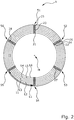
- Figure 2 shows a stator 1 with slots and pins on six layers, only six slots 51-56 being shown.
- Pins 21-28 are arranged in the grooves by way of example.
- the pins are next to each other in a groove.
- the six pins within a slot are therefore on different concentric circles L1, L2, L3, L4, L5, L6 around the center point M of the stator, which thus form individual layers.
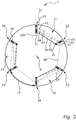
- Figure 3 shows the stator 1 from Figure 2 .
- the pins are still arranged on concentric circles, i.e. layers, whereby the concentric circles are not shown for better illustration.
- Figure 3 shows which pins are connected to each other in series.
- a first pin 21 is located in a first groove 51 in layer L5.
- This first pin 21 is connected to a second pin 22 in a second groove 52 by means of a first type of connection 61, shown as a solid line.
- the second pin 22 is located in layer L6. Between the first groove 51 and the second groove 52 there is a first distance 11 of the same length as the first distance 11 Figure 2 is.
- the second pin 22 is connected to a third pin 23 in the first groove 51 by means of a second type of connection 62, shown as a dashed line.
- the third pin 23 is in layer L4 and in the same groove as the first pin 21.
- the third pin 23 is connected to a fourth pin 24 via a third type of connection 63, shown as a dotted line with very short distances.
- the fourth pin 24 lies in the second groove 52 in the same groove as the second pin 22.
- the fourth pin 24 lies in the layer L3.
- the fourth pin 24 is connected to a fifth pin 25 in the first groove 51 by means of a fourth type of connection 64, shown as a dashed line with long distances.
- the fifth pin 25 is in turn located in the first groove 51, that is to say in the same groove as the first pin 21 and the third pin 23.
- the fifth pin 25 is in the layer L1. Between the third pin 23 and the fifth pin 25 in the first groove 51 there is still space for two further pins in layers L2 and L3. In addition, there is still space in the first groove 51 for a further pin in layer L6.
- the fifth pin 25 is connected to a sixth pin 26 via a fifth type of connection 65, shown as a dotted line with long distances.
- the sixth pin 26 lies in the second groove 52, that is to say the same groove as the second pin 22 and fourth pin 24.
- the sixth pin 26 lies in the layer L2.
- the connection of the first, second, third, fourth, fifth and sixth pins forms a first turn 41.
- the first pin 21 is at the same time also a first end pin.
- This end pin 21 has an input 101 for connecting an energy source, for example an inverter.
- the first end pin 21 is therefore only connected to one further pin, that is to say the second pin 22.
- the first end pin 21 can thus be designed as a so-called single pin or Ipin.
- the sixth pin 26 is connected to a seventh pin 27 in layer L5 in a third groove 53 via a sixth type of connection 66, shown as a dotted line with short distances.
- the previously described serial connection of the subsequent pins in the stator begins again with the seventh pin 27, the seventh pin 27 being similar to the first pin 21 with an offset of the slot by 120 degrees.
- the seventh pin 27 is not an end pin because the seventh pin 27 is connected to two further pins, i.e. the sixth pin 26 and another pin in groove 54, layer L1.
- the serial connection of the seventh pin 27 with further pins in the groove 54 forms a second turn 42.
- the first, second, third, fourth and fifth type of connection 61 - 65 between these pins is identical to the respective first, second, third, fourth, fifth type of connection 61 - 65 of the pins of the first turn 41.
- the two turns 41, 42 are connected by the sixth type of connection 66.
- the third turn 43 is formed in two further grooves 55 and 56.
- the turns 41, 42, 43 are each connected to the sixth type of connection 66.
- the sixth type of connection 66 between the respective turns is thus identical.
- the first, second, third, fourth and fifth type of connection 61-65 between the pins of the third turn 43 is also identical to the first, second, third, fourth and fifth type of connection 61-65 of the first and second turns 41, 42.
- the fourth turn 44 is formed in two further grooves 57 and 58.
- the turns 41, 42, 43, 44 are each connected to the sixth type of connection 66.
- the sixth type of connection 66 between the respective turns is thus identical.
- the first, second, third, fourth and fifth type of connection 61 - 65 between the pins of the fourth turn 44 is identical to the first, second, third, fourth and fifth type of connection 61 - 65 of the first, second and third turns 41, 42, 43.
- the four turns 41, 42, 43, 44 form a first partial coil by rotating around the stator 1 in a clockwise direction.
- the first pin 21 also has an input 101 for connecting an energy source.
- the first pin 21 of the turn 41 thus represents a first end pin.
- the coil section ends with the pin 28 of the third turn 43.
- the last pin 28 of the third turn 43 thus represents a second end pin End pin 21, however, has connections to two other pins, as in connection with Figure 6 explained.
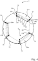
- Figure 4 shows the stator 1 from Figure 3 , six further grooves 71-76 being shown there, which are in the direct vicinity of the grooves 51-56 Figure 3 are located.
- the distance 11 have the same length as in Figure 3 on.
- the pins 21a-28a are in the same way as the pins 21-28 of the Figure 3 connected. Even the connection type is identical to the Figure 3 and made clear by the same reference numerals. In the same way as with Figure 3 described, the turns 41a, 42a, 43a are formed and are connected to each other by the sixth type of connection 66 in the clockwise direction.
- the three turns 41a, 42a, 43a form a second partial coil by rotating around the stator 1.
- the coil section begins with a pin 21a, which is a third end pin.
- the third end pin 21a has connections to two further pins, as in connection with FIG Figure 6 explained.
- the coil section ends with pin 28a of turn 43a.
- the last pin 28a of the turn 43a thus represents a fourth end pin 28a.
- Figure 5 shows the stator 1 from Figure 3 and 4th , six further grooves 81-86 are shown there, which are in the direct vicinity of the grooves 71-76 Figure 4 are located.
- the distance 11 have the same length as in Figure 3 on.
- the pins 21b-28b are in the same way as the pins 21-28 of the Figure 3 and pins 21a - 28a of the Figure 4 connected. Even the type of connection is identical to the Figures 3 and 4th and made clear by the same reference numerals. In the same way as with Figure 3 and 4th described, the turns 41b, 42b, 43b are formed and are connected to each other by the sixth type of connection 66 in the clockwise direction.
- the three turns 41b, 42b, 43b form a third partial coil by rotating around the stator 1.
- the coil section begins with a pin 21b, which is a fifth end pin.
- the fifth end pin 21b has connections to two further pins, as in connection with FIG Figure 6 explained.
- the coil section ends with pin 28b of turn 43b.
- the last pin 28b of the turn 43b thus represents a sixth end pin.
- the sixth end pin 28b in turn is designed similar to the first end pin 21, for example as a single pin or Ipin and has an output 103 for connecting an energy source.
- Figure 6 shows a pin assignment through the first, second and third sub-coil Figure 3 , 4th and 5 , which are represented by black squares.
- the same reference symbols denote the same pins, grooves and connections in the figures.
- the second end pin 28 of the third turn 43 of the first coil section in slot 56, layer L2 and the third end pin 21a of the first turn 41a of the second coil section in slot 71, layer L5 is connected to a seventh type of connection 67.
- the seventh type of connection overcomes a second distance 13 which is one groove shorter than the first distance 11.
- the fourth End pin 28a of turn 43a of the second coil section in slot 76, layer L5 and the fifth end pin 21b of first turn 41b of the third coil section in slot 81, layer L2 is connected to a seventh type of connection 67.
- the seventh type of connection overcomes the second distance 13.
- connection 67 thus connects two sub-coils in each case, with three sub-coils forming a first coil 201 with an input 101 and an output 103 after three radial rotation around the stator in a clockwise direction.
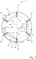
- Figure 7 shows the stator 1 from Figure 2 .
- the pins are still arranged on concentric circles, i.e. layers, whereby the concentric circles are not shown for better illustration. It is shown which pins, shown as black squares on a white background, are connected to one another in series and form a first partial coil of a second coil 202.
- a first pin 31 is located in the first groove 51 in layer L6.
- the first pin 31 is at the same time also a seventh end pin 31.
- This end pin 31 has an input 105 for connecting an energy source, for example an inverter.
- the seventh end pin 31 is therefore only connected to one further pin, that is to say a ninth pin 39.
- the seventh end pin 31 can thus be designed as a so-called single pin or Ipin.
- the first pin 31, or seventh end pin is connected to a ninth pin 39 in a groove 56 by means of the first type of connection 61, shown as a solid line.
- the ninth pin 39 is in layer L5. Between the first groove 51 and the groove 56 there is a first distance 11 which is the same length as the first distance 11 Figure 2 is.
- the ninth pin 39 is shown by means of a sixth connection type 66, as a dotted line with short distances, connected to a sixth pin 36 in a groove 55.
- the sixth pin 36 is in layer L2.
- the sixth pin 36 is connected to a fifth pin 35 in groove 54 via a fifth type of connection 65, shown as a dotted line with long distances.
- the fifth pin 35 is in layer L1.
- the fifth pin 35 is connected to a fourth pin 34 in the groove 55 by means of the fourth type of connection 64, shown as a dashed line with long distances.
- the fourth pin 34 is connected to a third pin 33 via the third type of connection 63, shown as a dotted line with very short distances.
- the third pin 33 is in the groove 54.
- the third pin 33 is in the layer L4.
- the third pin 33 is connected to a second pin 32 in the groove 55 via the second type of connection 62, shown as a dashed line.
- the second pin 32 is in layer L6.
- the second pin 32 lies in the groove 55, that is to say the same groove as the fourth pin 34 and sixth pin 36.
- the second pin 32 lies in the layer L6.
- the second pin 32 is connected to a seventh pin 37 in the groove 54 via the first type of connection 61, shown as a solid line.
- the seventh pin 37 is in layer L5.
- the seventh pin 37 is in the groove 54, that is, in the same groove as the third pin 33 and fifth pin 35. Between the fifth pin 35 and the third pin 33 in the groove 54 there is still space for two more pins in layers L2 and L3. In addition, there is still space in the groove 54 for another pin in layer L6.
- connection of the second, third, fourth, fifth, sixth and seventh pins 32 - 37 forms a fourth turn 44.
- the seventh pin 37 is connected to a tenth pin 36 (2) via the sixth connection type 66, shown as a dotted line with short distances.
- the tenth pin 36 (2) is in the third groove 53 in layer L2.
- the previously described serial connection of the subsequent pins in the stator begins again with the tenth pin 36 (2), the tenth pin 36 (2) being similar to the sixth pin 36 with an offset of the slot by 120 degrees.
- the serial connection of the tenth pin 36 (2) with further pins in the second groove 52 forms a fifth turn 45.
- the first, second, third, fourth and fifth type of connection 61 - 65 between these pins is identical to the respective first, second, third, fourth and fifth type of connection 61-65 of the pins of the first to fourth turns 41-44.
- the two turns 44, 45 are connected by the sixth type of connection 66.
- the sixth turn 46 is completed in two further grooves 51 and 56.
- the turns 44 - 46 are each connected to the sixth type of connection 66.
- the sixth type of connection 66 between the respective turns is thus identical.
- the first, third, fourth and fifth type of connection 61, 63 - 65 between the pins of the sixth turn 46 is identical to the first, third, fourth and fifth type of connection 61, 63 - 65 of the previous turns 41 - 45.
- the sixth turn 46 is completed by a connection of an eighth type of connection 68. This connection is in Figure 10 and is described in conjunction with this figure.
- the four turns 45-48 form a first partial coil by rotating around the stator 1 in a counterclockwise direction.
- the first coil section of the second coil 202 ends with an eighth end pin 38.
- Figure 8 shows the stator 1 from Figure 7 , six further grooves 71-76 being shown there, which are in the direct vicinity of the grooves 51-56 Figure 7 are located.
- the distance 11 has the same length as in the previous figures.
- the pins 31a - 39a are in the same way as the pins 31 - 39 of the Figure 7 connected. Even the type of connection is identical to the previous figures and made clear by the same reference symbols. In the same way as with Figure 7 described, the turns 44a, 45a, 46a are formed and are connected to each other by the sixth type of connection 66 in the clockwise direction.
- the three turns 44a, 45a, 46a form a second partial coil by rotating around the stator 1 in a counterclockwise direction.
- the coil section begins with a pin 31a, which is a ninth end pin.
- the ninth end pin 31a has connections to two further pins, as in connection with FIG Figure 10 explained.
- the coil section ends with pin 38a of turn 46a.
- the pin 38a of the turn 46a thus represents a tenth end pin 38a.
- the turn 46a also has two end pins 31a, 38a.
- Figure 9 shows the stator 1 from Figure 7 and 8th , six further grooves 81-86 are shown there, which are in the direct vicinity of the grooves 71-76 Figure 8 are located.
- the distance 11 has the same lengths as in the previous figures.
- the pins 31b - 39b are in the same way as the pins 31 - 39 of the Figure 7 and pins 31a - 39a of the Figure 8 connected. Even the type of connection is identical to the previous figures and made clear by the same reference symbols.
- the turns 44b, 45b, 46b are formed and are connected to one another by the sixth type of connection 66 in a counterclockwise direction.
- the three turns 44b, 45b, 46b form a third partial coil by rotating around the stator 1.
- the sub-coil begins with a pin 31b, which is an eleventh end pin.
- the eleventh end pin 31b has connections to two further pins, as in connection with FIG Figure 10 explained.
- the coil section ends with pin 38b of turn 46b.
- the pin 38b of the turn 46b thus represents a twelfth end pin.
- the twelfth end pin 38b in turn is designed similar to the seventh end pin, for example as a single pin or Ipin, and has an output 107 for connecting an energy source.
- FIG. 12 shows a pin assignment through the first, second and third coil sections of the second coil 202 Figure 7 , 8th and 9 , which are represented by black squares on a white background.
- the same reference symbols denote the same pins, grooves and connections in the figures.
- the eighth end pin 38 of the turn 46 of the first coil section in slot 56, layer L3, and the ninth end pin 31a of the turn 46a of the second coil section in slot 71, layer L1, are connected to an eighth type of connection 68.
- the eighth type of connection overcomes a second distance 13 which is one groove shorter than the first distance.
- the tenth end pin 38a of turn 46a of the second sub-coil in slot 76, layer L3 and the eleventh End pin 31b of turn 46b of the third sub-coil in slot 81, layer L1 is connected to the eighth type of connection 68.
- connection 68 thus connects two sub-coils, with three sub-coils forming the second coil 202 with an input 105 and an output 107 after three radial rotation around the stator in the counterclockwise direction.
- a third distance 15 shown in the figure is two grooves shorter than the first distance 11 from the previous figure.
- Figure 11 shows the first coil 201 and the second coil 202 from the previous figures in a stator 1.
- the same reference symbols from the previous figures denote the same pins, slots and connection types.
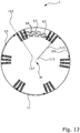
- Figure 12 shows two further coils, each formed by pins with a black point and a white point.
- the three sub-coils of the coil with the pins with white dot are according to the description of the Figures 3 - 6 formed with the grooves offset 20 degrees clockwise.
- the three sub-coils of the coil with the pins with black dot are according to the Figures 7-10 formed with the grooves twisted 20 degrees clockwise.
- Figure 13 shows two further coils, each formed by pins with a black cross and a white cross.
- the three sub-coils of the coil with the pins with a white cross are according to the description of the Figures 3 - 6 formed with the grooves offset 40 degrees clockwise.
- the three sub-coils of the coil with the pins with black cross are according to the Figures 7 - 10 formed with the grooves offset 40 degrees clockwise.
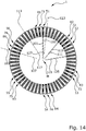
- Figure 14 shows a pinout through the six coils as a combination of the Figures 11 , 12th and 13th .
- the coils can be interconnected within twenty-four slots.
- the inputs and outputs can thus be interconnected within almost half of the stator circumference. In relation to the inputs or outputs, separate wiring within thirteen slots would be possible.
- Figure 15 shows the winding diagram of the three sub-coils of the first coil 201.
- the consecutive "slot number" is not a reference symbol.
- the reference symbols with arrows on the grooves are identical to the previous figures and enable comparison with these figures.
- Figure 16 shows the winding diagram of the three sub-coils of the second coil 202.
- the consecutive "slot number" is not a reference symbol.
- the reference symbols with arrows on the grooves are identical to the previous figures and enable comparison with these figures.
- Figure 17 shows a first single pin 211 or also called Ipin on the left.
- the first end pin 21 which is arranged, for example, in the first slot 51, layer L5, of the stator.
- the reference symbols are identical to the previous figures.
- the first individual pin 211 is shown from the perspective of the stator center point with the first end face 7 facing up.
- the first single pin is at the lower end 211 a pin foot 61a with a first weld point 231. At the upper end is the entrance 101, 111, 121.
- a second single pin 212 is shown.
- the sixth end pin 28b which is arranged, for example, in the slot 86, layer L2, of the stator.
- the reference symbols are identical to the previous figures.
- the pins are shown from the perspective of the stator center point with the first end face 7 facing up.
- the second individual pin 212 has a pin foot 65b with a sixth weld point 236.
- the exit 103, 113, 123 At the upper end there is the exit 103, 113, 123.
- Figure 18 shows a third single pin 213 or also called Ipin on the left.
- the seventh end pin 31 which is arranged, for example, in the first slot 51, layer L6, of the stator.
- the reference symbols are identical to the previous figures.
- the single pin 213 is shown from the perspective of the stator center point with the first end face 7 facing up.
- the third individual pin 213 has a pin foot 61b with a second weld point 232.
- the entrance 105, 115, 125 is the entrance 105, 115, 125.
- a fourth single pin 214 is shown.
- the twelfth end pin 38b which is arranged, for example, in the slot 86, layer L4, of the stator.
- the reference symbols are identical to the previous figures.
- the pins are shown from the perspective of the stator center point with the first end face 7 facing up.
- the fourth individual pin 214 has a pin foot 63a with a third weld point 233.
- Figure 19 shows a first double pin 215 or Upin, the second type of connection 62 between a second pin 22, 22a, 22b, 32, 32a, 32b and a third pin 23, 23a, 23b, 33, 33a, 33b.
- the double pin 215 can bridge the first distance 11 between the grooves.
- the double pin has two inwardly bent pin feet 63a, 61b with a third welding point 233 and a second welding point 232.
- Figure 20 shows a second double pin 216 or Upin, which establishes the fourth type of connection 64 between a fifth pin 25, 25a, 25b, 35, 35a, 35b and a fourth pin 24, 24a, 24b, 34, 34a, 34b.
- the double pin 216 can bridge the first distance 11 between the grooves.
- the double pin has two inwardly bent pin feet 65a, 63b with a fifth weld point 235 and a fourth weld point 234.
- Figure 21 shows a third double pin 217 or Upin, the sixth connection type 66 between a sixth pin 26, 26a, 26b, 36, 36a, 36b, 36 (2), 36a (2), 36b (2) and a seventh or ninth pin 27 , 27a, 27b, 37, 37a, 37b, 39, 39a, 39b.
- the third double pin 217 can bridge the first distance 11 between the grooves.
- the double pin has two outwardly bent pin feet 65b, 61a with a sixth weld point 236 and a first weld point 231.
- the first distance 11 is only identical with regard to the number of grooves to be bridged.
- the actual spatial distance to be bridged differs because the double pins connect different layers.
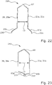
- Figure 22 shows a fourth double pin 218 or Upin, which produces the seventh type of connection 67 between a second or fourth end pin 28, 28a and a third or fifth end pin 21a, 21b.
- the fourth double pin 218 can have the second distance 13 so by one groove less than the first distance 11 is bridged.
- the fourth double pin 218 has two outwardly bent pin feet 65b, 61a with a sixth weld point 236 and a first weld point 231.
- Figure 23 shows a fifth double pin 219 or Upin, which produces the eighth type of connection 68 between an eighth or tenth end pin 38, 38a and a ninth or eleventh end pin 31a, 31b.
- the fifth double pin 219 can bridge the second distance 13 by one groove less than the first distance 11 is.
- the fifth double pin 219 has two inwardly bent pin feet 63a, 61b with a third welding point 233 and a second welding point 232.
- the various single and double pins in the Figures 17 to 23 have similar pin feet.
- the first type of connection 61 is formed by welding the first weld point 231 on the pin foot 61a to the second weld point 232 on the pin foot 61b in accordance with the winding diagram.
- the third type of connection 63 is formed by welding the third weld point 233 on the pin foot 63a to the fourth weld point 234 on the pin foot 63b in accordance with the winding diagram.
- the fifth type of connection 65 is formed by welding the fifth spot weld 235 on the pin foot 65a to the sixth spot weld 236 on the pin foot 65b according to the winding scheme.
- FIG. 24 is a schematic diagram of an exemplary embodiment of a vehicle 403, for example a hybrid vehicle or an electric vehicle, comprising an electric machine 401, in particular an electric motor, with a Embodiment of the stator 1 for driving the vehicle 403.
- the vehicle 403 can have an inverter 405 which supplies the electrical machine 401 with an alternating current from a direct current source.
Landscapes
- Engineering & Computer Science (AREA)
- Power Engineering (AREA)
- Manufacturing & Machinery (AREA)
- Windings For Motors And Generators (AREA)
Abstract
Description
- Die Erfindung betrifft einen Stator mit versetzten Pins für eine elektrische Maschine, insbesondere einen Elektromotor.
- Elektrische Maschinen sind allgemein bekannt und finden als Elektromotor zunehmend Anwendung für den Antrieb von Fahrzeugen. Eine elektrische Maschine besteht aus einem Stator und einem Rotor.
- Der Stator umfasst eine Vielzahl von Nuten, in welchen die Windungen geführt werden. Die Windungen können aus isolierten Kupferstäben, als sogenannte Pins, gebildet werden. Der Rotor befindet sich im Stator und ist mit einer Rotorwelle verbunden.
- Ein solcher Pin-, UPin- oder Hairpinmotor ist beispielsweise aus
US 9,136,738 B2 - Aufgabe der vorliegenden Erfindung ist es, einen Stator mit Windungen aus Pins bereitzustellen, welcher einfach zu fertigen ist.
- Erfindungsgemäß umfasst ein Stator für eine elektrische Maschine eine Vielzahl von Pins, die auf konzentrischen Kreisen mit unterschiedlichen Abständen zu einem Statormittelpunkt in Nuten im Stator angeordnet sind und jeder konzentrische Kreis einen Layer bildet, wobei jeweils sechs Pins in unterschiedlichen Layer miteinander seriell verbunden sind und eine Windung bilden, ein erster Pin der Windung befindet sich in einer ersten Nut im 6n-1 Layer, wobei n eine natürliche Zahl ist, ein zweiter Pin der Windung befindet sich in einer zweiten Nut im 6n Layer, wobei die zweite Nut einen ersten radialen Abstand in einer ersten Umfangsrichtung des Stators zu der ersten Nut aufweist, ein dritter Pin der Windung befindet sich in der ersten Nut im 6n-2 Layer, ein vierter Pin der Windung befindet sich in der zweiten Nut im 6n-3 Layer, ein fünfter Pin befindet sich in der ersten Nut im 6n-5 Layer, ein sechster Pin der Windung befindet sich in der zweiten Nut im 6n-4 Layer.
- Dabei kann eine Windung die Zähne auch mehrfach umlaufen. Die Layer können von außen nach innen zum Statormittelpunkt aufsteigend nummeriert werden. Die Zahl Null gehört nicht zu den erwähnten natürlichen Zahlen.
- Ein Stator mit der erfindungsgemäßen Wicklung lässt sich einfach herstellen und erzeugt ein effizientes elektromagnetisches Feld. Die Verbindungsarten stellen eine elektrisch leitfähige Verbindung zwischen den Pins in den Nuten her. Die Verbindungsart kann ein Anschweißen von Leitern an die Pins sein oder die Pins können bereits als Doppelpin, sogenannte Upins, ausgebildet sein und dadurch bereits beim Einführen in den Stator eine Verbindung herstellen. Ferner stellt auch ein Verschweißen von zueinander gebogenen Endabschnitten von Pins eine Verbindungsart dar.
- Bevorzugt kann der Stator eine erste Stirnseite und eine zweite Stirnseite aufweisen und der erste Pin und der zweite Pin auf der zweiten Stirnseite mittels einer ersten Verbindungsart miteinander verbunden sein, der zweite Pin und der dritte Pin auf der ersten Stirnseite mittels einer zweiten Verbindungsart miteinander verbunden sein, der dritte Pin und der vierte Pin auf der zweiten Stirnseite mittels einer dritten Verbindungsart miteinander verbunden sein, der vierte Pin und fünfte Pin auf der ersten Stirnseite mittels einer vierten Verbindungsart miteinander verbunden sein, der fünfte Pin und der sechste Pin auf der zweiten Stirnseite mittels einer fünften Verbindungsart miteinander verbunden sein, wobei sich die erste, zweite, dritte, vierte und fünfte Verbindungsart voneinander unterscheiden.
- Die unterschiedlichen Verbindungsarten ermöglichen eine verbesserte Fertigung. Eine abwechselnde Lage der Verbindungsarten auf verschiedenen Stirnseiten ermöglicht das effiziente Bilden einer Windung um die zwischen den Nuten liegenden Statorzähne.
- Selbst Verbindungsarten auf derselben Stirnseite des Stators können sich durch unterschiedliche Biegerichtungen eines Pinfußes zum Stator inneren oder -äußeren unterscheiden.
- Weiter bevorzugt kann der Stator zumindest zwei Windungen aufweisen und zumindest der sechste Pin in der zweiten Nut mit einem siebten Pin im 6n-1 Layer in einer dritten Nut mittels einer sechsten Verbindungsart verbunden sein.
- Eine Kombination der vorher genannten Verbindungsarten auf unterschiedlichen oder gleichen Stirnseiten des Stators ist auch möglich. Durch eine gleiche Verbindungsart auf gleichen Stirnseiten und verschiedenen Verbindungsarten auf unterschiedlichen Stirnseiten des Stators ist eine einfache und schnelle Fertigung möglich. Beispielsweise wird auf einer Stirnseite die Verbindung durch eine Art vorgebogene Pins, sogenannte Doppelpins oder auch Upins genannt, hergestellt und auf einer anderen Stirnseite des Stators werden Pins einzeln oder jeweils eine Seite des Doppelpins miteinander verschweißt. Die Schweißpunkte können an Füßen der Pins oder Doppelpins liegen.
- Bevorzugt kann der Pin am Anfang einer Windung ein Endpin sein, wobei der erste Endpin als Einzelpin ausgestaltet ist. Ein Einzelpin ist beispielsweise ein IPin.
- In einer Ausgestaltung der Erfindung kann zwischen der dritten Nut und der zweiten Nut der gleiche erste Abstand wie zwischen der zweiten Nut und der ersten Nut liegen.
- Weiter bevorzugt kann der Stator eine Vielzahl von Windungen aufweisen, die sich über den gesamten Umfang des Stators erstrecken und dabei eine Teilspule bilden.
- Das mit einer solchen Windung erzeugte Drehfeld weist weniger störende Harmonische auf und hat dadurch weniger Torqueripple und kleinere Drehmomentschwankungen sowie ein besseres NVH Verhalten. Die Wicklungen weisen eine Symmetrie auf, welche ein gleichmäßiges Drehfeld erzeugt.
- In einer Ausgestaltung der Erfindung können die Endpins am Anfang oder Ende einer Spule als Einzelpins ausgestaltet sein. Ein Einzelpin ist beispielsweise ein IPin.
- In einer weiteren Ausgestaltung kann je ein Pin von drei Teilspulen mittels einer siebten Verbindungsart oder einer achten Verbindungsart miteinander verbunden sein und eine Spule (201, 202) bilden. Bei diesen Pins kann es sich um sogenannte Endpins handeln, da sie das Ende einer Teilspule markieren.
- Bevorzugt können die Teilspulen sechs Spulen bilden und diesen derart drei Phasen zugeordnet sein, dass sich jeweils die Pins von zwei Spulen, die einer gleichen Phase zugeordnet sind, in drei benachbarten Nuten befinden.
- Weiter bevorzugt kann je ein Eingang eines Endpins von zwei Spulen mittels einer neunten Verbindungsart miteinander verbunden sein.
- Bevorzugt kann je ein Ausgang eines Endpins der zwei Spulen miteinander verbunden sein und die zwei Spulen dadurch parallelgeschaltet und insbesondere einer Phase zugeordnet sein.
- Die neunte Verbindungsart kann durch einen an den Pins angebrachten Leiter oder durch einen leitenden Ring hergestellt werden.
- Die beiden Spulen können parallel verbunden sein und können zusätzlich von einer gleichen Phase gespeist werden. Die Parallelverbindung kann durch das paarweise Verbinden von einem ersten und siebten oder sechsten und zwölften Endpin erfolgen.
- Zwei Spulen in gleichen Nuten können parallelgeschaltet und von einer Phase gespeist werden, sodass ein Stator mit Windungen für eine dreiphasige elektrische Maschine ausgebildet wird.
- Ferner können jeweils zwei Phasen einen annährend identischen Strom- und Spannungsverlauf aufweisen und dadurch ein sechs Phaseninverter lediglich einen dreiphasigen Motor ansteuern. Mit dieser Anordnung ist eine Stromteilung der Schaltelemente im Inverter möglich.
- Bevorzugt kann die zweite Verbindungsart einen ersten Doppelpin umfassen, der aus dem zweiten Pin und dem dritten Pin gebildet wird, wobei der erste Doppelpin zwei nach innen gebogene Pinfüße mit je einem Schweißpunkt aufweist und den ersten radialen Abstand überbrückt.
- Der Doppelpin kann aus einem Stab bestehen, der derart gebogen wird, sodass zwei Pins, eine Verbindung zwischen diesen zwei Pins an einem ersten Ende und Pinfüße an einem zweiten Ende entstehen.
- Der Doppelpin kann von einer Stirnseite in den Stator eingeführt und auf der anderen Stirnseite an Pinfüßen eines weiteren Doppelpin verschweißt werden.
- Der erste Abstand beschreibt eine zu überbrückende Nutanzahl. Der tatsächlich zu überbrückende räumliche Abstand hängt von der Lage des Pins im Layer ab, weil die Doppelpins unterschiedliche Layer verbinden.
- Weiter bevorzugt kann die vierte Verbindungsart einen zweiten Doppelpin umfassen, der aus dem vierten Pin und dem fünften Pin gebildet wird, wobei der zweite Doppelpin zwei nach innen gebogene Pinfüße mit je einem Schweißpunkt aufweist und den ersten radialen Abstand überbrückt.
- In einer Ausgestaltung der Erfindung kann die sechste Verbindungsart einen dritten Doppelpin umfassen, der aus dem sechsten Pin und dem siebten oder neunten Pin gebildet wird, wobei der dritte Doppelpin zwei nach außen gebogene Pinfüße mit je einem Schweißpunkt aufweist und den ersten radialen Abstand überbrückt.
- Bevorzugt kann die siebte Verbindungsart einen vierten Doppelpin umfassen, der aus einem zweiten oder vierten Endpin und einem dritten oder fünften Endpin gebildet wird, wobei der vierte Doppelpin zwei nach außen gebogene Pinfüße mit je einem Schweißpunkt aufweist und einen zweiten radialen Abstand überbrückt.
- Weiter bevorzugt kann die achte Verbindungsart einen fünften Doppelpin umfassen, der aus einem achten oder zehnten Endpin und einem neunten oder elften Endpin gebildet wird, wobei der fünfte Doppelpin zwei nach innen gebogene Pinfüße mit je einem Schweißpunkt aufweist und einen zweiten radialen Abstand überbrückt.
- In einer Ausgestaltung der Erfindung kann ein erster Einzelpin einen ersten Endpin umfassen und einen im Uhrzeigersinn gebogenen Pinfuß mit einem Schweißpunkt aufweisen.
- In einer weiteren bevorzugten Ausgestaltung der Erfindung kann ein zweiter Einzelpin einen sechsten Endpin umfassen und einen gegen den Uhrzeigersinn gebogenen Pinfuß mit einem Schweißpunkt aufweisen.
- Bevorzugt kann ein dritter Einzelpin einen siebten Endpin umfassen und einen gegen den Uhrzeigersinn gebogenen Pinfuß mit einem Schweißpunkt aufweisen.
- Weiter bevorzugt kann ein vierter Einzelpin einen zwölften Endpin umfassen und einen im Uhrzeigersinn gebogenen Pinfuß mit einem Schweißpunkt aufweisen.
- In einer Ausgestaltung kann die erste Verbindungsart durch eine Schweißverbindung eines ersten Schweißpunkts am Pinfuß des dritten Doppelpins oder des vierten Doppelpins oder des ersten Einzelpins mit einem zweiten Schweißpunkt am Pinfuß des ersten Doppelpins oder des fünften Doppelpins oder des dritten Einzelpins gebildet werden.
- Bevorzugt kann die dritte Verbindungsart durch eine Schweißverbindung eines dritten Schweißpunkts am Pinfuß des ersten Doppelpins oder des fünften Doppelpins mit einem vierten Schweißpunkt am Pinfuß des zweiten Doppelpins gebildet werden.
- Weiter bevorzugt kann die fünfte Verbindungsart durch eine Schweißverbindung eines fünften Schweißpunkts am Pinfuß des zweiten Doppelpins mit einem sechsten Schweißpunkt am Pinfuß des dritten Doppelpins oder des vierten Doppelpins oder des zweiten Einzelpins gebildet werden.
- Erfindungsgemäß weist ein Fahrzeug eine elektrische Maschine mit einem Stator gemäß einer der bevorzugten Ausgestaltungen auf.
-
-
Figur 1 zeigt einen Stator. -
Figur 2 zeigt einen Stator mit sechs Nuten und sechs Layer. -
Figur 3 zeigt ein Wickelschema einer ersten Teilspule. -
Figur 4 zeigt ein Wickelschema einer zweiten Teilspule. -
Figur 5 zeigt ein Wickelschema einer dritten Teilspule. -
Figur 6 zeigt einen Stator mit drei Teilspulen und deren Verbindung miteinander und somit eine erste Spule. -
Figur 7 zeigt ein Wickelschema einer weiteren ersten Teilspule. -
Figur 8 zeigt ein Wickelschema einer weiteren zweiten Teilspule. -
Figur 9 zeigt ein Wickelschema einer weiteren dritten Teilspule. -
Figur 10 zeigt einen Stator mit drei weiteren Teilspulen und deren Verbindung miteinander und somit eine zweite Spule. -
Figur 11 zeigt einen Stator mit zwei Spulen, bestehend aus jeweils drei Teilspulen. -
Figur 12 zeigt einen Stator mit zwei weiteren Spulen. -
Figur 13 zeigt einen Stator mit zwei weiteren Spulen. -
Figur 14 zeigt einen Stator mit sechs Spulen. -
Figur 15 zeigt ein Windungsschema einer ersten Spule. -
Figur 16 zeigt ein Windungsschema einer zweiten Spule. -
Figur 17 zeigt zwei Einzelpins. -
Figur 18 zeigt zwei Einzelpins. -
Figur 19 einen ersten Doppelpin. -
Figur 20 einen zweiten Doppelpin. -
Figur 21 einen dritten Doppelpin. -
Figur 22 einen vierten Doppelpin. -
Figur 23 einen fünften Doppelpin. -
Figur 24 zeigt ein Fahrzeug mit einer elektrischen Maschine insbesondere einem Elektromotor mit einem Stator. -
Figur 1 zeigt einen Stator 1 mit einer Vielzahl an Nuten 5 in welchen Pins 2, 3 geführt werden. Der Stator 1 weist eine erste Stirnseite 7 und eine gegenüberliegende zweite Stirnseite 9 auf. Selbstverständlich ist zum Betrieb einer elektrischen Maschine ferner ein Rotor nötig. -
Figur 2 zeigt einen Stator 1 mit Nuten und Pins auf sechs Layer, wobei lediglich sechs Nuten 51 - 56 dargestellt sind. In den Nuten sind exemplarisch Pins 21 - 28 angeordnet. Die Pins liegen nebeneinander in einer Nut. Im Beispiel derFigur 2 ist für sechs nebeneinanderliegenden Pins Platz in einer Nut. Die sechs Pins innerhalb einer Nut liegen somit auf unterschiedlichen konzentrischen Kreisen L1, L2, L3, L4, L5, L6 um den Mittelpunkt M des Stators, die somit einzelne Layer bilden. Zwischen jeweils zwei Nuten liegt ein erster Abstand 11, welcher zwischen allen inFigur 2 gezeigten Nuten identisch ist. -
Figur 3 zeigt den Stator 1 ausFigur 2 . Die Pins sind weiterhin auf konzentrischen Kreisen, also Layer, angeordnet, wobei die konzentrischen Kreise wegen einer besseren Darstellung nicht eingezeichnet sind. InFigur 3 ist dargestellt, welche Pins miteinander in Serie verbunden sind. Ein erster Pin 21 befindet sich in einer ersten Nut 51 im Layer L5. Dieser erste Pin 21 ist mittels einer ersten Verbindungsart 61, als durchgezogene Linie dargestellt, mit einem zweiten Pin 22 in einer zweiten Nut 52 verbunden. Der zweite Pin 22 befindet sich im Layer L6. Zwischen der ersten Nut 51 und der zweiten Nut 52 liegt ein erster Abstand 11 der gleichlang wie der erste Abstand 11 ausFigur 2 ist. - Der zweite Pin 22 ist mittels einer zweiten Verbindungsart 62, als gestrichelte Linie dargestellt, mit einem dritten Pin 23 in der ersten Nut 51 verbunden. Der dritte Pin 23 liegt im Layer L4 und in derselben Nut wie der erste Pin 21. Der dritte Pin 23 ist über eine dritte Verbindungsart 63, als gepunktete Linie mit sehr kurzen Abständen dargestellt, mit einem vierten Pin 24 verbunden. Der vierte Pin 24 liegt in der zweiten Nut 52 also in derselben Nut wie der zweite Pin 22. Der vierte Pin 24 liegt im Layer L3.
- Der vierte Pin 24 ist mittels einer vierten Verbindungsart 64, als gestrichelte Linie mit langen Abständen dargestellt, mit einem fünften Pin 25 in der ersten Nut 51 verbunden. Der fünfte Pin 25 befindet sich wiederum in der ersten Nut 51, also in derselben Nut wie der erste Pin 21 und der dritte Pin 23. Der fünfte Pin 25 liegt im Layer L1. Zwischen dem dritten Pin 23 und dem fünften Pin 25 in der ersten Nut 51 ist noch Platz für zwei weiteren Pins in Layer L2 und L3. Außerdem ist in der ersten Nut 51 noch Platz für einen weiteren Pin in Layer L6. Der fünfte Pin 25 ist über eine fünfte Verbindungsart 65, als gepunktete Linie mit langen Abständen dargestellt, mit einem sechsten Pin 26 verbunden. Der sechste Pin 26 liegt in der zweiten Nut 52, also derselben Nut wie der zweite Pin 22 und vierte Pin 24. Der sechste Pin 26 liegt im Layer L2. Zwischen dem zweiten Pin 22 und dem vierten Pin 24 ist noch Platz in der zweiten Nut 52 für zwei weitere Pins in den Layer L4 und L5. Außerdem ist in der zweiten Nut 52 noch Platz für einen weiteren Pin in Layer L1.
- Die Verbindung des ersten, zweiten, dritten, vierten, fünften und sechsten Pins bildet eine erste Windung 41. Der erste Pin 21 ist gleichzeitig auch ein erster Endpin. Dieser Endpin 21 weist einen Eingang 101 zum Anschluss einer Energiequelle, beispielsweise eines Inverters, auf. Der erste Endpin 21 ist daher nur mit einem weiteren Pin, also dem zweiten Pin 22, verbunden. Der erste Endpin 21 kann somit als sogenannter Einzelpin oder Ipin ausgestaltet sein.
- Der sechste Pin 26 ist über eine sechste Verbindungsart 66, als gepunktete Linie mit kurzen Abständen dargestellt, mit einem siebten Pin 27 in Layer L5 in einer dritten Nut 53 verbunden. Mit dem siebten Pin 27 beginnt die vorher beschriebene serielle Verbindung der im Stator nachfolgenden Pins erneut, wobei der siebte Pin 27 ähnlich zum ersten Pin 21 mit einem Versatz der Nut um 120 Grad ist. Der siebte Pin 27 ist im Gegensatz zum ersten Pin 21 kein Endpin, da der siebte Pin 27 mit zwei weiteren Pins, also dem sechsten Pin 26 und einem weiteren Pin in Nut 54, Layer L1 verbunden ist.
- Die serielle Verbindung des siebten Pins 27 mit weiteren Pins in der Nut 54 bildet eine zweite Windung 42. Die erste, zweite, dritte, vierte und fünfte Verbindungsart 61 - 65 zwischen diesen Pins ist identisch zu der jeweiligen ersten, zweiten, dritten, vierten, fünften Verbindungsart 61 - 65 der Pins der ersten Windung 41.
- Die beiden Windungen 41, 42 sind durch die sechste Verbindungsart 66 verbunden. Durch die Fortsetzung der seriellen Verbindung wird die dritte Windung 43 in zwei weiteren Nuten 55 und 56 gebildet. Die Windungen 41, 42, 43 sind jeweils mit der sechsten Verbindungsart 66 verbunden. Die sechste Verbindungsart 66 zwischen den jeweiligen Windungen ist somit identisch. Auch die erste, zweite, dritte, vierte und fünfte Verbindungsart 61 - 65 zwischen den Pins der dritten Windung 43 ist identisch zu der ersten, zweiten, dritten, vierten und fünften Verbindungsart 61 - 65 der ersten und zweiten Windung 41, 42.
- Durch die Fortsetzung der seriellen Verbindung wird die vierte Windung 44 in zwei weiteren Nuten 57 und 58 gebildet. Die Windungen 41, 42, 43, 44 sind jeweils mit der sechsten Verbindungsart 66 verbunden. Die sechste Verbindungsart 66 zwischen den jeweiligen Windungen ist somit identisch. Auch die erste, zweite, dritte, vierte und fünfte Verbindungsart 61 - 65 zwischen den Pins der vierten Windung 44 ist identisch zu der ersten, zweiten, dritten, vierten und fünften Verbindungsart 61 - 65 der ersten, zweiten und dritten Windung 41, 42, 43.
- Die vier Windungen 41, 42, 43, 44 bilden durch einen Umlauf um den Stator 1 mit dem Uhrzeigersinn eine erste Teilspule. Der erste Pin 21 weist ferner einen Eingang 101 für den Anschluss einer Energiequelle auf. Der erste Pin 21 der Windung 41 stellt somit einen ersten Endpin dar. Die Teilspule endet mit dem Pin 28 der dritten Windung 43. Der letzte Pin 28 der dritten Windung 43 stellt somit einen zweiten Endpin dar. Der zweite Endpin 28 weist im Gegensatz zum ersten Endpin 21 jedoch Verbindungen zu zwei weiteren Pins auf, wie in Verbindung mit
Figur 6 erläutert. -
Figur 4 zeigt den Stator 1 ausFigur 3 , wobei dort sechs weitere Nuten 71 - 76 gezeigt sind, die sich in direkter Nachbarschaft zu den Nuten 51 - 56 ausFigur 3 befinden. Die Abstand 11 weisen die gleichen Länge wie inFigur 3 auf. - Die Pins 21a - 28a sind in gleicher Weise wie die Pins 21 - 28 der
Figur 3 verbunden. Selbst die Verbindungsart ist identisch zurFigur 3 und durch die gleichen Bezugszeichen deutlich gemacht. In gleicher Weise wie beiFigur 3 beschrieben, werden die Windungen 41a, 42a, 43a gebildet und sind mit dem Uhrzeigersinn miteinander durch die sechste Verbindungsart 66 verbunden. - Die drei Windungen 41a, 42a, 43a bilden durch einen Umlauf um den Stator 1 eine zweite Teilspule. Die Teilspule beginnt mit einem Pin 21a, der ein dritter Endpin ist. Der dritte Endpin 21a weist im Gegensatz zum ersten Endpin 21 jedoch Verbindungen zu zwei weiteren Pins auf, wie in Verbindung mit
Figur 6 erläutert. Die Teilspule endet mit dem Pin 28a der Windung 43a. Der letzte Pin 28a der Windung 43a stellt somit einen vierten Endpin 28a dar. -
Figur 5 zeigt den Stator 1 ausFigur 3 und4 , wobei dort sechs weitere Nuten 81 - 86 gezeigt sind, die sich in direkter Nachbarschaft zu den Nuten 71 - 76 ausFigur 4 befinden. Der Abstand 11 weisen die gleiche Länge wie inFigur 3 auf. - Die Pins 21b - 28b sind in gleicher Weise wie die Pins 21 - 28 der
Figur 3 und die Pins 21a - 28a derFigur 4 verbunden. Selbst die Verbindungsart ist identisch zu denFiguren 3 und4 und durch gleiche Bezugszeichen deutlich gemacht. In gleicher Weise wie beiFigur 3 und4 beschrieben, werden die Windungen 41b, 42b, 43b gebildet und sind mit dem Uhrzeigersinn miteinander durch die sechste Verbindungsart 66 verbunden. - Die drei Windungen 41b, 42b, 43b bilden durch einen Umlauf um den Stator 1 eine dritte Teilspule. Die Teilspule beginnt mit einem Pin 21b, der ein fünfter Endpin ist. Der fünfte Endpin 21b weist im Gegensatz zum ersten Endpin 21 jedoch Verbindungen zu zwei weiteren Pins auf, wie in Verbindung mit
Figur 6 erläutert. Die Teilspule endet mit dem Pin 28b der Windung 43b. Der letzte Pin 28b der Windung 43b stellt somit einen sechsten Endpin dar. Der sechste Endpin 28b wiederum ist ähnlich zum ersten Endpin 21 ausgebildet, also beispielsweise als Einzelpin oder Ipin und weist einen Ausgang 103 zum Anschluss einer Energiequelle auf. -
Figur 6 zeigt eine Pinbelegung durch die erste, zweite und dritte Teilspule ausFigur 3 ,4 und5 , welche durch schwarze Vierecke dargestellt sind. Gleiche Bezugszeichen bezeichnen gleiche Pins, Nuten, Verbindungen in den Figuren. - Der zweite Endpin 28 der dritten Windung 43 der ersten Teilspule in Nut 56, Layer L2 und der dritte Endpin 21a der ersten Windung 41a der zweiten Teilspule in Nut 71, Layer L5 ist mit einer siebten Verbindungsart 67 verbunden. Die siebte Verbindungsart überwindet einen zweiten Abstand 13, der um eine Nut kürzer als der erste Abstand 11 ist. Der vierte Endpin 28a der Windung 43a der zweiten Teilspule in Nut 76, Layer L5 und der fünfte Endpin 21b der ersten Windung 41b der dritten Teilspule in Nut 81, Layer L2 ist mit einer siebten Verbindungsart 67 verbunden. Die siebte Verbindungsart überwindet den zweiten Abstand 13.
- Somit verbindet die siebte Verbindungsart 67 jeweils zwei Teilspulen, wobei drei Teilspulen eine erste Spule 201 mit einem Eingang 101 und einem Ausgang 103 nach dreimaligem radialen Umlauf um den Stator mit dem Uhrzeigersinn bilden.
-
Figur 7 zeigt den Stator 1 ausFigur 2 . Die Pins sind weiterhin auf konzentrischen Kreisen, also Layer, angeordnet, wobei die konzentrischen Kreise wegen einer besseren Darstellung nicht eingezeichnet sind. Es ist dargestellt, welche Pins, als schwarze Vierecke auf weißem Grund dargestellt, miteinander in Serie verbunden sind und eine erste Teilspule einer zweiten Spule 202 bilden. - Ein erster Pin 31 befindet sich in der ersten Nut 51 im Layer L6. Der erste Pin 31 ist gleichzeitig auch ein siebter Endpin 31. Dieser Endpin 31 weist einen Eingang 105 zum Anschluss einer Energiequelle, beispielsweise eines Inverters, auf. Der siebte Endpin 31 ist daher nur mit einem weiteren Pin, also einem neunten Pin 39, verbunden. Der siebte Endpin 31 kann somit als sogenannter Einzelpin oder Ipin ausgestaltete sein. Der erste Pin 31, bzw. siebte Endpin, ist mittels der ersten Verbindungsart 61, als durchgezogene Linie dargestellt, mit einem neunten Pin 39 in einer Nut 56 verbunden. Der neunte Pin 39 befindet sich im Layer L5. Zwischen der ersten Nut 51 und der Nut 56 liegt ein erster Abstand 11, der gleichlang wie der erste Abstand 11 aus
Figur 2 ist. - Der neunte Pin 39 ist mittels einer sechsten Verbindungsart 66, als gepunktete Linie mit kurzen Abständen dargestellt, mit einem sechsten Pin 36 in einer Nut 55 verbunden. Der sechste Pin 36 liegt in Layer L2. Der sechste Pin 36 ist über eine fünfte Verbindungsart 65, als gepunktete Linie mit langen Abständen dargestellt, mit einem fünften Pin 35 in Nut 54 verbunden. Der fünfte Pin 35 liegt in Layer L1. Der fünfte Pin 35 ist mittels der vierten Verbindungsart 64, als gestrichelte Linie mit langen Abständen dargestellt, mit einem vierten Pin 34 in der Nut 55 verbunden.
- Der vierte Pin 34 ist über die dritte Verbindungsart 63, als gepunktete Linie mit sehr kurzen Abständen dargestellt, mit einem dritten Pin 33 verbunden. Der dritte Pin 33 liegt in der Nut 54. Der dritte Pin 33 liegt im Layer L4. Der dritte Pin 33 ist über die zweiten Verbindungsart 62, als gestrichelte Linie dargestellt, mit einem zweiten Pin 32 in der Nut 55 verbunden. Der zweite Pin 32 liegt im Layer L6. Der zweite Pin 32 liegt in der Nut 55, also derselben Nut wie der vierte Pin 34 und sechste Pin 36. Der zweite Pin 32 liegt im Layer L6. Zwischen dem zweiten Pin 32 und dem vierten Pin 34 ist somit noch Platz in der Nut 55 für zwei weitere Pins in den Layer L4 und L5. Außerdem ist in der Nut 55 noch Platz für einen weiteren Pin in Layer L1.
- Der zweite Pin 32 ist über die erste Verbindungsart 61, als durchgezogene Linie dargestellt, mit einem siebten Pin 37 in der Nut 54 verbunden. Der siebte Pin 37 liegt im Layer L5. Der siebte Pin 37 befindet sich in der Nut 54, also in derselben Nut wie der dritte Pin 33 und fünfte Pin 35. Zwischen dem fünften Pin 35 und dem dritten Pin 33 in der Nut 54 ist noch Platz für zwei weitere Pins in Layer L2 und L3. Außerdem ist in der Nut 54 noch Platz für einen weiteren Pin in Layer L6.
- Die Verbindung des zweiten, dritten, vierten, fünften, sechsten und siebten Pins 32 - 37 bildet eine vierte Windung 44.
- Der siebte Pin 37 ist über die sechste Verbindungsart 66, als gepunktete Linie mit kurzen Abständen dargestellt, mit einem zehnten Pin 36(2) verbunden. Der zehnte Pin 36(2) liegt in der dritten Nut 53 im Layer L2. Mit dem zehnten Pin 36(2) beginnt die vorher beschriebene serielle Verbindung der im Stator nachfolgenden Pins erneut, wobei der zehnte Pin 36(2) ähnlich zum sechsten Pin 36 mit einem Versatz der Nut um 120 Grad ist.
- Die serielle Verbindung des zehnten Pins 36(2) mit weiteren Pins in der zweiten Nut 52 bildet eine fünfte Windung 45. Die erste, zweite, dritte, vierte und fünfte Verbindungsart 61 - 65 zwischen diesen Pins ist identisch zu der jeweiligen ersten, zweiten, dritten, vierten und fünften Verbindungsart 61 - 65 der Pins der ersten bis vierten Windung 41 - 44.
- Die beiden Windungen 44, 45 sind durch die sechste Verbindungsart 66 verbunden. Durch die Fortsetzung der seriellen Verbindung wird die sechste Windung 46 in zwei weiteren Nuten 51 und 56 vervollständigt. Die Windungen 44 - 46 sind jeweils mit der sechsten Verbindungsart 66 verbunden. Die sechste Verbindungsart 66 zwischen den jeweiligen Windungen ist somit identisch. Auch die erste, dritte, vierte und fünfte Verbindungsart 61, 63 - 65 zwischen den Pins der sechsten Windung 46 ist identisch zu der ersten, dritten, vierten und fünften Verbindungsart 61, 63 - 65 der vorherigen Windungen 41 - 45. Die sechste Windung 46 wird durch eine Verbindung einer achten Verbindungsart 68 vervollständigt. Diese Verbindung ist in
Figur 10 gezeigt und wird im Zusammenhand mit dieser Figur beschrieben. - Die vier Windungen 45 - 48 bilden durch einen Umlauf um den Stator 1 entgegen dem Uhrzeigersinn eine erste Teilspule. Die erste Teilspule der zweiten Spule 202 endet mit einem achten Endpin 38.
-
Figur 8 zeigt den Stator 1 ausFigur 7 , wobei dort sechs weitere Nuten 71 - 76 gezeigt sind, die sich in direkter Nachbarschaft zu den Nuten 51 - 56 ausFigur 7 befinden. Der Abstand 11 weist die gleiche Länge wie in den vorherigen Figuren auf. - Die Pins 31a - 39a sind in gleicher Weise wie die Pins 31 - 39 der
Figur 7 verbunden. Selbst die Verbindungsart ist identisch zu den vorherigen Figuren und durch gleiche Bezugszeichen deutlich gemacht. In gleicher Weise wie beiFigur 7 beschrieben, werden die Windungen 44a, 45a, 46a gebildet und sind mit dem Uhrzeigersinn miteinander durch die sechste Verbindungsart 66 verbunden. - Die drei Windungen 44a, 45a, 46a bilden durch einen Umlauf um den Stator 1 entgegen dem Uhrzeigersinn eine zweite Teilspule. Die Teilspule beginnt mit einem Pin 31a, der ein neunter Endpin ist. Der neunte Endpin 31a weist im Gegensatz zum siebten Endpin 31 jedoch Verbindungen zu zwei weiteren Pins auf, wie in Verbindung mit
Figur 10 erläutert. Die Teilspule endet mit dem Pin 38a der Windung 46a. Der Pin 38a der Windung 46a stellt somit einen zehnten Endpin 38a dar. Ferner weist die Windung 46a zwei Endpins 31a, 38a auf. -
Figur 9 zeigt den Stator 1 ausFigur 7 und8 , wobei dort sechs weitere Nuten 81 - 86 gezeigt sind, die sich in direkter Nachbarschaft zu den Nuten 71 - 76 ausFigur 8 befinden. Der Abstand 11 weist die gleiche Längen wie in den vorherigen Figuren auf. - Die Pins 31b - 39b sind in gleicher Weise wie die Pins 31 - 39 der
Figur 7 und die Pins 31a - 39a derFigur 8 verbunden. Selbst die Verbindungsart ist identisch zu den vorherigen Figuren und durch gleiche Bezugszeichen deutlich gemacht. In gleicher Weise wie beiFigur 7 und8 beschrieben, werden die Windungen 44b, 45b, 46b gebildet und sind entgegen dem Uhrzeigersinn miteinander durch die sechste Verbindungsart 66 verbunden. - Die drei Windungen 44b, 45b, 46b bilden durch einen Umlauf um den Stator 1 eine dritte Teilspule. Die Teilspule beginnt mit einem Pin 31b, der ein elfter Endpin ist. Der elfte Endpin 31b weist im Gegensatz zum siebten Endpin 31 jedoch Verbindungen zu zwei weiteren Pins auf, wie in Verbindung mit
Figur 10 erläutert. Die Teilspule endet mit dem Pin 38b der Windung 46b. Der Pin 38b der Windung 46b stellt somit einen zwölften Endpin dar. Der zwölfte Endpin 38b wiederum ist ähnlich zum siebten Endpin ausgebildet, also beispielsweise als Einzelpin oder Ipin, und weist einen Ausgang 107 zum Anschluss einer Energiequelle auf. -
Figur 10 zeigt eine Pinbelegung durch die erste, zweite und dritte Teilspule der zweiten Spule 202 ausFigur 7 ,8 und9 , welche durch schwarze Vierecke auf weißem Grund dargestellt sind. Gleiche Bezugszeichen bezeichnen gleiche Pins, Nuten, Verbindungen in den Figuren. - Der achte Endpin 38 der Windung 46 der ersten Teilspule in Nut 56, Layer L3, und der neunte Endpin 31a der Windung 46a der zweiten Teilspule in Nut 71, Layer L1, ist mit einer achten Verbindungsart 68 verbunden. Die achte Verbindungsart überwindet einen zweiten Abstand 13, der eine Nut kürzer als der erste Abstand ist. Der zehnte Endpin 38a der Windung 46a der zweiten Teilspule in Nut 76, Layer L3 und der elfte Endpin 31b der Windung 46b der dritten Teilspule in Nut 81, Layer L1 ist mit der achten Verbindungsart 68 verbunden.
- Somit verbindet die achte Verbindungsart 68 jeweils zwei Teilspulen, wobei drei Teilspulen die zweite Spule 202 mit einem Eingang 105 und einem Ausgang 107 nach dreimaligem radialen Umlauf um den Stator entgegen dem Uhrzeigersinn bilden. Ein in der Figur dargestellter dritter Abstand 15 ist zwei Nuten kürzer als der erste Abstand 11 aus der vorherigen Figur. Die Blöcke der drei benachbarten Nuten, die mit Pins der Spule belegt sind, weisen jeweils den dritten Abstand 15 voneinander auf.
-
Figur 11 zeigt die erste Spule 201 und die zweite Spule 202 aus den vorherigen Figuren in einem Stator 1. Gleiche Bezugszeichen aus den vorherigen Figuren bezeichnen gleiche Pins, Nuten und Verbindungsarten. -
Figur 12 zeigt zwei weitere Spulen, die jeweils durch Pins mit einem schwarzen Punkt bzw. mit einem weißen Punkt, gebildet werden. Die drei Teilspulen der Spule mit den Pins mit weißen Punkt werden gemäß der Beschreibung derFiguren 3 - 6 gebildet, wobei die Nuten um 20 Grad mit dem Uhrzeigersinn versetzt sind. Die drei Teilspulen der Spule mit den Pins mit schwarzen Punkt werden gemäß derFiguren 7 - 10 gebildet, wobei die Nuten um 20 Grad mit dem Uhrzeigersinn verdreht sind. -
Figur 13 zeigt zwei weitere Spulen, wie jeweils durch Pins mit einem schwarzen Kreuz bzw. mit einem weißen Kreuz, gebildet werden. Die drei Teilspulen der Spule mit den Pins mit weißen Kreuz werden gemäß der Beschreibung derFiguren 3 - 6 gebildet, wobei die Nuten um 40 Grad mit dem Uhrzeigersinn versetzt sind. Die drei Teilspulen der Spule mit den Pins mit schwarzen Kreuz werden gemäß derFiguren 7 - 10 gebildet, wobei die Nuten um 40 Grad mit dem Uhrzeigersinn versetzt sind. -
Figur 14 zeigt eine Pinbelegung durch die sechs Spulen als eine Kombination aus denFiguren 11 ,12 und13 . Insbesondere aus der Lage der Ein- 101, 105, 111, 115, 121, 125 und Ausgänge 103, 107, 113, 117, 123, 127 wird ersichtlich, dass eine Verschaltung der Spulen innerhalb von vierundzwanzig Nuten erfolgen kann. Bei dem exemplarisch dargestellten Stator mit vierundfünfzig Nuten ist eine Verschaltung der Ein- und Ausgänge somit innerhalb von fast einer Hälft des Statorumfangs möglich. Rein bezogen auf die Ein- oder Ausgänge, wäre eine getrennte Beschaltung innerhalb von dreizehn Nuten möglich. -
Figur 15 zeigt das Wickelschema der drei Teilspulen der ersten Spule 201. Die fortlaufende "Nutennummer" ist kein Bezugszeichen. Die Bezugszeichen mit Pfeil an den Nuten sind identisch zu den vorherigen Figuren und ermöglichen einen Vergleich mit diesen Figuren. -
Figur 16 zeigt das Wickelschema der drei Teilspulen der zweiten Spule 202. Die fortlaufende "Nutennummer" ist kein Bezugszeichen. Die Bezugszeichen mit Pfeil an den Nuten sind identisch zu den vorherigen Figuren und ermöglichen einen Vergleich mit diesen Figuren. -
Figur 17 zeigt links einen ersten Einzelpin 211 oder auch Ipin genannt. In der Mitte befindet sich der erste Endpin 21, der beispielsweise in der ersten Nut 51, Layer L5, des Stators angeordnet ist. Die Bezugszeichen sind identisch zu den vorhergehenden Figuren. Der erste Einzelpin 211 ist aus Sicht des Statormittelpunkts mit der ersten Stirnseite 7 nach oben dargestellt. Am unteren Ende weist der erste Einzelpin 211 einen Pinfuß 61a mit einem ersten Schweißpunkt 231 auf. Am oberen Ende befindet sich der Eingang 101, 111, 121. - Rechts in
Figur 17 ist ein zweiter Einzelpin 212 gezeigt. In der Mitte befindet sich der sechste Endpin 28b, der beispielsweise in der Nut 86, Layer L2, des Stators angeordnet ist. Die Bezugszeichen sind identisch zu den vorhergehenden Figuren. Die Pins sind aus Sicht des Statormittelpunkts mit der ersten Stirnseite 7 nach oben dargestellt. Am unteren Ende weist der zweite Einzelpin 212 einen Pinfuß 65b mit einem sechsten Schweißpunkt 236 auf. Am oberen Ende befindet sich der Ausgang 103, 113, 123. -
Figur 18 zeigt links einen dritten Einzelpin 213 oder auch Ipin genannt. In der Mitte befindet sich der siebte Endpin 31, der beispielsweise in der ersten Nut 51, Layer L6, des Stators angeordnet ist. Die Bezugszeichen sind identisch zu den vorhergehenden Figuren. Der Einzelpin 213 ist aus Sicht des Statormittelpunkts mit der ersten Stirnseite 7 nach oben dargestellt. Am unteren Ende weist der dritte Einzelpin 213 einen Pinfuß 61b mit einem zweiten Schweißpunkt 232 auf. Am oberen Ende befindet sich der Eingang 105, 115, 125. - Rechts in
Figur 18 ist ein vierter Einzelpin 214 gezeigt. In der Mitte befindet sich der zwölfte Endpin 38b, der beispielsweise in der Nut 86, Layer L4, des Stators angeordnet ist. Die Bezugszeichen sind identisch zu den vorhergehenden Figuren. Die Pins sind aus Sicht des Statormittelpunkts mit der ersten Stirnseite 7 nach oben dargestellt. Am unteren Ende weist der vierte Einzelpin 214 einen Pinfuß 63a mit einem dritten Schweißpunkt 233 auf. Am oberen Ende befindet sich der Ausgang 107, 117, 127. -
Figur 19 zeigt einen ersten Doppelpin 215 oder Upin, der die zweite Verbindungsart 62 zwischen einem zweiten Pin 22, 22a, 22b, 32, 32a, 32b und einem dritten Pin 23, 23a, 23b, 33, 33a, 33b herstellt. Der Doppelpin 215 kann den ersten Abstand 11 zwischen den Nuten überbrücken. Am unteren Ende weist der Doppelpin zwei nach innen gebogene Pinfüße 63a, 61b mit einem dritten Schweißpunkt 233 und einem zweiten Schweißpunkt 232 auf. -
Figur 20 zeigt einen zweiten Doppelpin 216 oder Upin, der die vierte Verbindungsart 64 zwischen einem fünften Pin 25, 25a, 25b, 35, 35a, 35b und einem vierten Pin 24, 24a, 24b 34, 34a, 34b herstellt. Der Doppelpin 216 kann den ersten Abstand 11 zwischen den Nuten überbrücken. Am unteren Ende weist der Doppelpin zwei nach innen gebogene Pinfüße 65a, 63b mit einem fünften Schweißpunkt 235 und einem vierten Schweißpunkt 234 auf. -
Figur 21 zeigt einen dritten Doppelpin 217 oder Upin, der die sechste Verbindungsart 66 zwischen einem sechsten Pin 26, 26a, 26b, 36, 36a, 36b, 36(2), 36a(2), 36b(2) und einem siebten oder neunten Pin 27, 27a, 27b, 37, 37a, 37b, 39, 39a, 39b herstellt. Der dritte Doppelpin 217 kann den ersten Abstand 11 zwischen den Nuten überbrücken. Am unteren Ende weist der Doppelpin zwei nach außen gebogene Pinfüße 65b, 61a mit einem sechsten Schweißpunkt 236 und einem ersten Schweißpunkt 231 auf. - Der erste Abstand 11 ist lediglich in Bezug auf die zu überbrückende Nutenanzahl identisch. Der tatsächlich zu überbrückende räumliche Abstand unterscheidet sich, weil die Doppelpins unterschiedliche Layer verbinden.
-
Figur 22 zeigt einen vierten Doppelpin 218 oder Upin, der die siebte Verbindungsart 67 zwischen einem zweiten oder vierten Endpin 28, 28a und einem dritten oder fünften Endpin 21a, 21b herstellt. Der vierte Doppelpin 218 kann den zweiten Abstand 13 also um eine Nut weniger, als der erste Abstand 11 beträgt, überbrücken. Am unteren Ende weist der vierte Doppelpin 218 zwei nach außen gebogene Pinfüße 65b, 61a mit einem sechsten Schweißpunkt 236 und einem ersten Schweißpunkt 231 auf. -
Figur 23 zeigt einen fünften Doppelpin 219 oder Upin, der die achte Verbindungsart 68 zwischen einem achten oder zehnten Endpin 38, 38a und einem neunten oder elften Endpin 31a, 31b herstellt. Der fünfte Doppelpin 219 kann den zweiten Abstand 13 also um eine Nut weniger, als der erste Abstand 11 beträgt, überbrücken. Am unteren Ende weist der fünfte Doppelpin 219 zwei nach innen gebogene Pinfüße 63a, 61b mit einem dritten Schweißpunkt 233 und einem zweiten Schweißpunkt 232 auf. - Die verschiedenen Einzel- und Doppelpins in den
Figuren 17 bis 23 weisen ähnliche Pinfüße auf. Die erste Verbindungsart 61 wird durch Verschweißen des ersten Schweißpunktes 231 am Pinfuß 61a mit dem zweiten Schweißpunkt 232 am Pinfuß 61b gemäß Wickelschema gebildet. Die dritte Verbindungsart 63 wird durch Verschweißen des dritten Schweißpunktes 233 am Pinfuß 63a mit dem vierten Schweißpunkt 234 am Pinfuß 63b gemäß Wickelschema gebildet. Die fünfte Verbindungsart 65 wird durch Verschweißen des fünften Schweißpunktes 235 am Pinfuß 65a mit dem sechsten Schweißpunkt 236 am Pinfuß 65b gemäß Wickelschema gebildet. Über die jeweilige Verbindungsart werden auch die Einzelpins mit den Doppelpins verbunden, sodass die Pins als durchgehender elektrischer Leiter den Stator umlaufen.Figur 24 ist eine Prinzipskizze eines Ausführungsbeispiels eines Fahrzeugs 403, beispielsweise eines Hybridfahrzeugs oder eines Elektrofahrzeugs, umfassend eine elektrische Maschine 401, insbesondere einen Elektromotor, mit einem Ausführungsbeispiel des Stators 1 zum Antreiben des Fahrzeugs 403. Ferner kann das Fahrzeug 403 einen Inverter 405 aufweisen, der die elektrische Maschine 401 mit einem Wechselstrom aus einer Gleichstromquelle versorgt. -
- 1
- Stator
- 2, 3, 21-38b
- Pin
- 5, 51 - 58, 71 - 78
- Nut
- 81 - 88, 91 - 96
- Nut
- 7
- erste Stirnseite
- 9
- zweite Stirnseite
- 11
- erster Abstand
- 13
- zweiter Abstand
- 15
- dritter Abstand
- 21
- erster Endpin
- 28
- zweiter Endpin
- 21a
- dritter Endpin
- 28a
- vierter Endpin
- 21b
- fünfter Endpin
- 28b
- sechster Endpin
- 31
- siebter Endpin
- 38
- achter Endpin
- 31a
- neunter Endpin
- 38a
- zehnter Endpin
- 31b
- elfter Endpin
- 38b
- zwölfter Endpin
- 41 - 46, 41a - 46a, 41b - 46b
- Windung
- 61
- erste Verbindungsart
- 62
- zweite Verbindungsart
- 63
- dritte Verbindungsart
- 64
- vierte Verbindungsart
- 65
- fünfte Verbindungsart
- 66
- sechste Verbindungsart
- 67
- siebte Verbindungsart
- 68
- achte Verbindungsart
- 61a, b, 63a, b, 65a, b
- Pinfüße
- 101, 105, 111, 115, 121, 125
- Eingang
- 103, 107, 113, 117, 123, 127
- Ausgang
- 211
- erster Einzelpin
- 212
- zweiter Einzelpin
- 213
- dritter Einzelpin
- 214
- vierter Einzelpin
- 215
- erster Doppelpin
- 216
- zweiter Doppelpin
- 217
- dritter Doppelpin
- 218
- vierter Doppelpin
- 219
- fünfter Doppelpin
- 231
- erster Schweißpunkt
- 232
- zweiter Schweißpunkt
- 233
- dritter Schweißpunkt
- 234
- vierter Schweißpunkt
- 235
- fünfter Schweißpunkt
- 236
- sechster Schweißpunkt
- 201
- erste Spule
- 202
- zweite Spule
- 401
- elektrische Maschine
- 403
- Fahrzeug
- 405
- Inverter
- L1, L2, L3, L4, L5, L6
- Layer
- M
- Statormittelpunkt
Claims (22)
- Stator (1) für eine elektrische Maschine (100), umfassend- eine Vielzahl von Pins (21 - 26), die auf konzentrischen Kreisen mit unterschiedlichen Abständen zu einem Statormittelpunkt (M) in Nuten (51 - 58, 71 - 78, 81 - 88) im Stator angeordnet sind, und jeder konzentrische Kreis einen Layer (L1 - L6) bildet;- wobei jeweils sechs Pins (21 - 26) in unterschiedlichen Layer (L1 - L6) miteinander seriell verbunden sind und eine Windung (41 - 43) bilden,- ein erster Pin (21, 27) der Windung (41 - 43) befindet sich in einer ersten Nut (51, 53, 55) im 6n-1 Layer (L5), wobei n eine natürliche Zahl ist;- ein zweiter Pin (22) der Windung (41 - 43) befindet sich in einer zweiten Nut (52, 54, 56) im 6n Layer (L6), wobei die zweite Nut (52, 54, 56) einen ersten radialen Abstand (11) in einer ersten Umfangsrichtung des Stators (1) zu der ersten Nut (51, 53, 55) aufweist;- ein dritter Pin (23) der Windung (41 - 43) befindet sich in der ersten Nut (51, 53, 55) im 6n-2 Layer (L4) ;- ein vierter Pin (24) der Windung (41 - 43) befindet sich in der zweiten Nut (52, 54, 56) im 6n-3 Layer (L3) ;- ein fünfter Pin (25) befindet sich in der ersten Nut (51, 53, 55) im 6n-5 Layer (L1);- ein sechster Pin (26) der Windung (41 - 43) befindet sich in der zweiten Nut (52, 54, 56) im 6n-4 Layer (L2) .
- Stator (1) gemäß Anspruch 1, wobei der Stator (1) eine erste Stirnseite (7) und eine zweite Stirnseite (9) aufweist; und- der erste Pin (21) und zweite Pin (22) auf der zweiten Stirnseite mittels einer ersten Verbindungsart (61) miteinander verbunden ist;- der zweite Pin (22) und dritte Pin (23) auf der ersten Stirnseite (7) mittels einer zweiten Verbindungsart (62) miteinander verbunden ist;- der dritte Pin (23) und vierte Pin (24) auf der zweiten Stirnseite mittels einer dritten Verbindungsart (63) miteinander verbunden ist;- der vierte Pin (24) und fünfte Pin (25) auf der ersten Stirnseite (7) mittels einer vierten Verbindungsart (64) miteinander verbunden ist;- der fünfte Pin (25) und sechste Pin (26) auf der zweiten Stirnseite mittels einer fünften Verbindungsart (65) miteinander verbunden ist;wobei sich die erste, zweite, dritte, vierte und fünfte Verbindungsart voneinander unterscheiden.
- Stator (1) gemäß einer der vorherigen Ansprüche, wobei der Stator (1) zumindest zwei Windungen (41 - 43) aufweist und zumindest der sechste Pin (26) in der zweiten Nut (52, 54) mit einem siebten Pin (27) im 6n-1 Layer (L5) in einer dritten Nut (53) mittels einer sechsten Verbindungsart (66) verbunden ist.
- Stator (1) gemäß Anspruch 3, wobei zwischen der dritten Nut (53) und der zweiten Nut (52) der gleiche erste Abstand (11) wie zwischen der zweiten Nut (52) und der ersten Nut (51) liegt.
- Stator (1) gemäß Anspruch 3 oder 4, wobei der Stator (1) eine Vielzahl von Windungen (41, 42, 43) aufweist, die sich über den gesamten Umfang des Stators (1) erstrecken und dabei eine Teilspule bilden.
- Stator (1) gemäß Anspruch 5, wobei je ein Pin (21a, 21b, 28, 28a, 31a, 31b, 38, 38b) von drei Teilspulen mittels einer siebten Verbindungsart (67) oder einer achten Verbindungsart (68) miteinander verbunden sind und eine Spule (201, 202) bilden.
- Stator (1) gemäß Anspruch 6, wobei die Teilspulen sechs Spulen bilden und diesen derart drei Phasen zugeordnet sind, dass sich jeweils die Pins (21 - 38b) von zwei Spulen, die einer gleichen Phase zugeordnet sind, in drei benachbarten Nuten (51 - 56, 71 - 76, 81 - 86,) befinden.
- Stator (1) gemäß Anspruch 6 oder 7, wobei je ein Eingang (101, 105, 111, 115, 121, 125) eines Endpins (21, 31) von zwei Spulen (201, 202) mittels einer neunten Verbindungsart miteinander verbunden ist.
- Stator (1) gemäß Anspruch 8, wobei je ein Ausgang (103, 107, 113, 117, 123, 127) eines Endpins (28b, 38b) der zwei Spulen (201, 202) miteinander verbunden ist und die zwei Spulen (201, 202) dadurch parallelgeschaltet und insbesondere einer Phase zugeordnet sind.
- Stator (1) gemäß einer der vorherigen Ansprüche, wobei die zweite Verbindungsart (62) einen ersten Doppelpin (215) umfasst, der aus dem zweiten Pin (22, 22a, 22b, 32, 32a, 32b) und dem dritten Pin (23, 23a, 23b, 33, 33a, 33b) gebildet wird, wobei der erste Doppelpin (215) zwei nach innen gebogene Pinfüße (61b, 63a) mit je einem Schweißpunkt (233, 232) aufweist und den ersten radialen Abstand (11) überbrückt.
- Stator (1) gemäß einer der vorherigen Ansprüche, wobei die vierte Verbindungsart (64) einen zweiten Doppelpin (216) umfasst, der aus dem vierten Pin (24, 24a, 24b, 34, 34a, 34b) und dem fünften Pin (25, 25a, 25b, 35, 35a, 35b) gebildet wird, wobei der zweite Doppelpin (216) zwei nach innen gebogene Pinfüße (63b, 65b) mit je einem Schweißpunkt (235, 234) aufweist und den ersten radialen Abstand (11) überbrückt.
- Stator (1) gemäß einer der vorherigen Ansprüche, wobei die sechste Verbindungsart (66) einen dritten Doppelpin (217) umfasst, der aus dem sechsten Pin (26, 26a, 26b, 36, 36a, 36b, 36(2), 36a(2), 36b(2)) und dem siebten oder neunten Pin (27, 27a, 27b, 37, 37a, 37b, 39, 39a, 39b) gebildet wird, wobei der dritte Doppelpin (217) zwei nach außen gebogene Pinfüße (61a, 65b) mit je einem Schweißpunkt (236, 231) aufweist und den ersten radialen Abstand (11) überbrückt.
- Stator (1) gemäß einer der vorherigen Ansprüche, wobei die siebte Verbindungsart (67) einen vierten Doppelpin (218) umfasst, der aus einem zweiten oder vierten Endpin (28, 28a) und einem dritten oder fünften Endpin (21, 21a) gebildet wird, wobei der vierte Doppelpin (218) zwei nach außen gebogene Pinfüße (65b, 61a) mit je einem Schweißpunkt (236, 231) aufweist und einen zweiten radialen Abstand (13) überbrückt.
- Stator (1) gemäß einer der vorherigen Ansprüche, wobei die achte Verbindungsart (68) einen fünften Doppelpin (219) umfasst, der aus einem achten oder zehnten Endpin (38, 38a) und einem neunten oder elften Endpin (31a, 31b) gebildet wird, wobei der fünfte Doppelpin (219) zwei nach innen gebogene Pinfüße (63a, 61b) mit je einem Schweißpunkt (233, 232) aufweist und einen zweiten radialen Abstand (13) überbrückt.
- Stator (1) gemäß einer der vorherigen Ansprüche, wobei ein erster Einzelpin (211) einen ersten Endpin (21) umfasst und einen im Uhrzeigersinn gebogenen Pinfuß (61a) mit einem Schweißpunkt (231) aufweist.
- Stator (1) gemäß einer der vorherigen Ansprüche, wobei ein zweiter Einzelpin (212) einen sechsten Endpin (28b) umfasst und einen gegen den Uhrzeigersinn gebogenen Pinfuß (65b) mit einem Schweißpunkt (236) aufweist.
- Stator (1) gemäß einer der vorherigen Ansprüche, wobei ein dritter Einzelpin (213) einen siebten Endpin (31) umfasst und einen gegen den Uhrzeigersinn gebogenen Pinfuß (61b) mit einem Schweißpunkt (232) aufweist.
- Stator (1) gemäß einer der vorherigen Ansprüche, wobei ein vierter Einzelpin (214) einen zwölften Endpin (38b) umfasst und einen im Uhrzeigersinn gebogenen Pinfuß (63a) mit einem Schweißpunkt (233) aufweist.
- Stator (1) gemäß einer der vorherigen Ansprüche, wobei die erste Verbindungsart (61) durch eine Schweißverbindung eines ersten Schweißpunkts (231) am Pinfuß (61a) des dritten Doppelpins (217) oder des vierten Doppelpins (218) oder des ersten Einzelpins (211) mit einem zweiten Schweißpunkt (232) am Pinfuß (61b) des ersten Doppelpins (215) oder des fünften Doppelpins (219) oder des dritten Einzelpins (213) gebildet wird.
- Stator (1) gemäß einer der vorherigen Ansprüche, wobei die dritte Verbindungsart (63) durch eine Schweißverbindung eines dritten Schweißpunkts (233) am Pinfuß (63a) des ersten Doppelpins (215) oder des fünften Doppelpins (219) mit einem vierten Schweißpunkt (234) am Pinfuß (63b) des zweiten Doppelpins (216) gebildet wird.
- Stator (1) gemäß einer der vorherigen Ansprüche, wobei die fünfte Verbindungsart (65) durch eine Schweißverbindung eines fünften Schweißpunkts (235) am Pinfuß (65a) des zweiten Doppelpins (216) mit einem sechsten Schweißpunkt (236) am Pinfuß (65b) des dritten Doppelpins (217) oder des vierten Doppelpins (218) oder des zweiten Einzelpins (212) gebildet wird.
- Fahrzeug (403) mit einer elektrischen Maschine (401) mit einem Stator (1) gemäß einem der vorherigen Ansprüche.
Applications Claiming Priority (1)
| Application Number | Priority Date | Filing Date | Title |
|---|---|---|---|
| DE102019135426.9A DE102019135426A1 (de) | 2019-12-20 | 2019-12-20 | Stator mit versetzen Pins für eine elektrische Maschine |
Publications (2)
| Publication Number | Publication Date |
|---|---|
| EP3840184A1 true EP3840184A1 (de) | 2021-06-23 |
| EP3840184B1 EP3840184B1 (de) | 2025-03-26 |
Family
ID=73835348
Family Applications (1)
| Application Number | Title | Priority Date | Filing Date |
|---|---|---|---|
| EP20213657.8A Active EP3840184B1 (de) | 2019-12-20 | 2020-12-14 | Stator mit versetzten pins für eine elektrische maschine |
Country Status (6)
| Country | Link |
|---|---|
| US (1) | US11764628B2 (de) |
| EP (1) | EP3840184B1 (de) |
| JP (1) | JP7634983B2 (de) |
| KR (1) | KR102897764B1 (de) |
| CN (1) | CN113014018A (de) |
| DE (1) | DE102019135426A1 (de) |
Families Citing this family (3)
| Publication number | Priority date | Publication date | Assignee | Title |
|---|---|---|---|---|
| US20240250571A1 (en) * | 2021-05-31 | 2024-07-25 | Hitachi Astemo, Ltd. | Stator for rotating electric machine and rotating electric machine |
| WO2024054859A1 (en) | 2022-09-06 | 2024-03-14 | Harbinger Motors Inc. | Fractional-slot-winding motors and electrical vehicles comprising thereof |
| EP4580002A4 (de) * | 2022-09-23 | 2025-10-22 | Contemporary Amperex Intelligence Tech Shanghai Limited | Elektrische vorrichtung sowie motor und stator dafür |
Citations (6)
| Publication number | Priority date | Publication date | Assignee | Title |
|---|---|---|---|---|
| DE112013003398T5 (de) * | 2012-07-06 | 2015-04-09 | Mitsubishi Electric Corporation | Drehende elektrische Maschine und Herstellungsverfahren für diese |
| US20150207374A1 (en) * | 2012-07-26 | 2015-07-23 | Mitsubishi Electric Corporation | Rotary electric machine |
| US9136738B2 (en) | 2011-09-24 | 2015-09-15 | Denso Corporation | Electric rotating machine |
| DE112013006691T5 (de) * | 2013-02-18 | 2015-10-29 | Mitsubishi Electric Corporation | Drehende elektrische Maschine |
| DE102017210445A1 (de) * | 2017-06-21 | 2018-12-27 | Robert Bosch Gmbh | Stator für eine elektrische Maschine |
| CN209267302U (zh) * | 2018-11-08 | 2019-08-16 | 重庆宗申电动力科技有限公司 | 一种电机及定子 |
Family Cites Families (17)
| Publication number | Priority date | Publication date | Assignee | Title |
|---|---|---|---|---|
| JPS585346B2 (ja) * | 1980-02-21 | 1983-01-31 | 株式会社竹中工務店 | 逆打ち工法における打継部の処理方法 |
| US6181043B1 (en) * | 1997-12-10 | 2001-01-30 | Denso Corporation | Alternator for vehicle |
| JP3384337B2 (ja) * | 1998-09-07 | 2003-03-10 | 株式会社デンソー | 車両用交流発電機の固定子 |
| JP3767789B2 (ja) * | 2000-02-21 | 2006-04-19 | 三菱電機株式会社 | 交流発電機の固定子 |
| JP2003079079A (ja) * | 2001-09-03 | 2003-03-14 | Honda Motor Co Ltd | 回転電機の集配電リング |
| DE10326095A1 (de) * | 2002-06-12 | 2004-04-15 | Denso Corp., Kariya | Spule aus sequentiell verbundenen Segmenten für eine rotierende elektrische Maschine |
| JP2003125550A (ja) * | 2002-10-23 | 2003-04-25 | Denso Corp | 直流電動機 |
| FR2868620B1 (fr) * | 2004-03-31 | 2006-07-21 | Valeo Equip Electr Moteur | Induit polyphase pour machine electrique tournante, notamment un alternateur pour vehicule automobile, et son procede de fabrication |
| JP4453669B2 (ja) | 2006-02-23 | 2010-04-21 | 株式会社デンソー | 回転電機 |
| JP5740931B2 (ja) * | 2010-03-03 | 2015-07-01 | 日本電産株式会社 | 分割ステータ、及びモータ |
| JP2011193600A (ja) | 2010-03-12 | 2011-09-29 | Aisin Aw Co Ltd | 回転電機用電機子 |
| JP5541585B2 (ja) * | 2010-12-28 | 2014-07-09 | 株式会社デンソー | 回転電機 |
| US9979242B2 (en) * | 2016-04-21 | 2018-05-22 | Borgwarner Inc. | Electric machine with windings having end loop arrangement |
| CN113346660B (zh) * | 2017-02-23 | 2024-07-19 | 博格华纳公司 | 包括具有从公共绕组层延伸的多根引线的定子的电机 |
| KR102342561B1 (ko) * | 2017-04-19 | 2021-12-23 | 엘지마그나 이파워트레인 주식회사 | 회전전기기기의 스테이터 |
| DE102018207231A1 (de) | 2018-05-09 | 2019-11-14 | Volkswagen Aktiengesellschaft | Stator für eine elektrische Maschine, elektrische Maschine und Herstellungsverfahren für einen Stator für eine elektrische Maschine |
| KR102253171B1 (ko) * | 2018-06-14 | 2021-05-18 | 현대모비스 주식회사 | 고정자 |
-
2019
- 2019-12-20 DE DE102019135426.9A patent/DE102019135426A1/de active Pending
-
2020
- 2020-12-14 EP EP20213657.8A patent/EP3840184B1/de active Active
- 2020-12-16 US US17/123,490 patent/US11764628B2/en active Active
- 2020-12-17 KR KR1020200177510A patent/KR102897764B1/ko active Active
- 2020-12-18 JP JP2020210244A patent/JP7634983B2/ja active Active
- 2020-12-21 CN CN202011517713.7A patent/CN113014018A/zh active Pending
Patent Citations (6)
| Publication number | Priority date | Publication date | Assignee | Title |
|---|---|---|---|---|
| US9136738B2 (en) | 2011-09-24 | 2015-09-15 | Denso Corporation | Electric rotating machine |
| DE112013003398T5 (de) * | 2012-07-06 | 2015-04-09 | Mitsubishi Electric Corporation | Drehende elektrische Maschine und Herstellungsverfahren für diese |
| US20150207374A1 (en) * | 2012-07-26 | 2015-07-23 | Mitsubishi Electric Corporation | Rotary electric machine |
| DE112013006691T5 (de) * | 2013-02-18 | 2015-10-29 | Mitsubishi Electric Corporation | Drehende elektrische Maschine |
| DE102017210445A1 (de) * | 2017-06-21 | 2018-12-27 | Robert Bosch Gmbh | Stator für eine elektrische Maschine |
| CN209267302U (zh) * | 2018-11-08 | 2019-08-16 | 重庆宗申电动力科技有限公司 | 一种电机及定子 |
Also Published As
| Publication number | Publication date |
|---|---|
| EP3840184B1 (de) | 2025-03-26 |
| JP7634983B2 (ja) | 2025-02-25 |
| CN113014018A (zh) | 2021-06-22 |
| JP2021100370A (ja) | 2021-07-01 |
| KR20210080236A (ko) | 2021-06-30 |
| US20210194307A1 (en) | 2021-06-24 |
| DE102019135426A1 (de) | 2021-06-24 |
| US11764628B2 (en) | 2023-09-19 |
| KR102897764B1 (ko) | 2025-12-08 |
Similar Documents
| Publication | Publication Date | Title |
|---|---|---|
| EP3836362B1 (de) | Stator mit pins für eine elektrische maschine | |
| EP1811634B1 (de) | Verbindungsanordnung für die Statorwicklung einer Turbomaschine mit 2 oder mehr parallelen Kreisen | |
| EP3840184B1 (de) | Stator mit versetzten pins für eine elektrische maschine | |
| EP3763020A1 (de) | Wickelschema für eine elektrische maschine | |
| DE112013001755T5 (de) | Rotierende elektrische Maschine | |
| EP3829036B1 (de) | Stator mit pins für eine elektrische maschine | |
| EP3149836B1 (de) | Elektrische maschine | |
| DE102018203469A1 (de) | Wickelschema für eine elektrische Maschine | |
| DE112014006365T5 (de) | Elektrische Rotationsmaschine | |
| WO2019072471A1 (de) | Stator für eine elektrische maschine | |
| EP4029122A1 (de) | Hairpin-wicklung eines stators einer elektromaschine | |
| EP4038725A1 (de) | Hairpin-wicklung eines stators einer elektromaschine | |
| DE102020211785A1 (de) | Stator einer elektrischen Maschine | |
| EP3840183B1 (de) | Stator mit pins für eine elektrische maschine | |
| WO2021048086A1 (de) | Hairpin-wicklung eines stators einer elektromaschine | |
| DE102019124462A1 (de) | Stator mit Pins und einem nebeneinander liegenden Anschluss für eine elektrische Maschine | |
| EP4203256B1 (de) | Stator für eine elektrische maschine, elektrische maschine und fahrzeug | |
| DE102014103571A1 (de) | Fehlertoleranter antrieb für elektrolenkungen | |
| DE102020114128B4 (de) | Verschaltungsanordnung einer Wellenwicklung eines Stators einer elektrischen Maschine | |
| DE112017001728T5 (de) | Stator | |
| EP4165754A1 (de) | Stator für eine elektrische maschine, sowie elektrische maschine | |
| EP3525322A1 (de) | Stabwicklung für einen stator einer elektrischen rotierenden maschine | |
| DE102010044713A1 (de) | Bürstenloser Gleichstrommotor | |
| DE102024129631A1 (de) | Stator für eine elektrische Maschine, elektrische Maschine für ein Fahrzeug und Elektroantrieb für ein Fahrzeug | |
| DE112015006552T5 (de) | Rotierende elektrische Maschine |
Legal Events
| Date | Code | Title | Description |
|---|---|---|---|
| PUAI | Public reference made under article 153(3) epc to a published international application that has entered the european phase |
Free format text: ORIGINAL CODE: 0009012 |
|
| STAA | Information on the status of an ep patent application or granted ep patent |
Free format text: STATUS: THE APPLICATION HAS BEEN PUBLISHED |
|
| AK | Designated contracting states |
Kind code of ref document: A1 Designated state(s): AL AT BE BG CH CY CZ DE DK EE ES FI FR GB GR HR HU IE IS IT LI LT LU LV MC MK MT NL NO PL PT RO RS SE SI SK SM TR |
|
| STAA | Information on the status of an ep patent application or granted ep patent |
Free format text: STATUS: REQUEST FOR EXAMINATION WAS MADE |
|
| 17P | Request for examination filed |
Effective date: 20211221 |
|
| RBV | Designated contracting states (corrected) |
Designated state(s): AL AT BE BG CH CY CZ DE DK EE ES FI FR GB GR HR HU IE IS IT LI LT LU LV MC MK MT NL NO PL PT RO RS SE SI SK SM TR |
|
| RAP3 | Party data changed (applicant data changed or rights of an application transferred) |
Owner name: VALEO EAUTOMOTIVE GERMANY GMBH |
|
| P01 | Opt-out of the competence of the unified patent court (upc) registered |
Effective date: 20230528 |
|
| STAA | Information on the status of an ep patent application or granted ep patent |
Free format text: STATUS: EXAMINATION IS IN PROGRESS |
|
| 17Q | First examination report despatched |
Effective date: 20240123 |
|
| GRAP | Despatch of communication of intention to grant a patent |
Free format text: ORIGINAL CODE: EPIDOSNIGR1 |
|
| STAA | Information on the status of an ep patent application or granted ep patent |
Free format text: STATUS: GRANT OF PATENT IS INTENDED |
|
| INTG | Intention to grant announced |
Effective date: 20241121 |
|
| GRAS | Grant fee paid |
Free format text: ORIGINAL CODE: EPIDOSNIGR3 |
|
| GRAA | (expected) grant |
Free format text: ORIGINAL CODE: 0009210 |
|
| STAA | Information on the status of an ep patent application or granted ep patent |
Free format text: STATUS: THE PATENT HAS BEEN GRANTED |
|
| AK | Designated contracting states |
Kind code of ref document: B1 Designated state(s): AL AT BE BG CH CY CZ DE DK EE ES FI FR GB GR HR HU IE IS IT LI LT LU LV MC MK MT NL NO PL PT RO RS SE SI SK SM TR |
|
| REG | Reference to a national code |
Ref country code: GB Ref legal event code: FG4D Free format text: NOT ENGLISH |
|
| REG | Reference to a national code |
Ref country code: CH Ref legal event code: EP |
|
| REG | Reference to a national code |
Ref country code: DE Ref legal event code: R096 Ref document number: 502020010674 Country of ref document: DE |
|
| REG | Reference to a national code |
Ref country code: IE Ref legal event code: FG4D Free format text: LANGUAGE OF EP DOCUMENT: GERMAN |
|
| PG25 | Lapsed in a contracting state [announced via postgrant information from national office to epo] |
Ref country code: RS Free format text: LAPSE BECAUSE OF FAILURE TO SUBMIT A TRANSLATION OF THE DESCRIPTION OR TO PAY THE FEE WITHIN THE PRESCRIBED TIME-LIMIT Effective date: 20250626 |
|
| PG25 | Lapsed in a contracting state [announced via postgrant information from national office to epo] |
Ref country code: FI Free format text: LAPSE BECAUSE OF FAILURE TO SUBMIT A TRANSLATION OF THE DESCRIPTION OR TO PAY THE FEE WITHIN THE PRESCRIBED TIME-LIMIT Effective date: 20250326 |
|
| REG | Reference to a national code |
Ref country code: LT Ref legal event code: MG9D |
|
| PG25 | Lapsed in a contracting state [announced via postgrant information from national office to epo] |
Ref country code: NO Free format text: LAPSE BECAUSE OF FAILURE TO SUBMIT A TRANSLATION OF THE DESCRIPTION OR TO PAY THE FEE WITHIN THE PRESCRIBED TIME-LIMIT Effective date: 20250626 |
|
| PG25 | Lapsed in a contracting state [announced via postgrant information from national office to epo] |
Ref country code: HR Free format text: LAPSE BECAUSE OF FAILURE TO SUBMIT A TRANSLATION OF THE DESCRIPTION OR TO PAY THE FEE WITHIN THE PRESCRIBED TIME-LIMIT Effective date: 20250326 |
|
| PG25 | Lapsed in a contracting state [announced via postgrant information from national office to epo] |
Ref country code: LV Free format text: LAPSE BECAUSE OF FAILURE TO SUBMIT A TRANSLATION OF THE DESCRIPTION OR TO PAY THE FEE WITHIN THE PRESCRIBED TIME-LIMIT Effective date: 20250326 |
|
| PG25 | Lapsed in a contracting state [announced via postgrant information from national office to epo] |
Ref country code: BG Free format text: LAPSE BECAUSE OF FAILURE TO SUBMIT A TRANSLATION OF THE DESCRIPTION OR TO PAY THE FEE WITHIN THE PRESCRIBED TIME-LIMIT Effective date: 20250326 Ref country code: GR Free format text: LAPSE BECAUSE OF FAILURE TO SUBMIT A TRANSLATION OF THE DESCRIPTION OR TO PAY THE FEE WITHIN THE PRESCRIBED TIME-LIMIT Effective date: 20250627 |
|
| REG | Reference to a national code |
Ref country code: NL Ref legal event code: MP Effective date: 20250326 |
|
| PG25 | Lapsed in a contracting state [announced via postgrant information from national office to epo] |
Ref country code: NL Free format text: LAPSE BECAUSE OF FAILURE TO SUBMIT A TRANSLATION OF THE DESCRIPTION OR TO PAY THE FEE WITHIN THE PRESCRIBED TIME-LIMIT Effective date: 20250326 |
|
| PG25 | Lapsed in a contracting state [announced via postgrant information from national office to epo] |
Ref country code: SE Free format text: LAPSE BECAUSE OF FAILURE TO SUBMIT A TRANSLATION OF THE DESCRIPTION OR TO PAY THE FEE WITHIN THE PRESCRIBED TIME-LIMIT Effective date: 20250326 |
|
| PG25 | Lapsed in a contracting state [announced via postgrant information from national office to epo] |
Ref country code: SM Free format text: LAPSE BECAUSE OF FAILURE TO SUBMIT A TRANSLATION OF THE DESCRIPTION OR TO PAY THE FEE WITHIN THE PRESCRIBED TIME-LIMIT Effective date: 20250326 |
|
| PG25 | Lapsed in a contracting state [announced via postgrant information from national office to epo] |
Ref country code: PT Free format text: LAPSE BECAUSE OF FAILURE TO SUBMIT A TRANSLATION OF THE DESCRIPTION OR TO PAY THE FEE WITHIN THE PRESCRIBED TIME-LIMIT Effective date: 20250728 Ref country code: ES Free format text: LAPSE BECAUSE OF FAILURE TO SUBMIT A TRANSLATION OF THE DESCRIPTION OR TO PAY THE FEE WITHIN THE PRESCRIBED TIME-LIMIT Effective date: 20250326 |
|
| PG25 | Lapsed in a contracting state [announced via postgrant information from national office to epo] |
Ref country code: PL Free format text: LAPSE BECAUSE OF FAILURE TO SUBMIT A TRANSLATION OF THE DESCRIPTION OR TO PAY THE FEE WITHIN THE PRESCRIBED TIME-LIMIT Effective date: 20250326 Ref country code: IT Free format text: LAPSE BECAUSE OF FAILURE TO SUBMIT A TRANSLATION OF THE DESCRIPTION OR TO PAY THE FEE WITHIN THE PRESCRIBED TIME-LIMIT Effective date: 20250326 |
|
| PG25 | Lapsed in a contracting state [announced via postgrant information from national office to epo] |
Ref country code: EE Free format text: LAPSE BECAUSE OF FAILURE TO SUBMIT A TRANSLATION OF THE DESCRIPTION OR TO PAY THE FEE WITHIN THE PRESCRIBED TIME-LIMIT Effective date: 20250326 |
|
| PG25 | Lapsed in a contracting state [announced via postgrant information from national office to epo] |
Ref country code: RO Free format text: LAPSE BECAUSE OF FAILURE TO SUBMIT A TRANSLATION OF THE DESCRIPTION OR TO PAY THE FEE WITHIN THE PRESCRIBED TIME-LIMIT Effective date: 20250326 |
|
| PG25 | Lapsed in a contracting state [announced via postgrant information from national office to epo] |
Ref country code: SK Free format text: LAPSE BECAUSE OF FAILURE TO SUBMIT A TRANSLATION OF THE DESCRIPTION OR TO PAY THE FEE WITHIN THE PRESCRIBED TIME-LIMIT Effective date: 20250326 |
|
| PG25 | Lapsed in a contracting state [announced via postgrant information from national office to epo] |
Ref country code: IS Free format text: LAPSE BECAUSE OF FAILURE TO SUBMIT A TRANSLATION OF THE DESCRIPTION OR TO PAY THE FEE WITHIN THE PRESCRIBED TIME-LIMIT Effective date: 20250726 |
|
| REG | Reference to a national code |
Ref country code: DE Ref legal event code: R097 Ref document number: 502020010674 Country of ref document: DE |
|
| PG25 | Lapsed in a contracting state [announced via postgrant information from national office to epo] |
Ref country code: DK Free format text: LAPSE BECAUSE OF FAILURE TO SUBMIT A TRANSLATION OF THE DESCRIPTION OR TO PAY THE FEE WITHIN THE PRESCRIBED TIME-LIMIT Effective date: 20250326 |
|
| PGFP | Annual fee paid to national office [announced via postgrant information from national office to epo] |
Ref country code: FR Payment date: 20251230 Year of fee payment: 6 |
|
| PG25 | Lapsed in a contracting state [announced via postgrant information from national office to epo] |
Ref country code: CZ Free format text: LAPSE BECAUSE OF FAILURE TO SUBMIT A TRANSLATION OF THE DESCRIPTION OR TO PAY THE FEE WITHIN THE PRESCRIBED TIME-LIMIT Effective date: 20250326 |
|
| PLBE | No opposition filed within time limit |
Free format text: ORIGINAL CODE: 0009261 |
|
| STAA | Information on the status of an ep patent application or granted ep patent |
Free format text: STATUS: NO OPPOSITION FILED WITHIN TIME LIMIT |
|
| REG | Reference to a national code |
Ref country code: CH Ref legal event code: L10 Free format text: ST27 STATUS EVENT CODE: U-0-0-L10-L00 (AS PROVIDED BY THE NATIONAL OFFICE) Effective date: 20260211 |
|
| 26N | No opposition filed |
Effective date: 20260105 |
|
| PGFP | Annual fee paid to national office [announced via postgrant information from national office to epo] |
Ref country code: DE Payment date: 20251231 Year of fee payment: 6 |