EP3840097A1 - Batteriezelle - Google Patents
Batteriezelle Download PDFInfo
- Publication number
- EP3840097A1 EP3840097A1 EP20205967.1A EP20205967A EP3840097A1 EP 3840097 A1 EP3840097 A1 EP 3840097A1 EP 20205967 A EP20205967 A EP 20205967A EP 3840097 A1 EP3840097 A1 EP 3840097A1
- Authority
- EP
- European Patent Office
- Prior art keywords
- contact material
- film
- electrode
- axial end
- foil
- Prior art date
- Legal status (The legal status is an assumption and is not a legal conclusion. Google has not performed a legal analysis and makes no representation as to the accuracy of the status listed.)
- Pending
Links
- 239000000463 material Substances 0.000 claims abstract description 147
- 239000011888 foil Substances 0.000 claims abstract description 113
- 238000004519 manufacturing process Methods 0.000 claims abstract description 42
- 238000010438 heat treatment Methods 0.000 claims description 39
- 239000011149 active material Substances 0.000 claims description 28
- 229910000679 solder Inorganic materials 0.000 claims description 20
- 239000002245 particle Substances 0.000 claims description 14
- 229910052751 metal Inorganic materials 0.000 claims description 12
- 239000002184 metal Substances 0.000 claims description 12
- 238000000034 method Methods 0.000 claims description 11
- 229920000642 polymer Polymers 0.000 claims description 11
- 239000012876 carrier material Substances 0.000 claims description 10
- 239000003575 carbonaceous material Substances 0.000 claims description 6
- 239000000853 adhesive Substances 0.000 claims description 5
- 230000001070 adhesive effect Effects 0.000 claims description 5
- OKTJSMMVPCPJKN-UHFFFAOYSA-N Carbon Chemical compound [C] OKTJSMMVPCPJKN-UHFFFAOYSA-N 0.000 description 7
- 239000007788 liquid Substances 0.000 description 6
- 239000007787 solid Substances 0.000 description 6
- RYGMFSIKBFXOCR-UHFFFAOYSA-N Copper Chemical compound [Cu] RYGMFSIKBFXOCR-UHFFFAOYSA-N 0.000 description 4
- 229910052782 aluminium Inorganic materials 0.000 description 4
- XAGFODPZIPBFFR-UHFFFAOYSA-N aluminium Chemical compound [Al] XAGFODPZIPBFFR-UHFFFAOYSA-N 0.000 description 4
- 230000017525 heat dissipation Effects 0.000 description 4
- 229910001416 lithium ion Inorganic materials 0.000 description 4
- 239000011159 matrix material Substances 0.000 description 4
- 235000011837 pasties Nutrition 0.000 description 4
- 238000005476 soldering Methods 0.000 description 4
- 238000004804 winding Methods 0.000 description 4
- HBBGRARXTFLTSG-UHFFFAOYSA-N Lithium ion Chemical compound [Li+] HBBGRARXTFLTSG-UHFFFAOYSA-N 0.000 description 3
- 238000001816 cooling Methods 0.000 description 3
- 238000009413 insulation Methods 0.000 description 3
- 238000002604 ultrasonography Methods 0.000 description 3
- 229910000838 Al alloy Inorganic materials 0.000 description 2
- 229910000881 Cu alloy Inorganic materials 0.000 description 2
- 229910021393 carbon nanotube Inorganic materials 0.000 description 2
- 239000002041 carbon nanotube Substances 0.000 description 2
- 229910052802 copper Inorganic materials 0.000 description 2
- 239000010949 copper Substances 0.000 description 2
- 239000011889 copper foil Substances 0.000 description 2
- 230000000694 effects Effects 0.000 description 2
- 229910021389 graphene Inorganic materials 0.000 description 2
- 229910002804 graphite Inorganic materials 0.000 description 2
- 239000010439 graphite Substances 0.000 description 2
- 239000012212 insulator Substances 0.000 description 2
- 239000002923 metal particle Substances 0.000 description 2
- 239000002861 polymer material Substances 0.000 description 2
- 239000000843 powder Substances 0.000 description 2
- 229910052799 carbon Inorganic materials 0.000 description 1
- 230000001419 dependent effect Effects 0.000 description 1
- 238000007599 discharging Methods 0.000 description 1
- 239000000428 dust Substances 0.000 description 1
- 238000010292 electrical insulation Methods 0.000 description 1
- 239000008187 granular material Substances 0.000 description 1
- 230000001939 inductive effect Effects 0.000 description 1
- 238000002844 melting Methods 0.000 description 1
- 230000008018 melting Effects 0.000 description 1
- 229910001092 metal group alloy Inorganic materials 0.000 description 1
- 239000013528 metallic particle Substances 0.000 description 1
- 150000002739 metals Chemical class 0.000 description 1
- 229910000510 noble metal Inorganic materials 0.000 description 1
- 238000006116 polymerization reaction Methods 0.000 description 1
- 239000010970 precious metal Substances 0.000 description 1
- 230000005855 radiation Effects 0.000 description 1
- 239000002904 solvent Substances 0.000 description 1
Images
Classifications
-
- H—ELECTRICITY
- H01—ELECTRIC ELEMENTS
- H01M—PROCESSES OR MEANS, e.g. BATTERIES, FOR THE DIRECT CONVERSION OF CHEMICAL ENERGY INTO ELECTRICAL ENERGY
- H01M10/00—Secondary cells; Manufacture thereof
- H01M10/04—Construction or manufacture in general
- H01M10/0422—Cells or battery with cylindrical casing
-
- H—ELECTRICITY
- H01—ELECTRIC ELEMENTS
- H01M—PROCESSES OR MEANS, e.g. BATTERIES, FOR THE DIRECT CONVERSION OF CHEMICAL ENERGY INTO ELECTRICAL ENERGY
- H01M10/00—Secondary cells; Manufacture thereof
- H01M10/05—Accumulators with non-aqueous electrolyte
- H01M10/052—Li-accumulators
- H01M10/0525—Rocking-chair batteries, i.e. batteries with lithium insertion or intercalation in both electrodes; Lithium-ion batteries
-
- H—ELECTRICITY
- H01—ELECTRIC ELEMENTS
- H01M—PROCESSES OR MEANS, e.g. BATTERIES, FOR THE DIRECT CONVERSION OF CHEMICAL ENERGY INTO ELECTRICAL ENERGY
- H01M10/00—Secondary cells; Manufacture thereof
- H01M10/04—Construction or manufacture in general
- H01M10/0431—Cells with wound or folded electrodes
-
- H—ELECTRICITY
- H01—ELECTRIC ELEMENTS
- H01M—PROCESSES OR MEANS, e.g. BATTERIES, FOR THE DIRECT CONVERSION OF CHEMICAL ENERGY INTO ELECTRICAL ENERGY
- H01M10/00—Secondary cells; Manufacture thereof
- H01M10/05—Accumulators with non-aqueous electrolyte
- H01M10/058—Construction or manufacture
- H01M10/0587—Construction or manufacture of accumulators having only wound construction elements, i.e. wound positive electrodes, wound negative electrodes and wound separators
-
- H—ELECTRICITY
- H01—ELECTRIC ELEMENTS
- H01M—PROCESSES OR MEANS, e.g. BATTERIES, FOR THE DIRECT CONVERSION OF CHEMICAL ENERGY INTO ELECTRICAL ENERGY
- H01M50/00—Constructional details or processes of manufacture of the non-active parts of electrochemical cells other than fuel cells, e.g. hybrid cells
- H01M50/10—Primary casings; Jackets or wrappings
- H01M50/102—Primary casings; Jackets or wrappings characterised by their shape or physical structure
- H01M50/107—Primary casings; Jackets or wrappings characterised by their shape or physical structure having curved cross-section, e.g. round or elliptic
-
- H—ELECTRICITY
- H01—ELECTRIC ELEMENTS
- H01M—PROCESSES OR MEANS, e.g. BATTERIES, FOR THE DIRECT CONVERSION OF CHEMICAL ENERGY INTO ELECTRICAL ENERGY
- H01M50/00—Constructional details or processes of manufacture of the non-active parts of electrochemical cells other than fuel cells, e.g. hybrid cells
- H01M50/50—Current conducting connections for cells or batteries
- H01M50/531—Electrode connections inside a battery casing
-
- Y—GENERAL TAGGING OF NEW TECHNOLOGICAL DEVELOPMENTS; GENERAL TAGGING OF CROSS-SECTIONAL TECHNOLOGIES SPANNING OVER SEVERAL SECTIONS OF THE IPC; TECHNICAL SUBJECTS COVERED BY FORMER USPC CROSS-REFERENCE ART COLLECTIONS [XRACs] AND DIGESTS
- Y02—TECHNOLOGIES OR APPLICATIONS FOR MITIGATION OR ADAPTATION AGAINST CLIMATE CHANGE
- Y02E—REDUCTION OF GREENHOUSE GAS [GHG] EMISSIONS, RELATED TO ENERGY GENERATION, TRANSMISSION OR DISTRIBUTION
- Y02E60/00—Enabling technologies; Technologies with a potential or indirect contribution to GHG emissions mitigation
- Y02E60/10—Energy storage using batteries
-
- Y—GENERAL TAGGING OF NEW TECHNOLOGICAL DEVELOPMENTS; GENERAL TAGGING OF CROSS-SECTIONAL TECHNOLOGIES SPANNING OVER SEVERAL SECTIONS OF THE IPC; TECHNICAL SUBJECTS COVERED BY FORMER USPC CROSS-REFERENCE ART COLLECTIONS [XRACs] AND DIGESTS
- Y02—TECHNOLOGIES OR APPLICATIONS FOR MITIGATION OR ADAPTATION AGAINST CLIMATE CHANGE
- Y02P—CLIMATE CHANGE MITIGATION TECHNOLOGIES IN THE PRODUCTION OR PROCESSING OF GOODS
- Y02P70/00—Climate change mitigation technologies in the production process for final industrial or consumer products
- Y02P70/50—Manufacturing or production processes characterised by the final manufactured product
Definitions
- the present invention relates to a manufacturing method for a battery cell and a corresponding battery cell.
- Battery cells in particular cells of lithium ion accumulators, often have foil wraps in which two foils, which represent the electrodes of the cell, are wound up separated from one another by separators and which are located in a cell housing.
- current collector strips English “taps"
- the current collector strips are led out of the wound foil coils on the front side in order to be connected to the cell housing.
- the heat dissipation in the radial direction is usually low within a foil roll, so that the current collector strips also play a large part in the thermal battery management.
- a disadvantage of these known battery cells is that the overall impedance of the battery cell is increased due to the design-related connection points between the housing and the current collector strip and between the current collector strip and the associated electrode film. Particularly in the case of high-performance battery cells, one is possible low overall impedance, however, is of great importance. Even small increases in the total impedance, such as those caused by the effects described, have a negative effect.
- the improved concept is based on the idea of electrically and materially connecting a foil roll at one axial end via an electrically conductive contact material directly to the corresponding contact surfaces in the interior of the cell housing.
- a production method for producing a battery cell is specified.
- an electrically conductive first contact material is arranged in the interior of a cell housing on a bottom surface of the cell housing.
- a foil roll is then introduced into the cell housing with a first axial end of the foil roll first, so that a first electrode foil of the foil roll is in direct contact with the first contact material at the first axial end.
- the first contact material is materially connected to the first electrode film in order to electrically connect the first electrode film to the cell housing, in particular the bottom surface.
- the cell housing can have a cylindrical fuselage body, which in particular has a cylindrical casing and a bottom, which in particular corresponds to the base of the cylinder and whose side lying in the interior of the cell housing corresponds to the bottom surface.
- the body body is open, for example, in order to be able to insert the film roll.
- a cover component of the cylinder housing can be used, for example, to close the cell housing or the fuselage body at this end.
- the film roll is also cylindrical or essentially cylindrical, in particular circular-cylindrical.
- the first contact material is electrically and, for example, thermally conductive, in particular after the material connection with the first end of the film roll. Nevertheless, the first contact material can also contain electrically non-conductive components, for example a polymer or some other plastic.
- first electrode film is in direct contact with the first contact material
- first contact material can in particular be understood to mean that no further component for contacting is arranged between the first contact material and the first electrode film.
- electrical contacting of the electrode film with the bottom surface takes place exclusively through the first contact material.
- the first electrode film has, in particular, a first carrier film which is at least partially coated with a first active material, in particular on both sides.
- the first carrier film that is to say a region of the carrier film not coated with the first active material, is in direct contact with the first contact material after the film roll has been introduced into the cell housing.
- the first contact material is materially connected to the area of the first carrier film that is not connected to the first active material in order to electrically connect the first carrier film to the cell housing.
- axial can be understood here and below, for example, based on a winding axis of the film roll and / or based on an axis of symmetry of the cylindrical jacket of the cell housing, these two axes being approximately parallel to one another or approximately identical in the completed state of the battery cell, for example.
- the material connection of the first contact material to the first electrode film, in particular the bottom surface, that is to say the cell housing, is also materially connected to the first contact material.
- the total impedance of the battery cell produced by the production method according to the improved concept is therefore reduced without having to accept losses in terms of heat dissipation.
- the first contact material is introduced into the cell housing in a liquid or pasty state.
- the first contact material can therefore be applied to the floor surface by means of a syringe or nozzle.
- the first contact material is introduced into the cell housing as a solid plate, for example as a solder plate, that is to say as a plate made from a solder material, also referred to as a solder template.
- Both the introduction of the contact material as a paste or liquid and the introduction of the first contact material as a platelet allow a subsequent material connection of the first contact material to the foil wrap or the first electrode foil by external means, for example by heating from the outside.
- the first carrier foil can in particular be designed as a metal foil, for example as a copper foil or aluminum foil.
- the first electrode foil and a second electrode foil of the foil reel are arranged one above the other, in particular in order to produce the foil roll before the foil reel is inserted into the cell housing, so that the first electrode foil on a side corresponding to the first axial end of the foil roll over the second Electrode foil protrudes.
- the electrode foils arranged one above the other are then wound up together in order to produce the foil roll.
- the electrode foils can be arranged one above the other in such a way that the second electrode foil protrudes beyond the first electrode foil on a side corresponding to a second axial end of the foil roll, which is opposite the first axial end of the foil roll.
- a separator between the first and second electrode foils.
- a further separator is arranged, for example, on a side of the first electrode film facing away from the separator or the second electrode film, or on a side of the second electrode film facing away from the separator or the first electrode film.
- the electrode foils arranged one above the other, in particular the electrode foils and the separators, are wound up, for example, by winding them onto a winding mandrel.
- the second electrode film in the wound film roll is therefore arranged at a distance from the first axial end of the film roll, so that the second electrode film is not in electrical contact with the first contact material, in particular after the first contact material has been connected to the first electrode film.
- the first electrode film can also be spaced apart from the second axial end of the film roll.
- the foil roll can be connected directly through the second electrode foil to the cell housing and, if necessary, to a second electrically conductive contact material.
- this arrangement of the electrode foils in the foil roll makes it possible to dispense with taps for contacting the foil roll and thus to enable a reduced impedance.
- the film roll is provided in such a way that the first electrode film protrudes beyond the second electrode film at the first axial end of the film roll.
- the foil roll can be provided in such a way that the second electrode foil protrudes beyond the first electrode foil at the second axial end of the foil roll.
- the steps for manufacturing the film roll are not necessarily part of the manufacturing method according to the improved concept.
- the first carrier film is free of the first active material in the area in which it protrudes over the second electrode film.
- the second carrier film is free of the second active material in an area in which it protrudes beyond the first carrier film.
- the first contact material in particular after the foil roll has been introduced into the cell housing, is heated from outside the cell housing in order to materially connect the first contact material to the first electrode foil.
- the fact that the heating takes place from outside the cell housing can in particular be understood to mean that no tool and no heat source are introduced into the interior of the cell housing to heat the first contact material.
- a heating device or a heating tool is arranged outside the housing, for example in the vicinity of the bottom of the cell housing, in order to heat the first contact material from outside the cell housing, in particular indirectly.
- the heating device or the heating tool can, for example, contain a device for inductive heating of the first contact material and / or the cell housing or a heating plate on which the cell housing is arranged, for example placed with the bottom on the heating plate.
- the heating device or the heating tool can also contain a device for generating hot air in order to heat the first contact material.
- the heating device or the heating tool can contain a device for generating infrared radiation for heating the first contact material.
- the heating device can also include a liquid bath for heating the first contact material.
- the first electrode film or the cell housing are materially connected to the first contact material by means of ultrasound.
- the heating can be supported by ultrasound, for example, or the connection using ultrasound replaces heating.
- the first contact material or the first electrode film or the film roll is cooled, in particular actively cooled, from outside the cell housing, for example by means of an external cooling device.
- the cooling prevents the active materials and / or the separators of the film roll from heating up excessively and possibly being damaged.
- the heating can be ended after a predetermined heating time.
- the cooling can take place at the end of the heating time or after the end of the heating time, in particular immediately afterwards.
- the first contact material includes a metal component.
- the metal component is melted or sintered by heating the first contact material.
- the first contact material is introduced into the cell housing in a solid state, for example, the first contact material can be melted by the heating. If the first contact material then solidifies again, it is firmly connected to the first electrode film.
- the foil roll in particular the first electrode foil, can for example be inserted into the first contact material and, for example, by heating Metal particles of the metal component can be melted or sintered and / or the first contact material can be debindered or freed from solvent.
- the first contact material is a solid solder material, that is to say in particular a solder plate or a solid solder template
- the first contact material can be soldered to the first electrode film or to the cell housing by heating.
- the first contact material is a solder paste
- a reliquefaction soldering process (“reflow soldering”), for example, can be carried out by heating.
- the first contact material contains a polymer component.
- the polymer component is melted by heating the first contact material from outside the cell housing.
- the first contact material can accommodate the polymer component, which can also be referred to as a polymer matrix or polymer carrier matrix, an electrically conductive powder or electrically conductive particles, or these particles can be embedded in the polymer material.
- the electrically conductive particles can contain, for example, metal or particles made of a carbon material, for example graphite, graphene or carbon nanotubes.
- the polymer component can be doped in order to achieve the electrical conductivity.
- the first electrode film By heating and melting the polymer component, the first electrode film can then be bonded to the first contact material.
- the electrically conductive particles can, for example if they are metal particles, also be melted, partially melted or sintered by the heating.
- the heating initiates a polymerization reaction of the polymer component.
- the first contact material is designed as an adhesive, in particular as an electrically conductive adhesive.
- the adhesive is hardened, in particular set or chemically hardened, by the heating.
- a further production method for a battery cell is also specified.
- an electrically conductive second contact material is arranged on an inner cover surface of a cover component of a cell housing in order to close the cell housing.
- a second electrode film of a film roll is brought into direct contact with the second contact material at a second axial end of the film roll, which in particular is arranged opposite a first axial end of the film roll.
- the second contact material is firmly connected to the second electrode film in order to electrically connect the second electrode film to the cover component.
- the inner cover surface of the cover component is located in particular within the cell housing after the body of the cell housing has been closed by the cover component of the cell housing.
- the second contact material is heated from outside the cover component in order to materially connect the second contact material to the second electrode film.
- the method steps of the further production method described above can be carried out before the method steps of the production method are carried out according to the improved concept.
- first and second electrode foils assume reversed roles, as do the first and second axial ends of the foil roll, the first and second contact material, and the bottom surface and the top surface.
- the second electrode film can be connected to the cover surface by means of the second contact material, as was described above with regard to the connection of the first electrode film to the bottom surface by means of the first contact material.
- the foil roll in particular after the second electrode foil has been firmly connected to the second contact material, is inserted into the cell housing with the first axial end of the foil roll first.
- This method step of the further manufacturing method can also correspond to the corresponding method step of the manufacturing method described above.
- the fuselage body or the cell housing is connected to the cover component after the introduction of the film roll in order to close the cell housing.
- an insulation element can be arranged between the fuselage body and the cover component in order to electrically isolate them from one another.
- a battery cell is also specified, which in particular according to a production method and / or a further Manufacturing process was manufactured according to the improved concept.
- the battery cell has a cell housing and an electrically conductive first contact material arranged in the interior of the cell housing on a bottom surface of the cell housing and / or an electrically conductive second contact material arranged in the interior of the cell housing on a cover surface of the cell housing.
- the battery cell has a foil wrap with a first and a second electrode foil.
- the first electrode foil is directly connected to the first contact material at a first axial end of the foil roll and the first contact material connects the first electrode foil, in particular directly, electrically to the cell housing, in particular the bottom surface and / or the second electrode foil is on a second, the The second axial end of the film roll, which is opposite the first axial end of the film roll, is cohesively connected directly to the second contact material, and the second contact material connects the second electrode film, in particular directly, electrically to the cell housing, in particular the cover component, in particular the cover surface.
- the first contact material is in the form of a hardened or hardened, previously liquid or pasty material.
- the first contact material is in the form of solder material, which was in the form of a solid solder plate before a soldering process for connecting to the first electrode film.
- the cell housing has a cover component, for example a cup-shaped or cylindrical cover component, which is pushed, for example, onto the body of the cell housing.
- a cover component for example a cup-shaped or cylindrical cover component, which is pushed, for example, onto the body of the cell housing.
- an insulation element for example an insulation element, between the fuselage body and the cover component Insulator ring, arranged for electrical insulation of the cover component from the fuselage body.
- the battery cell is designed as a lithium-ion cell, in particular as a lithium-ion accumulator.
- the battery cell is designed without current collector strips, that is to say without taps (English: “tapless design”).
- the first electrode film protrudes beyond the second electrode film in a predetermined first axial end region of the film roll or the first electrode film.
- the second electrode film protrudes beyond the first electrode film in a predetermined second axial end region of the film roll or the second electrode film.
- the first electrode film has a first electrically conductive carrier film and a first active material which is arranged on both sides of the first carrier film as a respective layer.
- the second electrode film has a second electrically conductive carrier film and a second active material which is arranged on both sides of the second carrier film as a respective layer.
- the layers made of the active materials are not necessarily connected.
- the carrier foils can each contain a metal or a metal alloy, for example.
- one of the carrier films, in particular the first carrier film contains aluminum or an aluminum alloy or consists of aluminum or the aluminum alloy.
- one of the carrier foils, in particular the second electrode foil contains copper or a copper alloy or consists of copper or the copper alloy.
- the first carrier film is free of the first active material in the first axial end region and / or the second carrier film is free of the second active material in the second axial end region.
- the active materials extend on the opposite surfaces of the respective carrier film in a respective area which does not contain the first or the second axial end area.
- the first carrier film is exposed in the first axial end region and / or the second carrier film is exposed in the second axial end region.
- the first carrier film is in direct contact with the first contact material and / or the second carrier film is in direct contact with the second contact material.
- a separator is arranged between the first electrode film and the second electrode film, in particular in an area in which the first or the second active material is located.
- the separator is arranged between the electrode foils in the unwound state of the foil roll.
- the foil roll contains a further separator between the electrode foils.
- the further separator is arranged, for example, on a side of the first electrode film facing away from the separator or on a side of the second electrode film facing away from the separator.
- the first contact material contains a first carrier material and electrically conductive first particles embedded in the first carrier material.
- the second contact material contains a second carrier material and electrically conductive second particles embedded in the second carrier material.
- the carrier material can also be referred to as matrix material.
- the carrier material can contain a polymer material, for example.
- the electrically conductive particles can also be understood as granules, powder or dust, optionally in a melted or partially melted state.
- the first and / or the second particles contain a metal or consist of the metal.
- different metals can optionally be used that do not interact electrochemically or not significantly with the charging and discharging processes in the battery cell.
- precious metals can be used.
- the first and / or the second particles contain a carbon material or consist of the electrically conductive carbon material.
- the electrically conductive carbon material contains, for example, graphite, graphene and / or carbon nanotubes.
- the first contact material and / or the second contact material contains a solder material.
- the solder material can be designed, for example, as a solder paste, solder plate or solder template, in particular as a noble metal solder material.
- the first contact material and / or the second contact material is present in the battery cell as a melted and re-solidified or as a sintered material.
- the first contact material and / or the second contact material contains an adhesive.
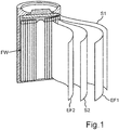
- Fig. 1 shows schematically the structure of a battery coil of a lithium-ion battery cell.
- the film roll FW contains four components S1, S2, EF1, EF2 which are arranged one above the other and are wound, for example, by means of a cylindrical winding mandrel.
- a separator S1, a first electrode film EF1, a second separator S2 and a second electrode film EF2 are arranged one above the other in the order mentioned and are then wound up.
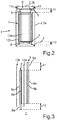
- Fig. 2 is schematically shown a sectional view through an exemplary embodiment of a battery cell according to the improved concept.
- the battery cell 1 has a cell housing 2 which contains a cylindrical trunk body 2a and a cover component 2b.
- the fuselage body 2a is closed at one axial end of the cylindrical casing by a bottom surface 3. At an opposite end, the body 2a itself is open and is closed by the cover component 2b.
- Both the bottom surface 3 and a cover surface 5 of the cover component 2b are electrically conductive.
- the battery cell 1 therefore has, for example, an insulator ring 13 which is arranged between the cover component 2b and the body body 2a in order to electrically isolate the cover component 2b from the body body 2a.
- the battery cell 1 also has a foil wrap 7. At a first axial end of the film roll 7, the film roll 7 is materially connected to a first contact material 4 and thereby electrically connected to the body 2a on the bottom surface 3.
- the film roll 7 can be materially connected to the cover component 2b on the cover surface at a second axial end of the film roll 7 opposite the first axial end via a second electrically conductive contact material 6, in particular in order to electrically connect the film roll 7 to the cover component 2b.
- the film roll 7 has in particular a first electrode film 8 and a second electrode film 9.
- the first contact material 4 is in line with the first Electrode foil 8 in direct contact and is not electrically connected to the second electrode foil 9.
- the second contact material 6 is accordingly not electrically connected to the first electrode film and is in direct contact with the second electrode film.
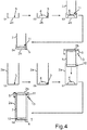
- FIG. 3 The structure of the film roll 7 is shown in FIG Fig. 3 not necessarily shown in more detail to scale. Fig. 3 can be understood as a sectional view through the film roll 7 in the unwound state.
- the first electrode foil 8 contains a first carrier foil 8a, for example an aluminum foil, as well as a first active material 8b arranged on both sides of the first carrier foil 8a.
- the first carrier film 8a is free of the first active material 8b in a first axial end region 10 of the film roll 7, so that the first contact material 4 is in direct electrical contact with the first carrier film 8a at the first axial end region 10 and is firmly connected to it.
- the second electrode foil 9 contains a second carrier foil 9a, for example a copper foil, as well as a first active material 9b arranged on both sides of the second carrier foil 9a.
- the first carrier film 8a is free of the second active material 9b in a second axial end region 11 of the film roll 7, so that the second contact material 6 is in direct electrical contact with the second carrier film 9a at the second axial end region 11 and is firmly connected to it.
- the first and second electrode foils 8, 9 are arranged axially offset from one another so that the first electrode foil 8 protrudes over the second electrode foil 9 in the first axial end area 10 and the second electrode foil 9 protrudes over the first electrode foil 8 in the second axial end area 11 .
- the respective surfaces of the first and second carrier foils 8a, 8b are, for example, continuously coated with the respective active materials 8b, 9b.
- the film roll 7 has a separator 12 a, which is arranged between the first electrode film 8 and the second electrode film 9.
- the separator 12a is arranged between the electrode foils 8, 9 in such a way that the corresponding mutually facing parts of the active materials 8b, 9b are not in direct contact.
- a further separator 12b of the film roll 7 is arranged on a side of the first electrode film 8 facing away from the separator 12a or on a side of the second electrode film 9 facing away from the separator 12a. In the developed state, the further separator 12b is also located between the electrode foils 8, 9, as in FIG Fig. 2 can be seen.
- the battery cell 1 can for example be produced by means of a production method or a further production method according to the improved concept.
- FIG. 4 Such manufacturing processes are in Fig. 4 is shown as a flow chart.
- step S1 the cover component 2b is provided and in step S2 the second electrically conductive contact material 6 is introduced into the cover component 2b, in particular on the cover surface 5.
- the second contact material 6 can be introduced into the cover component 2b, for example, as a metal paste, solder paste or plastic material with a polymer matrix and conductive metallic particles or carbon particles embedded therein.
- the second contact material 6 can also be introduced as a solder plate or other solder template.
- step S3 the film roll 7 is brought into contact with the second contact material 6 with the second axial end region 11 first.
- the film roll 7 can optionally partially penetrate into the second contact material 6.
- step S4 the second contact material 6 is heated from outside the cover component 2b, for example inductively or by means of a heating plate.
- the first contact material or the film roll 7 after Heating are actively cooled in order to avoid excessive heating of the active materials 8b, 9b.
- step S5 the trunk body 2a is provided and in step S6 the first contact material 4 is introduced into the trunk body 2a, in particular brought onto the floor surface 3.
- step S6 the first contact material 4 is introduced into the trunk body 2a, in particular brought onto the floor surface 3.
- step S7 the film roll 7, which is connected, for example, to the cover component 2b via the second contact material 6 as described above, is introduced into the body 2a with the first axial end region 10 first and connected to the first contact material 4.
- step S8 the first contact material 4 is heated from outside the cell housing 2 in order to connect the first contact material 4 to the first electrode foil 8 in a materially bonded manner.
- Steps S1 to S4 do not necessarily have to be carried out.
- the method can also only contain steps S5 to S8, the film roll 7 being connected beforehand or subsequently in an alternative manner to the cover component 2b or to another component of the cell housing 2.
- Steps S1 to S4 can likewise be carried out without necessarily having to be followed by steps S5 to S8.
- the film roll 7 is then connected to the fuselage body 2a in an alternative manner.
- the method includes the described material connection of the film roll 7 to the first contact material 4 and / or the material connection of the film roll 7 to the second contact material 6.
- the improved concept achieves the production of a battery cell with reduced overall impedance and at the same time ensuring good heat dissipation from the foil wrap.
Landscapes
- Chemical & Material Sciences (AREA)
- Chemical Kinetics & Catalysis (AREA)
- Electrochemistry (AREA)
- General Chemical & Material Sciences (AREA)
- Engineering & Computer Science (AREA)
- Manufacturing & Machinery (AREA)
- Materials Engineering (AREA)
- Battery Electrode And Active Subsutance (AREA)
Abstract
Description
- Die vorliegende Erfindung betrifft ein Herstellungsverfahren für eine Batteriezelle sowie eine entsprechende Batteriezelle.
- Batteriezellen, insbesondere Zellen von Lithiumionenakkumulatoren, weisen häufig Folienwickel auf, in denen zwei Folien, welche die Elektroden der Zelle darstellen, durch Separatoren voneinander getrennt aufgewickelt sind und die sich in einem Zellengehäuse befinden. Um die Elektrodenfolien elektrisch mit den entsprechenden Teilen des Zellengehäuses zu verbinden, werden in bekannten Batteriezellen Stromabnehmerstreifen (englisch "Taps") verwendet, die mit den Elektrodenfolien und ebenso mit den entsprechenden Gehäuseteilen verlötet oder verschweißt werden. Die Stromabnehmerstreifen werden dabei stirnseitig aus den aufgewickelten Folienwickeln herausgeführt um mit dem Zellengehäuse verbunden zu werden.
- Innerhalb eines Folienwickels ist die Wärmeabfuhr in radialer Richtung in der Regel gering, sodass die Stromabnehmerstreifen auch einen großen Anteil am thermischen Batteriemanagement haben.
- Ein Nachteil dieser bekannten Batteriezellen ist jedoch, dass durch die bauartbedingten Verbindungsstellen zwischen Gehäuse und Stromabnehmerstreifen sowie zwischen Stromabnehmerstreifen und zugehöriger Elektrodenfolie die Gesamtimpedanz der Batteriezelle erhöht ist. Insbesondere bei Hochleistungsbatteriezellen ist eine möglichst geringe Gesamtimpedanz jedoch von hoher Bedeutung. Auch kleine Steigerungen in der Gesamtimpedanz, wie sie beispielsweise durch die beschriebenen Effekte zustande kommen, wirken sich negativ aus.
- Es ist daher eine Aufgabe der vorliegenden Erfindung, ein verbessertes Konzept für eine Batteriezelle anzugeben, mit dem die Gesamtimpedanz der Batteriezelle verringert werden kann, insbesondere ohne die Wärmeabfuhr zu verschlechtern.
- Erfindungsgemäß wird diese Aufgabe gelöst durch den jeweiligen Gegenstand der unabhängigen Patentansprüche. Weitere Ausführungsformen sind Gegenstand der abhängigen Ansprüche.
- Das verbesserte Konzept beruht auf der Idee, einen Folienwickel an einem axialen Ende über ein elektrisch leitfähiges Kontaktmaterial direkt mit den entsprechenden Kontaktflächen im Inneren des Zellengehäuses elektrisch und stoffschlüssig zu verbinden.
- Gemäß dem verbesserten Konzept wird ein Herstellungsverfahren zur Herstellung einer Batteriezelle angegeben. Dazu wird ein elektrisch leitfähiges erstes Kontaktmaterial im Inneren eines Zellengehäuses auf einer Bodenfläche des Zellengehäuses angeordnet. Danach wird ein Folienwickel mit einem ersten axialen Ende des Folienwickels voran in das Zellengehäuse eingeführt, sodass eine erste Elektrodenfolie des Folienwickels an dem ersten axialen Ende in direktem Kontakt mit dem ersten Kontaktmaterial steht. Danach wird das erste Kontaktmaterial stoffschlüssig mit der ersten Elektrodenfolie verbunden, um die erste Elektrodenfolie elektrisch mit dem Zellengehäuse, insbesondere der Bodenfläche, zu verbinden.
- Insbesondere kann das Zellengehäuse einen zylinderförmigen Rumpfkörper aufweisen, der insbesondere einen zylinderförmigen Mantel und einen Boden aufweist, welcher insbesondere der Basis des Zylinders entspricht und dessen im Inneren des Zellgehäuses liegende Seite der Bodenfläche entspricht.
- An einem dem Boden gegenüberliegenden Ende des zylinderförmigen Mantels ist der Rumpfkörper beispielsweise geöffnet, um den Folienwickel einführen zu können. Eine Deckelkomponente des Zylindergehäuses kann beispielsweise verwendet werden, um das Zellengehäuse beziehungsweise den Rumpfkörper an diesem Ende zu schließen.
- Der Folienwickel ist insbesondere ebenfalls zylinderförmig oder im Wesentlichen zylinderförmig, insbesondere kreiszylinderförmig, ausgestaltet.
- Das erste Kontaktmaterial ist, insbesondere nach der stoffschlüssigen Verbindung mit dem ersten Ende des Folienwickels, elektrisch und beispielsweise thermisch leitfähig. Nichtsdestotrotz kann das erste Kontaktmaterial auch elektrisch nicht leitfähige Komponenten, beispielsweise ein Polymer oder einen sonstigen Kunststoff, enthalten.
- Dass die erste Elektrodenfolie in direktem Kontakt mit dem ersten Kontaktmaterial steht, kann insbesondere derart verstanden werden, dass zwischen dem ersten Kontaktmaterial und der ersten Elektrodenfolie keine weitere Komponente zur Kontaktierung angeordnet ist. Insbesondere erfolgt die elektrische Kontaktierung der Elektrodenfolie mit der Bodenfläche ausschließlich durch das erste Kontaktmaterial.
- Die erste Elektrodenfolie weist insbesondere eine erste Trägerfolie auf, die mit einem ersten Aktivmaterial wenigstens zum Teil beschichtet ist, insbesondere beidseitig.
- Insbesondere steht die erste Trägerfolie, also ein nicht mit dem ersten Aktivmaterial beschichteter Bereich der Trägerfolie, mit dem ersten Kontaktmaterial in direktem Kontakt, nachdem der Folienwickel in das Zellengehäuse eingeführt wurde. Insbesondere wird das erste Kontaktmaterial stoffschlüssig mit dem Bereich der ersten Trägerfolie verbunden, der nicht mit dem ersten Aktivmaterial verbunden ist, um die erste Trägerfolie elektrisch mit dem Zellengehäuse zu verbinden.
- Der Begriff "axial" kann hier und im Folgenden beispielsweise bezogen auf eine Wickelachse des Folienwickels und/oder bezogen auf eine Symmetrieachse des zylinderförmigen Mantels des Zellengehäuses verstanden werden, wobei diese beiden Achsen im fertiggestellten Zustand der Batteriezelle beispielsweise näherungsweise parallel zueinander oder näherungsweise identisch sind.
- Durch die stoffschlüssige Verbindung des ersten Kontaktmaterials mit der ersten Elektrodenfolie wird insbesondere auch die Bodenfläche, also das Zellengehäuse, stoffschlüssig mit dem ersten Kontaktmaterial verbunden.
- Nach einem Herstellungsverfahren gemäß dem verbesserten Konzept wie beschrieben sind außer dem Folienwickel selbst und dem ersten Kontaktmaterial keine weiteren Komponenten erforderlich, um den Folienwickel an dem ersten axialen Ende elektrisch mit dem Zellengehäuse zu verbinden. Die elektrische Verbindung mittels des ersten Kontaktmaterials gewährleistet zudem beispielsweise eine effiziente Wärmeabfuhr durch eine entsprechende thermische Leitfähigkeit des ersten Kontaktmaterials.
- Insbesondere sind keine Stromabnehmerstreifen, die im Folgenden auch als Taps bezeichnet werden, erforderlich, welche zum Einen an der ersten Elektrodenfolie und zum Anderen auch an dem Zellengehäuse befestigt werden müssten und damit eine höhere Gesamtimpedanz zur Folge hätten.
- Die Gesamtimpedanz der durch das Herstellungsverfahren gemäß dem verbesserten Konzept hergestellten Batteriezelle ist daher reduziert, ohne Einbußen bei der Wärmeabfuhr hinnehmen zu müssen.
- Durch das verbesserte Konzept ist es auch nicht erforderlich, nach dem Einführen des Folienwickels in das Zellengehäuse ein Lötwerkzeug oder ähnliches durch den Folienwickel hindurch oder an dem Folienwickel vorbeizuführen, um das erste axiale Ende mit der Bodenfläche verlöten zu können beziehungsweise über entsprechende Taps oder sonstige Kontaktkomponenten mit der Bodenfläche verbinden zu können.
- Gemäß zumindest einer Ausführungsform des Herstellungsverfahrens wird das erste Kontaktmaterial in einem flüssigen oder pastösen Zustand in das Zellengehäuse eingebracht. Das erste Kontaktmaterial kann also mittels einer Spritze oder Düse auf die Bodenfläche gebracht werden.
- Gemäß zumindest einer Ausführungsform wird das erste Kontaktmaterial als festes Plättchen, beispielsweise als Lötplättchen, also als Plättchen aus einem Lotmaterial, auch als Lotvorlage bezeichnet, in das Zellengehäuse eingebracht.
- Sowohl das Einbringen des Kontaktmaterials als Paste oder Flüssigkeit als auch das Einbringen des ersten Kontaktmaterials als Plättchen erlauben eine nachträgliche stoffschlüssige Verbindung des ersten Kontaktmaterials mit dem Folienwickel beziehungsweise der ersten Elektrodenfolie durch externe Mittel, beispielsweise durch Erhitzen von außen.
- Die erste Trägerfolie kann insbesondere als Metallfolie, beispielsweise als Kupferfolie oder Aluminiumfolie, ausgestaltet sein.
- Gemäß zumindest einer Ausführungsform werden, insbesondere um den Folienwickel vor dem Einführen des Folienwickels in das Zellengehäuse zu fertigen, die erste Elektrodenfolie und eine zweite Elektrodenfolie des Folienwickels übereinander angeordnet, sodass die erste Elektrodenfolie an einer dem ersten axialen Ende des Folienwickels entsprechenden Seite über die zweite Elektrodenfolie übersteht. Die übereinander angeordneten Elektrodenfolien werden dann gemeinsam aufgewickelt, um den Folienwickel zu fertigen.
- Optional können die Elektrodenfolien derart übereinander angeordnet werden, dass die zweite Elektrodenfolie an einer einem zweiten axialen Ende des Folienwickels, welches dem ersten axialen Ende des Folienwickels gegenüberliegt, entsprechenden Seite über die erste Elektrodenfolie übersteht.
- Bei der Anordnung der Elektrodenfolien übereinander befindet sich insbesondere ein Separator zwischen der ersten und der zweiten Elektrodenfolie. Ein weiterer Separator ist beispielsweise auf einer dem Separator beziehungsweise der zweiten Elektrodenfolie abgewandten Seite der ersten Elektrodenfolie angeordnet oder auf einer dem Separator beziehungsweise der ersten Elektrodenfolie abgewandten Seite der zweiten Elektrodenfolie.
- Das Aufwickeln der übereinander angeordneten Elektrodenfolien, insbesondere der Elektrodenfolien und der Separatoren, erfolgt beispielsweise durch Aufwickeln auf einen Wickeldorn.
- In solchen Ausführungsformen ist die zweite Elektrodenfolie in dem aufgewickelten Folienwickel daher von dem ersten axialen Ende des Folienwickels entfernt angeordnet, sodass die zweite Elektrodenfolie nicht in elektrischem Kontakt mit dem ersten Kontaktmaterial steht, insbesondere nachdem das erste Kontaktmaterial mit der ersten Elektrodenfolie verbunden wurde.
- Entsprechend kann auch die erste Elektrodenfolie von dem zweiten axialen Ende des Folienwickels beabstandet sein. Auch hier kann also der Folienwickel direkt durch die zweite Elektrodenfolie mit dem Zellengehäuse und gegebenenfalls mit einem zweiten elektrisch leitfähigen Kontaktmaterial verbunden werden.
- Insbesondere ermöglicht es diese Anordnung der Elektrodenfolien in dem Folienwickel, auf Taps zur Kontaktierung des Folienwickels zu verzichten und damit eine reduzierte Impedanz zu ermöglichen.
- Gemäß zumindest einer Ausführungsform des Herstellungsverfahrens wird der Folienwickel derart bereitgestellt, dass die erste Elektrodenfolie an dem ersten axialen Ende des Folienwickels über die zweite Elektrodenfolie übersteht. Optional kann der Folienwickel derart bereitgestellt werden, dass die zweite Elektrodenfolie an dem zweiten axialen Ende des Folienwickels über die erste Elektrodenfolie übersteht.
- Mit anderen Worten sind in solchen Ausführungsformen die Schritte zur Fertigung des Folienwickels nicht notwendigerweise Bestandteil des Herstellungsverfahrens nach dem verbesserten Konzept.
- Gemäß zumindest einer Ausführungsform ist die erste Trägerfolie in dem Bereich, in dem sie über die zweite Elektrodenfolie übersteht frei von dem ersten Aktivmaterial.
- Gemäß zumindest einer Ausführungsform ist die zweite Trägerfolie in einem Bereich, in dem sie über die erste Trägerfolie übersteht, frei von dem zweiten Aktivmaterial.
- Dadurch kann eine bessere, also insbesondere zuverlässigere und stabilere, Verbindung der Elektrodenfolien mit dem Zellengehäuse erfolgen.
- Gemäß zumindest einer Ausführungsform wird das erste Kontaktmaterial, insbesondere nachdem der Folienwickel in das Zellengehäuse eingeführt wurde, von außerhalb des Zellengehäuses erhitzt, um das erste Kontaktmaterial stoffschlüssig mit der ersten Elektrodenfolie zu verbinden.
- Dass die Erhitzung von außerhalb des Zellengehäuses erfolgt, kann insbesondere derart verstanden werden, dass zum Erhitzen des ersten Kontaktmaterials kein Werkzeug und keine Wärmequelle in das Innere des Zellengehäuses eingeführt werden. Stattdessen wird eine Heizvorrichtung oder ein Heizwerkzeug außerhalb des Gehäuses, beispielsweise in der Nähe des Bodens des Zellengehäuses, angeordnet, um das erste Kontaktmaterial von außerhalb des Zellengehäuses, insbesondere indirekt, zu erhitzen.
- Die Heizvorrichtung beziehungsweise das Heizwerkzeug kann beispielsweise eine Vorrichtung zum induktiven Erhitzen des ersten Kontaktmaterials und/oder des Zellengehäuses beinhalten oder eine Heizplatte auf der das Zellengehäuse angeordnet wird, beispielsweise mit dem Boden auf die Heizplatte gestellt wird.
- Dadurch wird eine besonders einfache Herstellung der Batteriezelle ermöglicht. Insbesondere dadurch, dass kein Werkzeug in das Gehäuse eingeführt werden muss, besteht nicht die Gefahr, dass der Folienwickel mechanisch beschädigt wird.
- Die Heizvorrichtung beziehungsweise das Heizwerkzeug kann auch eine Vorrichtung zum Erzeugen von Heißluft beinhalten, um das erste Kontaktmaterial zu erhitzen.
- Die Heizvorrichtung oder das Heizwerkzeug kann eine Vorrichtung zum Erzeugen von Infrarotstrahlung zum Erhitzen des ersten Kontaktmaterials enthalten.
- Die Heizvorrichtung kann auch ein Flüssigkeitsbad zum Erhitzen des ersten Kontaktmaterials beinhalten.
- Gemäß zumindest einer Ausführungsform werden die erste Elektrodenfolie beziehungsweise das Zellengehäuse mittels Ultraschall mit dem ersten Kontaktmaterial stoffschlüssig verbunden.
- Dabei kann das Erhitzen beispielsweise durch Ultraschall unterstützt werden oder das Verbinden mittels Ultraschall ersetzt das Erhitzen.
- Gemäß zumindest einer Ausführungsform, insbesondere einer Ausführungsform in der das erste Kontaktmaterial erhitzt wird, um das erste Kontaktmaterial stoffschlüssig mit der ersten Elektrodenfolie zu verbinden, wird das erste Kontaktmaterial beziehungsweise die erste Elektrodenfolie beziehungsweise der Folienwickel von außerhalb des Zellengehäuses gekühlt, insbesondere aktiv gekühlt, beispielsweise mittels einer externen Kühlvorrichtung.
- Durch das Kühlen wird verhindert, dass sich die Aktivmaterialien und/oder die Separatoren des Folienwickels zu stark erhitzen und gegebenenfalls beschädigt werden.
- Beispielsweise kann die Erhitzung nach einer vorgegebenen Heizzeit beendet werden. Die Kühlung kann am Ende der Heizzeit oder nach Ende der Heizzeit, insbesondere unmittelbar danach, erfolgen.
- Gemäß zumindest einer Ausführungsform beinhaltet das erste Kontaktmaterial eine Metallkomponente.
- Gemäß zumindest einer Ausführungsform wird die Metallkomponente durch das Erhitzen des ersten Kontaktmaterials geschmolzen oder gesintert.
- Wird das erste Kontaktmaterial beispielsweise in festem Zustand in das Zellengehäuse eingebracht, so kann das erste Kontaktmaterial durch das Erhitzen geschmolzen werden. Erstarrt das erste Kontaktmaterial dann wieder, ist es stoffschlüssig mit der ersten Elektrodenfolie verbunden.
- Wir das erste Kontaktmaterial pastös oder flüssig in das Zellengehäuse eingebracht, kann der Folienwickel, insbesondere die erste Elektrodenfolie, beispielsweise in das erste Kontaktmaterial gesteckt werden und durch das Erhitzen können beispielsweise Metallpartikel der Metallkomponente aufgeschmolzen oder gesintert werden und/oder das erste Kontaktmaterial kann entbindert oder von Lösemittel befreit werden.
- Handelt es sich bei dem ersten Kontaktmaterial um ein festes Lotmaterial, also insbesondere ein Lotplättchen oder eine feste Lotvorlage, kann das erste Kontaktmaterial durch das Erhitzen mit der ersten Elektrodenfolie beziehungsweise mit dem Zellengehäuse verlötet werden.
- Handelt es sich bei dem ersten Kontaktmaterial um eine Lotpaste, kann durch das Erhitzen beispielsweise ein Wiederverflüssigungs-Lötprozess (englisch: "reflow soldering") durchgeführt werden.
- Gemäß zumindest einer Ausführungsform enthält das erste Kontaktmaterial eine Polymerkomponente.
- Gemäß zumindest einer Ausführungsform wird die Polymerkomponente durch das Erhitzen des ersten Kontaktmaterials von außerhalb des Zellengehäuses geschmolzen.
- Beispielsweise kann das erste Kontaktmaterial die Polymerkomponente, die auch als Polymermatrix oder Polymerträgermatrix bezeichnet werden kann, ein elektrisch leitfähiges Pulver oder elektrisch leitfähige Partikel aufnehmen, beziehungsweise diese Partikel können in dem Polymermaterial eingebettet sein. Die elektrisch leitfähigen Partikel können beispielsweise Metall oder Partikel aus einem Kohlenstoffmaterial beinhalten, beispielsweise Graphit, Graphen oder Kohlenstoffnanoröhrchen. Alternativ oder zusätzlich kann die Polymerkomponente dotiert sein, um die elektrische Leitfähigkeit zu erzielen.
- Durch das Erhitzen und Aufschmelzen der Polymerkomponente kann die erste Elektrodenfolie dann mit dem ersten Kontaktmaterial stoffschlüssig verbunden werden.
- Die elektrisch leitfähigen Partikel können, beispielsweise wenn es sich um Metallpartikel handelt, durch das Erhitzen ebenfalls geschmolzen, teilweise geschmolzen oder gesintert werden.
- Gemäß zumindest einer Ausführungsform wird durch das Erhitzen eine Polymerisierungsreaktion der Polymerkomponente initiiert.
- Gemäß zumindest einer Ausführungsform ist das erste Kontaktmaterial als Klebstoff, insbesondere als elektrisch leitfähiger Klebstoff ausgestaltet.
- Gemäß zumindest einer Ausführungsform wird der Klebstoff durch das Erhitzen gehärtet, insbesondere abgebunden oder chemisch gehärtet.
- Gemäß dem verbesserten Konzept wird auch ein weiteres Herstellungsverfahren für eine Batteriezelle angegeben. Gemäß dem weiteren Herstellungsverfahren wird ein elektrisch leitfähiges zweites Kontaktmaterial auf einer inneren Deckelfläche einer Deckelkomponente eines Zellengehäuses zum Verschließen des Zellengehäuses angeordnet. Danach wird eine zweite Elektrodenfolie eines Folienwickels an einem zweiten axialen Ende des Folienwickels, welches insbesondere einem ersten axialen Ende des Folienwickels gegenüber angeordnet ist, in direkten Kontakt mit dem zweiten Kontaktmaterial gebracht. Danach wird das zweite Kontaktmaterial stoffschlüssig mit der zweiten Elektrodenfolie verbunden, um die zweite Elektrodenfolie elektrisch mit der Deckelkomponente zu verbinden.
- Die innere Deckelfläche der Deckelkomponente befindet sich insbesondere innerhalb des Zellengehäuses, nachdem der Rumpfkörper des Zellengehäuses durch die Deckelkomponente des Zellengehäuses verschlossen wurde.
- Gemäß zumindest einer Ausführungsform des weiteren Herstellungsverfahrens wird das zweite Kontaktmaterial von außerhalb der Deckelkomponente erhitzt, um das zweite Kontaktmaterial stoffschlüssig mit der zweiten Elektrodenfolie zu verbinden.
- Sämtliche Ausführungsformen des weiteren Herstellungsverfahrens nach dem verbesserten Konzept können mit sämtlichen Ausführungsformen des Herstellungsverfahrens nach dem verbesserten Konzept kombiniert werden.
- Insbesondere können die oben beschriebenen Verfahrensschritte des weiteren Herstellungsverfahrens ausgeführt werden, bevor die Verfahrensschritte des Herstellungsverfahrens nach dem verbesserten Konzept ausgeführt werden.
- Sämtliche Ausführungsformen, die für das Herstellungsverfahren nach dem verbesserten Konzept beschrieben wurden, können analog auf das weitere Herstellungsverfahren übertragen werden. Dabei nehmen die erste und die zweite Elektrodenfolie vertauschte Rollen ein, ebenso wie das erste und das zweite axiale Ende des Folienwickels, das erste und das zweite Kontaktmaterial sowie die Bodenfläche und die Deckelfläche.
- Mit anderen Worten kann die zweite Elektrodenfolie derart mittels des zweiten Kontaktmaterials mit der Deckelfläche verbunden werden, wie dies oben bezüglich der Verbindung der ersten Elektrodenfolie mittels des ersten Kontaktmaterials mit der Bodenfläche beschrieben wurde.
- Gemäß zumindest einer Ausführungsform des weiteren Herstellungsverfahrens nach dem verbesserten Konzept wird der Folienwickel, insbesondere nachdem die zweite Elektrodenfolie stoffschlüssig mit dem zweiten Kontaktmaterial verbunden wurde, mit dem ersten axialen Ende des Folienwickels voran in das Zellengehäuse eingeführt.
- Dieser Verfahrensschritt des weiteren Herstellungsverfahrens kann auch dem weiter oben beschriebenen entsprechenden Verfahrensschritt des Herstellungsverfahrens entsprechen.
- Gemäß zumindest einer Ausführungsform wird der Rumpfkörper beziehungsweise wird das Zellengehäuse nach dem Einführen des Folienwickels mit der Deckelkomponente verbunden, um das Zellengehäuse zu verschließen.
- Beispielsweise kann dabei ein Isolationselement zwischen dem Rumpfkörper und der Deckelkomponente angeordnet werden, um diese elektrisch voneinander zu isolieren.
- Gemäß dem verbesserten Konzept wird auch eine Batteriezelle angegeben, die insbesondere gemäß einem Herstellungsverfahren und/oder einem weiteren Herstellungsverfahren nach dem verbesserten Konzept hergestellt wurde. Die Batteriezelle weist ein Zellengehäuse und ein im Inneren des Zellengehäuses auf einer Bodenfläche des Zellengehäuses angeordnetes elektrisch leitfähiges erstes Kontaktmaterial auf und/oder ein im Inneren des Zellengehäuses auf einer Deckelfläche des Zellengehäuses angeordnetes elektrisch leitfähiges zweites Kontaktmaterial auf. Die Batteriezelle weist einen Folienwickel mit einer ersten und einer zweiten Elektrodenfolie auf. Die erste Elektrodenfolie ist an einem ersten axialen Ende des Folienwickels stoffschlüssig mit dem ersten Kontaktmaterial direkt verbunden und das erste Kontaktmaterial verbindet die erste Elektrodenfolie, insbesondere direkt, elektrisch mit dem Zellengehäuse, insbesondere der Bodenfläche und/oder die zweite Elektrodenfolie ist an einem zweiten, dem ersten axialen Ende des Folienwickels gegenüberliegenden, zweiten axialen Ende des Folienwickels stoffschlüssig mit dem zweiten Kontaktmaterial direkt verbunden und das zweite Kontaktmaterial verbindet die zweite Elektrodenfolie, insbesondere direkt, elektrisch mit dem Zellengehäuse, insbesondere der Deckelkomponente, insbesondere der Deckelfläche.
- Die bezüglich der Herstellungsverfahren beschriebenen Vorteile übertragen sich auf die Batteriezelle nach dem verbesserten Konzept.
- Gemäß zumindest einer Ausführungsform der Batteriezelle liegt das erste Kontaktmaterial als gehärtetes oder ausgehärtetes, vormals flüssiges oder pastöses, Material vor.
- Gemäß zumindest einer Ausführungsform liegt das erste Kontaktmaterial als Lotmaterial vor, welches vor einem Lötvorgang zum Verbinden mit der ersten Elektrodenfolie als festes Lötplättchen vorlag.
- Gemäß zumindest einer Ausführungsform weist das Zellengehäuse eine Deckelkomponente, beispielsweise eine napfförmige oder zylindrische Deckelkomponente, auf, die beispielsweise auf den Rumpfkörper des Zellengehäuses geschoben ist.
- Gemäß zumindest einer Ausführungsform der Batteriezelle ist zwischen dem Rumpfkörper und der Deckelkomponente ein Isolationselement, beispielsweise ein Isolatorring, zur elektrischen Isolierung der Deckelkomponente von dem Rumpfkörper, angeordnet.
- Gemäß zumindest einer Ausführungsform ist die Batteriezelle als Lithium-Ionen-Zelle, insbesondere als Lithium-Ionen-Akkumulator, ausgestaltet.
- Gemäß zumindest einer Ausführungsform ist die Batteriezelle ohne Stromabnehmerstreifen ausgestaltet, also ohne Taps (englisch: "tapless design").
- Gemäß zumindest einer Ausführungsform der Batteriezelle steht die erste Elektrodenfolie in einem vorgegebenen ersten axialen Endbereich des Folienwickels beziehungsweise der ersten Elektrodenfolie über die zweite Elektrodenfolie über.
- Gemäß zumindest einer Ausführungsform steht die zweite Elektrodenfolie in einem vorgegebenen zweiten axialen Endbereich des Folienwickels beziehungsweise der zweiten Elektrodenfolie über die erste Elektrodenfolie über.
- Gemäß zumindest einer Ausführungsform weist die erste Elektrodenfolie eine erste elektrisch leitfähige Trägerfolie auf sowie ein erstes Aktivmaterial, das beidseitig auf der ersten Trägerfolie als jeweilige Schicht angeordnet ist.
- Gemäß zumindest einer Ausführungsform weist die zweite Elektrodenfolie eine zweite elektrisch leitfähige Trägerfolie auf sowie ein zweites Aktivmaterial, das beidseitig auf der zweiten Trägerfolie als jeweilige Schicht angeordnet ist.
- Die Schichten aus den Aktivmaterialien sind dabei nicht notwendigerweise zusammenhängend.
- Die Trägerfolien können beispielsweise jeweils ein Metall oder eine Metalllegierung beinhalten. Beispielsweise enthält eine der Trägerfolien, insbesondere die erste Trägerfolie, Aluminium oder eine Aluminiumlegierung oder besteht aus Aluminium beziehungsweise der Aluminiumlegierung. Beispielsweise enthält eine der Trägerfolien, insbesondere die zweite Elektrodenfolie, Kupfer oder eine Kupferlegierung enthalten beziehungsweise besteht aus Kupfer oder der Kupferlegierung.
- Gemäß zumindest einer Ausführungsform ist die erste Trägerfolie in dem ersten axialen Endbereich frei von dem ersten Aktivmaterial und/oder die zweite Trägerfolie ist in dem zweiten axialen Endbereich frei von dem zweiten Aktivmaterial.
- Mit anderen Worten erstrecken sich die Aktivmaterialien auf den gegenüberliegenden Oberflächen der jeweiligen Trägerfolie in einem jeweiligen Bereich, der den ersten beziehungsweise den zweiten axialen Endbereich nicht enthält.
- Mit anderen Worten liegt die erste Trägerfolie in dem ersten axialen Endbereich frei und/oder die zweite Trägerfolie liegt in dem zweiten axialen Endbereich frei. Mit anderen Worten steht die erste Trägerfolie in direktem Kontakt mit dem ersten Kontaktmaterial und/oder die zweite Trägerfolie steht in direktem Kontakt mit dem zweiten Kontaktmaterial.
- Gemäß zumindest einer Ausführungsform ist ein Separator zwischen der ersten Elektrodenfolie und der zweiten Elektrodenfolie angeordnet, insbesondere in einem Bereich, in dem sich das erste oder das zweite Aktivmaterial befindet.
- Gemäß zumindest einer Ausführungsform ist der Separator im abgewickelten Zustand des Folienwickels zwischen den Elektrodenfolien angeordnet.
- Gemäß zumindest einer Ausführungsform enthält der Folienwickel einen weiteren Separator zwischen den Elektrodenfolien.
- Im abgewickelten Zustand des Folienwickels ist der weitere Separator beispielsweise auf einer dem Separator abgewandten Seite der ersten Elektrodenfolie oder einer dem Separator abgewandten Seite der zweiten Elektrodenfolie angeordnet.
- Gemäß zumindest einer Ausführungsform enthält das erste Kontaktmaterial ein erstes Trägermaterial und in dem ersten Trägermaterial eingebettete elektrisch leitfähige erste Partikel.
- Gemäß zumindest einer Ausführungsform enthält das zweite Kontaktmaterial ein zweites Trägermaterial und in dem zweiten Trägermaterial eingebettete elektrisch leitfähige zweite Partikel.
- Das Trägermaterial kann auch als Matrixmaterial bezeichnet werden.
- Das Trägermaterial kann beispielsweise ein Polymermaterial beinhalten.
- Die elektrisch leitfähigen Partikel können auch als Granulat, Pulver oder Staub, gegebenenfalls in aufgeschmolzenen oder teilweise geschmolzenen Zustand verstanden werden.
- Gemäß zumindest einer Ausführungsform enthalten die ersten und/oder die zweiten Partikel ein Metall oder bestehen aus dem Metall.
- Je nach elektrochemischem System das für die Batteriezelle verwendet wird, also insbesondere je nachdem, welche Aktivmaterialien verwendet werden, können gegebenenfalls unterschiedliche Metalle verwendet werden, die elektrochemisch mit den Lade- und Entladevorgängen in der Batteriezelle nicht oder nicht signifikant wechselwirken. Beispielsweise können Edelmetalle eingesetzt werden.
- Gemäß zumindest einer Ausführungsform enthalten die ersten und/oder die zweiten Partikel ein Kohlenstoffmaterial oder bestehen aus dem elektrisch leitfähigen Kohlenstoffmaterial.
- Dies hat den Vorteil, dass das das Kohlenstoffmaterial in Kombination mit verschiedenen Aktivmaterialien eingesetzt werden kann.
- Das elektrisch leitfähige Kohlenstoffmaterial enthält beispielsweise Graphit, Graphen und/oder Kohlenstoffnanoröhrchen.
- Gemäß zumindest einer Ausführungsform beinhaltet das erste Kontaktmaterial und/oder das zweite Kontaktmaterial ein Lotmaterial.
- Das Lotmaterial kann beispielsweise als Lotpaste, Lotplättchen oder Lotvorlage ausgestaltet sein, insbesondere als Edelmetalllotmaterial.
- Gemäß zumindest einer Ausführungsform liegt das erste Kontaktmaterial und/oder das zweite Kontaktmaterial in der Batteriezelle als aufgeschmolzenes und wieder erstarrtes oder als gesintertes Material vor.
- Gemäß zumindest einer Ausführungsform enthält das erste Kontaktmaterial und/oder enthält das zweite Kontaktmaterial einen Klebstoff.
- Weitere Ausführungsformen der Batteriezelle nach dem verbesserten Konzept folgen unmittelbar und direkt aus den verschiedenen Ausgestaltungsformen des Herstellungsverfahrens und des weiteren Herstellungsverfahrens nach dem verbesserten Konzept und jeweils umgekehrt.
- In den Figuren zeigen:
- Fig. 1
- schematisch den Aufbau eines Folienwickels für eine Batteriezelle;
- Fig. 2
- eine schematische Schnittdarstellung durch eine beispielhafte Ausführungsform einer Batteriezelle nach dem verbesserten Konzept;
- Fig. 3
- eine Anordnung von Elektrodenfolien und Separatoren in einem Folienwickel zur Verwendung in einer weiteren beispielhaften Ausführungsform einer Batteriezelle nach dem verbesserten Konzept; und
- Fig. 4
- ein Ablaufdiagramm einer beispielhaften Ausführungsform eines Herstellungsverfahrens sowie einer beispielhaften Ausführungsform eines weiteren Herstellungsverfahrens nach dem verbesserten Konzept.
-
Fig. 1 zeigt schematisch den Aufbau eines Batteriewickels einer Lithium-Ionen-Batteriezelle. - Der Folienwickel FW enthält vier übereinander angeordnete und beispielsweise mittels eines einem zylindrischen Wickeldorns aufgewickelte Komponenten S1, S2, EF1, EF2.
- Im abgewickelten Zustand sind beispielsweise ein Separator S1, eine erste Elektrodenfolie EF1, ein zweiter Separator S2 und eine zweite Elektrodenfolie EF2 in der genannten Reihenfolge übereinander angeordnet und werden dann aufgewickelt.
- In
Fig. 2 ist schematisch eine Schnittdarstellung durch eine beispielhafte Ausführungsform einer Batteriezelle nach dem verbesserten Konzept gezeigt. - Die Batteriezelle 1 weist ein Zellengehäuse 2 auf, das einen zylindrischen Rumpfkörper 2a und eine Deckelkomponente 2b enthält. Der Rumpfkörper 2a ist an einem axialen Ende des zylindrischen Mantels durch eine Bodenfläche 3 geschlossen. An einem gegenüberliegenden Ende ist der Rumpfkörper 2a selbst offen und wird durch die Deckelkomponente 2b verschlossen.
- Sowohl die Bodenfläche 3 als auch eine Deckelfläche 5 der Deckelkomponente 2b sind elektrisch leitfähig. Daher weist die Batteriezelle 1 beispielsweise einen Isolatorring 13 auf, der zwischen der Deckelkomponente 2b und dem Rumpfkörper 2a angeordnet ist, um die Deckelkomponente 2b von dem Rumpfkörper 2a elektrisch zu isolieren.
- Die Batteriezelle 1 weist auch einen Folienwickel 7 auf. An einem ersten axialen Ende des Folienwickels 7 ist der Folienwickel 7 stoffschlüssig mit einem ersten Kontaktmaterial 4 verbunden und dadurch elektrisch mit dem Rumpfkörper 2a an der Bodenfläche 3 verbunden.
- Optional kann der Folienwickel 7 an einem dem ersten axialen Ende gegenüberliegenden zweiten axialen Ende des Folienwickels 7 über ein zweites elektrisch leitfähiges Kontaktmaterial 6 mit der Deckelkomponente 2b an der Deckelfläche stoffschlüssig verbunden sein, insbesondere um den Folienwickel 7 elektrisch mit der Deckelkomponente 2b zu verbinden.
- Der Folienwickel 7 weist dabei insbesondere eine erste Elektrodenfolie 8 und eine zweite Elektrodenfolie 9 auf. Das erste Kontaktmaterial 4 steht dabei mit der ersten Elektrodenfolie 8 in direktem Kontakt und ist nicht elektrisch mit der zweiten Elektrodenfolie 9 verbunden. Das zweite Kontaktmaterial 6 ist entsprechend nicht mit der ersten Elektrodenfolie elektrisch verbunden und steht mit der zweiten Elektrodenfolie in direktem Kontakt.
- Der Aufbau des Folienwickels 7 ist in
Fig. 3 nicht notwendigerweise maßstabsgetreu genauer dargestellt.Fig. 3 kann als Schnittdarstellung durch den Folienwickel 7 im abgewickelten Zustand verstanden werden. - Die erste Elektrodenfolie 8 enthält eine erste Trägerfolie 8a, beispielsweise eine Aluminiumfolie, sowie beidseitig auf der ersten Trägerfolie 8a angeordnet ein erstes Aktivmaterial 8b. Dabei ist die erste Trägerfolie 8a in einem ersten axialen Endbereich 10 des Folienwickels 7 frei von dem ersten Aktivmaterial 8b, sodass das erste Kontaktmaterial 4 an dem ersten axialen Endbereich 10 in direktem elektrischen Kontakt mit der ersten Trägerfolie 8a steht und mit dieser stoffschlüssig verbunden ist.
- Die zweite Elektrodenfolie 9 enthält eine zweite Trägerfolie 9a, beispielsweise eine Kupferfolie, sowie beidseitig auf der zweiten Trägerfolie 9a angeordnet ein erstes Aktivmaterial 9b. Dabei ist die erste Trägerfolie 8a in einem zweiten axialen Endbereich 11 des Folienwickels 7 frei von dem zweiten Aktivmaterial 9b, sodass das zweite Kontaktmaterial 6 an dem zweiten axialen Endbereich 11 in direktem elektrischen Kontakt mit der zweiten Trägerfolie 9a steht und mit dieser stoffschlüssig verbunden ist.
- Die erste und die zweite Elektrodenfolie 8, 9 sind dabei axial versetzt zueinander angeordnet, sodass die erste Elektrodenfolie 8 in dem ersten axialen Endbereich 10 über die zweite Elektrodenfolie 9 übersteht und die zweite Elektrodenfolie 9 in dem zweiten axialen Endbereich 11 über die erste Elektrodenfolie 8 übersteht.
- In den Bereichen, in denen die erste und die zweite Elektrodenfolie 8, 9 einander überlappen sind die jeweiligen Oberflächen der ersten und der zweiten Trägerfolie 8a, 8b beispielsweise durchgängig mit den jeweiligen Aktivmaterialien 8b, 9b beschichtet.
- Der Folienwickel 7 weist einen Separator 12a auf, der zwischen der ersten Elektrodenfolie 8 und der zweiten Elektrodenfolie 9 angeordnet ist. Insbesondere ist der Separator 12a derart zwischen den Elektrodenfolien 8, 9 angeordnet, dass die entsprechenden einander zugewandten Teile der Aktivmaterialien 8b, 9b nicht in direktem Kontakt stehen. Ein weiterer Separator 12b des Folienwickels 7 ist auf einer dem Separator 12a abgewandten Seite der ersten Elektrodenfolie 8 beziehungsweise auf einer dem Separator 12a abgewandten Seite der zweiten Elektrodenfolie 9 angeordnet. Im abgewickelten Zustand befindet sich auch der weitere Separator 12b zwischen den Elektrodenfolien 8, 9, wie in
Fig. 2 ersichtlich ist. - Die Batteriezelle 1 kann beispielsweise mittels eines Herstellungsverfahrens beziehungsweise eines weiteren Herstellungsverfahrens nach dem verbesserten Konzept hergestellt sein.
- Solche Herstellungsverfahren sind in
Fig. 4 ist als Ablaufdiagramm dargestellt. - In Schritt S1 wird die Deckelkomponente 2b bereitgestellt und in Schritt S2 wird das zweite elektrisch leitfähige Kontaktmaterial 6 in die Deckelkomponente 2b, insbesondere auf der Deckelfläche 5, eingebracht. Das zweite Kontaktmaterial 6 kann beispielsweise als Metallpaste, Lotpaste oder Kunststoffmaterial mit einer Polymermatrix und darin eingebetteten leitfähigen metallischen Partikeln oder Kohlenstoffpartikeln in die Deckelkomponente 2b eingebracht werden. Alternativ kann das zweite Kontaktmaterial 6 auch als Lotplättchen oder sonstige Lotvorlage eingebracht werden.
- In Schritt S3 wird der Folienwickel 7 mit dem zweiten axialen Endbereich 11 voran mit dem zweiten Kontaktmaterial 6 in Kontakt gebracht. Je nach Ausgestaltung des zweiten Kontaktmaterials 6, insbesondere je nachdem ob das zweite Kontaktmaterial 6 fest, flüssig oder pastös ist, kann der Folienwickel 7 dabei gegebenenfalls teilweise in das zweite Kontaktmaterial 6 eindringen.
- In Schritt S4 wird das zweite Kontaktmaterial 6 von außerhalb der Deckelkomponente 2b erhitzt, beispielsweise induktiv oder mittels einer Heizplatte. Optional kann das erste Kontaktmaterial beziehungsweise der Folienwickel 7 nach dem Erhitzen aktiv gekühlt werden, um ein zu starkes Erhitzen der Aktivmaterialien 8b, 9b zu vermeiden.
- In Schritt S5 wird der Rumpfkörper 2a bereitgestellt und in Schritt S6 wird das erste Kontaktmaterial 4 in den Rumpfkörper 2a eingebracht, insbesondere auf die Bodenfläche 3 gebracht. Hinsichtlich der Materialien für das erste Kontaktmaterial 4 gilt das oben für das zweite Kontaktmaterial 6 erläuterte analog.
- In Schritt S7 wird der Folienwickel 7, der wie oben beschrieben beispielsweise mit der Deckelkomponente 2b über das zweite Kontaktmaterial 6 verbunden ist, mit dem ersten axialen Endbereich 10 voran in den Rumpfkörper 2a eingeführt und mit dem ersten Kontaktmaterial 4 in Verbindung gebracht. Analog wie oben beschrieben wird im Schritt S8 das erste Kontaktmaterial 4 von außerhalb des Zellengehäuses 2 erhitzt, um das erste Kontaktmaterial 4 stoffschlüssig mit der ersten Elektrodenfolie 8 zu verbinden.
- Die Schritte S1 bis S4 müssen nicht notwendigerweise durchgeführt werden. Insbesondere kann das Verfahren auch lediglich die Schritte S5 bis S8 enthalten, wobei der Folienwickel 7 vorab oder nachträglich in einer alternativen Weise mit der Deckelkomponente 2b oder einer sonstigen Komponente des Zellengehäuses 2 verbunden wird.
- Ebenso können die Schritte S1 bis S4 durchgeführt werden, ohne dass notwendigerweise die Schritte S5 bis S8 darauf folgen müssen. Insbesondere wird dann der Folienwickel 7 in einer alternativen Weise mit dem Rumpfkörper 2a verbunden.
- Mit anderen Worten beinhaltet das Verfahren die beschriebene stoffschlüssige Verbindung des Folienwickels 7 mit dem ersten Kontaktmaterial 4 und/oder die stoffschlüssige Verbindung des Folienwickels 7 mit dem zweiten Kontaktmaterial 6.
- Wie beschrieben wird es durch das verbesserte Konzept erreicht, eine Batteriezelle mit reduzierter Gesamtimpedanz herzustellen und gleichzeitig eine gute Wärmeabfuhr aus dem Folienwickel zu gewährleisten.
-
- 1
- Batteriezelle
- 2
- Zellengehäuse
- 2a
- Rumpfkörper
- 2b
- Deckelkomponente
- 3
- Bodenfläche
- 4
- Kontaktmaterial
- 5
- Deckelfläche
- 6
- Kontaktmaterial
- 7
- Folienwickel
- 8
- Elektrodenfolie
- 8a
- Trägerfolie
- 8b
- Aktivmaterial
- 9
- Elektrodenfolie
- 9a
- Trägerfolie
- 9b
- Aktivmaterial
- 10,11
- axiale Endbereiche
- 12a,12b
- Separatoren
- 13
- Isolatorring
- S1 bis S8
- Verfahrensschritte
Claims (15)
- Herstellungsverfahren für eine Batteriezelle (1), wobei- in einem ersten Schritt ein elektrisch leitfähiges erstes Kontaktmaterial (4) im Inneren eines Zellengehäuses (2) auf einer Bodenfläche (3) des Zellengehäuses (2) angeordnet wird;- in einem zweiten Schritt nach dem ersten Schritt ein Folienwickel (7) mit einem ersten axialen Ende des Folienwickels (7) voran in das Zellengehäuse (2) eingeführt wird, sodass eine erste Elektrodenfolie (8) des Folienwickels (7) an dem ersten axialen Ende in direktem Kontakt mit dem ersten Kontaktmaterial (4) steht; und- in einem dritten Schritt nach dem zweiten Schritt das erste Kontaktmaterial (4) stoffschlüssig mit der ersten Elektrodenfolie (8) verbunden wird, um die erste Elektrodenfolie (8) elektrisch mit dem Zellengehäuse (2) zu verbinden.
- Herstellungsverfahren nach Anspruch 1,- die erste Elektrodenfolie (8) und eine zweite Elektrodenfolie (9) des Folienwickels (7) übereinander angeordnet werden, sodass die erste Elektrodenfolie (8) an einer dem ersten axialen Ende des Folienwickels (7) entsprechenden Seite über die zweite Elektrodenfolie (9) übersteht; und- die übereinander angeordneten Elektrodenfolien (8, 9) gemeinsam aufgewickelt werden, um den Folienwickel (7) zu fertigen.
- Herstellungsverfahren nach einem der Ansprüche 1 oder 2, wobei das erste Kontaktmaterial (4) von außerhalb des Zellengehäuses (2) erhitzt wird, um das erste Kontaktmaterial (4) stoffschlüssig mit der ersten Elektrodenfolie (8) zu verbinden.
- Herstellungsverfahren nach Anspruch 3, wobei eine Metallkomponente des ersten Kontaktmaterials (4) durch das Erhitzen geschmolzen oder gesintert wird.
- Herstellungsverfahren nach Anspruch 3, wobei eine Polymerkomponente des ersten Kontaktmaterials (2) durch das Erhitzen geschmolzen wird.
- Herstellungsverfahren nach Anspruch 3, wobei das erste Kontaktmaterial (4) als Klebstoff ausgestaltet ist und durch das Erhitzen gehärtet wird.
- Herstellungsverfahren für eine Batteriezelle, wobei- in einem ersten Schritt ein elektrisch leitfähiges zweites Kontaktmaterial (5) auf einer inneren Deckelfläche (5) einer Deckelkomponente (2b) zum Verschließen eines Zellengehäuses (2) angeordnet wird;- in einem zweiten Schritt nach dem ersten Schritt eine zweite Elektrodenfolie (9) eines Folienwickels (7) an einem zweiten axialen Ende des Folienwickels (7) in direkten Kontakt mit dem zweiten Kontaktmaterial (5) gebracht wird; und- in einem dritten Schritt nach dem zweiten Schritt das zweite Kontaktmaterial (5) stoffschlüssig mit der zweiten Elektrodenfolie (9) verbunden wird, um die zweite Elektrodenfolie (9) elektrisch mit der Deckelkomponente (2b) zu verbinden.
- Herstellungsverfahren nach Anspruch 7, wobei
der Folienwickel (7) mit einem ersten axialen Ende des Folienwickels (7), welches dem zweiten axialen Ende gegenüber liegt, voran in das Zellengehäuse (2) eingeführt wird. - Batteriezelle, insbesondere hergestellt gemäß einem Verfahren nach einem der Ansprüche 1 bis 6 und/oder gemäß einem Verfahren nach einem der Ansprüche 7 oder 8, die Batteriezelle aufweisend- ein Zellengehäuse (2) und ein im Inneren des Zellengehäuses (2) auf einer Bodenfläche (3) des Zellengehäuses (2) angeordnetes elektrisch leitfähiges erstes Kontaktmaterial (4) und/oder ein im Inneren des Zellengehäuses (2) auf einer Deckelfläche (5) des Zellengehäuses (2) angeordnetes elektrisch leitfähiges zweites Kontaktmaterial (6);- einen Folienwickel (7) mit einer ersten Elektrodenfolie (8) und einer zweiten Elektrodenfolie (9),- wobei die erste Elektrodenfolie (8) an einem ersten axialen Ende des Folienwickels (7) stoffschlüssig mit dem ersten Kontaktmaterial (4) direkt verbunden ist und das erste Kontaktmaterial (4) die erste Elektrodenfolie (8) elektrisch mit dem Zellengehäuse (2) verbindet; und/oder- wobei die zweite Elektrodenfolie (9) an einem zweiten axialen Ende des Folienwickels (7) stoffschlüssig mit dem zweiten Kontaktmaterial (6) direkt verbunden ist und das zweite Kontaktmaterial (6) die zweite Elektrodenfolie (9) elektrisch mit dem Zellengehäuse (2) verbindet.
- Batteriezelle nach Anspruch 9, wobei- in einem vorgegebenen ersten axialen Endbereich (10) an dem ersten axialen Ende die erste Elektrodenfolie (8) axial über die zweite Elektrodenfolie (9) übersteht; und/oder- in einem vorgegebenen zweiten axialen Endbereich (11) an dem zweiten axialen Ende die zweite Elektrodenfolie (9) axial über die erste Elektrodenfolie (8) übersteht.
- Batteriezelle nach einem der Ansprüche 9 oder 10, wobei- die erste Elektrodenfolie (8) eine erste Trägerfolie (8a) aufweist sowie ein erstes Aktivmaterial (8b), das beidseitig auf der ersten Trägerfolie (8a) als jeweilige Schicht angeordnet ist; und- die zweite Elektrodenfolie (9) eine zweite Trägerfolie (9a) aufweist sowie ein zweites Aktivmaterial (9b), das beidseitig auf der zweiten Trägerfolie (9a) als jeweilige Schicht angeordnet ist.
- Batteriezelle gemäß Anspruch 10 und Anspruch 11, wobei- die erste Trägerfolie (8a) in dem ersten axialen Endbereich (10) frei von dem ersten Aktivmaterial ist (8b); und/oder- die zweite Trägerfolie (9a) in dem zweiten axialen Endbereich (11) frei von dem zweiten Aktivmaterial (9b) ist.
- Batteriezelle nach einem der Ansprüche 9 bis 12, wobei- das erste Kontaktmaterial (4) ein erstes Trägermaterial und in dem ersten Trägermaterial eingebettete elektrisch leitfähige erste Partikel enthält; und oder- das zweite Kontaktmaterial (5) ein zweites Trägermaterial und in dem zweiten Trägermaterial eingebettete elektrisch leitfähige zweite Partikel enthält.
- Batteriezelle nach Anspruch 13, wobei die ersten und/oder die zweiten Partikel ein Metall und/oder ein Kohlenstoffmaterial beinhalten.
- Batteriezelle nach einem der Ansprüche 9 bis 12, wobei das erste Kontaktmaterial (4) und/oder das zweite Kontaktmaterial (5) ein Lotmaterial beinhaltet.
Applications Claiming Priority (1)
| Application Number | Priority Date | Filing Date | Title |
|---|---|---|---|
| DE102019135055.7A DE102019135055A1 (de) | 2019-12-19 | 2019-12-19 | Batteriezelle |
Publications (1)
| Publication Number | Publication Date |
|---|---|
| EP3840097A1 true EP3840097A1 (de) | 2021-06-23 |
Family
ID=73138724
Family Applications (1)
| Application Number | Title | Priority Date | Filing Date |
|---|---|---|---|
| EP20205967.1A Pending EP3840097A1 (de) | 2019-12-19 | 2020-11-05 | Batteriezelle |
Country Status (3)
| Country | Link |
|---|---|
| EP (1) | EP3840097A1 (de) |
| CN (1) | CN112838275B (de) |
| DE (1) | DE102019135055A1 (de) |
Cited By (1)
| Publication number | Priority date | Publication date | Assignee | Title |
|---|---|---|---|---|
| EP4485592A1 (de) * | 2023-06-29 | 2025-01-01 | Volvo Car Corporation | Batteriezelle, fahrzeug und verfahren zur herstellung einer batteriezelle |
Families Citing this family (2)
| Publication number | Priority date | Publication date | Assignee | Title |
|---|---|---|---|---|
| CN113488728B (zh) * | 2021-07-02 | 2022-06-28 | 横店集团东磁股份有限公司 | 一种圆柱形电池 |
| SE546430C2 (en) * | 2022-09-16 | 2024-10-29 | Northvolt Ab | A method of manufacturing a secondary cell |
Citations (3)
| Publication number | Priority date | Publication date | Assignee | Title |
|---|---|---|---|---|
| US6214490B1 (en) * | 1998-12-17 | 2001-04-10 | Eveready Battery Company, Inc. | Foam collector for electrochemical cells |
| JP2002352791A (ja) * | 2001-05-29 | 2002-12-06 | Sanyo Electric Co Ltd | 電 池 |
| EP3133667A1 (de) * | 2015-08-18 | 2017-02-22 | Lithium Energy and Power GmbH & Co. KG | Verfahren zum herstellen einer batteriezelle und batteriezelle |
Family Cites Families (1)
| Publication number | Priority date | Publication date | Assignee | Title |
|---|---|---|---|---|
| DE102012018129A1 (de) * | 2012-09-13 | 2014-03-13 | Daimler Ag | Einzelzelle für eine Batterie |
-
2019
- 2019-12-19 DE DE102019135055.7A patent/DE102019135055A1/de active Pending
-
2020
- 2020-11-05 EP EP20205967.1A patent/EP3840097A1/de active Pending
- 2020-12-21 CN CN202011521332.6A patent/CN112838275B/zh active Active
Patent Citations (3)
| Publication number | Priority date | Publication date | Assignee | Title |
|---|---|---|---|---|
| US6214490B1 (en) * | 1998-12-17 | 2001-04-10 | Eveready Battery Company, Inc. | Foam collector for electrochemical cells |
| JP2002352791A (ja) * | 2001-05-29 | 2002-12-06 | Sanyo Electric Co Ltd | 電 池 |
| EP3133667A1 (de) * | 2015-08-18 | 2017-02-22 | Lithium Energy and Power GmbH & Co. KG | Verfahren zum herstellen einer batteriezelle und batteriezelle |
Cited By (1)
| Publication number | Priority date | Publication date | Assignee | Title |
|---|---|---|---|---|
| EP4485592A1 (de) * | 2023-06-29 | 2025-01-01 | Volvo Car Corporation | Batteriezelle, fahrzeug und verfahren zur herstellung einer batteriezelle |
Also Published As
| Publication number | Publication date |
|---|---|
| CN112838275B (zh) | 2024-12-27 |
| DE102019135055A1 (de) | 2021-06-24 |
| CN112838275A (zh) | 2021-05-25 |
Similar Documents
| Publication | Publication Date | Title |
|---|---|---|
| DE60021239T2 (de) | Wiederaufladbare Lithiumbatterie und Herstellungsverfahren dafür | |
| DE3147191C2 (de) | ||
| EP2705556B1 (de) | Verfahren und vorrichtung zur herstellung von elektrodenwickeln | |
| DE69925532T2 (de) | Elektrische Verbindungsanordnung in einer Lithium- Sekundärbatterie | |
| EP1923934A1 (de) | Wiederaufladbare elektrochemische Batteriezelle | |
| DE112017007094T5 (de) | Selbstheizende Batterie | |
| DE112011100279T5 (de) | Batteriezellen- Modul für eine modulare Batterie mit einem verschachtelt angeordnetem Trennelement | |
| DE102016125733A1 (de) | Hybrid-Polymer-Aluminium-Elektrolytkondensator und Verfahren zur Herstellung eines Kondensators | |
| WO2012117005A1 (de) | Spiralförmig gewickelte elektrode, batterie und herstellung derselben | |
| DE102019135055A1 (de) | Batteriezelle | |
| DE2309948A1 (de) | Batteriezellenkonstruktion | |
| DE212015000018U1 (de) | Lithium-lonen-Zelle | |
| DE102016204803A1 (de) | Energiespeichervorrichtung | |
| EP4333138A1 (de) | Energiespeicherzelle und verfahren zum herstellen einer solchen energiespeicherzelle | |
| DE102021104787A1 (de) | Batteriezelle für eine Batterie, Batterie und Verfahren zum Fertigen einer Batteriezelle | |
| EP3900076A1 (de) | Elektrodeneinheit für eine batteriezelle, batteriezelle und verfahren zur herstellung einer elektrodeneinheit | |
| DE102012213420A1 (de) | Verfahren zum Herstellen einer Anschlusskontaktierung für eine Elektrode eines elektrochemischen Speichers, Verfahren zum Herstellen eines elektrochemischen Speichers und elektrochemischer Speicher | |
| DE102016005144A1 (de) | Verbundkörper mit integriertem Strömungsfeld und Stromsammler | |
| WO2010049035A1 (de) | Verfahren zum konditionieren von ionen-zellen und mit diesem verfahren konditionierte ionen- zellen in einer vorrichting zur erzeugung elektrischer energie | |
| DE4408579C2 (de) | Festelektrolytkondensator und Verfahren zur Herstellung dieses Kondensators | |
| WO2020249750A1 (de) | Elektrode für einen lithium-akkumulator sowie verfahren zu dessen herstellung | |
| DE102024136675B3 (de) | Verfahren zur Herstellung einer Elektrodenanordnung für eine Batteriezelle | |
| DE102008018061A1 (de) | Galvanische Zelle mit verbesserter Lebensdauer | |
| DE102013112578A1 (de) | Energieversorgungsvorrichtung | |
| DE3222525C2 (de) |
Legal Events
| Date | Code | Title | Description |
|---|---|---|---|
| PUAI | Public reference made under article 153(3) epc to a published international application that has entered the european phase |
Free format text: ORIGINAL CODE: 0009012 |
|
| STAA | Information on the status of an ep patent application or granted ep patent |
Free format text: STATUS: THE APPLICATION HAS BEEN PUBLISHED |
|
| AK | Designated contracting states |
Kind code of ref document: A1 Designated state(s): AL AT BE BG CH CY CZ DE DK EE ES FI FR GB GR HR HU IE IS IT LI LT LU LV MC MK MT NL NO PL PT RO RS SE SI SK SM TR |
|
| STAA | Information on the status of an ep patent application or granted ep patent |
Free format text: STATUS: REQUEST FOR EXAMINATION WAS MADE |
|
| 17P | Request for examination filed |
Effective date: 20211213 |
|
| RBV | Designated contracting states (corrected) |
Designated state(s): AL AT BE BG CH CY CZ DE DK EE ES FI FR GB GR HR HU IE IS IT LI LT LU LV MC MK MT NL NO PL PT RO RS SE SI SK SM TR |
|
| STAA | Information on the status of an ep patent application or granted ep patent |
Free format text: STATUS: EXAMINATION IS IN PROGRESS |
|
| 17Q | First examination report despatched |
Effective date: 20240423 |