EP3838718B1 - Lenkungssystem für ein autonomes fahrzeug - Google Patents
Lenkungssystem für ein autonomes fahrzeug Download PDFInfo
- Publication number
- EP3838718B1 EP3838718B1 EP20216107.1A EP20216107A EP3838718B1 EP 3838718 B1 EP3838718 B1 EP 3838718B1 EP 20216107 A EP20216107 A EP 20216107A EP 3838718 B1 EP3838718 B1 EP 3838718B1
- Authority
- EP
- European Patent Office
- Prior art keywords
- actuators
- steering
- actuator
- controller
- wheel
- Prior art date
- Legal status (The legal status is an assumption and is not a legal conclusion. Google has not performed a legal analysis and makes no representation as to the accuracy of the status listed.)
- Active
Links
Images



Classifications
-
- B—PERFORMING OPERATIONS; TRANSPORTING
- B62—LAND VEHICLES FOR TRAVELLING OTHERWISE THAN ON RAILS
- B62D—MOTOR VEHICLES; TRAILERS
- B62D5/00—Power-assisted or power-driven steering
- B62D5/04—Power-assisted or power-driven steering electrical, e.g. using an electric servo-motor connected to, or forming part of, the steering gear
-
- B—PERFORMING OPERATIONS; TRANSPORTING
- B62—LAND VEHICLES FOR TRAVELLING OTHERWISE THAN ON RAILS
- B62D—MOTOR VEHICLES; TRAILERS
- B62D5/00—Power-assisted or power-driven steering
- B62D5/001—Mechanical components or aspects of steer-by-wire systems, not otherwise provided for in this maingroup
-
- B—PERFORMING OPERATIONS; TRANSPORTING
- B62—LAND VEHICLES FOR TRAVELLING OTHERWISE THAN ON RAILS
- B62D—MOTOR VEHICLES; TRAILERS
- B62D5/00—Power-assisted or power-driven steering
- B62D5/04—Power-assisted or power-driven steering electrical, e.g. using an electric servo-motor connected to, or forming part of, the steering gear
- B62D5/0457—Power-assisted or power-driven steering electrical, e.g. using an electric servo-motor connected to, or forming part of, the steering gear characterised by control features of the drive means as such
- B62D5/046—Controlling the motor
- B62D5/0463—Controlling the motor calculating assisting torque from the motor based on driver input
-
- B—PERFORMING OPERATIONS; TRANSPORTING
- B62—LAND VEHICLES FOR TRAVELLING OTHERWISE THAN ON RAILS
- B62D—MOTOR VEHICLES; TRAILERS
- B62D5/00—Power-assisted or power-driven steering
- B62D5/04—Power-assisted or power-driven steering electrical, e.g. using an electric servo-motor connected to, or forming part of, the steering gear
- B62D5/0418—Electric motor acting on road wheel carriers
-
- B—PERFORMING OPERATIONS; TRANSPORTING
- B62—LAND VEHICLES FOR TRAVELLING OTHERWISE THAN ON RAILS
- B62D—MOTOR VEHICLES; TRAILERS
- B62D5/00—Power-assisted or power-driven steering
- B62D5/06—Power-assisted or power-driven steering fluid, i.e. using a pressurised fluid for most or all the force required for steering a vehicle
- B62D5/062—Details, component parts
-
- B—PERFORMING OPERATIONS; TRANSPORTING
- B62—LAND VEHICLES FOR TRAVELLING OTHERWISE THAN ON RAILS
- B62D—MOTOR VEHICLES; TRAILERS
- B62D5/00—Power-assisted or power-driven steering
- B62D5/06—Power-assisted or power-driven steering fluid, i.e. using a pressurised fluid for most or all the force required for steering a vehicle
- B62D5/20—Power-assisted or power-driven steering fluid, i.e. using a pressurised fluid for most or all the force required for steering a vehicle specially adapted for particular type of steering gear or particular application
-
- B—PERFORMING OPERATIONS; TRANSPORTING
- B62—LAND VEHICLES FOR TRAVELLING OTHERWISE THAN ON RAILS
- B62D—MOTOR VEHICLES; TRAILERS
- B62D7/00—Steering linkage; Stub axles or their mountings
- B62D7/22—Arrangements for reducing or eliminating reaction, e.g. vibration, from parts, e.g. wheels, of the steering system
- B62D7/228—Arrangements for reducing or eliminating reaction, e.g. vibration, from parts, e.g. wheels, of the steering system acting between the steering gear and the road wheels, e.g. on tie-rod
-
- B—PERFORMING OPERATIONS; TRANSPORTING
- B62—LAND VEHICLES FOR TRAVELLING OTHERWISE THAN ON RAILS
- B62D—MOTOR VEHICLES; TRAILERS
- B62D5/00—Power-assisted or power-driven steering
- B62D5/001—Mechanical components or aspects of steer-by-wire systems, not otherwise provided for in this maingroup
- B62D5/003—Backup systems, e.g. for manual steering
-
- B—PERFORMING OPERATIONS; TRANSPORTING
- B62—LAND VEHICLES FOR TRAVELLING OTHERWISE THAN ON RAILS
- B62D—MOTOR VEHICLES; TRAILERS
- B62D7/00—Steering linkage; Stub axles or their mountings
- B62D7/06—Steering linkage; Stub axles or their mountings for individually-pivoted wheels, e.g. on king-pins
- B62D7/14—Steering linkage; Stub axles or their mountings for individually-pivoted wheels, e.g. on king-pins the pivotal axes being situated in more than one plane transverse to the longitudinal centre line of the vehicle, e.g. all-wheel steering
- B62D7/15—Steering linkage; Stub axles or their mountings for individually-pivoted wheels, e.g. on king-pins the pivotal axes being situated in more than one plane transverse to the longitudinal centre line of the vehicle, e.g. all-wheel steering characterised by means varying the ratio between the steering angles of the steered wheels
- B62D7/159—Steering linkage; Stub axles or their mountings for individually-pivoted wheels, e.g. on king-pins the pivotal axes being situated in more than one plane transverse to the longitudinal centre line of the vehicle, e.g. all-wheel steering characterised by means varying the ratio between the steering angles of the steered wheels characterised by computing methods or stabilisation processes or systems, e.g. responding to yaw rate, lateral wind, load, road condition
Definitions
- the present invention generally relates to the field of autonomous vehicles. More specifically, the invention relates to a steer-by-wire steering system for an autonomous vehicle having a high level of redundancy and integrity.
- Steer-by-wire steering systems are increasingly used in the automotive field, especially with the rise of autonomous vehicles.
- Such steer-by-wire typically use sensors detecting a rotation of a steering wheel and send a signal representing this detected rotation to an actuator acting on a steering rack connecting steered wheels.
- steer-by-wire system In other types of autonomous vehicles, another version of the steer-by-wire system is used where a separate steering actuator is assigned to each steerable wheel of the autonomous vehicle. This variation allows an independent control of a steering angle of each steerable wheel.
- a steer-by-wire system may orient the steerable wheels either according to the Ackermann principle or to allow crabbing movement of the vehicle when all wheels are steered parallelly.
- one of the objectives is often to keep the cost of the vehicle as low as possible such that the number of sensors and actuators in both of these designs is kept to an acceptable minimum.
- higher safety levels are required where the automotive safety levels are not sufficient and where the above described steer-by-wire systems may not be capable of meeting safety requirements which often require higher availability and integrity.
- Vehicles in accordance with the preamble of claim 1 are known from EP 0 999 117 A2 and from WO 2005/047080 .
- the present invention provides the advantage of meeting safety requirements for at least some categories of autonomous mass-transit vehicles.
- an autonomous vehicle comprising a body having a passenger compartment, four steering systems, at least two controllers, a first power source and a second power source.
- Each steering system is equipped with a wheel and a first actuator connecting the wheel to the body for steering the wheel.
- Each one of the four wheels supports a different end and a different side of the body.
- the at least two controllers are operatively connected to the first actuators for controlling their actuation.
- the first power source powers a first subset of the first actuators while the second power source powers a second subset of the first actuators.
- Each one of the four steering systems further comprises a second actuator and one controller.
- the second actuator also connects the wheel to the body for steering the wheel.
- Each controller is operatively connected to the first actuator of its respective steering system and to one of the second actuators of another steering system.
- the first power source powers a first subset of the second actuators while the second power source powers a second subset of the second actuators.
- Each second actuator acts on its respective wheel in opposition to the first actuator of the respective steering system.
- the four steering systems of the autonomous vehicle may be a front right steering system, a front left steering system, a rear right steering system and a rear left steering system.
- the four steering systems of the autonomous vehicle may be a front right steering system, a front left steering system, a rear right steering system and a rear left steering system.
- the first and the second actuators may be hydraulic actuators, in which case the first and the second power sources would be hydraulic pumps.
- the first and second actuators may be electro-mechanical actuators, in which case the first and the second power sources would be electrical power sources.
- controllers may be organized in two pairs. Each pair of controllers control two of the four steering systems located at a different end of the body.
- the controller of each steering system may be connected in active mode to the first actuator of the respective steering system, while being connected in passive mode to one of the second actuators of a different one of the four steering systems.
- each controller of each steering system further comprises a force-fight compensation system adapted to adjust one of a stroke and a force of at least one of the first actuator and the second actuator of their respective steering systems.
- the controllers may be high-integrity controllers.
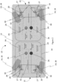
- Figure 1 schematically depicts an autonomous vehicle 10, which typically comprises a body 12 having a passenger compartment for transporting passengers.
- the vehicle 10 comprises at least four wheels 14, each supporting a different end and a different side of the body as well as a steering system 16 for steering steerable wheels 18.
- a command to steer the autonomous vehicle 10 may either come from a main vehicle controller which either detects that steering is required, or which uses a memorized path and sends a command to steer accordingly.
- the autonomous vehicle 10 could be remote controlled and receive the steering command remotely.
- the steering system 16 of the instant embodiment steers two steerable wheels 18 through two actuators 20.
- Each actuator 20 is connected at one end to the body 12 and at its moveable end to a different one of the steerable wheels 18.
- the steerable wheels 18 are solely located at a front 21 of the vehicle 10.
- the wheels 14 located at a back 22 of the vehicle 10 are non-steerable. It should be noted that the front 21 and the back 22 of the vehicle 10 could be inverted.
- Steerable wheels 18 are typically organized in pairs on a common "axle". Although there is clearly no axle used in the present embodiment, that term will nevertheless be used to denote two corresponding wheels located at a common longitudinal distance in the vehicle 10, but on two different sides of the vehicle 10.
- Each actuator 20 is independently controlled by a controller 24 and independently powered by its own power source 26.
- the actuators 20 may either be hydraulic, in which case the power source 26 is a hydraulic pump, or electro-mechanic, in which case the power source 26 is electric.
- the actuators 20 may be linear or rotational. In case of failure, each actuator 20 may be back driven.
- each controller 24 independently connected to one actuator 20 is operative to send a signal to its respective actuator 20 that is indicative of a stroke to reach. In turn, this stroke corresponds to a desired steering angle of that steerable wheel 18.
- the controller 24 therefore sends a signal to the actuator 20 to which it is connected that is proportional to the desired steering angle.
- Each actuator 20 may be equipped with its own stroke sensor 27 operative to send back a signal (a stroke reading) to its controller 24, indicative of the stroke it has reached. This creates a feedback loop allowing the controller 24 to readjust its command in case the actuator 20 has not reached the desired stroke.
- angle sensors 28 may be installed in proximity to a steering pivot 30 of each steerable wheel 18 to monitor the actual steering angle of its respective steerable wheel 18. Typically, each angle sensor 28 also feeds its actual steering angle reading to its respective controller for monitoring. If the controller 24 detects a significant discrepancy between the actual angle reading and a theoretical angle yielded by the stroke read by the stroke sensor 27, then the controller 24 may decide on a mitigating action, such as switching the actuator 20 in passive mode, or stopping the vehicle by communicating a request to the main vehicle controller.
- the expression "controlling in Passive mode” shall be interpreted as switching one actuator in Passive mode, that is letting this actuator being back-driven.
- the one or many controllers 24 may be of the high-integrity type. High integrity types of controllers 24 further add to the integrity of the whole system.
- redundancy is provided by a steering link 32 connecting both steerable wheels 18. It is used as a redundant steering means in case one of the actuators 20 fails. Because each steerable wheel 18 is independently controlled, their steering angle may be slightly different. However, in normal operation, this steering angle will follow the Ackermann principle so an Ackermann geometry may be built in the steering link 32. According to the Ackermann geometry, in a turn, the inner wheel steers more than the outer wheel.
- the steering link 32 comprises a steering rod and two steering arms, one connected to each steerable wheel 18. In other cases, however, and as will be further discussed below, it may be desirable for the steered wheels 18 to acquire a parallel toe angle.
- the steering link 32 is designed with free play so that the steered wheels 18 may steer either parallel to each other or with an Ackermann angle in between them. This free play insures a certain independence of steering of the corresponding steered wheels 18 on a common axle. If one of the actuators 20 fails, the steered wheel 18 on the failed side may want to steer in a totally unpredictable manner. To prevent this, a predetermined threshold of angle difference between both steerable wheels 18 of a common axle is designed in the steering link 32. This predetermined threshold may correspond to the end of the free play in the steering linkage. Passed this threshold, the steering link 32 acts as a solid linkage and couples both steerable wheels 18.
- the steering link 32 may be equipped with one or both of a resilient spring element and a damping element.
- the steering link 32 may either be a mechanical link or a hydraulic connection between the steerable wheels 18.
- a pneumatic connection could even be considered.
- the steering link 32 could be dualized, that is two steering links 32 may be used in combination to both steer the steerable wheels 18 to which they are attached.
- the steering links 32 may be attached one atop the other or in some appropriate way. They may be concentric rods or placed side-by-side. Under some circumstances, it may even be appropriate to use such dualized steering links 32 and to remove one of the actuators 20 driving one of the steerable wheels 18 to which the steering links 32 are attached.
- the other steering link 32 is still sufficient to transfer steering movement between both steerable wheels 18 to which it is attached. This would however be to the detriment of the integrity of the system since there would be no way to steer the steerable wheels 18 in case of failure of the only remaining actuator 20.
- a second steering system 16 similar to the one used at the front 21 of the vehicle 10, is used at the back 22 of the vehicle.
- This embodiment is depicted in Figure 2 , now concurrently referred to.
- all four wheels 14 of the vehicle 10 are steerable.
- the steerable wheels 18 of the front axle are steered independently, each being steered through their own actuator 20 controlled by their own controller 24.
- the exact same steering system architecture is used at the rear of the vehicle 10 as at the front of the vehicle and works exactly the same way. The rear steering system 16 will therefore not be further described here.
- This four-wheel steering system however provides an advantage over that of the two-wheel steering system: the crabbing capacity (also known as Dog Tracking). Crabbing happens when the vehicle 10 moves sideways at an angle. This maneuver may be induced by steering all wheels 14 at the same angle. This capacity is useful when, for example, the vehicle 10 is required to dock along a platform, for example to embark or disembark passengers.
- the crabbing capacity also known as Dog Tracking
- FIG. 3 A variant of this design still provides some level of redundancy while using less components (and is therefore arguably cheaper to manufacture).
- This embodiment which is not part of the claimed invention, is depicted in Figure 3 , now concurrently referred to.
- This embodiment is similar to the previous embodiment depicted in Figure 2 , except that only two controllers 24 and two power sources 26 are used instead of four of each.
- Each controller 24 is linked to two steered wheels 18 located on the same side of the body 12. Hence, one controller 24a controls the steering of the right steerable wheels 18a by being connected to the right actuators 20a while the other controller 24b controls the steering of the left steerable wheels 18b by being connected to the left actuators 20b.
- Both right stroke sensors 27a are connected to the controller 24a for providing feedback on the stroke of the front right and rear right actuators 20a. Both right angle sensors 28a are also connected to the right controller 24a for providing feedback on the steering angle of the front right and rear right steerable wheels 18a. Similarly, both left stroke sensors 27b are connected to the left controller 24b for providing feedback on the stroke of the front left and rear left actuators 20b. Both left angle sensors 28b are also connected to the left controller 24b for providing feedback on the steering angle of the front left and rear left steerable wheels 18b.
- the right and left controllers 24a, 24b are referred to as such not based on their actual location, but rather because they belong respectively to either the right or the left steering system 16a, 16b.
- the right power source 26a powers both of the right actuators 20a while the left power source 26b powers both of the left actuators 20b.
- the right and left power sources 26a, 26b are referred to as such not based on their actual location, but rather because they belong respectively to either the right or the left steering system 16a, 16b.
- the right and left power sources 26a, 26b may either be hydraulic, in which case the actuators 20 are hydraulic actuators or the right and left power sources 26a, 26b may be electric in which case the actuators 20 are electro-mechanical actuators.
- the steering links 32 belong to either the right or left steering systems 16a, 16b since they still connect the right and left steerable wheels 18 on a common axle.
- the front steering link 32a connects the front right and front left steerable wheels 18 while the rear steering link 32b connects the rear right and rear left steerable wheels 18.
- each steering link 32 could belong to a different one of the steering systems 16a, 16b by having a right steering link 32a connecting the right front steerable wheel 18a to the right rear steerable wheel 18a and a left steering link 32b connecting the left front steerable wheel 18b to the left rear steerable wheel 18b.
- the controllers 24 and the power sources 26 as well as their connections have been omitted to clearly see the steering links 32a, 32b, but that it should be understood that implementations of such controllers 24, power sources 26 and their respective connections may be achieved according to either Figure 2 or Figure 3 .
- the autonomous vehicle 10 of this embodiment comprises four steerable wheels 18 supporting a different end and a different side of the body 12, the steering system 16, four controllers 24 and at least two power sources 26.
- This steering system 16 is made of four sets of actuators 20, each having a first actuator 20c and a second actuator 20d connected in opposition. Each set of actuators 20 is connected to a different one of the four steerable wheels 18.
- the first power source 26c powers all first actuators 20c, while the second power source 26d powers all second actuators 20d.
- these power sources 26c, 26d may be a hydraulic pump, when the actuators 20 used are hydraulic actuators or the power sources 26c, 26d may be an electric power source when the actuators 20 used are electro-mechanical actuators.
- the actuators 20 are controlled to work in Active-Passive mode. Active means that the controller is controlled and provides the force to steer the wheel. Passive means that the actuator is not controlled or is not responsive to the command and is simply back driven by the moveable element to which it is attached. Hence, in Active-Passive mode, one actuator provides a force to steer the wheel while the other is being back driven and provides no force. Active-Active mode means that both controllers provide a force to steer the wheel.
- each one of the four controllers 24 Upon receiving the command from the main vehicle controller, each one of the four controllers 24 controls a steering of a different one of the four steerable wheels 18.
- Each controller 24 is connected in Active mode to the first actuator 20c of the respectively steerable wheel 18 it controls.
- Each controller 24 may additionally be connected in Passive mode to the second actuator 20d of at least one of the other steerable wheels 18. None of the controllers 24 is connected to both the first actuator 20c and the second actuator 20d of one given steerable wheel 18.
- each controller 24 is assigned to the control of a different steerable wheel 18 and controls two actuators 20: one first actuator 20c steering a first steerable wheel 18 is controlled in Active mode and one second actuator 20d connected to a second steerable wheel 18 is controlled in Passive mode. If, for example, a first controller 24 detects a failure of its Actively controlled first actuator 20c (e.g.
- controller 24x controls in Active mode the steering of the front right steerable wheel 18x through the first actuator 20cx. Controller 24x is also connected in Passive mode to the second actuator 20dy of the front left steerable wheel 18y. Controller 24x receives the feedback signals from the stroke sensor 27cx and angle sensor 28x of the steerable wheel 18x as well as from the stroke sensor 27dy and angle sensor 28y of the steerable wheel 18y.
- Controller 24y controls in Active mode the steering of the front left steerable wheel 18y through the first actuator 20cy. Controller 24y is also connected in Passive mode to the second actuator 20dx of the front right steerable wheel 18x. Controller 24y receives the feedback signals from the stroke sensor 27cy and angle sensor 28y of the steerable wheel 18y as well as from the stroke sensor 27dx and angle sensor 28x of the steerable wheel 18x. The control of both front steerable wheels 18x, 18y is therefore interconnected so that one controller 24x, 24y acts as a redundant controller for the other one by controlling the second actuator 20dx, 20dy of the other controller 24y, 24x.
- Controller 24z controls in Active mode the steering of the rear right steerable wheel 18z through the first actuator 20cz. Controller 24z is also connected in Passive mode to the second actuator 20dw of the rear left steerable wheel 18w. Controller 24z receives the feedback signals from the stroke sensor 27cz and angle sensor 28z of the steerable wheel 18z as well as from the stroke sensor 27dw and angle sensor 28w of the steerable wheel 18w.
- Controller 24w controls in Active mode the steering of the rear left steerable wheel 18w through the first actuator 20cw. Controller 24w is also connected in Passive mode to the second actuator 20dz of the rear right steerable wheel 18z. Controller 24w receives the feedback signals from the stroke sensor 27cw and angle sensor 28w of the steerable wheel 18w as well as from the stroke sensor 27dz and angle sensor 28z of the steerable wheel 18z. The control of both rear steerable wheels 18z, 18w is therefore interconnected so that one controller 24z, 24w acts as a redundant controller for the other one by controlling the second actuator 20dz, 20dw of the other controller 24w, 24z.
- interconnections are only provided as an example and the same level of redundancy may be provided by interconnecting a controller 24 in Passive mode with any one of the wheels to which it is not connected to the first actuator 20 in Active mode.
- the controller 24x could be connected to any one of the second actuators 20dy, 20dz or 20dw.
- the other controllers 24y, 24w, 24z must also therefore be connected in Passive mode to any one of the other second actuators 20 so that each steerable wheel 18 is controlled in Active mode by one controller 24 and in Passive mode by another controller 24.
- the actuators may be controlled in Active-Active mode so that both the first actuator 20c and the second actuator 20d attached to the same steerable wheel 18 may use a force to induce a steering movement to the steerable wheel 18.
- the controllers 24 and actuators 20 may be interconnected as previously described, but a force-fight control is added to the controllers 24 so as to prevent having the first and second actuators 20c, 20d of a set of actuators force against each other or forcing differently and creating mechanical fatigue.
- the controllers 24, using a force-fight reduction algorithm are capable of reducing the induced additional force created by a possible misalignment of a set of actuators 20, by either adjusting the stroke of or the force applied by one or both actuators 20 so that the steerable wheel 18 to which the set of actuators 20 is connected is steered at the desired angle without additional force being incurred in the actuators 20.
- This is especially important in the case where the vehicle 10 is a self-propelled electric vehicle which needs to manage properly its battery, which also feeds the power sources 26, in order to maximize its range. Consequently, the following force-fight solution is applied.
- the FFRC sensors 29 are required in the actuators 20.
- the FFRC sensors 29 may detect one or more of a load, force, pressure or current, depending on the type of actuator 20 used.
- the FFRC sensors 29 of both connected first and second actuators 20c, 20d are operative to send the detected signal to both their respective controller 24 as well as to the controller 24 of the other connected actuator.
- the FFRC sensors 29 of both the first and second actuator 20c, 20d send their respective signals to both the controller 24 controlling the first actuator 20c and to the controller 24 controlling the second actuator 20d.
- a force-fight reduction controller 34 which may be implemented in each individual controller 24, implements a so-called force-fight limiting compensation function whose goal is to equalize the load share between all active actuators 20 acting on a given steerable wheel 18 to less than a percentage of the actuator maximum force. Typical numbers range between 10 to 30%.
- a control current command output 36 (such as for commanding an electro-hydraulic servo valve (EHSV) or motor torque for example) of every actuator position controller 38 of actuators 20 which are part of one set of actuators so as to balance the measured loads applied by each active actuator 20 on a given steerable wheel 18.
- EHSV electro-hydraulic servo valve
- the compensation can be considered as being equivalent to a position command bias for aligning the motion and position of any given actuator 20 with that of the other actuator 20 in a set of actuators.
- the force-fight reduction controller 34 provides an adaptive improvement to the sets of actuators 20. In other words, the force-fight reduction controller 34 acts as a continuous mutual recalibration with one another of both actuators 20 of one set of actuators.
- One force-fight reduction controller 34 is associated with every actuator position controller 38 controlling the steering angle of one steerable wheel 18 steered by one set of at least two actuators nominally acting in an All Active configuration. Both the actuator position controller 38 and the force-fight reduction controller 34, for a given actuator 20 or a given set of actuators 20, may be implemented as a pair in their corresponding controller 24.
- the actuator position controller 38 and the force-fight reduction controller 34 may operate at a sampling frequency which typically ranges between 250 and 500 Hz (i.e. 4 ms and 2 ms sampling period, respectively).
- the force-fight reduction controller 34 computes and adds a limited-authority compensation to the control current command 36 computed by the actuator position controller 38.
- the force-fight reduction controller 34 authority is typically limited to approximately +/- 20% of control current command 36, while the combined authority of the actuator position controller 38 and force-fight reduction controller 34 is limited to the nominal value of the control current command.
- the force-fight reduction controller 34 comprises a force-fight enable logic function 40 and a force-fight compensation function 42.
- the force-fight enable logic function 40 determines if the force-fight reduction controller 34 supplies a compensation based on availability of the required actuator sensor data and the status of the force-fight reduction controller 34, while the force-fight compensation function computes the value of this compensation. If failure occurs in either one of the first actuator 20c or second actuator 20d connected to one common steerable wheel 18, then the force-fight reduction control function is disactivated since the failed actuator 20 will have been placed in Passive mode by its controller 24.
Landscapes
- Engineering & Computer Science (AREA)
- Chemical & Material Sciences (AREA)
- Combustion & Propulsion (AREA)
- Transportation (AREA)
- Mechanical Engineering (AREA)
- Steering Control In Accordance With Driving Conditions (AREA)
Claims (6)
- Fahrzeug (10), umfassend:eine Karosserie (12), die einen Fahrgastraum aufweist;vier Lenkungssysteme (16), wobei jedes Lenkungssystem aufweist:ein Rad (14, 18), wobei die Räder der vier Lenkungssysteme (16) ein unterschiedliches Ende und eine unterschiedliche Seite der Karosserie (12) stützen; undein erstes Stellglied (20), das das Rad (14, 18) mit der Karosserie (12) verbindet, um das Rad zu lenken;mindestens zwei Steuereinheiten (24), die betriebsfähig mit den ersten Stellgliedern (20) verbunden sind, um eine Betätigung der ersten Stellglieder (20) zu steuern;eine erste Energiequelle (26), die eine erste Untergruppe der ersten Stellglieder (20) mit Energie versorgt; undeine zweite Energiequelle (26), die eine zweite Untergruppe der ersten Stellglieder (20) mit Energie versorgt,dadurch gekennzeichnet, dass das Fahrzeug (10) ein autonomes Fahrzeug ist, dadurch, dass die mindestens zwei Steuereinheiten (24) vier Steuereinheiten (24) sind, und dadurch, dass jedes der vier Lenkungssysteme (16) ferner umfasst:ein zweites Stellglied (20), das das Rad (14, 18) mit der Karosserie (12) verbindet, um das Rad (14, 18) zu lenken; undeine der vier Steuereinheiten (24), wobei jede Steuereinheit (32) betriebsfähig mit dem ersten Stellglied (20) des jeweiligen Lenkungssystems (16) und mit einem der zweiten Stellglieder (20) eines anderen der Lenkungssysteme (16) verbunden ist;wobei die erste Energiequelle (26) eine erste Untergruppe der zweiten Stellglieder (20) mit Energie versorgt und wobei die zweite Energiequelle (26) eine zweite Untergruppe der zweiten Stellglieder (20) mit Energie versorgt,wobei jedes der zweiten Stellglieder (20) entgegengesetzt zu dem ersten Stellglied (20) des jeweiligen Lenkungssystems auf das jeweilige Rad (14, 18) einwirkt.
- Autonomes Fahrzeug (10) nach Anspruch 1, wobei die ersten und zweiten Stellglieder (20) eins von einem hydraulischen Typ und einem elektromechanischen Typ sind, wobei die erste und zweite Energiequelle (26) Hydraulikpumpen sind, wenn die ersten und zweiten Stellglieder (20) von dem hydraulischen Typ sind, und wobei die erste und zweite Energiequelle (26) elektrische Energiequellen sind, wenn die ersten und zweiten Stellglieder (20) von dem elektromechanischen Typ sind.
- Autonomes Fahrzeug (10) nach einem der Ansprüche 1 bis 2, wobei die vier Steuereinheiten (24) in zwei Paaren organisiert sind, wobei jedes Paar von Steuereinheiten (24) zwei der vier Lenkungssysteme (16) steuert, die sich an einem unterschiedlichen Ende der Karosserie (12) befinden.
- Autonomes Fahrzeug (10) nach einem der Ansprüche 1 bis 3, wobei die Steuereinheit (24) jedes Lenkungssystems (16) ferner im Aktiv-Modus mit dem ersten Stellglied (20) des jeweiligen Lenkungssystems (16) verbunden und im Passiv-Modus mit einem der zweiten Stellglieder (20) eines unterschiedlichen der vier Lenkungssysteme (16) verbunden ist.
- Autonomes Fahrzeug (10) nach einem der Ansprüche 1 bis 4, wobei die ersten Stellglieder (20) und die zweiten Stellglieder (20) jedes Lenkungssystems (16) im Aktiv-Aktiv-Modus arbeiten, wobei jede Steuereinheit (24) jedes Lenkungssystems (16) ferner ein Widerstand-Kompensationssystem umfasst, das angepasst ist, um eines von einem Hub oder einer Kraft mindestens eines der ersten Stellglieder (20) und der zweiten Stellglieder (20) eines jeweiligen der Lenkungssysteme (16) einzustellen.
- Autonomes Fahrzeug (10) nach einem der Ansprüche 1 bis 5, wobei die Steuereinheiten (24) hochzuverlässige Steuereinheiten sind.
Applications Claiming Priority (1)
| Application Number | Priority Date | Filing Date | Title |
|---|---|---|---|
| US201962951414P | 2019-12-20 | 2019-12-20 |
Publications (2)
| Publication Number | Publication Date |
|---|---|
| EP3838718A1 EP3838718A1 (de) | 2021-06-23 |
| EP3838718B1 true EP3838718B1 (de) | 2025-02-19 |
Family
ID=73856426
Family Applications (1)
| Application Number | Title | Priority Date | Filing Date |
|---|---|---|---|
| EP20216107.1A Active EP3838718B1 (de) | 2019-12-20 | 2020-12-21 | Lenkungssystem für ein autonomes fahrzeug |
Country Status (4)
| Country | Link |
|---|---|
| US (1) | US12037058B2 (de) |
| EP (1) | EP3838718B1 (de) |
| CN (1) | CN113002615B (de) |
| CA (2) | CA3099415A1 (de) |
Families Citing this family (4)
| Publication number | Priority date | Publication date | Assignee | Title |
|---|---|---|---|---|
| US12252380B1 (en) | 2018-04-27 | 2025-03-18 | California Manufacturing & Engineering Company, Llc | Work platform having attached movable work step |
| EP4363292A1 (de) * | 2021-06-28 | 2024-05-08 | Volvo Truck Corporation | Verfahren zur steuerung eines lenkbetriebs und lenksystem |
| AU2023212782A1 (en) * | 2022-01-26 | 2024-07-25 | California Manufacturing And Engineering Co., Llc | Mobile elevated work platform vehicles with novel steering system and related methods |
| US20260116468A1 (en) | 2024-10-25 | 2026-04-30 | Avride Inc. | Chassis for robotic vehicle |
Family Cites Families (22)
| Publication number | Priority date | Publication date | Assignee | Title |
|---|---|---|---|---|
| NL126112C (de) | 1960-02-12 | |||
| DE19526250B4 (de) | 1995-07-18 | 2005-02-17 | Daimlerchrysler Ag | Brems- und Lenksystem für ein Fahrzeug |
| JP4140372B2 (ja) * | 2002-12-18 | 2008-08-27 | 日産自動車株式会社 | 多重系車両操舵装置 |
| DE10352494A1 (de) | 2003-11-11 | 2005-06-09 | Robert Bosch Gmbh | Momentensteller für ein Lenksystem in einem Kraftfahrzeug |
| US7434653B2 (en) * | 2005-03-31 | 2008-10-14 | Caterpillar Inc. | On-demand electro-hydraulic steering system |
| KR101726688B1 (ko) * | 2012-06-20 | 2017-04-14 | 한화테크윈 주식회사 | 비상조향 시스템 및 비상조향 시스템의 제어방법 |
| US9452779B2 (en) * | 2012-12-27 | 2016-09-27 | Volvo Truck Corporation | Control method of a power steering system for a vehicle having two steered axles |
| ITTO20130066A1 (it) | 2013-01-28 | 2014-07-29 | Fiat Group Automobiles Spa | Sistema di servosterzo elettrico per un autoveicolo |
| WO2015054760A1 (en) | 2013-10-17 | 2015-04-23 | Volvo Do Brasil Veículos Ltda. | Anti-vibration link for dual steer axle steering linkage |
| KR101539027B1 (ko) * | 2013-12-24 | 2015-07-29 | 한국과학기술원 | 인휠모터 구동 자동차의 조향장치 및 이를 이용한 조향 제어방법 |
| US20160096550A1 (en) * | 2014-04-09 | 2016-04-07 | Matthew W. Dames | Agricultural vehicle with toe angle adjustment |
| US10220836B2 (en) * | 2015-02-19 | 2019-03-05 | Honda Motor Co., Ltd. | Vehicle |
| DE102016204560A1 (de) * | 2016-03-18 | 2017-09-21 | Ford Global Technologies, Llc | Lenksystem für ein lenkbares Fahrzeug |
| US9919736B2 (en) | 2016-03-30 | 2018-03-20 | Nissan North America, Inc. | Vehicle adaptive steering control apparatus |
| US10787192B1 (en) * | 2017-04-11 | 2020-09-29 | Apple Inc. | Steer-by-wire system with multiple steering actuators |
| DE102017208554A1 (de) * | 2017-05-19 | 2018-11-22 | Bayerische Motoren Werke Aktiengesellschaft | Radaufhängung für ein zumindest geringfügig aktiv lenkbares Hinterrad eines zweispurigen Fahrzeugs, Achse mit einer Radaufhängung und Fahrzeug mit einer Radaufhängung |
| CN107650678B (zh) | 2017-09-22 | 2021-08-17 | 清华大学 | 分布式纯电动车的底盘系统 |
| WO2019188951A1 (ja) * | 2018-03-26 | 2019-10-03 | 株式会社ジェイテクト | 制御装置、転舵装置、制御方法及びプログラム |
| DE112018007643T5 (de) | 2018-05-21 | 2021-04-01 | Showa Corporation | Lenkeinrichtung |
| US11952060B2 (en) * | 2018-06-25 | 2024-04-09 | Volvo Truck Corporation | Steering assembly for a vehicle |
| JP7141893B2 (ja) * | 2018-09-04 | 2022-09-26 | 日立Astemo株式会社 | ステアリング装置 |
| TWI790411B (zh) * | 2019-11-22 | 2023-01-21 | 財團法人工業技術研究院 | 轉向裝置及方法 |
-
2020
- 2020-11-17 CA CA3099415A patent/CA3099415A1/en active Pending
- 2020-12-16 CA CA3102738A patent/CA3102738C/en active Active
- 2020-12-17 US US17/124,585 patent/US12037058B2/en active Active
- 2020-12-18 CN CN202011504552.8A patent/CN113002615B/zh active Active
- 2020-12-21 EP EP20216107.1A patent/EP3838718B1/de active Active
Also Published As
| Publication number | Publication date |
|---|---|
| EP3838718A1 (de) | 2021-06-23 |
| CN113002615A (zh) | 2021-06-22 |
| CN113002615B (zh) | 2023-08-18 |
| CA3102738A1 (en) | 2021-02-16 |
| US12037058B2 (en) | 2024-07-16 |
| CA3099415A1 (en) | 2021-02-05 |
| US20210188345A1 (en) | 2021-06-24 |
| CA3102738C (en) | 2022-06-14 |
Similar Documents
| Publication | Publication Date | Title |
|---|---|---|
| CA3102738C (en) | Steering system for an autonomous vehicle | |
| US5313389A (en) | Fail-safe mechanism for vehicle stability augmentation steering system | |
| US6244371B1 (en) | Steering system for non-track-bound motor vehicles | |
| CN116635292A (zh) | 使用制动器、车轮马达速度或推进能量中的至少一个使车辆转向的方法 | |
| US6502661B1 (en) | Steering system for a vehicle | |
| CN109496189B (zh) | 线控转向系统、机动车和用于运行线控转向系统的方法 | |
| US5092419A (en) | All-wheel steering | |
| KR101225276B1 (ko) | 차륜 조향 액츄에이터의 고장의 경우에 저하 작동 모드를포함하는 차량 조향 시스템 | |
| JPH01202577A (ja) | 車両の舵角制御装置 | |
| JPS59128054A (ja) | 車両の4輪転舵装置 | |
| US20250187654A1 (en) | Method for Operating a Steering System of a Vehicle | |
| WO2022185398A1 (en) | Steering system for vehicle | |
| JPH01153383A (ja) | 自動車の四輪操舵装置 | |
| JP4785894B2 (ja) | 能動的ロール制御用のフェイルセーフ弁 | |
| WO2016148112A1 (ja) | 後輪転舵制御システム | |
| US20250074504A1 (en) | An Electro-Hydraulic Steering System and a Method of Controlling an Electro Hydraulic Steering System | |
| US11891117B2 (en) | Steering control system of a multi-unit vehicle | |
| GB2454013A (en) | A road vehicle suspension system | |
| JP6764503B2 (ja) | アクチュエータ制御装置 | |
| JP2007326499A (ja) | 操舵装置 | |
| US20250319922A1 (en) | Hybrid steer-by-wire system | |
| US20250382003A1 (en) | Hydraulic steering system for steering a vehicle with a steering mechanics | |
| JP2009234547A (ja) | 後輪操舵制御装置 | |
| JP5478027B2 (ja) | 後輪転舵装置 | |
| CN115489591A (zh) | 用于机动车的转向齿轮设备 |
Legal Events
| Date | Code | Title | Description |
|---|---|---|---|
| PUAI | Public reference made under article 153(3) epc to a published international application that has entered the european phase |
Free format text: ORIGINAL CODE: 0009012 |
|
| STAA | Information on the status of an ep patent application or granted ep patent |
Free format text: STATUS: REQUEST FOR EXAMINATION WAS MADE |
|
| 17P | Request for examination filed |
Effective date: 20201221 |
|
| AK | Designated contracting states |
Kind code of ref document: A1 Designated state(s): AL AT BE BG CH CY CZ DE DK EE ES FI FR GB GR HR HU IE IS IT LI LT LU LV MC MK MT NL NO PL PT RO RS SE SI SK SM TR |
|
| RAP1 | Party data changed (applicant data changed or rights of an application transferred) |
Owner name: ALSTOM HOLDINGS |
|
| P01 | Opt-out of the competence of the unified patent court (upc) registered |
Effective date: 20230822 |
|
| STAA | Information on the status of an ep patent application or granted ep patent |
Free format text: STATUS: EXAMINATION IS IN PROGRESS |
|
| 17Q | First examination report despatched |
Effective date: 20231002 |
|
| GRAP | Despatch of communication of intention to grant a patent |
Free format text: ORIGINAL CODE: EPIDOSNIGR1 |
|
| STAA | Information on the status of an ep patent application or granted ep patent |
Free format text: STATUS: GRANT OF PATENT IS INTENDED |
|
| INTG | Intention to grant announced |
Effective date: 20241021 |
|
| GRAS | Grant fee paid |
Free format text: ORIGINAL CODE: EPIDOSNIGR3 |
|
| GRAA | (expected) grant |
Free format text: ORIGINAL CODE: 0009210 |
|
| STAA | Information on the status of an ep patent application or granted ep patent |
Free format text: STATUS: THE PATENT HAS BEEN GRANTED |
|
| AK | Designated contracting states |
Kind code of ref document: B1 Designated state(s): AL AT BE BG CH CY CZ DE DK EE ES FI FR GB GR HR HU IE IS IT LI LT LU LV MC MK MT NL NO PL PT RO RS SE SI SK SM TR |
|
| REG | Reference to a national code |
Ref country code: GB Ref legal event code: FG4D |
|
| REG | Reference to a national code |
Ref country code: CH Ref legal event code: EP |
|
| REG | Reference to a national code |
Ref country code: DE Ref legal event code: R096 Ref document number: 602020046260 Country of ref document: DE |
|
| REG | Reference to a national code |
Ref country code: IE Ref legal event code: FG4D |
|
| REG | Reference to a national code |
Ref country code: NL Ref legal event code: MP Effective date: 20250219 |
|
| PG25 | Lapsed in a contracting state [announced via postgrant information from national office to epo] |
Ref country code: RS Free format text: LAPSE BECAUSE OF FAILURE TO SUBMIT A TRANSLATION OF THE DESCRIPTION OR TO PAY THE FEE WITHIN THE PRESCRIBED TIME-LIMIT Effective date: 20250519 |
|
| PG25 | Lapsed in a contracting state [announced via postgrant information from national office to epo] |
Ref country code: FI Free format text: LAPSE BECAUSE OF FAILURE TO SUBMIT A TRANSLATION OF THE DESCRIPTION OR TO PAY THE FEE WITHIN THE PRESCRIBED TIME-LIMIT Effective date: 20250219 |
|
| PG25 | Lapsed in a contracting state [announced via postgrant information from national office to epo] |
Ref country code: PL Free format text: LAPSE BECAUSE OF FAILURE TO SUBMIT A TRANSLATION OF THE DESCRIPTION OR TO PAY THE FEE WITHIN THE PRESCRIBED TIME-LIMIT Effective date: 20250219 |
|
| PG25 | Lapsed in a contracting state [announced via postgrant information from national office to epo] |
Ref country code: ES Free format text: LAPSE BECAUSE OF FAILURE TO SUBMIT A TRANSLATION OF THE DESCRIPTION OR TO PAY THE FEE WITHIN THE PRESCRIBED TIME-LIMIT Effective date: 20250219 |
|
| REG | Reference to a national code |
Ref country code: LT Ref legal event code: MG9D |
|
| PG25 | Lapsed in a contracting state [announced via postgrant information from national office to epo] |
Ref country code: NO Free format text: LAPSE BECAUSE OF FAILURE TO SUBMIT A TRANSLATION OF THE DESCRIPTION OR TO PAY THE FEE WITHIN THE PRESCRIBED TIME-LIMIT Effective date: 20250519 Ref country code: IS Free format text: LAPSE BECAUSE OF FAILURE TO SUBMIT A TRANSLATION OF THE DESCRIPTION OR TO PAY THE FEE WITHIN THE PRESCRIBED TIME-LIMIT Effective date: 20250619 |
|
| PG25 | Lapsed in a contracting state [announced via postgrant information from national office to epo] |
Ref country code: NL Free format text: LAPSE BECAUSE OF FAILURE TO SUBMIT A TRANSLATION OF THE DESCRIPTION OR TO PAY THE FEE WITHIN THE PRESCRIBED TIME-LIMIT Effective date: 20250219 |
|
| PG25 | Lapsed in a contracting state [announced via postgrant information from national office to epo] |
Ref country code: HR Free format text: LAPSE BECAUSE OF FAILURE TO SUBMIT A TRANSLATION OF THE DESCRIPTION OR TO PAY THE FEE WITHIN THE PRESCRIBED TIME-LIMIT Effective date: 20250219 |
|
| PG25 | Lapsed in a contracting state [announced via postgrant information from national office to epo] |
Ref country code: PT Free format text: LAPSE BECAUSE OF FAILURE TO SUBMIT A TRANSLATION OF THE DESCRIPTION OR TO PAY THE FEE WITHIN THE PRESCRIBED TIME-LIMIT Effective date: 20250620 Ref country code: LV Free format text: LAPSE BECAUSE OF FAILURE TO SUBMIT A TRANSLATION OF THE DESCRIPTION OR TO PAY THE FEE WITHIN THE PRESCRIBED TIME-LIMIT Effective date: 20250219 |
|
| PG25 | Lapsed in a contracting state [announced via postgrant information from national office to epo] |
Ref country code: GR Free format text: LAPSE BECAUSE OF FAILURE TO SUBMIT A TRANSLATION OF THE DESCRIPTION OR TO PAY THE FEE WITHIN THE PRESCRIBED TIME-LIMIT Effective date: 20250520 Ref country code: BG Free format text: LAPSE BECAUSE OF FAILURE TO SUBMIT A TRANSLATION OF THE DESCRIPTION OR TO PAY THE FEE WITHIN THE PRESCRIBED TIME-LIMIT Effective date: 20250219 |
|
| REG | Reference to a national code |
Ref country code: AT Ref legal event code: MK05 Ref document number: 1768054 Country of ref document: AT Kind code of ref document: T Effective date: 20250219 |
|
| PG25 | Lapsed in a contracting state [announced via postgrant information from national office to epo] |
Ref country code: SE Free format text: LAPSE BECAUSE OF FAILURE TO SUBMIT A TRANSLATION OF THE DESCRIPTION OR TO PAY THE FEE WITHIN THE PRESCRIBED TIME-LIMIT Effective date: 20250219 |
|
| PG25 | Lapsed in a contracting state [announced via postgrant information from national office to epo] |
Ref country code: SM Free format text: LAPSE BECAUSE OF FAILURE TO SUBMIT A TRANSLATION OF THE DESCRIPTION OR TO PAY THE FEE WITHIN THE PRESCRIBED TIME-LIMIT Effective date: 20250219 |
|
| PG25 | Lapsed in a contracting state [announced via postgrant information from national office to epo] |
Ref country code: DK Free format text: LAPSE BECAUSE OF FAILURE TO SUBMIT A TRANSLATION OF THE DESCRIPTION OR TO PAY THE FEE WITHIN THE PRESCRIBED TIME-LIMIT Effective date: 20250219 |
|
| PG25 | Lapsed in a contracting state [announced via postgrant information from national office to epo] |
Ref country code: IT Free format text: LAPSE BECAUSE OF FAILURE TO SUBMIT A TRANSLATION OF THE DESCRIPTION OR TO PAY THE FEE WITHIN THE PRESCRIBED TIME-LIMIT Effective date: 20250219 |
|
| PG25 | Lapsed in a contracting state [announced via postgrant information from national office to epo] |
Ref country code: AT Free format text: LAPSE BECAUSE OF FAILURE TO SUBMIT A TRANSLATION OF THE DESCRIPTION OR TO PAY THE FEE WITHIN THE PRESCRIBED TIME-LIMIT Effective date: 20250219 |
|
| PG25 | Lapsed in a contracting state [announced via postgrant information from national office to epo] |
Ref country code: EE Free format text: LAPSE BECAUSE OF FAILURE TO SUBMIT A TRANSLATION OF THE DESCRIPTION OR TO PAY THE FEE WITHIN THE PRESCRIBED TIME-LIMIT Effective date: 20250219 Ref country code: CZ Free format text: LAPSE BECAUSE OF FAILURE TO SUBMIT A TRANSLATION OF THE DESCRIPTION OR TO PAY THE FEE WITHIN THE PRESCRIBED TIME-LIMIT Effective date: 20250219 |
|
| PG25 | Lapsed in a contracting state [announced via postgrant information from national office to epo] |
Ref country code: RO Free format text: LAPSE BECAUSE OF FAILURE TO SUBMIT A TRANSLATION OF THE DESCRIPTION OR TO PAY THE FEE WITHIN THE PRESCRIBED TIME-LIMIT Effective date: 20250219 |
|
| PG25 | Lapsed in a contracting state [announced via postgrant information from national office to epo] |
Ref country code: SK Free format text: LAPSE BECAUSE OF FAILURE TO SUBMIT A TRANSLATION OF THE DESCRIPTION OR TO PAY THE FEE WITHIN THE PRESCRIBED TIME-LIMIT Effective date: 20250219 |
|
| REG | Reference to a national code |
Ref country code: DE Ref legal event code: R097 Ref document number: 602020046260 Country of ref document: DE |
|
| PLBE | No opposition filed within time limit |
Free format text: ORIGINAL CODE: 0009261 |
|
| STAA | Information on the status of an ep patent application or granted ep patent |
Free format text: STATUS: NO OPPOSITION FILED WITHIN TIME LIMIT |
|
| 26N | No opposition filed |
Effective date: 20251120 |