EP3838629A1 - Fahrzeugluftreifen aufweisend eine oberflächenkontraststruktur mit stegen - Google Patents
Fahrzeugluftreifen aufweisend eine oberflächenkontraststruktur mit stegen Download PDFInfo
- Publication number
- EP3838629A1 EP3838629A1 EP20204263.6A EP20204263A EP3838629A1 EP 3838629 A1 EP3838629 A1 EP 3838629A1 EP 20204263 A EP20204263 A EP 20204263A EP 3838629 A1 EP3838629 A1 EP 3838629A1
- Authority
- EP
- European Patent Office
- Prior art keywords
- web
- vehicle tire
- height
- webs
- contrast structure
- Prior art date
- Legal status (The legal status is an assumption and is not a legal conclusion. Google has not performed a legal analysis and makes no representation as to the accuracy of the status listed.)
- Granted
Links
Images

Classifications
-
- B—PERFORMING OPERATIONS; TRANSPORTING
- B60—VEHICLES IN GENERAL
- B60C—VEHICLE TYRES; TYRE INFLATION; TYRE CHANGING; CONNECTING VALVES TO INFLATABLE ELASTIC BODIES IN GENERAL; DEVICES OR ARRANGEMENTS RELATED TO TYRES
- B60C13/00—Tyre sidewalls; Protecting, decorating, marking, or the like, thereof
- B60C13/001—Decorating, marking or the like
-
- B—PERFORMING OPERATIONS; TRANSPORTING
- B29—WORKING OF PLASTICS; WORKING OF SUBSTANCES IN A PLASTIC STATE IN GENERAL
- B29D—PRODUCING PARTICULAR ARTICLES FROM PLASTICS OR FROM SUBSTANCES IN A PLASTIC STATE
- B29D30/00—Producing pneumatic or solid tyres or parts thereof
- B29D30/06—Pneumatic tyres or parts thereof (e.g. produced by casting, moulding, compression moulding, injection moulding, centrifugal casting)
- B29D30/0601—Vulcanising tyres; Vulcanising presses for tyres
- B29D30/0606—Vulcanising moulds not integral with vulcanising presses
-
- B—PERFORMING OPERATIONS; TRANSPORTING
- B29—WORKING OF PLASTICS; WORKING OF SUBSTANCES IN A PLASTIC STATE IN GENERAL
- B29D—PRODUCING PARTICULAR ARTICLES FROM PLASTICS OR FROM SUBSTANCES IN A PLASTIC STATE
- B29D30/00—Producing pneumatic or solid tyres or parts thereof
- B29D30/06—Pneumatic tyres or parts thereof (e.g. produced by casting, moulding, compression moulding, injection moulding, centrifugal casting)
- B29D30/72—Side-walls
-
- B—PERFORMING OPERATIONS; TRANSPORTING
- B29—WORKING OF PLASTICS; WORKING OF SUBSTANCES IN A PLASTIC STATE IN GENERAL
- B29D—PRODUCING PARTICULAR ARTICLES FROM PLASTICS OR FROM SUBSTANCES IN A PLASTIC STATE
- B29D30/00—Producing pneumatic or solid tyres or parts thereof
- B29D30/06—Pneumatic tyres or parts thereof (e.g. produced by casting, moulding, compression moulding, injection moulding, centrifugal casting)
- B29D30/0601—Vulcanising tyres; Vulcanising presses for tyres
- B29D30/0606—Vulcanising moulds not integral with vulcanising presses
- B29D2030/0607—Constructional features of the moulds
- B29D2030/0612—Means for forming recesses or protrusions in the tyres, e.g. grooves or ribs, to create the tread or sidewalls patterns
-
- B—PERFORMING OPERATIONS; TRANSPORTING
- B29—WORKING OF PLASTICS; WORKING OF SUBSTANCES IN A PLASTIC STATE IN GENERAL
- B29D—PRODUCING PARTICULAR ARTICLES FROM PLASTICS OR FROM SUBSTANCES IN A PLASTIC STATE
- B29D30/00—Producing pneumatic or solid tyres or parts thereof
- B29D30/06—Pneumatic tyres or parts thereof (e.g. produced by casting, moulding, compression moulding, injection moulding, centrifugal casting)
- B29D30/72—Side-walls
- B29D2030/726—Decorating or marking the sidewalls before tyre vulcanization
-
- B—PERFORMING OPERATIONS; TRANSPORTING
- B60—VEHICLES IN GENERAL
- B60C—VEHICLE TYRES; TYRE INFLATION; TYRE CHANGING; CONNECTING VALVES TO INFLATABLE ELASTIC BODIES IN GENERAL; DEVICES OR ARRANGEMENTS RELATED TO TYRES
- B60C11/00—Tyre tread bands; Tread patterns; Anti-skid inserts
- B60C11/03—Tread patterns
- B60C11/0327—Tread patterns characterised by special properties of the tread pattern
-
- B—PERFORMING OPERATIONS; TRANSPORTING
- B60—VEHICLES IN GENERAL
- B60C—VEHICLE TYRES; TYRE INFLATION; TYRE CHANGING; CONNECTING VALVES TO INFLATABLE ELASTIC BODIES IN GENERAL; DEVICES OR ARRANGEMENTS RELATED TO TYRES
- B60C13/00—Tyre sidewalls; Protecting, decorating, marking, or the like, thereof
- B60C13/02—Arrangement of grooves or ribs
Definitions
- the invention relates to a vehicle tire with at least one surface element formed on an outer surface of the vehicle tire, in particular an outer side wall surface and / or an outer tread surface, with a surface contrast structure with webs arranged next to one another.
- the invention also relates to a method for producing such a tire.
- a marking can include graphic elements such as images, characters, company names, company logos, markings, areas, etc.
- the surface element having the contrast structure can be part of the marking and / or completely or partially surround it.
- Such a contrast structure usually has elevations and / or depressions.
- the scattering of light on the flanks of the elevations or depressions reduces the reflection of the light on the surface of the tire, as a result of which the brightness effect is changed.
- surface areas provided with elevations or depressions appear darker than essentially smooth surface areas free of such elevations.
- Such surface elements having a contrast structure are generally embossed in the tire in the course of the vulcanization of the tire by means of a shaping vulcanization mold having a negative contour of the contrast structure.
- a surface with a contrast structure of an already vulcanized tire can also be achieved by removal, e.g. by means of engraving, or by an additive process.
- a pneumatic vehicle tire which has a contrasting structure on its outer surface consisting of a large number of elongated or fiber-like elevations for a high-contrast surface design.
- a pneumatic vehicle tire which has a contrast structure on its outer surface comprising a plurality of depressions for a high-contrast surface design.
- the task is therefore to influence the contrast effect even more specifically and to enable a decrease in contrast within the surface element.
- the contrast effect or the dark effect of the surface contrast structure along the longitudinal extent of the at least one first Web can be reduced in a targeted manner and thus a continuous decrease in contrast along the elongate extent of the at least one first web can be achieved.
- the contrast effect can thus be influenced in an even more targeted manner and a continuous decrease in contrast within the surface element is enabled.
- the at least one first web can extend outwardly from a base and end in a ridge.
- the ridge can be pointed or rounded or flattened or designed with a different shape.
- the height of the at least one first web can be measured from a height level of the base to a height level of the ridge.
- the height can be measured perpendicular to a surface level of the outer surface of the tire.
- the surface level in the area of the sidewall outer surface and the tread can be given by the outer contour of the tire without additional elements such as decorative elements, characters, the surface contrast structure, protective ribs, etc.
- the height can alternatively be measured perpendicular to the height level of the ridge or to the height level of the base. The height is preferably measured perpendicular to the surface level.
- a height level of the ridge and / or a height level of the base of the at least one first web can have irregularities along the elongated extension of the web, in particular as a result of production.
- the height level of the ridge and / or the height level of the base can then each correspond to a mean height level.
- the height of the at least one first web decreases along its elongated extent by a total of at least 60%, preferably by at least 80%, particularly preferably by 100%.
- a particularly clear contrast curve can be achieved by reducing the height along the elongated extent of the at least one first web by a total of at least 60%.
- the decrease in contrast is particularly noticeable when the height along the longitudinal extent of the at least one first web decreases by a total of at least 80%. If the height decreases by a total of 100%, the at least one first web has no height at one end of its elongated extent.
- the surface contrast structure can then correspond to an outer surface of the tire that is free of the surface contrast structure, in particular a smooth, outer surface. The surface contrast structure can then largely no longer have any contrast there with the smooth outer surface of the tire.
- a further advantageous embodiment is given by the fact that the height of the at least one first web decreases along its elongate extent with a constant gradient. A decrease in height with a constant slope causes a particularly uniform decrease in contrast.
- a further advantageous embodiment is given by the fact that the height of the at least one first web decreases along its elongated extent with a gradient of 0.6 ° to 3.5 °. This also makes it possible to achieve an advantageous contrast curve.
- a ridge of the at least one first web running along the elongated extent of the at least one first web is set back inwardly in whole or in part with respect to a surface level of the outer surface of the tire.
- a further advantageous embodiment is given that a distance between a ridge running along the elongated extent of the at least one first web and a surface level of the outer surface of the tire decreases in the direction of the decrease in the height of the at least one first web.
- the height level of the outer surface of the at least one first web matches the surface level of the outer surface in the direction of the decrease in height. This further increases the decrease in contrast in this direction.
- the distance can be measured perpendicular to the surface level.
- the ridge is preferably completely or partially set back inward with respect to the surface level. It is useful if the ridge is set back in the region of the maximum height of the at least one first web by the distance 0.1 to 0.3 mm, preferably 0.2 mm, and / or if the ridge is in the region of a minimum height of the at least one first web is set back by the distance 0 mm to 0.1 mm, preferably 0.05 mm.
- the elongate extension of the at least one first web has an at least partially straight and / or at least partially curved, in particular curved, course.
- the straight and / or curved course can be determined in the plan view of the outer surface. If the outer surface is the side wall outer surface, the plan view can take place in the axial direction. If the outer surface is the running surface or a groove base, the top view can be in the radial direction.
- the at least one first web can be designed to be straight or curved over its entire longitudinal extent.
- the at least one first web can, however, also be designed to be only partially straight and / or only partially curved. In the case of a curved design of the at least one first web, what is known as arc hatching can be involved.
- the maximum height of the at least one first web is 0.1 mm to 0.7 mm, preferably 0.2 mm to 0.5 mm, particularly preferably 0.3 mm. Such a maximum height of the at least one first web enables a sufficient change in the height of the at least one first web for an advantageous contrast difference.
- the webs of the surface contrast structure arranged next to one another have a repeat spacing of 0.2 mm to 1.2 mm, preferably 0.4 mm to 0.7 mm, particularly preferably 0.5 mm to 0.6 mm.
- Such a repetition spacing often also called pitch, enables an advantageous contrast effect of the surface element to be achieved.
- the webs each have opposite lateral flanks which enclose an angle of 5 ° to 60 ° with one another.
- Such steep flanks are advantageous for a particularly strong contrast effect and allow a small repetition distance. This enables a strong change in contrast.
- the surface contrast structure is arranged on an outer side wall surface of the vehicle pneumatic tire and that the webs in their elongated extension form an angle of -45 ° to 45 °, preferably -30 ° to 30 °, particularly preferably approximately 0 °, include with a radial direction rR. This results in an advantageous change in contrast from radially inside to radially outside.
- the surface contrast structure is interrupted by at least one graphic element that is free from such a surface contrast structure, and that the surface contrast structure surrounds the graphic element.
- the graphic element can in particular be a polygon or a letter.
- a particularly good contrast effect between the surface contrast structure and the graphic element results when the structure of the surface of the graphic element corresponds to the outer surface. It is also expedient if a height level of the surface of the graphic element corresponds to the surface level of the outer surface of the tire.
- One or more of the bars in particular one or more of the first bars, can be interrupted by the graphic element.
- the webs can run outside the interruption through the graphic element as if they were free from an interruption.
- the surface element is arranged on the side wall outer surface and / or the tread outer surface, preferably on a side wall outer surface.
- the surface element is formed on one of the side wall outer surfaces of the vehicle tire.
- the surface element is formed on an outer tread surface of the pneumatic vehicle tire.
- the surface element can in particular also be attached to the groove flanks and / or groove bottoms of grooves running in the tread or to the tread that comes into contact with the ground.
- It can be a tire for a passenger car, for a motorcycle, a bicycle or for a utility vehicle.
- the invention also relates to a method for producing a vehicle tire according to at least one of the preceding claims, characterized in that the vehicle tire is vulcanized in a shaping manner by means of a vulcanization mold having a molding surface, the molding surface having a negative contour of the surface contrast structure.
- a tire according to the invention can be produced in a simple manner.
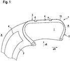
- the Figure 1 shows a pneumatic vehicle tire 1 with at least one surface element 4 with a surface contrast structure 5 formed on an outer surface 2, 3 of the vehicle tire 1, in particular an outer side wall surface 2 and / or an outer tread surface 3 be attached to groove flanks and / or groove bases of grooves running in the tread or on the tread that comes into contact with the ground.
- the surface contrast structure 5 has webs 6 arranged next to one another.
- a height 7 of at least one first web 6 of the webs decreases continuously along the longitudinal extent of the at least one first web 6.
- the height 7 can decrease along the elongated extent of the at least one first web 6 by a total of at least 60%, preferably by at least 80%, particularly preferably by 100%.
- At least 50% of the webs 6, preferably all of the webs 6, of the surface contrast structure 5 can be designed as first webs 6. In this case, all of the first webs 6 can decrease in the same direction 11 along their longitudinal extension at the height 7.
- the webs 6 of the surface contrast structure 5 arranged next to one another can have a repetition spacing 16 of 0.2 mm to 1.2 mm, preferably 0.4 mm to 0.7 mm, particularly preferably 0.5 mm to 0.6 mm.
- the juxtaposed webs 6 of the surface contrast structure 5 can each have opposite lateral flanks 17 which enclose an angle 18 of 5 ° to 60 ° with one another.
- the surface contrast structure 5 can be interrupted by at least one graphic element 19 which is free of such a surface contrast structure 5, the surface contrast structure 5 surrounding the graphic element.
- the Fig. 2 shows a view of an embodiment of a suitable first web 6 designed in this way.
- the first web 6 extends from a base 9 pointing outwards A and ends in a ridge 10.
- the ridge 10 can be pointed or rounded or flattened or with a cross-section of the web other shape. In the Fig. 2 the ridge 10 is shown flattened.
- the height 7 of the first web 6 can drop along the longitudinal extension of the web 6 by a total of at least 60%, preferably by at least 80%, particularly preferably by 100%.
- the height 7 decreases along the direction 11.
- the height 7 of the first web 6 can be measured from a height level 14 of the base 9 to a height level 12 of the ridge 10.
- the height 7 can be measured perpendicular to a surface level 13 of the outer surface of the tire.
- the surface level can be given by the outer contour of the tire without additional elements such as decorative elements, characters, the surface contrast structure, protective ribs, etc.
- the height 7 can alternatively be measured perpendicular to the height level 12 of the ridge or to the height level 14 of the base.
- the height 7 is preferred, as in FIG Fig. 2 shown, measured perpendicular to the surface level 13.
- the maximum height 15 of the first web 6 can be 0.1 mm to 0.7 mm, preferably 0.2 mm to 0.5 mm, particularly preferably 0.3 mm.
- the decrease in the height 7 of the first web 6 can take place with a constant slope.
- the decrease in the height 7 of the first web 6 can take place with a slope of 0.6 ° to 3.5 °.
- the distance 20 of the ridge 10 to the surface level 13 of the outer surface 2, 3 of the tire 1 can decrease in the direction 11 of the decrease in the height 7 of the respective first web 6.
- the ridge 10 of the first web 6 running along the longitudinal extension of the first web 6 is preferably set back inwardly I with respect to the surface level 13 of the outer surface 2, 3 of the tire 1.
- the Fig. 3 shows a plan view of a detail of a sidewall outer surface 2 of a tire 1 according to the invention in the axial direction. having a surface element 4 having a surface contrast structure 5. It can be the tire of the Fig. 1 and / or the surface contrast structure 5 described there.
- the ridge 10 of the at least one first web 6 running along the elongated extension of the at least one first web 6 can be set back inwardly I in whole or in part with respect to a surface level 13 of the outer surface 2, 3 of the tire 1.
- a distance 20 between the ridge 10 and a surface level 13 of the outer surface 2, 3 of the tire 1 also decreases in the direction 11 of the decrease in the height 7 of the at least one first web 6.
- the surface contrast structure 5 can be interrupted by at least one graphic element 22 which is free of such a surface contrast structure 5, the surface contrast structure 5 surrounding the graphic element.
- the surface contrast structure 5 can, however, also be designed free from an interruption.
- At least 50% of the webs 6, preferably all of the webs 6, of the surface contrast structure 5 can be designed as the first web 6. Examples are in the Fig. 3 all of the webs shown are designed as first webs 6. The first webs 6 of the surface contrast structure decrease in the same direction 11 along their elongated extent at the height 7, see Fig. 4 or 5 .
- the Fig. 3 shows webs 6 arranged next to one another, which according to the view in FIG Fig. 2 have a distance from the respectively adjacent web 6 and a flattened ridge 10.
- the bases 10 of the webs can, however, also touch and / or the cross section, in particular in the area of the ridge 10, of the webs 6 can have a different geometry.
- the webs 6 of the surface contrast structure 5 arranged next to one another can have a repetition spacing 16 of 0.2 mm to 1.2 mm, preferably 0.4 mm to 0.7 mm, particularly preferably 0.5 mm to 0.6 mm.
- the webs 6 of the surface contrast structure 5, which are arranged next to one another, can each have opposite lateral flanks 17 which form an angle 18 [see FIG Fig. 2 ] from 5 ° to 60 ° with each other.
- a surface element 4 with a corresponding surface contrast structure 5 can also be arranged on the tread outer surface 3 and / or at another location on the sidewall outer surface 2 of a tire 1 according to the invention.
- the webs 6 as in FIG Fig. 3 shown in their elongated extent enclose an angle 19 of -45 ° to 45 °, preferably -30 ° to 30 °, particularly preferably approximately 0 °, with a radial direction rR.
- the height 7 can decrease from radially inside to radially outside, see the exemplary embodiment in FIG Fig. 5 .
- the height 7 can also, as for another exemplary embodiment in FIG Figure 4 shown, remove from the radial outside to the radial inside.
- the elongate extension of the at least one first web 6 is straight.
- the elongated extension of the at least one first web 6 can, however, also be completely or partially curved, in particular curved in an arc shape. Adjacent webs 6 can thus result in curved hatching.
- the straight and / or curved course can be determined in the plan view in the axial direction of the outer surfaces 2.
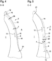
- FIGS. 4 and 5 each show a cross section of the Fig. 3
- the tire sidewall shown along the ridges 10 of the first webs 6.
- the ridges 10 of the two first webs 6 are set back inwardly I with respect to a surface level 13 of the outer surface 2, 3 of the tire 1.
- the maximum height 15 of the first webs 6 is 0.1 mm to 0.7 mm, preferably 0.2 mm to 0.5 mm, particularly preferably 0.3 mm.
- the ridge 10 is set back in the region of the maximum height 15 of the first web 6 by the distance 0.1 to 0.3 mm, preferably 0.2 mm, and / or if the ridge 10 is in the region of a minimum
- the height of the first web is set back by the distance 21 0 mm to 0.1 mm, preferably 0.05 mm.
- the Fig. 4 shows a section along the line BB, the first web 6 being free from an interruption.
- the direction 11 of the decrease in height 7 runs from radially outside to radially inside.
- the distance 20 of the ridge 10 to the surface level 13 of the outer surface 2 of the Tire 1 decreases in a direction 11 of the decrease in height 7 of the respective first web 6.
- the Fig. 5 illustrates an embodiment of the surface contrast structure 5 of FIG Figure 3 , in which the direction 11 of the decrease in height 7 from radially inside to radially outside.
- the Fig. 5 shows a section along the line CC, the web 6 being interrupted by a graphic element 22.
- the structure of the outer surface 23 of the graphic element 22 can correspond to the structure of the outer surface 2.
- the height level of the outer surface 23 of the graphic element 22 can correspond to the surface level 13 of the outer surface of the tire 1.
- the web can run outside the interruption through the graphic element 22 as if it were free of an interruption.
- the tires according to the invention shown in the figures can be produced by a shaping vulcanization process, the vehicle tire 1 being vulcanized in a shaping manner by means of a vulcanization mold having a molding surface, the molding surface having a negative contour of the surface contrast structure 5.
Landscapes
- Engineering & Computer Science (AREA)
- Mechanical Engineering (AREA)
- Tires In General (AREA)
Abstract
Description
- Die Erfindung betrifft einen Fahrzeugreifen mit zumindest einem auf einer Außenfläche des Fahrzeugreifens, insbesondere einer Seitenwandaußenfläche und/oder einer Laufstreifenaußenfläche, ausgebildeten Flächenelement mit einer Oberflächenkontraststruktur mit nebeneinander angeordneten Stegen. Weiter betrifft die Erfindung ein Verfahren zu Herstellung eines solchen Reifens.
- Es ist bekannt, auf der Außenfläche von Fahrzeugluftreifen, insbesondere auf einer Seitenwandaußenfläche und/oder einer Laufstreifenaußenfläche, Flächenelemente mit einer Kontraststruktur auszubilden, welche vorrangig die Aufgabe haben, einen Kontrast zu anderen, insbesondere zu unstrukturierten, Flächenbereichen der Seitenwände und/oder des Laufstreifens zu schaffen, um derart die Erkennbarkeit von auf der Seitenwandaußenfläche und/oder dem Laufstreifen befindlichen Markierungen zu verbessern. Eine Markierung kann dabei graphische Elemente wie Abbildungen, Schriftzeichen, Firmennamen, Firmenlogos, Kennzeichnungen, Flächen, etc. umfassen. Das Flächenelement aufweisend die Kontraststruktur kann dabei Teil der Markierung sein und/oder diese ganz oder teilweise umgeben.
- Eine solche Kontraststruktur weist in der Regel Erhebungen und/oder Vertiefungen auf. Die Streuung von Licht an den Flanken der Erhebungen oder Vertiefungen verringert die Reflektion des Lichts an der Oberfläche des Reifens, wodurch die Helligkeitswirkung verändert ist. In der Regel wirken dabei mit Erhebungen oder Vertiefungen versehene Oberflächenbereiche dunkler als im Wesentlichen glatte, von derartigen Erhebungen freie, Oberflächenbereiche. Somit ist ein Kontrast in der an sich monochromen Oberfläche des Reifens, insbesondere der Seitenwandaußenfläche und/oder der Laufstreifenaußenfläche, ermöglicht. Hierdurch können Darstellungen von Markierungen verbessert sichtbar gemacht werden.
- Derartige Flächenelemente aufweisend eine Kontraststruktur werden in der Regel im Zuge der Vulkanisation des Reifens mittels einer formgebenden eine Negativkontur der Kontraststruktur aufweisenden Vulkanisationsform in den Reifen geprägt. Eine Oberfläche aufweisend eine Kontraststruktur eines bereits vulkanisierten Reifens kann aber auch durch Abtragung, z.B. mittels Gravur, oder durch ein additives Verfahren erreicht werden.
- Bekannt ist beispielsweise aus der
US 2012/0227879 A1 ein Fahrzeugluftreifen, der auf seiner äußeren Oberfläche eine Kontraststruktur aus einer Vielzahl von länglichen oder faserartigen Erhebungen zur kontrastreichen Oberflächengestaltung aufweist. Aus derWO 2014 040 967 A1 ist ein Fahrzeugluftreifen bekannt, der auf seiner äußeren Oberfläche eine Kontraststruktur aus einer Vielzahl von Vertiefungen zur kontrastreichen Oberflächengestaltung aufweist. - Nachteilig an derartigen Ausführungsformen ist, dass die Gestaltungsmöglichkeiten gering sind. Insbesondere für die Darstellung von graphischen Elementen ist es aber von Vorteil, den Kontrast variabel einzustellen.
- Aufgabe ist es daher, die Kontrastwirkung noch gezielter zu beeinflussen und eine Kontrastabnahme innerhalb des Flächenelements zu ermöglichen.
- Dies wird dadurch erreicht, dass eine Höhe zumindest eines ersten Steges der Stege entlang der länglichen Erstreckung des zumindest einen ersten Steges kontinuierlich abnimmt.
- Wesentlich ist, dass die Kontrastwirkung beeinflussende Faktoren wie der Grad der Verschattung und/oder die für Reflexion, insbesondere Mehrfachreflexion, und für Absorption zur Verfügung stehende Flankenflächen eines Steges maßgeblich von der Höhe des Steges abhängen. Es hat sich gezeigt, dass durch eine kontinuierliche Abnahme der Höhe des zumindest einen ersten Steges die Kontrastwirkung bzw. die Dunkelwirkung der Oberflächenkontraststruktur entlang der länglichen Erstreckung des zumindest einen ersten Steges gezielt verringerbar ist und somit eine kontinuierliche Kontrastabnahme entlang der länglichen Erstreckung des zumindest einen ersten Steges erwirkbar ist.
- Somit ist die Kontrastwirkung noch gezielter beeinflussbar und eine kontinuierliche Kontrastabnahme innerhalb des Flächenelements ermöglicht.
- Der zumindest eine erste Steg kann sich von einer Basis nach außen weisend erstrecken und in einem Grat enden. Der Grat kann im Querschnitt des Steges spitz oder abgerundet oder abgeflacht oder mit einer anderen Form ausgeführt sein.
- Die Höhe des zumindest einen ersten Steges kann gemessen sein von einem Höhenniveau der Basis bis zu einem Höhenniveau des Grates. Die Höhe kann dabei gemessen sein senkrecht zur einem Oberflächenniveau der Außenfläche des Reifens. Das Oberflächenniveau im Bereich der Seitenwandaußenfläche und der Lauffläche kann durch die Außenkontur des Reifens ohne zusätzliche Elemente wie dekorative Elemente, Schriftzeichen, die Oberflächenkontraststruktur, Schutzrippen, etc., gegeben sein. Die Höhe kann alternativ gemessen sein senkrecht zum Höhenniveau des Grates oder zum Höhenniveau der Basis. Bevorzugt ist die Höhe gemessen senkrecht zum Oberflächenniveau.
- Ein Höhenniveau des Grates und/oder ein Höhenniveau der Basis des zumindest einen ersten Steges kann, insbesondere produktionsbedingt, entlang der länglichen Erstreckung des Steges Unregelmäßigkeiten aufweisen. Das Höhenniveau des Grates und/oder das Höhenniveau der Basis kann dann jeweils einem mittleren Höhenniveau entsprechen.
- Eine vorteilhafte Ausführungsform ist dadurch gegeben, dass die Höhe des zumindest einen ersten Steges entlang seiner länglichen Erstreckung um insgesamt mindestens 60%, bevorzugt um mindestens 80%, besonders bevorzugt um 100%, abnimmt.
- Es hat sich gezeigt, dass eine besonders deutlicher Kontrastverlauf dadurch erreichbar ist, dass die Höhe entlang der länglichen Erstreckung des zumindest einen ersten Steges um insgesamt mindestens 60 % abnimmt. Besonders deutlich ist die Kontrastabnahme, wenn die Höhe entlang der länglichen Erstreckung des zumindest einen ersten Steges um insgesamt mindestens 80 % abnimmt. Nimmt die Höhe um insgesamt 100 % ab, so weist der zumindest eine erste Steg an einem Ende seiner länglichen Erstreckung keine Höhe auf. Die Oberflächenkontraststruktur kann dort dann einer von der Oberflächenkontraststruktur freien, insbesondere glatten, Außenfläche des Reifens entsprechen. Die Oberflächenkontraststruktur kann dort dann weitgehend keinen Kontrast mehr zur glatten Außenfläche des Reifens aufweisen.
- Vorteilhaft ist es auch, wenn mindestens 50% der Stege, bevorzugt alle Stege, der Oberflächenkontraststruktur als erste Stege ausgebildet sind. Hierdurch ist eine Kontrastwirkung mit einer kontinuierlichen Kontrastabnahme über eine flächige Erstreckung, insbesondere über das gesamte Flächenelement, ermöglicht.
- Zweckmäßig ist es dabei, wenn alle ersten Stege in der gleichen Richtung entlang ihrer länglichen Erstreckung in der Höhe abnehmen.
- Eine weitere vorteilhafte Ausführungsform ist dadurch gegeben, dass die Höhe des zumindest einen ersten Steges entlang seiner länglichen Erstreckung mit konstanter Steigung abnimmt. Eine Abnahme der Höhe mit konstanter Steigung bewirkt eine besonders gleichmäßige Kontrastabnahme.
- Eine weitere vorteilhafte Ausführungsform ist dadurch gegeben, dass die Höhe des zumindest einen ersten Steges entlang seiner länglichen Erstreckung mit einer Steigung von 0,6° bis 3,5° abnimmt. Auch hierdurch ist ein vorteilhafter Kontrastverlauf erreichbar.
- Vorteilhaft ist es, wenn ein entlang der länglichen Erstreckung des zumindest einen ersten Steges verlaufender Grat des zumindest einen ersten Steges ganz oder teilweise bezüglich eines Oberflächenniveaus der Außenfläche des Reifens nach innen zurückversetzt ist. Durch die Zurückversetzung nicht nur einer Basis des zumindest einen Grates sondern auch des Grates des zumindest einen Grates ist der den Kontrastverlauf bewirkende zumindest eine erste Steg vor Beschädigung geschützt. Die Abnahme des Abstandes des Grates zum Oberflächenniveau verstärkt die Kontrastabnahme weiter.
- Eine weitere vorteilhafte Ausführungsform ist dadurch gegeben, dass ein Abstand eines entlang der länglichen Erstreckung des zumindest einen ersten Steges verlaufenden Grates zu einem Oberflächenniveau der Außenfläche des Reifens in Richtung der Abnahme der Höhe des zumindest einen ersten Steges abnimmt.
- Hierdurch gleicht sich das Höhenniveau der äußeren Oberfläche des zumindest einen ersten Steges dem Oberflächenniveau der Außenfläche in Richtung der Abnahme der Höhe an. Hierdurch wird die Kontrastabnahme in dieser Richtung weiter verstärkt. Der Abstand kann gemessen sein senkrecht zum Oberflächenniveau.
- Bevorzugt ist der Grat dabei ganz oder teilweise bezüglich des Oberflächenniveaus nach innen zurückversetzt. Zweckmäßig ist es dabei, wenn der Grat im Bereich der maximalen Höhe des zumindest einen ersten Steges um den Abstand 0,1 bis 0,3 mm, bevorzugt 0,2 mm, zurückversetzt ist und/oder wenn der Grat im Bereich einer minimalen Höhe des zumindest einen ersten Steges um den Abstand 0 mm bis 0,1 mm, bevorzugt 0,05 mm, zurückversetzt ist.
- Vorteilhaft ist es, wenn die längliche Erstreckung des zumindest einen ersten Steges einen zumindest teilweise geradlinigen und/oder zumindest teilweise gekrümmten, insbesondere bogenförmig gekrümmten, Verlauf aufweist.
- Der geradlinige und/oder gekrümmte Verlauf kann dabei in der Draufsicht auf die Außenfläche bestimmt sein. Ist die Außenfläche die Seitenwandaußenfläche, kann die Draufsicht in axialer Richtung erfolgen. Ist die Außenfläche die Lauffläche oder ein Rillengrund, kann die Draufsicht in radialer Richtung erfolgen.
- Der zumindest eine erste Steg kann auf seiner gesamten länglichen Erstreckung geradlinig oder gekrümmt ausgeführt sein. Der zumindest eine erste Steg kann aber auch nur teilweise geradlinig und/oder nur teilweise gekrümmt ausgeführt sein. Bei einer gekrümmten Ausführung des zumindest einen ersten Steges kann es sich um eine sogenannte Bogenschraffur handeln.
- Durch die zumindest teilweise geradlinige und/oder zumindest teilweise gekrümmte Ausführung können spezielle Kontrastverläufe auf dem Flächenelement realisiert werden.
- Vorteilhaft ist es, wenn die maximale Höhe des zumindest einen ersten Steges 0,1 mm bis 0,7 mm, bevorzugt 0,2 mm bis 0,5 mm, besonders bevorzugt 0,3 mm, beträgt. Eine derartige maximale Höhe des zumindest einen ersten Steges ermöglicht eine ausreichende Änderung der Höhe des zumindest einen ersten Steges für eine vorteilhafte Kontrastdifferenz.
- Vorteilhaft ist es auch, wenn die nebeneinander angeordneten Stege der Oberflächenkontraststruktur einen Wiederholungsabstand von 0,2 mm bis 1,2 mm, bevorzugt 0,4 mm bis 0,7 mm, besonders bevorzugt 0,5 mm bis 0,6 mm, aufweisen. Durch einen derartigen Wiederholungsabstand, oftmals auch pitch genannt, ist eine vorteilhafte Kontrastwirkung des Flächenelements erreichbar.
- Zweckmäßig ist es dabei, wenn die Stege jeweils einander gegenüberliegende seitliche Flanken aufweisen, die einen Winkel von 5° bis 60° miteinander einschließen. Derartig steile Flanken sind vorteilhaft für eine besonders starke Kontrastwirkung und ermöglichen einen geringen Wiederholungsabstand. Hierdurch ist eine starke Kontraständerung ermöglicht.
- Eine vorteilhafte Ausführungsform ist dadurch gegeben, dass die Oberflächenkontraststruktur auf einer Seitenwandaußenfläche des Fahrzeugluftreifens angeordnet ist und dass die Stege in ihrer länglichen Erstreckung einen Winkel von -45° bis 45°, bevorzugt -30° bis 30°, besonders bevorzugt in etwa 0°, mit einer radialen Richtung rR einschließen. Hierdurch ergibt sich eine vorteilhafte Kontraständerung von radial innen nach radial außen.
- Eine vorteilhafte Kontrastabnahme von radial innen nach radial außen ist dabei dadurch ermöglicht, dass die Höhe von radial innen nach radial außen abnimmt.
- Eine vorteilhafte Kontrastabnahme von radial außen nach radial innen ist dabei aber auch dadurch ermöglicht, dass die Höhe von radial außen nach radial innen abnimmt.
- Vorteilhaft ist es, wenn die Oberflächenkontraststruktur von zumindest einem graphischen Element unterbrochen ist, das frei von einer derartigen Oberflächenkontraststruktur ist, und dass die Oberflächenkontraststruktur das graphische Element umgibt.
- Das graphische Element kann insbesondere ein Vieleck oder ein Buchstabe sein. Eine besonders gute Kontrastwirkung zwischen der Oberflächenkontraststruktur und dem graphischen Element ergibt sich, wenn die Oberfläche des graphischen Elements in ihrer Struktur der Außenfläche entspricht. Zweckmäßig ist es auch, wenn ein Höhenniveau der Oberfläche des graphischen Elements dem Oberflächenniveau der Außenfläche des Reifens entspricht.
- Einer oder mehrere der Stege, insbesondere einer oder mehrere der ersten Stege, können von dem graphischen Element unterbrochen sein. Die Stege können dabei außerhalb der Unterbrechung durch das graphische Element so verlaufen, als wären sie frei von einer Unterbrechung.
- In einer vorteilhaften Ausführungsform ist das Flächenelement auf der Seitenwandaußenfläche und/oder der Laufstreifenaußenfläche, bevorzugt auf einer Seitenwandaußenfläche, angeordnet.
- In einer bevorzugten Ausführungsform ist das Flächenelement auf einer der Seitenwandaußenflächen des Fahrzeugreifens ausgebildet.
- Gemäß einer weiteren bevorzugten Ausführungsform ist das Flächenelement auf einer Laufstreifenaußenfläche des Fahrzeugluftreifens ausgebildet. Das Flächenelement kann dabei insbesondere auch auf Rillenflanken und/oder Rillengründen von im Laufstreifen verlaufenden Rillen oder an der mit dem Untergrund in Kontakt tretenden Lauffläche angebracht sein.
- Es kann sich um einen Reifen für einen Personenkraftwagen, für ein Motorrad, ein Fahrrad oder für Nutzfahrzeug handeln.
- Bevorzugt handelt es sich um einen Fahrzeugluftreifen.
- Die Erfindung betrifft auch ein Verfahren zur Herstellung eines Fahrzeugreifens nach zumindest einem der vorhergehenden Ansprüche, dadurch gekennzeichnet, dass der Fahrzeugreifen mittels einer eine Formfläche aufweisenden Vulkanisationsform formgebend vulkanisiert wird, wobei die Formfläche eine Negativkontur der Oberflächenkontraststruktur aufweist. Hierdurch ist ein erfindungsgemäßer Reifen auf einfache Art und Weise herstellbar.
- Weitere Merkmale, Vorteile und Einzelheiten der Erfindung werden nun anhand der Zeichnung, die schematisch Ausführungsbeispiele der Erfindung darstellt, näher beschrieben. Dabei zeigen
-
Fig. 1 einen Fahrzeugluftreifen 1 aufweisend zumindest eine Oberflächenkontraststruktur; -
Fig. 2 eine Ansicht eines Steges; -
Fig. 3 eine Draufsicht auf eine Seitenwandaußenfläche; -
Fig. 4, Fig. 5 jeweils einen Querschnitt durch einen ersten Steg; - Die
Figur 1 zeigt einen Fahrzeugluftreifen 1 mit zumindest einem auf einer Außenfläche 2,3 des Fahrzeugreifens 1, insbesondere einer Seitenwandaußenfläche 2 und/oder einer Laufstreifenaußenfläche 3, ausgebildeten Flächenelement 4 mit einer Oberflächenkontraststruktur 5. Bei einer Anordnung auf der Laufstreifenaußenfläche 3 kann die Oberflächenkontraststruktur 5 dabei insbesondere auch auf Rillenflanken und/oder Rillengründen von im Laufstreifen verlaufenden Rillen oder an der mit dem Untergrund in Kontakt tretenden Lauffläche angebracht sein. - Die Oberflächenkontraststruktur 5 weist nebeneinander angeordnete Stege 6 auf. Eine Höhe 7 zumindest eines ersten Steges 6 der Stege nimmt entlang der länglichen Erstreckung des zumindest einen ersten Steges 6 kontinuierlich ab.
- Die Höhe 7 kann dabei entlang der länglichen Erstreckung des zumindest einen ersten Steges 6 um insgesamt mindestens 60%, bevorzugt um mindestens 80%, besonders bevorzugt um 100%, abnehmen.
- Mindestens 50% der Stege 6, bevorzugt alle Stege 6, der Oberflächenkontraststruktur 5 können als erste Stege 6 ausgebildet sein. Dabei können alle erste Steges 6 in der gleichen Richtung 11 entlang ihrer länglichen Erstreckung in der Höhe 7 abnehmen.
- Die nebeneinander angeordneten Stege 6 der Oberflächenkontraststruktur 5 können einen Wiederholungsabstand 16 von 0,2 mm bis 1,2 mm, bevorzugt 0,4 mm bis 0,7 mm, besonders bevorzugt 0,5 mm bis 0,6 mm, aufweisen. Die nebeneinander angeordneten Stege 6 der Oberflächenkontraststruktur 5 können dabei jeweils einander gegenüberliegende seitliche Flanken 17 aufweisen, die einen Winkel 18 von 5° bis 60° miteinander einschließen.
- Die Oberflächenkontraststruktur 5 kann von zumindest einem graphischen Element 19 unterbrochen ist, das frei von einer derartigen Oberflächenkontraststruktur 5 ist, wobei die Oberflächenkontraststruktur 5 das graphische Element umgibt.
- Die
Fig. 2 zeigt eine Ansicht einer Ausführungsform eines derartig ausgebildeten geeigneten ersten Steges 6. Der erste Steg 6 erstreckt sich von einer Basis 9 nach außen A weisend und endet in einem Grat 10. Der Grat 10 kann im Querschnitt des Steges spitz oder abgerundet oder abgeflacht oder mit einer anderen Form ausgeführt sein. In derFig. 2 ist der Grat 10 abgeflacht dargestellt. - Die Höhe 7 des ersten Steges 6 kann entlang der länglichen Erstreckung des Steges 6 um insgesamt mindestens 60%, bevorzugt um mindestens 80%, besonders bevorzugt um 100%, abfallen. Die Höhe 7 nimmt dabei entlang der Richtung 11 ab.
- Die Höhe 7 des ersten Steges 6 kann gemessen sein von einem Höhenniveau 14 der Basis 9 bis zu einem Höhenniveau 12 des Grates 10. Die Höhe 7 kann dabei gemessen sein senkrecht zur einem Oberflächenniveau 13 der Außenfläche des Reifens. Das Oberflächenniveau kann durch die Außenkontur des Reifens ohne zusätzliche Elemente wie dekorative Elemente, Schriftzeichen, die Oberflächenkontraststruktur, Schutzrippen, etc., gegeben sein. Die Höhe 7 kann alternativ gemessen sein senkrecht zum Höhenniveau 12 des Grates oder zum Höhenniveau 14 der Basis. Bevorzugt ist die Höhe 7, wie in der
Fig. 2 dargestellt, senkrecht zum Oberflächenniveau 13 gemessen. - Die maximale Höhe 15 des ersten Steges 6 kann 0,1 mm bis 0,7 mm, bevorzugt 0,2 mm bis 0,5 mm, besonders bevorzugt 0,3 mm, betragen.
- Die Abnahme der Höhe 7 des ersten Steges 6 kann mit konstanter Steigung erfolgen. Die Abnahme der Höhe 7 des ersten Steges 6 kann mit einer Steigung von 0,6° bis 3,5° erfolgen.
- Der Abstand 20 des Grates 10 zum Oberflächenniveau 13 der Außenfläche 2,3 des Reifens 1 kann in der Richtung 11 der Abnahme der Höhe 7 des jeweiligen ersten Steges 6 abnehmen.
- Bevorzugt ist der entlang der länglichen Erstreckung des ersten Steges 6 verlaufende Grat 10 des ersten Steges 6 ganz oder teilweise bezüglich des Oberflächenniveaus 13 der Außenfläche 2,3 des Reifens 1 nach innen I zurückversetzt.
- Die
Fig. 3 zeigt eine Draufsicht auf einen Ausschnitt einer Seitenwandaußenfläche 2 eines erfindungsgemäßen Reifens 1 in axialer Richtung. aufweisend ein Flächenelement 4 aufweisend eine Oberflächenkontraststruktur 5. Es kann sich um den Reifen derFig. 1 und / oder die dort beschriebene Oberflächenkontraststruktur 5 handeln. - Der entlang der länglichen Erstreckung des zumindest einen ersten Steges 6 verlaufende Grat 10 des zumindest einen ersten Steges 6 kann ganz oder teilweise bezüglich eines Oberflächenniveaus 13 der Außenfläche 2,3 des Reifens 1 nach innen I zurückversetzt sein. Bevorzugt nimmt auch ein Abstand 20 des Grates 10 zu einem Oberflächenniveau 13 der Außenfläche 2,3 des Reifens 1 in Richtung 11 der Abnahme der Höhe 7 des zumindest einen ersten Steges 6 ab.
- Wie dargestellt kann die Oberflächenkontraststruktur 5 von zumindest einem graphischen Element 22 unterbrochen sein, welches frei von einer derartigen Oberflächenkontraststruktur 5 ist, wobei die Oberflächenkontraststruktur 5 das graphische Element umgibt. Die Oberflächenkontraststruktur 5 kann aber auch frei von einer Unterbrechung ausgeführt sein.
- Mindestens 50% der Stege 6, bevorzugt alle Stege 6, der Oberflächenkontraststruktur 5 können als erster Steg 6 ausgebildet sind. Exemplarisch sind in der
Fig. 3 alle abgebildeten Stege als erste Stege 6 ausgebildet. Die ersten Stege 6 der Oberflächenkontraststruktur nehmen in der gleichen Richtung 11 entlang ihrer länglichen Erstreckung in der Höhe 7 ab, sieheFig. 4 oder 5 . - Die
Fig. 3 zeigt nebeneinander angeordnete Stege 6, die entsprechend der Ansicht inFig. 2 einen Abstand zum jeweils benachbarten Steg 6 sowie einen abgeflachten Grat 10 aufweisen. Die Basen 10 der Stege können sich aber auch berühren und/oder der Querschnitt, insbesondere im Bereich des Grates 10, der Stege 6 kann eine andere Geometrie aufweisen. - Die nebeneinander angeordneten Stege 6 der Oberflächenkontraststruktur 5 können einen Wiederholungsabstand 16 von 0,2 mm bis 1,2 mm, bevorzugt 0,4 mm bis 0,7 mm, besonders bevorzugt 0,5 mm bis 0,6 mm, aufweisen.
- Die nebeneinander angeordneten Stege 6 der Oberflächenkontraststruktur 5 können dabei jeweils einander gegenüberliegende seitliche Flanken 17 aufweisen, die einen Winkel 18 [siehe
Fig. 2 ] von 5° bis 60° miteinander einschließen. - Ein Flächenelement 4 mit einer entsprechender Oberflächenkontraststruktur 5 kann auch auf der Laufstreifenaußenfläche 3 und/oder an anderer Stelle an der Seitenwandaußenfläche 2 eines erfindungsgemäßen Reifens 1 angeordnet sein.
- Auf der Seitenwandaußenfläche 2 können die Stege 6 wie in der
Fig. 3 dargestellt in ihrer länglichen Erstreckung einen Winkel 19 von -45° bis 45°, bevorzugt -30° bis 30°, besonders bevorzugt in etwa 0°, mit einer radialen Richtung rR einschließen. Die Höhe 7 kann dabei von radial innen nach radial außen abnehmen, siehe das Ausführungsbeispiel inFig. 5 . Die Höhe 7 kann auch, wie für ein anderes Ausführungsbeispiel in derFigur 4 gezeigt, von radial außen nach radial innen abnehmen. - Dargestellt ist, dass die längliche Erstreckung des zumindest einen ersten Steges 6 geradlinig ausgeführt ist. Die längliche Erstreckung des zumindest einen ersten Steges 6 kann aber auch ganz oder teilweise gekrümmt, insbesondere bogenförmig gekrümmt, ausgeführt ist. Benachbarte Stege 6 können so eine Bogenschraffur ergeben. Der geradlinige und/oder gekrümmte Verlauf kann dabei in der Draufsicht in axialer Richtung auf die Außenflächen 2 bestimmt sein.
- Die
Fig. 4 und Fig. 5 zeigen jeweils einen Querschnitt der in derFig. 3 gezeigten Reifenseitenwand entlang der Grate 10 von ersten Stegen 6. Die Grate 10 beider ersten Stege 6 sind ganz oder teilweise bezüglich eines Oberflächenniveaus 13 der Außenfläche 2,3 des Reifens 1 nach innen I zurückversetzt. - Die maximale Höhe 15 der ersten Stege 6 beträgt 0,1 mm bis 0,7 mm, bevorzugt 0,2 mm bis 0,5 mm, besonders bevorzugt 0,3 mm.
- Zweckmäßig ist es dabei, wenn der Grat 10 im Bereich der maximalen Höhe 15 des ersten Steges 6 um den Abstand 0,1 bis 0,3 mm, bevorzugt 0,2 mm, zurückversetzt ist und/oder wenn der Grat 10 im Bereich einer minimalen Höhe des ersten Steges um den Abstand 21 0 mm bis 0,1 mm, bevorzugt 0,05 mm, zurückversetzt ist.
- Die
Fig. 4 zeigt einen Schnitt entlang der Linie B-B, wobei der erste Steg 6 frei von einer Unterbrechung ist. In diesem Ausführungsbeispiel der Oberflächenkontraststruktur 5 derFigur 3 verläuft die Richtung 11 der Abnahme der Höhe 7 von radial außen nach radial innen. Der Abstand 20 des Grates 10 zum Oberflächenniveau 13 der Außenfläche 2 des Reifens 1 nimmt dabei in einer Richtung 11 der Abnahme der Höhe 7 des jeweiligen ersten Steges 6 ab. - Die
Fig. 5 veranschaulicht ein Ausführungsbeispiel der Oberflächenkontraststruktur 5 derFigur 3 , in welchem die Richtung 11 der Abnahme der Höhe 7 von radial innen nach radial außen. - Die
Fig. 5 zeigt dabei einen Schnitt entlang der Linie C-C, wobei der Steg 6 eine Unterbrechung durch ein graphisches Element 22 aufweist. Die äußere Oberfläche 23 des graphischen Elements 22 kann dabei in seiner Struktur der Struktur der Außenfläche 2 entsprechen. Weiter kann das Höhenniveau der äußeren Oberfläche 23 des graphischen Elements 22 dem Oberflächenniveau 13 der Außenfläche des Reifens 1 entsprechen. Der Steg kann dabei außerhalb der Unterbrechung durch das graphische Element 22 so verlaufen, als wäre er frei von einer Unterbrechung. - Die in den Figuren dargestellten erfindungsgemäßen Reifen können durch ein formgebendes Vulkanisationsverfahren hergestellt werden, wobei der Fahrzeugreifen 1 mittels einer eine Formfläche aufweisenden Vulkanisationsform formgebend vulkanisiert wird, wobei die Formfläche eine Negativkontur der Oberflächenkontraststruktur 5 aufweist.
-
- 1
- Fahrzeugluftreifen
- 2
- Seitenwandaußenfläche
- 3
- Laufstreifenaußenfläche
- 4
- Flächenelement
- 5
- Oberflächenkontraststruktur
- 6
- Steg
- 7
- Höhe
- 9
- Basis
- 10
- Grat
- 11
- Richtung der Abnahme der Höhe
- 12
- Höhenniveau des Grates
- 13
- Oberflächenniveau der Außenfläche
- 14
- Höhenniveau der Basis
- 15
- maximale Höhe
- 16
- Wiederholungsabstand
- 17
- seitliche Flanke
- 18
- Winkel
- 19
- Winkel
- 20
- Abstand
- I
- Innen
- A
- Außen
Claims (15)
- Fahrzeugreifen (1) mit zumindest einem auf einer Außenfläche (2,3) des Fahrzeugreifens (1), insbesondere einer Seitenwandaußenfläche (2) und/oder einer Laufstreifenaußenfläche (3), ausgebildeten Flächenelement (4) mit einer Oberflächenkontraststruktur (5) mit nebeneinander angeordneten Stegen (6) dadurch gekennzeichnet, dass
eine Höhe (7) zumindest eines ersten Steges (6) der Stege (6) entlang der länglichen Erstreckung des zumindest einen ersten Steges (6) kontinuierlich abnimmt. - Fahrzeugreifen (1) nach zumindest einem der vorhergehenden Ansprüche, dadurch gekennzeichnet, dass die Höhe (7) des zumindest einen ersten Steges (6) entlang seiner länglichen Erstreckung um insgesamt mindestens 60%, bevorzugt um mindestens 80%, besonders bevorzugt um 100%, abnimmt.
- Fahrzeugreifen (1) nach zumindest einem der vorhergehenden Ansprüche, dadurch gekennzeichnet, dass mindestens 50% der Stege (6), bevorzugt alle Stege (6), der Oberflächenkontraststruktur (5) als erste Stege (6) ausgebildet sind.
- Fahrzeugreifen (1) nach zumindest einem der vorhergehenden Ansprüche, dadurch gekennzeichnet, dass die Höhe (7) des zumindest einen ersten Steges (6) entlang seiner länglichen Erstreckung mit konstanter Steigung abnimmt.
- Fahrzeugreifen (1) nach zumindest einem der vorhergehenden Ansprüche, dadurch gekennzeichnet, dass die Höhe (7) des zumindest einen ersten Steges (6) entlang seiner länglichen Erstreckung mit einer Steigung von 0,6° bis 3,5° abnimmt.
- Fahrzeugreifen (1) nach zumindest einem der vorhergehenden Ansprüche, dadurch gekennzeichnet, dass ein entlang der länglichen Erstreckung des zumindest einen ersten Steges (6) verlaufender Grat (10) des zumindest einen ersten Steges (6) ganz oder teilweise bezüglich eines Oberflächenniveaus (13) der Außenfläche (2,3) des Reifens (1) nach innen zurückversetzt ist.
- Fahrzeugreifen (1) nach zumindest einem der vorhergehenden Ansprüche, dadurch gekennzeichnet, dass ein Abstand (20) eines entlang der länglichen Erstreckung des zumindest einen ersten Steges (6) verlaufenden Grates (10) zu einem Oberflächenniveau (13) der Außenfläche (2,3) des Reifens (1) in Richtung (11) der Abnahme der Höhe (7) des zumindest einen ersten Steges (6) abnimmt.
- Fahrzeugreifen (1) nach zumindest einem der vorhergehenden Ansprüche, dadurch gekennzeichnet, dass die längliche Erstreckung des zumindest einen ersten Steges (6) einen zumindest teilweise geradlinigen und/oder zumindest teilweise gekrümmten, insbesondere bogenförmig gekrümmten, Verlauf aufweist.
- Fahrzeugreifen (1) nach zumindest einem der vorhergehenden Ansprüche, dadurch gekennzeichnet, dass die maximale Höhe (15) des zumindest einen ersten Steges (6) 0,1 mm bis 0,7 mm, bevorzugt 0,2 mm bis 0,5 mm, besonders bevorzugt 0,3 mm, beträgt.
- Fahrzeugreifen (1) nach zumindest einem der vorhergehenden Ansprüche, dadurch gekennzeichnet, dass die nebeneinander angeordneten Stege (6) der Oberflächenkontraststruktur (5) einen Wiederholungsabstand (16) von 0,2 mm bis 1,2 mm, bevorzugt 0,4 mm bis 0,7 mm, besonders bevorzugt 0,5 mm bis 0,6 mm, aufweisen.
- Fahrzeugreifen (1) nach zumindest einem der vorhergehenden Ansprüche, dadurch gekennzeichnet, dass die Oberflächenkontraststruktur (5) auf einer Seitenwandaußenfläche (2) des Fahrzeugluftreifens (1) angeordnet ist und dass die Stege (6) in ihrer länglichen Erstreckung einen Winkel (19) von -45° bis 45°, bevorzugt -30° bis 30°, besonders bevorzugt in etwa 0°, mit einer radialen Richtung rR einschließen.
- Fahrzeugreifen (1) nach zumindest einem der vorhergehenden Ansprüche, dadurch gekennzeichnet, dass die Oberflächenkontraststruktur (5) auf einer Seitenwandaußenfläche (2) des Fahrzeugluftreifens (1) angeordnet ist und dass die die Höhe (7) von radial innen nach radial außen oder von radial außen nach radial innen abnimmt.
- Fahrzeugreifen (1) nach zumindest einem der vorhergehenden Ansprüche, dadurch gekennzeichnet, dass die Oberflächenkontraststruktur (5) von zumindest einem graphischen Element (22) unterbrochen ist, das frei von einer derartigen Oberflächenkontraststruktur (5) ist, und dass die Oberflächenkontraststruktur (5) das graphische Element umgibt.
- Fahrzeugreifen (1) nach zumindest einem der vorhergehenden Ansprüche, dadurch gekennzeichnet, dass das Flächenelement (4) auf der Seitenwandaußenfläche (2) und/oder der Laufstreifenaußenfläche (3), bevorzugt auf einer Seitenwandaußenfläche (2), angeordnet ist.
- Verfahren zur Herstellung eines Fahrzeugreifens (1) nach zumindest einem der vorhergehenden Ansprüche, dadurch gekennzeichnet, dass der Fahrzeugreifen (1) mittels einer eine Formfläche aufweisenden Vulkanisationsform formgebend vulkanisiert wird, wobei die Formfläche eine Negativkontur der Oberflächenkontraststruktur (5) aufweist.
Applications Claiming Priority (1)
| Application Number | Priority Date | Filing Date | Title |
|---|---|---|---|
| DE102019220004.4A DE102019220004A1 (de) | 2019-12-18 | 2019-12-18 | Fahrzeugluftreifen aufweisend eine Oberflächenkontraststruktur mit Stegen |
Publications (2)
| Publication Number | Publication Date |
|---|---|
| EP3838629A1 true EP3838629A1 (de) | 2021-06-23 |
| EP3838629B1 EP3838629B1 (de) | 2023-04-05 |
Family
ID=73037719
Family Applications (1)
| Application Number | Title | Priority Date | Filing Date |
|---|---|---|---|
| EP20204263.6A Active EP3838629B1 (de) | 2019-12-18 | 2020-10-28 | Fahrzeugluftreifen aufweisend eine oberflächenkontraststruktur mit stegen |
Country Status (2)
| Country | Link |
|---|---|
| EP (1) | EP3838629B1 (de) |
| DE (1) | DE102019220004A1 (de) |
Citations (5)
| Publication number | Priority date | Publication date | Assignee | Title |
|---|---|---|---|---|
| JPS53109306A (en) * | 1977-03-07 | 1978-09-25 | Bridgestone Corp | Pneumatic tire for generating alarm noise at abnormal internal pressure underinflating time |
| DE102006031779A1 (de) * | 2006-07-10 | 2008-01-17 | Continental Aktiengesellschaft | Laufstreifenprofil eines Fahrzeugreifens |
| US20120216930A1 (en) * | 2011-02-28 | 2012-08-30 | Yosuke Matsuda | Pneumatic tire |
| US20120227879A1 (en) | 2009-09-28 | 2012-09-13 | Michelin Recherche Et Technique S.A. | High-contrast tire pattern and method for producing same |
| WO2014040967A1 (fr) | 2012-09-12 | 2014-03-20 | Compagnie Generale Des Etablissements Michelin | Pneumatique comportant un motif a fort contraste comprenant une pluralite de cavites |
-
2019
- 2019-12-18 DE DE102019220004.4A patent/DE102019220004A1/de not_active Withdrawn
-
2020
- 2020-10-28 EP EP20204263.6A patent/EP3838629B1/de active Active
Patent Citations (5)
| Publication number | Priority date | Publication date | Assignee | Title |
|---|---|---|---|---|
| JPS53109306A (en) * | 1977-03-07 | 1978-09-25 | Bridgestone Corp | Pneumatic tire for generating alarm noise at abnormal internal pressure underinflating time |
| DE102006031779A1 (de) * | 2006-07-10 | 2008-01-17 | Continental Aktiengesellschaft | Laufstreifenprofil eines Fahrzeugreifens |
| US20120227879A1 (en) | 2009-09-28 | 2012-09-13 | Michelin Recherche Et Technique S.A. | High-contrast tire pattern and method for producing same |
| US20120216930A1 (en) * | 2011-02-28 | 2012-08-30 | Yosuke Matsuda | Pneumatic tire |
| WO2014040967A1 (fr) | 2012-09-12 | 2014-03-20 | Compagnie Generale Des Etablissements Michelin | Pneumatique comportant un motif a fort contraste comprenant une pluralite de cavites |
Also Published As
| Publication number | Publication date |
|---|---|
| EP3838629B1 (de) | 2023-04-05 |
| DE102019220004A1 (de) | 2021-06-24 |
Similar Documents
| Publication | Publication Date | Title |
|---|---|---|
| DE112008001558B4 (de) | Luftreifen | |
| DE69933260T2 (de) | Verfahren zum Gestalten eines Laufflächenprofils für Fahrzeugreifen | |
| EP2646264B1 (de) | Fahrzeugluftreifen | |
| DE202013012423U1 (de) | Reifen mit einem Muster mit starkem Kontrast, welches eine Mehrzahl von Hohlräumen aufweist | |
| WO2014037166A1 (de) | Fahrzeugluftreifen | |
| EP3976396B1 (de) | Fahrzeugluftreifen aufweisend eine schraffurfläche | |
| EP2803501A1 (de) | Fahrzeugluftreifen | |
| DE69804877T2 (de) | Luftreifenlauffläche mit erneuerbaren Nuten | |
| EP4178813B1 (de) | Fahrzeugreifen aufweisend eine oberflächenkontraststruktur | |
| EP3768527B1 (de) | Fahrzeugluftreifen | |
| EP2881265B1 (de) | Verfahren zur Ermittlung des Pitchlängenverhältnisses eines Pitches Pn, mit n grösser gleich 2, zum Pitch mit der kleinsten Umfangslänge in einem Laufstreifen eines Fahrzeugluftreifens | |
| DE102011000035A1 (de) | Fahrzeugluftreifen mit Einschnitten im Laufstreifen und Lamellenblech zur Ausformung eines Einschnittes im Laufstreifen | |
| DE19702675A1 (de) | Profil für PKW-Luftreifen | |
| DE3727050A1 (de) | Luftreifen fuer schwerlastfahrzeuge | |
| EP3838629B1 (de) | Fahrzeugluftreifen aufweisend eine oberflächenkontraststruktur mit stegen | |
| EP2006124A1 (de) | Fahrzeugluftreifen mit dreidimensionalen Einschnitten | |
| DE102014217151A1 (de) | Fahrzeugluftreifen | |
| DE102008029660A1 (de) | Fahrzeugluftreifen | |
| EP3808549B1 (de) | Fahrzeugreifen aufweisend eine kontraststrukturfläche und verfahren zur herstellung eines formwerkzeugs | |
| EP3808576B1 (de) | Fahrzeugreifen aufweisend eine schraffurfläche und verfahren zur herstellung eines formwerkzeugs | |
| EP3792082B1 (de) | Fahrzeugreifen aufweisend einen markierungsbereich | |
| DE19837461C1 (de) | Fahrzeugreifen mit Spikes in der Lauffläche | |
| EP3976395B1 (de) | Fahrzeugluftreifen aufweisend eine markierungsfläche | |
| AT398731B (de) | Fahrzeugluftreifen | |
| WO2023174492A1 (de) | Fahrzeugreifen mit fahrzeugreifenkennzeichnung |
Legal Events
| Date | Code | Title | Description |
|---|---|---|---|
| PUAI | Public reference made under article 153(3) epc to a published international application that has entered the european phase |
Free format text: ORIGINAL CODE: 0009012 |
|
| STAA | Information on the status of an ep patent application or granted ep patent |
Free format text: STATUS: THE APPLICATION HAS BEEN PUBLISHED |
|
| AK | Designated contracting states |
Kind code of ref document: A1 Designated state(s): AL AT BE BG CH CY CZ DE DK EE ES FI FR GB GR HR HU IE IS IT LI LT LU LV MC MK MT NL NO PL PT RO RS SE SI SK SM TR |
|
| STAA | Information on the status of an ep patent application or granted ep patent |
Free format text: STATUS: REQUEST FOR EXAMINATION WAS MADE |
|
| 17P | Request for examination filed |
Effective date: 20211223 |
|
| RBV | Designated contracting states (corrected) |
Designated state(s): AL AT BE BG CH CY CZ DE DK EE ES FI FR GB GR HR HU IE IS IT LI LT LU LV MC MK MT NL NO PL PT RO RS SE SI SK SM TR |
|
| STAA | Information on the status of an ep patent application or granted ep patent |
Free format text: STATUS: EXAMINATION IS IN PROGRESS |
|
| 17Q | First examination report despatched |
Effective date: 20220725 |
|
| RIC1 | Information provided on ipc code assigned before grant |
Ipc: B60C 13/02 20060101ALN20221110BHEP Ipc: B29D 30/72 20060101ALI20221110BHEP Ipc: B29D 30/06 20060101ALI20221110BHEP Ipc: B60C 13/00 20060101AFI20221110BHEP |
|
| GRAP | Despatch of communication of intention to grant a patent |
Free format text: ORIGINAL CODE: EPIDOSNIGR1 |
|
| STAA | Information on the status of an ep patent application or granted ep patent |
Free format text: STATUS: GRANT OF PATENT IS INTENDED |
|
| INTG | Intention to grant announced |
Effective date: 20221220 |
|
| GRAS | Grant fee paid |
Free format text: ORIGINAL CODE: EPIDOSNIGR3 |
|
| GRAA | (expected) grant |
Free format text: ORIGINAL CODE: 0009210 |
|
| STAA | Information on the status of an ep patent application or granted ep patent |
Free format text: STATUS: THE PATENT HAS BEEN GRANTED |
|
| AK | Designated contracting states |
Kind code of ref document: B1 Designated state(s): AL AT BE BG CH CY CZ DE DK EE ES FI FR GB GR HR HU IE IS IT LI LT LU LV MC MK MT NL NO PL PT RO RS SE SI SK SM TR |
|
| REG | Reference to a national code |
Ref country code: GB Ref legal event code: FG4D Free format text: NOT ENGLISH |
|
| REG | Reference to a national code |
Ref country code: CH Ref legal event code: EP |
|
| REG | Reference to a national code |
Ref country code: AT Ref legal event code: REF Ref document number: 1557962 Country of ref document: AT Kind code of ref document: T Effective date: 20230415 |
|
| REG | Reference to a national code |
Ref country code: DE Ref legal event code: R096 Ref document number: 502020002898 Country of ref document: DE |
|
| REG | Reference to a national code |
Ref country code: IE Ref legal event code: FG4D Free format text: LANGUAGE OF EP DOCUMENT: GERMAN |
|
| REG | Reference to a national code |
Ref country code: NL Ref legal event code: FP |
|
| P01 | Opt-out of the competence of the unified patent court (upc) registered |
Effective date: 20230602 |
|
| REG | Reference to a national code |
Ref country code: LT Ref legal event code: MG9D |
|
| PG25 | Lapsed in a contracting state [announced via postgrant information from national office to epo] |
Ref country code: SE Free format text: LAPSE BECAUSE OF FAILURE TO SUBMIT A TRANSLATION OF THE DESCRIPTION OR TO PAY THE FEE WITHIN THE PRESCRIBED TIME-LIMIT Effective date: 20230405 Ref country code: PT Free format text: LAPSE BECAUSE OF FAILURE TO SUBMIT A TRANSLATION OF THE DESCRIPTION OR TO PAY THE FEE WITHIN THE PRESCRIBED TIME-LIMIT Effective date: 20230807 Ref country code: NO Free format text: LAPSE BECAUSE OF FAILURE TO SUBMIT A TRANSLATION OF THE DESCRIPTION OR TO PAY THE FEE WITHIN THE PRESCRIBED TIME-LIMIT Effective date: 20230705 Ref country code: ES Free format text: LAPSE BECAUSE OF FAILURE TO SUBMIT A TRANSLATION OF THE DESCRIPTION OR TO PAY THE FEE WITHIN THE PRESCRIBED TIME-LIMIT Effective date: 20230405 |
|
| PG25 | Lapsed in a contracting state [announced via postgrant information from national office to epo] |
Ref country code: RS Free format text: LAPSE BECAUSE OF FAILURE TO SUBMIT A TRANSLATION OF THE DESCRIPTION OR TO PAY THE FEE WITHIN THE PRESCRIBED TIME-LIMIT Effective date: 20230405 Ref country code: PL Free format text: LAPSE BECAUSE OF FAILURE TO SUBMIT A TRANSLATION OF THE DESCRIPTION OR TO PAY THE FEE WITHIN THE PRESCRIBED TIME-LIMIT Effective date: 20230405 Ref country code: LV Free format text: LAPSE BECAUSE OF FAILURE TO SUBMIT A TRANSLATION OF THE DESCRIPTION OR TO PAY THE FEE WITHIN THE PRESCRIBED TIME-LIMIT Effective date: 20230405 Ref country code: LT Free format text: LAPSE BECAUSE OF FAILURE TO SUBMIT A TRANSLATION OF THE DESCRIPTION OR TO PAY THE FEE WITHIN THE PRESCRIBED TIME-LIMIT Effective date: 20230405 Ref country code: IS Free format text: LAPSE BECAUSE OF FAILURE TO SUBMIT A TRANSLATION OF THE DESCRIPTION OR TO PAY THE FEE WITHIN THE PRESCRIBED TIME-LIMIT Effective date: 20230805 Ref country code: HR Free format text: LAPSE BECAUSE OF FAILURE TO SUBMIT A TRANSLATION OF THE DESCRIPTION OR TO PAY THE FEE WITHIN THE PRESCRIBED TIME-LIMIT Effective date: 20230405 Ref country code: GR Free format text: LAPSE BECAUSE OF FAILURE TO SUBMIT A TRANSLATION OF THE DESCRIPTION OR TO PAY THE FEE WITHIN THE PRESCRIBED TIME-LIMIT Effective date: 20230706 |
|
| PG25 | Lapsed in a contracting state [announced via postgrant information from national office to epo] |
Ref country code: FI Free format text: LAPSE BECAUSE OF FAILURE TO SUBMIT A TRANSLATION OF THE DESCRIPTION OR TO PAY THE FEE WITHIN THE PRESCRIBED TIME-LIMIT Effective date: 20230405 |
|
| REG | Reference to a national code |
Ref country code: DE Ref legal event code: R097 Ref document number: 502020002898 Country of ref document: DE |
|
| PG25 | Lapsed in a contracting state [announced via postgrant information from national office to epo] |
Ref country code: SK Free format text: LAPSE BECAUSE OF FAILURE TO SUBMIT A TRANSLATION OF THE DESCRIPTION OR TO PAY THE FEE WITHIN THE PRESCRIBED TIME-LIMIT Effective date: 20230405 |
|
| PG25 | Lapsed in a contracting state [announced via postgrant information from national office to epo] |
Ref country code: SM Free format text: LAPSE BECAUSE OF FAILURE TO SUBMIT A TRANSLATION OF THE DESCRIPTION OR TO PAY THE FEE WITHIN THE PRESCRIBED TIME-LIMIT Effective date: 20230405 Ref country code: SK Free format text: LAPSE BECAUSE OF FAILURE TO SUBMIT A TRANSLATION OF THE DESCRIPTION OR TO PAY THE FEE WITHIN THE PRESCRIBED TIME-LIMIT Effective date: 20230405 Ref country code: RO Free format text: LAPSE BECAUSE OF FAILURE TO SUBMIT A TRANSLATION OF THE DESCRIPTION OR TO PAY THE FEE WITHIN THE PRESCRIBED TIME-LIMIT Effective date: 20230405 Ref country code: EE Free format text: LAPSE BECAUSE OF FAILURE TO SUBMIT A TRANSLATION OF THE DESCRIPTION OR TO PAY THE FEE WITHIN THE PRESCRIBED TIME-LIMIT Effective date: 20230405 Ref country code: DK Free format text: LAPSE BECAUSE OF FAILURE TO SUBMIT A TRANSLATION OF THE DESCRIPTION OR TO PAY THE FEE WITHIN THE PRESCRIBED TIME-LIMIT Effective date: 20230405 Ref country code: CZ Free format text: LAPSE BECAUSE OF FAILURE TO SUBMIT A TRANSLATION OF THE DESCRIPTION OR TO PAY THE FEE WITHIN THE PRESCRIBED TIME-LIMIT Effective date: 20230405 |
|
| PLBE | No opposition filed within time limit |
Free format text: ORIGINAL CODE: 0009261 |
|
| STAA | Information on the status of an ep patent application or granted ep patent |
Free format text: STATUS: NO OPPOSITION FILED WITHIN TIME LIMIT |
|
| 26N | No opposition filed |
Effective date: 20240108 |
|
| REG | Reference to a national code |
Ref country code: DE Ref legal event code: R081 Ref document number: 502020002898 Country of ref document: DE Owner name: CONTINENTAL REIFEN DEUTSCHLAND GMBH, DE Free format text: FORMER OWNER: CONTINENTAL REIFEN DEUTSCHLAND GMBH, 30165 HANNOVER, DE |
|
| PG25 | Lapsed in a contracting state [announced via postgrant information from national office to epo] |
Ref country code: SI Free format text: LAPSE BECAUSE OF FAILURE TO SUBMIT A TRANSLATION OF THE DESCRIPTION OR TO PAY THE FEE WITHIN THE PRESCRIBED TIME-LIMIT Effective date: 20230405 |
|
| PG25 | Lapsed in a contracting state [announced via postgrant information from national office to epo] |
Ref country code: SI Free format text: LAPSE BECAUSE OF FAILURE TO SUBMIT A TRANSLATION OF THE DESCRIPTION OR TO PAY THE FEE WITHIN THE PRESCRIBED TIME-LIMIT Effective date: 20230405 Ref country code: IT Free format text: LAPSE BECAUSE OF FAILURE TO SUBMIT A TRANSLATION OF THE DESCRIPTION OR TO PAY THE FEE WITHIN THE PRESCRIBED TIME-LIMIT Effective date: 20230405 Ref country code: MC Free format text: LAPSE BECAUSE OF FAILURE TO SUBMIT A TRANSLATION OF THE DESCRIPTION OR TO PAY THE FEE WITHIN THE PRESCRIBED TIME-LIMIT Effective date: 20230405 |
|
| REG | Reference to a national code |
Ref country code: CH Ref legal event code: PL |
|
| REG | Reference to a national code |
Ref country code: BE Ref legal event code: MM Effective date: 20231031 |
|
| PG25 | Lapsed in a contracting state [announced via postgrant information from national office to epo] |
Ref country code: LU Free format text: LAPSE BECAUSE OF NON-PAYMENT OF DUE FEES Effective date: 20231028 |
|
| PG25 | Lapsed in a contracting state [announced via postgrant information from national office to epo] |
Ref country code: LU Free format text: LAPSE BECAUSE OF NON-PAYMENT OF DUE FEES Effective date: 20231028 |
|
| PG25 | Lapsed in a contracting state [announced via postgrant information from national office to epo] |
Ref country code: CH Free format text: LAPSE BECAUSE OF NON-PAYMENT OF DUE FEES Effective date: 20231031 |
|
| PG25 | Lapsed in a contracting state [announced via postgrant information from national office to epo] |
Ref country code: CH Free format text: LAPSE BECAUSE OF NON-PAYMENT OF DUE FEES Effective date: 20231031 |
|
| PG25 | Lapsed in a contracting state [announced via postgrant information from national office to epo] |
Ref country code: BE Free format text: LAPSE BECAUSE OF NON-PAYMENT OF DUE FEES Effective date: 20231031 |
|
| PG25 | Lapsed in a contracting state [announced via postgrant information from national office to epo] |
Ref country code: IE Free format text: LAPSE BECAUSE OF NON-PAYMENT OF DUE FEES Effective date: 20231028 |
|
| PG25 | Lapsed in a contracting state [announced via postgrant information from national office to epo] |
Ref country code: IE Free format text: LAPSE BECAUSE OF NON-PAYMENT OF DUE FEES Effective date: 20231028 |
|
| PG25 | Lapsed in a contracting state [announced via postgrant information from national office to epo] |
Ref country code: BG Free format text: LAPSE BECAUSE OF FAILURE TO SUBMIT A TRANSLATION OF THE DESCRIPTION OR TO PAY THE FEE WITHIN THE PRESCRIBED TIME-LIMIT Effective date: 20230405 |
|
| PG25 | Lapsed in a contracting state [announced via postgrant information from national office to epo] |
Ref country code: BG Free format text: LAPSE BECAUSE OF FAILURE TO SUBMIT A TRANSLATION OF THE DESCRIPTION OR TO PAY THE FEE WITHIN THE PRESCRIBED TIME-LIMIT Effective date: 20230405 |
|
| GBPC | Gb: european patent ceased through non-payment of renewal fee |
Effective date: 20241028 |
|
| PG25 | Lapsed in a contracting state [announced via postgrant information from national office to epo] |
Ref country code: GB Free format text: LAPSE BECAUSE OF NON-PAYMENT OF DUE FEES Effective date: 20241028 |
|
| PG25 | Lapsed in a contracting state [announced via postgrant information from national office to epo] |
Ref country code: CY Free format text: LAPSE BECAUSE OF FAILURE TO SUBMIT A TRANSLATION OF THE DESCRIPTION OR TO PAY THE FEE WITHIN THE PRESCRIBED TIME-LIMIT; INVALID AB INITIO Effective date: 20201028 |
|
| PG25 | Lapsed in a contracting state [announced via postgrant information from national office to epo] |
Ref country code: HU Free format text: LAPSE BECAUSE OF FAILURE TO SUBMIT A TRANSLATION OF THE DESCRIPTION OR TO PAY THE FEE WITHIN THE PRESCRIBED TIME-LIMIT; INVALID AB INITIO Effective date: 20201028 |
|
| PGFP | Annual fee paid to national office [announced via postgrant information from national office to epo] |
Ref country code: NL Payment date: 20251021 Year of fee payment: 6 |
|
| PG25 | Lapsed in a contracting state [announced via postgrant information from national office to epo] |
Ref country code: TR Free format text: LAPSE BECAUSE OF FAILURE TO SUBMIT A TRANSLATION OF THE DESCRIPTION OR TO PAY THE FEE WITHIN THE PRESCRIBED TIME-LIMIT Effective date: 20230405 |
|
| PGFP | Annual fee paid to national office [announced via postgrant information from national office to epo] |
Ref country code: DE Payment date: 20251031 Year of fee payment: 6 |
|
| PGFP | Annual fee paid to national office [announced via postgrant information from national office to epo] |
Ref country code: AT Payment date: 20260113 Year of fee payment: 5 |
|
| PGFP | Annual fee paid to national office [announced via postgrant information from national office to epo] |
Ref country code: FR Payment date: 20251030 Year of fee payment: 6 |