EP3838552B1 - Procédé et outil de fabrication d'un récipient à partir d'un matériau thermoplastique - Google Patents
Procédé et outil de fabrication d'un récipient à partir d'un matériau thermoplastique Download PDFInfo
- Publication number
- EP3838552B1 EP3838552B1 EP20215582.6A EP20215582A EP3838552B1 EP 3838552 B1 EP3838552 B1 EP 3838552B1 EP 20215582 A EP20215582 A EP 20215582A EP 3838552 B1 EP3838552 B1 EP 3838552B1
- Authority
- EP
- European Patent Office
- Prior art keywords
- container
- base
- plug
- mould
- wall
- Prior art date
- Legal status (The legal status is an assumption and is not a legal conclusion. Google has not performed a legal analysis and makes no representation as to the accuracy of the status listed.)
- Active
Links
Images


Classifications
-
- B—PERFORMING OPERATIONS; TRANSPORTING
- B29—WORKING OF PLASTICS; WORKING OF SUBSTANCES IN A PLASTIC STATE IN GENERAL
- B29C—SHAPING OR JOINING OF PLASTICS; SHAPING OF MATERIAL IN A PLASTIC STATE, NOT OTHERWISE PROVIDED FOR; AFTER-TREATMENT OF THE SHAPED PRODUCTS, e.g. REPAIRING
- B29C51/00—Shaping by thermoforming, i.e. shaping sheets or sheet like preforms after heating, e.g. shaping sheets in matched moulds or by deep-drawing; Apparatus therefor
- B29C51/04—Combined thermoforming and prestretching, e.g. biaxial stretching
-
- B—PERFORMING OPERATIONS; TRANSPORTING
- B65—CONVEYING; PACKING; STORING; HANDLING THIN OR FILAMENTARY MATERIAL
- B65D—CONTAINERS FOR STORAGE OR TRANSPORT OF ARTICLES OR MATERIALS, e.g. BAGS, BARRELS, BOTTLES, BOXES, CANS, CARTONS, CRATES, DRUMS, JARS, TANKS, HOPPERS, FORWARDING CONTAINERS; ACCESSORIES, CLOSURES, OR FITTINGS THEREFOR; PACKAGING ELEMENTS; PACKAGES
- B65D81/00—Containers, packaging elements, or packages, for contents presenting particular transport or storage problems, or adapted to be used for non-packaging purposes after removal of contents
- B65D81/24—Adaptations for preventing deterioration or decay of contents; Applications to the container or packaging material of food preservatives, fungicides, pesticides or animal repellants
- B65D81/26—Adaptations for preventing deterioration or decay of contents; Applications to the container or packaging material of food preservatives, fungicides, pesticides or animal repellants with provision for draining away, or absorbing, or removing by ventilation, fluids, e.g. exuded by contents; Applications of corrosion inhibitors or desiccators
- B65D81/261—Adaptations for preventing deterioration or decay of contents; Applications to the container or packaging material of food preservatives, fungicides, pesticides or animal repellants with provision for draining away, or absorbing, or removing by ventilation, fluids, e.g. exuded by contents; Applications of corrosion inhibitors or desiccators for draining or collecting liquids without absorbing them
-
- B—PERFORMING OPERATIONS; TRANSPORTING
- B29—WORKING OF PLASTICS; WORKING OF SUBSTANCES IN A PLASTIC STATE IN GENERAL
- B29C—SHAPING OR JOINING OF PLASTICS; SHAPING OF MATERIAL IN A PLASTIC STATE, NOT OTHERWISE PROVIDED FOR; AFTER-TREATMENT OF THE SHAPED PRODUCTS, e.g. REPAIRING
- B29C2791/00—Shaping characteristics in general
- B29C2791/004—Shaping under special conditions
- B29C2791/006—Using vacuum
-
- B—PERFORMING OPERATIONS; TRANSPORTING
- B29—WORKING OF PLASTICS; WORKING OF SUBSTANCES IN A PLASTIC STATE IN GENERAL
- B29C—SHAPING OR JOINING OF PLASTICS; SHAPING OF MATERIAL IN A PLASTIC STATE, NOT OTHERWISE PROVIDED FOR; AFTER-TREATMENT OF THE SHAPED PRODUCTS, e.g. REPAIRING
- B29C2791/00—Shaping characteristics in general
- B29C2791/004—Shaping under special conditions
- B29C2791/007—Using fluid under pressure
Definitions
- the present invention relates to a method for manufacturing a container from a thermoplastic material, a tool for moulding the container and to containers produced according to the method.
- the present disclosure is particularly but not exclusively applicable for packaging products such as fresh meat or fish from which liquid tends to ooze out.
- This liquid not only makes the appearance of the packaged product unsightly to the consumer but the liquid can lead to deterioration of the product.
- WO/08480 discloses a container for food products arranged to hold the product above the base of the container into which liquid from the product can drain, either by protuberances or the use of a perforated substrate or sieve into which the liquid can drain to a zone separate from the product where it may be held by an absorbent material.
- DE196 01422 (Tetra ), D3, relates to a method and tool for deep drawing a material, which may be a mouldable thermoplastic material.
- a tool for thermoforming a container from a thermo-formable material the container having a base and an upstanding sidewall or walls
- the tool including a mould having a profile shaped to form the exterior shape of the container, and a plug adapted to be inserted in the mould to define the interior of the container, the plug having a lower face adapted to define the profile of the base of the container, wherein the profile of the lower face of the plug has at least one closed clamping line having a clamping surface, the mould having a mating clamping line having a clamping surface, the two clamping surfaces being adapted to clamp the material of the base therebetween around a predetermined area of the base to define and secure the material of the predetermined area of the base separate from the remainder of the material of the container, the profile of the lower face of the plug being adapted to form a plurality of hollow projections below the plane of the base to wherein the or each recess comprises a generally annular recess having an outer wall and a central co-axial wall
- the clamping surface of the plug extends around the periphery of the lower face of the plug adjacent the side wall of the container, the clamping surface of the plug being adapted to engage the clamping surface of the mould to clamp the material of the container therebetween to define and secure the material of the base of the container separate from the material of the peripheral wall of the container.
- the plug has a further clamping surface extending across the container from a first position on the peripheral clamping surface to a 2 nd position on the peripheral clamping surface spaced from the first position, the further clamping surface being adapted to engage a further clamping surface of the mould to clamp the material of the container therebetween to define a predetermined area of the base to define and secure the material of the predetermined area of the base separate from the remaining material of the container, said recesses being formed only in said predetermined area.
- the plug has a peripheral surface extending around the periphery of the lower face of the plug adjacent the side wall of the container and adapted to engage the mould to clamp the material of the container firmly therebetween to define and secure the base of the container separate from the peripheral wall of the container.
- the material of the base of the container can be stretched without material from the wall of the container being drawn into the base.
- each recess comprises a generally annular recess.
- each annular recess has a hexagonal outer wall and a cylindrical inner wall defining the annular recess.
- the lower face of the plug has a peripheral groove extending around the periphery of the lower face adjacent the side wall of the container, the groove mating with a corresponding peripheral rib upstanding from the base of the mould to clamp the material of the container firmly between the plug and the mould.
- the lower face of the plug has a peripheral rib extending around the periphery of the base adjacent the side wall of the container, the rib mating with a corresponding peripheral groove in the base of the mould to clamp the material of the container firmly between the plug and the mould.
- the profile of the lower face of the plug is formed on an insert secured to the plug.
- the insert is located in a recess in the lower face of the plug.
- the insert is removably secured to the plug to enable the tool to be readily adapted to produce, selectively, a variety of containers having different base profiles.
- the invention also provides a method of manufacturing a container from a sheet of thermoplastic material including a mould shaped to define the exterior profile of the container, placing a sheet of thermoplastic material over the mould, warming the sheet of thermoplastic material to a mouldable temperature, the container having a base and an upstanding sidewall wall or walls, providing a plug shaped to provide the internal profile of the container and being adapted to be inserted in the mould to clamp the material to define the container therebetween, forming a lower face of the plug to define the profile of the base of the container, applying a vacuum or air pressure to the plug to draw the sheet of material into the profile of the plug therein to form an array of recesses in the base of the container, forming the or each recess as a generally annular recess having an outer wall and a central co-axial wall.
- each recess being adapted, in operation, to receive and retain by capillary action liquid in the container, and in order to prevent liquid forming a pool on the surface of the base of the container between adjacent recesses, forming the surfaces between adjacent recesses with a run-off ramp or ramps to enable liquid on the base of the container to drain into the adjacent recesses.
- the invention also provides a container formed of a thermoplastic material manufactured in accordance with the aforesaid method.
- the container has a peripheral wall 26 and a base 28 and typically being intended for storing and displaying products such fish and meat and the like which may emit liquid whilst being stored and displayed.
- a bank of six or eight of such tools are arranged in a frame 8a (not shown in detail) to produce six or eight containers simultaneously from a large sheet or film of material 4.
- the container is thus formed as a one-piece moulding which is shaped and cut from the thermoformable sheet or film of material and which in this embodiment comprises PET.
- a mould 8 which serves to define the outer shape and dimensions of the container is located in the frame 8a.
- a pressure box 10 is positioned above the mould 8 and has a downwardly extending wall 11, the lower edge 12 of which engages with the frame 8a to provide a substantially airtight seal with the sheet of material 4 clamped therebetween as shown in Figure 2 .
- a plug 6 is located in the pressure box 10, the plug 6 having an outer part 6a and an inner insert 6b movable relative to the outer part 6a and being biased resiliently to a spaced position with a gap, reference A, from the outer part 6a as will be described hereinafter.
- the inner part 6b of the plug has an interior space 18 connected to a source of vacuum or air pressure through a vacuum or supply pipe or pipes 16.
- the plug inner part 6b has a recess therein in which is located an insert 22 containing a plurality of projections 24 extending downwardly away from the main interior surface of the container which defines the profile of the base 28 of the container 2.
- the inner, rear side of the insert 22 is in fluid communication with the space 18 so that the insert 22 and the projections 24 can be subjected to vacuum supplied through the vacuum pipes 16.
- the material of the base 28 is drawn in or pressed onto the projections 24 to form a plurality of small annular reservoirs 25 in the base of the container, extending below the inner surface of the base, which are adapted to receive and retain by capillary action liquid released from the product in the container.
- pressurised air is supplied to the underside of the container base 28 between the base 28 and the mould 8 to urge the thermoplastic material upwardly against the underside of plug 14 thereby to finalise and define the form the reservoirs 25.
- pressurised air is supplied to the underside of the container base 28 at the same time as vacuum is applied to the interior surface of the base 28. The precise size, positioning and shape of the recesses will be described later and will be determined by the intended application and the type of product and size, such as fish, for which the container is intended.
- the plug 14 has a peripheral groove 30 extending around the periphery of its lower face 20 which in the moulding position engages in a rib 32 located in the base of the mould just inwardly of the peripheral wall 26 of the container.
- the peripheral groove 30 and rib 32 serve to securely clamp the material of the container in position to define and secure the peripheral wall 26 of the container separate from the base.
- the wall of the container and the base of the container can then be subjected to different pressures. This not only prevents material from the wall being drawn into the base when the base material is deformed thereby to maintain the rigid strength required for the wall but enables the material of the base to be stretched into the recesses without adversely affecting the rigidity of the wall of the container.
- the rib 32 is located on the lower face of the plug and the groove 30 is formed in the base of the mould.
- the plug is formed of a metal such as aluminium and the grooves are machined in the lower face of the plug.
- the material of the plug is machined away to leave the peripheral rib standing proud of the remainder of the lower face of the plug.
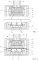
- Figures 1 to 7 show the steps of manufacturing the container in what is a single stage moulding operation.
- Figure 1 shows the flat sheet 4 of thermal formable material passing through the workstation with the mould 8 below the material and the pressure box 10 and the plug 6 located above the material.
- Figure 2 shows the first stage where the pressure box 10 is lowered onto the sheet 4 to clamp the sheet of material between the pressure box 12 and the frame part 8a of the mould.
- the plug 6 is urged downwardly by air pressure in the pressure box 10 into the mould 6 to a position in which the basic shape of the container is formed between the plug outer part 6a and the mould 8.
- Figure 3 discloses the plug inserted in the mould to form the basic shape of the container with a peripheral seal formed by the groove and rib seal 30, 32 to provide an airtight seal between the outer wall 26 of the container 2 and the base 28 so that the two parts can have different air pressures applied to them.
- air under pressure is applied to the exterior surface of the container outside the peripheral groove and rib seal 30, 32. to urge the material forming the wall 26 against the exterior surface of the mould 6a to define the precise shape of the container wall 26.
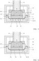
- FIG. 4 and 5 there is shown the formed container in which the peripheral seal formed by the groove and rib seal 30, 32 is formed to secure the container in position. Thereafter, air pressure in the pressure box 10 urges the insert 22 downwardly until it closes the gap, reference A.. In this position the main lower face of the insert 22 is aligned with the main base material of the container with the projections 24 projecting below the base of the container as shown in Figure 6 .
- the air pressure is applied to the underside of the material forming the container base 28 to push the material up around the projections 24 to form an annular recess in each of the projections and substantially simultaneously, vacuum is supplied to the interior of each projection to draw the material in the centre of each upwardly to form a cylindrical centrepiece thereby to provide in each projection an annular -shaped recess.
- Figure 4 air pressure applied to the underside of the base 28 of the container through supply channels 16a where it enters into the cylindrical part of the recess from where it is vented into the vacuum pipes 16
- Figure 6 illustrates the final step in the manufacture of the container in which the container is shown in its final form.
- Figure 7 shows the position where the container is released from the forming tool.
- the pressure box 10 carrying the plug 14 is raised and a short blast of pressurised air is applied to the underside of the container to assist in the release of the finished container from the mould 8.
- the walls of the recesses have a draught angle of typically 6o to assist in the separation of the container from the tool after the forming.
- Figure 7 also illustrates a cross-section of the finished container just before it is severed from the sheet material.
- Figure 8 shows in cross-section part of the base of the container in its final form
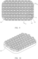
- Figure 9 shows a plan view of the base of one embodiment of the container containing an array of 7 rows of recesses providing a total number of 63 recesses distributed generally uniformly over the base of the container.
- Each recess has a hexagonal outer wall 36 and a cylindrical inner wall 38 defining therebetween an annular recess 40
- the recesses in each row have a spacing therebetween of 4.76 (approx.. 5.0 mm) and the width between the opposed interior faces of the walls of the hexagon shape 36 is approx.. 7.5 mm.
- the annular spacing between the inner face of the hexagon wall 36 and the cylindrical wall 38 which enables the capillary action typically comprises 0.98 mm (approx 1 mm).
- the size and shape of the recesses and the selected annular spacing may vary depending upon characteristics, such as its viscosity, of the liquid.
- Figure 8 comprises a side view of the container base illustrating the depth, (approximately 5 mm in this embodiment) of the recesses and hence the reservoir space below the main surface of the base of the container. The depth of the recesses may vary depending upon the nature and volume of the liquid emitted by the particular product for which the container is intended.
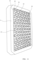
- FIG 10 shows a perspective view of part of the underside of the plug forming part of the the array of recesses illustrated in Figure 7, 8 and 9 .
- the thermo-formable material is forced by air pressure and/or by vacuum against the walls 36a and 38a of the tool to form respectively the outer walls 36 and inner walls 38 in the material.
- Figure 11 shows a view of the underside of the plug 6 showing the peripheral rib 32 which defines the clamping seal at the periphery of the base 28 of the container and the wall 26 of the container.
- the movable insert 22 contain the tool parts, namely the projections 24, which form the recesses 25.
- the plane of the base is elevated by 3° as shown in Figure 8 to assist in releasing the finished container from the mould 8.
- the surfaces between adjacent recesses 25 are formed with a run-off ramp to form an incline to enable water on the base of the container to drain into the adjacent recesses.
- surface of the base between adjacent recesses is provided with a central peak 44 which is 1 mm higher than the peripheral edge 42 of the recess to thus provide a run-off ramp to enable any liquid on the base of the container to drain into the adjacent recess to thereby minimise or eliminate pooling on the base
- the outer wall may be cylindrical or octagonal and the inner wall may alternatively be, for example, hexagonal or octagonal. It is also possible for one or both of the walls to be fluted.
- the pressure box 10 is closed to trap the sheet material 4 between the frame 8 and the lower edge 12 of the pressure box 10. Thereafter, as shown in Figure 5 , air pressure is fed to the space 34 between the pressure box and the plug 12, which urges the plug downwardly until the plug presses the material 4 down until it contacts the base of the mould as shown in Figure 4 . In this position, the sheet material is urged by the rib 32 into the groove 30 where it is clamped securely in position. In this way, the material defining the wall 26 of the container is clamped securely in position so that when further moulding takes place on the material at the base of the plug, the material defining the wall 26 of the container cannot flow into the base 28 of the container 2.
- a vacuum is applied through the vacuum pipe 16 to the interior of the plug 12 and the vacuum thus draws the material of the base of the container into the recesses 24 to form the capillary reservoirs 25 in the base of the container.
- containers in accordance with the present disclosure are formed entirely of the one single PET material which greatly facilitates recycling of the container after use.
- a further advantage is the elimination of the additional manufacturing steps currently used which rely on supplying a layer of absorbent material to absorb liquid released from the product, the layer being positioned in the base of the container and glued in position. As a result, there is a significant reduction in manufacturing cost of the containers.
- air pressure could be applied to the underside of the material to urge the material up into the grooves in the insert.
- the temperature of the air pressure may be adjusted to ensure that the base of the container remains sufficiently flexible to ensure that the material is drawn or pressed completely into the grooves.
- FIG. 7 the final stage of manufacturing the container is shown.
- the pressure box 10 is withdrawn, with the plug 14 and a quick blast of release air is applied to the underside of the mould through air supply openings 36 to release the container from the mould 6, from where it passes to a trimming station where the edge of the container walls are trimmed to a desired finished state.
- the temperature of the release air is low enough such that it does not affect or distort the shape of the moulded parts of the container.
- the embodiments described have a clamping surface extending around the periphery of the base adjacent the lower part of the container wall, it is envisaged that a further clamping surface could be provided extending between spaced positions on the peripheral clamping surface to divide the container volume into two parts, the base of one of the parts being provided with recesses having a capillary action as described previously. In this way, it would be possible to provide, for example, a ready meal having a meat or fish product in one part of the container having the recesses with the capillary function and vegetables in the other part.
- the base of the other part may be shaped to secure or locate a product such as a baked potato or similar vegetables to thereby prevent damage to such products during transit or storage.
- the base may have one or more predetermined regions defined by clamping lines, the regions having formed therein shapes adapted to the shape of a component to be packaged therein for transportation.
- the insert 22 would be formed with a number of insert sections each designed to act on the part of the insert surrounded by a clamping line.
- the array is shown as regularly arranged rows of recesses it is possible to have a non-uniform array of recesses to accommodate, for example, any differences in the leakage rates of different parts of the product being packaged in the container
Landscapes
- Engineering & Computer Science (AREA)
- Mechanical Engineering (AREA)
- Food Science & Technology (AREA)
- Blow-Moulding Or Thermoforming Of Plastics Or The Like (AREA)
- Packging For Living Organisms, Food Or Medicinal Products That Are Sensitive To Environmental Conditiond (AREA)
- Packages (AREA)
- Containers Having Bodies Formed In One Piece (AREA)
- Moulds For Moulding Plastics Or The Like (AREA)
- Casting Or Compression Moulding Of Plastics Or The Like (AREA)
Claims (12)
- Outil pour thermoformer un récipient (2) à partir d'un matériau thermoformable, le récipient (2) ayant une base (28) et une paroi ou des parois latérale(s) verticale(s), l'outil incluant un moule (8) ayant un profil mis en forme pour former la forme extérieure du récipient (2), et un bouchon (6) adapté à être inséré dans le moule (8) pour définir l'intérieur du récipient (2), le bouchon (6) ayant une face inférieure adaptée à définir le profil de la base (28) du récipient (2), dans lequel le profil de la face inférieure du bouchon (6) a au moins une ligne de serrage fermée (30, 32) ayant une surface de serrage, le moule (8) ayant une ligne de serrage conjuguée (30, 32) ayant une surface de serrage, les deux surfaces de serrage étant adaptées à serrer le matériau de la base (28) entre elles autour d'une zone prédéterminée de la base (28) pour définir et sécuriser le matériau de la zone prédéterminée de la base (28) séparément du reste du matériau du récipient (2), le profil de la face inférieure du bouchon (6) étant adapté à former une pluralité de saillies creuses (24) en dessous du plan de la base (28) pour former une série de retraits (25) dans ladite zone prédéterminée de la base (28) du récipient (2), caractérisé en ce que :
chaque retrait (25) comprend un retrait généralement annulaire (25) ayant une paroi externe (26) et une paroi coaxiale centrale (38), chaque retrait (25) étant adapté, dans un récipient (2), à recevoir et retenir par action capillaire du liquide dans le récipient (2), et afin d'empêcher à du liquide de former une flaque sur la surface de la base (28) du récipient (2) entre des retraits adjacents (25), le profil de la face inférieure du bouchon (6) est mis en forme de sorte que les surfaces de la base (28) entre des retraits adjacents (25) sont formées avec une rampe ou des rampes de ruissellement inclinée(s) pour permettre à du liquide sur la base (28) du récipient (2) de s'écouler dans les retraits adjacents (25). - Outil selon la revendication 1, dans lequel les saillies (24) sont positionnées et mises en forme pour former les retraits (25) dans chaque série avec un espacement entre eux d'approximativement 5,0 mm et une largeur entre les faces intérieures opposées des parois externes (36) des retraits (25) devant être d'approximativement 7,5 mm, et l'espacement annulaire entre la face de la paroi externe et la paroi interne (38) qui permet l'action capillaire est d'approximativement 1 mm, et dans lequel les saillies (24) sont dimensionnées pour former la profondeur de chaque retrait (25), et par conséquent la profondeur de l'espace de réservoir en dessous de la surface de la base (28) du récipient (2) devant être d'approximativement 5 mm.
- Outil selon la revendication 1 ou 2, dans lequel le bouchon (6) est mis en forme pour fournir autour de la périphérie de la base (28) une section de bord, dans laquelle section de bord le plan de la base (28) est élevé d'un angle de 3° pour aider à libérer un récipient fini (2) du moule (8).
- Outil selon l'une quelconque des revendications 1 à 3, dans lequel la surface de la base (28) entre des retraits adjacents (25) est pourvue d'un sommet généralement central 1 mm plus haut que le bord périphérique (42) des retraits adjacents (25) pour fournir ainsi une rampe ou des rampes de ruissellement inclinée(s) pour permettre à tout liquide sur la base (28) du récipient (2) de s'écouler dans les retraits adjacents (25).
- Outil selon la revendication 1, dans lequel la surface de serrage du bouchon (6) s'étend autour de la périphérie de la face inférieure du bouchon (6) adjacente à la paroi latérale du récipient (2), la surface de serrage du bouchon (6) étant adaptée à s'engager avec la surface de serrage du moule (8) pour serrer le matériau du récipient (2) entre elles pour définir et sécuriser le matériau de la base (28) du récipient (2) séparément du matériau de la paroi périphérique du récipient (2).
- Outil selon la revendication 1, dans lequel le bouchon (6) a une autre surface de serrage s'étendant en travers du récipient (2) d'une première position sur la surface de serrage périphérique à une 2nde position sur la surface de serrage périphérique espacée de la première position, l'autre surface de serrage étant adaptée à s'engager avec une autre surface de serrage du moule (8) pour serrer le matériau du récipient (2) entre elles pour définir une zone prédéterminée de la base (28) pour définir et sécuriser le matériau de la zone prédéterminée de la base séparément du matériau restant du récipient (2), lesdits retraits (25) étant formés uniquement dans ladite zone prédéterminée.
- Outil selon l'une quelconque des revendications 1 à 6, dans lequel la face inférieure du bouchon (6) a une rainure (30) ou nervure (32) périphérique s'étendant pour se situer autour de la périphérie de la base (28) adjacente à la paroi latérale du récipient (2), la rainure (30) ou nervure (32) se conjuguant à une nervure (32) ou rainure (30) périphérique correspondante verticale depuis la base du moule (8) pour former une surface de serrage pour serrer de manière sécurisée le matériau du récipient (2) entre le moule (8) et le bouchon (6).
- Outil selon l'une quelconque des revendications précédentes, dans lequel le profil de la face inférieure du bouchon (6) est formé sur un insert sécurisé au bouchon (6).
- Outil selon la revendication 8, dans lequel l'insert est sécurisé de manière amovible au bouchon (6) pour permettre à l'outil d'être facilement adapté à produire, sélectivement, une variété de récipients (2) ayant différents profils de base (28).
- Outil selon l'une quelconque des revendications 1 à 9, dans lequel le profil de la face inférieure du bouchon (6) a au moins deux lignes de serrage fermées ayant une surface de serrage, le moule (8) ayant deux lignes de serrage conjuguées correspondantes ayant une surface de serrage, les surfaces de serrage desdites deux lignes de serrage étant chacune adaptées à serrer le matériau de la base (28) entre elles autour d'une zone prédéterminée respective de la base (28) pour définir et sécuriser le matériau des zones prédéterminées de la base (28) séparément du reste du matériau du récipient (2).
- Procédé de fabrication d'un récipient (2) à partir d'une feuille de matériau thermoplastique incluant un moule (8) mis en forme pour définir le profil extérieur du récipient (2), placer une feuille de matériau thermoplastique sur le moule (8), chauffer la feuille de matériau thermoplastique à une température moulable, le récipient (2) ayant une base (28) et une paroi ou des parois latérale(s) verticale(s), fournir un bouchon (6) mis en forme pour fournir le profil interne du récipient (2) et étant adapté à être inséré dans le moule (8) pour serrer le matériau pour définir le récipient (2) entre eux, former une face inférieure du bouchon (6) pour définir le profil de la base (28) du récipient (2), appliquer un vide ou une pression atmosphérique au bouchon (6) pour tirer la feuille de matériau dans le profil du bouchon (6) en son sein pour former une série de retraits (25) dans la base (28) du récipient (2),le procédé étant caractérisé par le fait deformer chaque retrait (25) en tant que retrait généralement annulaire (25) ayant une paroi externe et une paroi coaxiale centrale, chaque retrait (25) étant adapté, en opération, à recevoir et retenir par action capillaire du liquide dans le récipient (2), et afin d'empêcher à du liquide de former une flaque sur la surface de la base (28) du récipient (2) entre des retraits adjacents (25), former les surfaces de la base (28) entre des retraits adjacents (25) avec une rampe ou des rampes de ruissellement pour permettre à du liquide sur la base (28) du récipient (2) de s'écouler dans les retraits adjacents (25).
- Procédé selon la revendication 11, incluant l'étape de formation dans la face inférieure du bouchon (6) d'une rainure (30) ou nervure (32) périphérique s'étendant autour de la périphérie du bouchon (6) adjacente à la paroi latérale du récipient (2), la rainure (30) ou nervure (32) se conjuguant à une nervure ou rainure périphérique correspondante verticale depuis ou formée dans la base du moule (8) pour serrer le matériau du récipient (2) de manière sécurisée entre le moule (8) et le bouchon (6) de sorte que la paroi du récipient (2) et la base (28) du récipient (2) peuvent ensuite être soumises à différentes pressions.
Priority Applications (2)
| Application Number | Priority Date | Filing Date | Title |
|---|---|---|---|
| SM20230432T SMT202300432T1 (it) | 2019-12-19 | 2020-12-18 | Metodo e strumento per la produzione di un contenitore da un materiale termoplastico |
| RS20230861A RS64753B1 (sr) | 2019-12-19 | 2020-12-18 | Postupak i alat za proizvodnju kontejnera od termoplastičnog materijala |
Applications Claiming Priority (1)
| Application Number | Priority Date | Filing Date | Title |
|---|---|---|---|
| GB1918861.4A GB2590476B (en) | 2019-12-19 | 2019-12-19 | A method and tool for manufacturing a container from a thermoplastic material |
Publications (2)
| Publication Number | Publication Date |
|---|---|
| EP3838552A1 EP3838552A1 (fr) | 2021-06-23 |
| EP3838552B1 true EP3838552B1 (fr) | 2023-06-28 |
Family
ID=69322956
Family Applications (1)
| Application Number | Title | Priority Date | Filing Date |
|---|---|---|---|
| EP20215582.6A Active EP3838552B1 (fr) | 2019-12-19 | 2020-12-18 | Procédé et outil de fabrication d'un récipient à partir d'un matériau thermoplastique |
Country Status (11)
| Country | Link |
|---|---|
| EP (1) | EP3838552B1 (fr) |
| DK (1) | DK3838552T3 (fr) |
| ES (1) | ES2961485T3 (fr) |
| FI (1) | FI3838552T3 (fr) |
| GB (3) | GB2590476B (fr) |
| HU (1) | HUE065357T2 (fr) |
| LT (1) | LT3838552T (fr) |
| PL (1) | PL3838552T3 (fr) |
| PT (1) | PT3838552T (fr) |
| RS (1) | RS64753B1 (fr) |
| SM (1) | SMT202300432T1 (fr) |
Family Cites Families (12)
| Publication number | Priority date | Publication date | Assignee | Title |
|---|---|---|---|---|
| GB1015669A (en) * | 1963-03-25 | 1966-01-05 | Waddington Ltd J | Improvements in or relating to trays, containers and the like |
| GB1091406A (en) * | 1964-10-30 | 1967-11-15 | Waddington Ltd J | Improvements in or relating to trays,containers and the like |
| JP2668847B2 (ja) * | 1993-08-30 | 1997-10-27 | 守 加茂 | 合成樹脂シート成型装置 |
| WO1995008480A1 (fr) * | 1993-09-24 | 1995-03-30 | Tetra Laval Holdings & Finance S.A. | Emballage pour produits alimentaires |
| PL183159B1 (pl) * | 1995-07-07 | 2002-05-31 | Convenience Food Sys Bv | Sposób wytwarzania opakowań |
| DE19601422A1 (de) * | 1996-01-17 | 1997-07-24 | Tetra Laval Holdings & Finance | Vorrichtung zum Tiefziehen eines thermoformbaren Kunststoffes |
| DE19700154A1 (de) * | 1997-01-06 | 1998-07-16 | Kraemer & Grebe Kg | Verpackungsmulde |
| EP1544129B1 (fr) * | 2003-10-15 | 2010-05-05 | Cryovac, Inc. | Récipient thermoformé en matière plastique et méthodes pour sa fabrication |
| FR2898107B1 (fr) * | 2006-03-06 | 2010-03-12 | Cgl Pack Service | Conteneur absorbant |
| CN103492166A (zh) * | 2011-02-24 | 2014-01-01 | 洪国善 | 细胞培养用支承体成型装置 |
| SG10201900252WA (en) * | 2019-01-11 | 2020-08-28 | Nat Univ Singapore | Three-dimensional printing of personalized pills |
| GB2580194B (en) * | 2019-06-18 | 2021-02-10 | Rem3Dy Health Ltd | 3D Printer |
-
2019
- 2019-12-19 GB GB1918861.4A patent/GB2590476B/en active Active
-
2020
- 2020-12-17 GB GB2202017.6A patent/GB2608664B/en active Active
- 2020-12-17 GB GB2020024.2A patent/GB2592720B/en active Active
- 2020-12-18 SM SM20230432T patent/SMT202300432T1/it unknown
- 2020-12-18 ES ES20215582T patent/ES2961485T3/es active Active
- 2020-12-18 EP EP20215582.6A patent/EP3838552B1/fr active Active
- 2020-12-18 FI FIEP20215582.6T patent/FI3838552T3/fi not_active Application Discontinuation
- 2020-12-18 PT PT202155826T patent/PT3838552T/pt unknown
- 2020-12-18 PL PL20215582.6T patent/PL3838552T3/pl unknown
- 2020-12-18 DK DK20215582.6T patent/DK3838552T3/da active
- 2020-12-18 HU HUE20215582A patent/HUE065357T2/hu unknown
- 2020-12-18 LT LTEP20215582.6T patent/LT3838552T/lt unknown
- 2020-12-18 RS RS20230861A patent/RS64753B1/sr unknown
Also Published As
| Publication number | Publication date |
|---|---|
| GB202202017D0 (en) | 2022-03-30 |
| PT3838552T (pt) | 2023-10-31 |
| LT3838552T (lt) | 2024-01-10 |
| EP3838552A1 (fr) | 2021-06-23 |
| GB2592720A (en) | 2021-09-08 |
| GB2608664A (en) | 2023-01-11 |
| GB2608664B (en) | 2024-08-07 |
| ES2961485T3 (es) | 2024-03-12 |
| FI3838552T3 (fi) | 2023-10-02 |
| SMT202300432T1 (it) | 2024-01-10 |
| GB2608664A9 (en) | 2023-02-01 |
| GB2590476A (en) | 2021-06-30 |
| PL3838552T3 (pl) | 2024-03-11 |
| GB201918861D0 (en) | 2020-02-05 |
| GB2592720B (en) | 2023-06-14 |
| HUE065357T2 (hu) | 2024-05-28 |
| RS64753B1 (sr) | 2023-11-30 |
| GB202020024D0 (en) | 2021-02-03 |
| GB2590476B (en) | 2023-02-01 |
| DK3838552T3 (da) | 2023-10-09 |
Similar Documents
| Publication | Publication Date | Title |
|---|---|---|
| EP1190958A2 (fr) | Récipient refermable | |
| US20100212827A1 (en) | Method Of Forming A Container Having An Internal Reservoir | |
| CA2432015C (fr) | Procede et appareil de fabrication d'un recipient en plastique etanche a la diffusion | |
| AU2002249196A1 (en) | Methods and apparatus for manufacturing a diffusion-tight plastic container | |
| EP3838552B1 (fr) | Procédé et outil de fabrication d'un récipient à partir d'un matériau thermoplastique | |
| US20080263942A1 (en) | Method and tooling for slitting a thermoformed container and container formed thereby | |
| EP3914434B1 (fr) | Procédé et outil de fabrication d'un récipient à partir d'un matériau thermoplastique et récipient | |
| US7033536B2 (en) | Method for thermoforming | |
| US11155022B2 (en) | Device, mould assembly and method for thermoforming of a product from a plastic film | |
| US4952264A (en) | Method for producing plastic components | |
| CN112976623B (zh) | 用于对包含柔软可变形内膜的层压件薄片进行边缘密封的方法、设备、和系统 | |
| GB2070504A (en) | Procedure for manufacturing a plastics container | |
| CN111231279A (zh) | 一种吸塑盒及用于生产该吸塑盒的吸塑模具 | |
| JP5849020B2 (ja) | 容器製造方法及び熱成形用成形型 | |
| GB2599178A (en) | A container formed from a thermo-plastic material | |
| JP2009057068A (ja) | 紙製トレーおよび紙製トレーの製造方法 | |
| JP6985591B2 (ja) | 樹脂製パネル及び製造方法 | |
| EP0786411A2 (fr) | Récipient composite | |
| GB2635549A (en) | Device and method for bonding a plastic inlay to a blank to form a tray and tray therewith | |
| KR20190090191A (ko) | 라벨이 부착되는 용기, 그의 제조장치 및 제조방법 | |
| JP2007223157A (ja) | 仕切付紙製容器の製造方法、仕切付紙製容器及び仕切付紙製容器の製造装置 | |
| CA2669319A1 (fr) | Procede de fabrication de conteneur avec reservoir interne |
Legal Events
| Date | Code | Title | Description |
|---|---|---|---|
| PUAI | Public reference made under article 153(3) epc to a published international application that has entered the european phase |
Free format text: ORIGINAL CODE: 0009012 |
|
| STAA | Information on the status of an ep patent application or granted ep patent |
Free format text: STATUS: THE APPLICATION HAS BEEN PUBLISHED |
|
| AK | Designated contracting states |
Kind code of ref document: A1 Designated state(s): AL AT BE BG CH CY CZ DE DK EE ES FI FR GB GR HR HU IE IS IT LI LT LU LV MC MK MT NL NO PL PT RO RS SE SI SK SM TR |
|
| STAA | Information on the status of an ep patent application or granted ep patent |
Free format text: STATUS: REQUEST FOR EXAMINATION WAS MADE |
|
| 17P | Request for examination filed |
Effective date: 20211216 |
|
| RBV | Designated contracting states (corrected) |
Designated state(s): AL AT BE BG CH CY CZ DE DK EE ES FI FR GB GR HR HU IE IS IT LI LT LU LV MC MK MT NL NO PL PT RO RS SE SI SK SM TR |
|
| RBV | Designated contracting states (corrected) |
Designated state(s): AL AT BE BG CH CY CZ DE DK EE ES FI FR GR HR HU IE IS IT LI LT LU LV MC MK MT NL NO PL PT RO RS SE SI SK SM TR |
|
| GRAP | Despatch of communication of intention to grant a patent |
Free format text: ORIGINAL CODE: EPIDOSNIGR1 |
|
| STAA | Information on the status of an ep patent application or granted ep patent |
Free format text: STATUS: GRANT OF PATENT IS INTENDED |
|
| RIC1 | Information provided on ipc code assigned before grant |
Ipc: B29C 51/04 20060101AFI20230207BHEP |
|
| INTG | Intention to grant announced |
Effective date: 20230303 |
|
| GRAS | Grant fee paid |
Free format text: ORIGINAL CODE: EPIDOSNIGR3 |
|
| GRAA | (expected) grant |
Free format text: ORIGINAL CODE: 0009210 |
|
| STAA | Information on the status of an ep patent application or granted ep patent |
Free format text: STATUS: THE PATENT HAS BEEN GRANTED |
|
| AK | Designated contracting states |
Kind code of ref document: B1 Designated state(s): AL AT BE BG CH CY CZ DE DK EE ES FI FR GR HR HU IE IS IT LI LT LU LV MC MK MT NL NO PL PT RO RS SE SI SK SM TR |
|
| REG | Reference to a national code |
Ref country code: CH Ref legal event code: EP |
|
| REG | Reference to a national code |
Ref country code: AT Ref legal event code: REF Ref document number: 1582324 Country of ref document: AT Kind code of ref document: T Effective date: 20230715 |
|
| REG | Reference to a national code |
Ref country code: IE Ref legal event code: FG4D |
|
| REG | Reference to a national code |
Ref country code: DE Ref legal event code: R096 Ref document number: 602020012984 Country of ref document: DE |
|
| REG | Reference to a national code |
Ref country code: FI Ref legal event code: FGE |
|
| REG | Reference to a national code |
Ref country code: DK Ref legal event code: T3 Effective date: 20231002 |
|
| REG | Reference to a national code |
Ref country code: NL Ref legal event code: FP |
|
| REG | Reference to a national code |
Ref country code: SE Ref legal event code: TRGR |
|
| REG | Reference to a national code |
Ref country code: PT Ref legal event code: SC4A Ref document number: 3838552 Country of ref document: PT Date of ref document: 20231031 Kind code of ref document: T Free format text: AVAILABILITY OF NATIONAL TRANSLATION Effective date: 20231024 |
|
| REG | Reference to a national code |
Ref country code: NO Ref legal event code: T2 Effective date: 20230628 |
|
| PG25 | Lapsed in a contracting state [announced via postgrant information from national office to epo] |
Ref country code: HR Free format text: LAPSE BECAUSE OF FAILURE TO SUBMIT A TRANSLATION OF THE DESCRIPTION OR TO PAY THE FEE WITHIN THE PRESCRIBED TIME-LIMIT Effective date: 20230628 |
|
| REG | Reference to a national code |
Ref country code: GR Ref legal event code: EP Ref document number: 20230401735 Country of ref document: GR Effective date: 20231113 |
|
| REG | Reference to a national code |
Ref country code: EE Ref legal event code: FG4A Ref document number: E023649 Country of ref document: EE Effective date: 20230928 |
|
| PG25 | Lapsed in a contracting state [announced via postgrant information from national office to epo] |
Ref country code: PL Free format text: LAPSE BECAUSE OF FAILURE TO SUBMIT A TRANSLATION OF THE DESCRIPTION OR TO PAY THE FEE WITHIN THE PRESCRIBED TIME-LIMIT Effective date: 20230628 |
|
| REG | Reference to a national code |
Ref country code: ES Ref legal event code: FG2A Ref document number: 2961485 Country of ref document: ES Kind code of ref document: T3 Effective date: 20240312 |
|
| REG | Reference to a national code |
Ref country code: SK Ref legal event code: T3 Ref document number: E 43295 Country of ref document: SK |
|
| REG | Reference to a national code |
Ref country code: DE Ref legal event code: R097 Ref document number: 602020012984 Country of ref document: DE |
|
| PLBE | No opposition filed within time limit |
Free format text: ORIGINAL CODE: 0009261 |
|
| STAA | Information on the status of an ep patent application or granted ep patent |
Free format text: STATUS: NO OPPOSITION FILED WITHIN TIME LIMIT |
|
| REG | Reference to a national code |
Ref country code: HU Ref legal event code: AG4A Ref document number: E065357 Country of ref document: HU |
|
| 26N | No opposition filed |
Effective date: 20240402 |
|
| PG25 | Lapsed in a contracting state [announced via postgrant information from national office to epo] |
Ref country code: SI Free format text: LAPSE BECAUSE OF FAILURE TO SUBMIT A TRANSLATION OF THE DESCRIPTION OR TO PAY THE FEE WITHIN THE PRESCRIBED TIME-LIMIT Effective date: 20230628 |
|
| REG | Reference to a national code |
Ref country code: CH Ref legal event code: PL |
|
| PG2D | Information on lapse in contracting state deleted |
Ref country code: PL |
|
| PG25 | Lapsed in a contracting state [announced via postgrant information from national office to epo] |
Ref country code: CH Free format text: LAPSE BECAUSE OF NON-PAYMENT OF DUE FEES Effective date: 20231231 |
|
| PG25 | Lapsed in a contracting state [announced via postgrant information from national office to epo] |
Ref country code: CH Free format text: LAPSE BECAUSE OF NON-PAYMENT OF DUE FEES Effective date: 20231231 |
|
| REG | Reference to a national code |
Ref country code: AT Ref legal event code: UEP Ref document number: 1582324 Country of ref document: AT Kind code of ref document: T Effective date: 20230628 |
|
| PGFP | Annual fee paid to national office [announced via postgrant information from national office to epo] |
Ref country code: IS Payment date: 20251124 Year of fee payment: 6 Ref country code: DE Payment date: 20251127 Year of fee payment: 6 |
|
| PGFP | Annual fee paid to national office [announced via postgrant information from national office to epo] |
Ref country code: LT Payment date: 20251126 Year of fee payment: 6 |
|
| PGFP | Annual fee paid to national office [announced via postgrant information from national office to epo] |
Ref country code: NO Payment date: 20251217 Year of fee payment: 6 Ref country code: MC Payment date: 20251215 Year of fee payment: 6 |
|
| PGFP | Annual fee paid to national office [announced via postgrant information from national office to epo] |
Ref country code: SM Payment date: 20251203 Year of fee payment: 6 Ref country code: AT Payment date: 20251119 Year of fee payment: 6 Ref country code: MK Payment date: 20251117 Year of fee payment: 6 Ref country code: PT Payment date: 20251211 Year of fee payment: 6 |
|
| PGFP | Annual fee paid to national office [announced via postgrant information from national office to epo] |
Ref country code: IT Payment date: 20251223 Year of fee payment: 6 Ref country code: FI Payment date: 20251216 Year of fee payment: 6 Ref country code: DK Payment date: 20251230 Year of fee payment: 6 |
|
| PGFP | Annual fee paid to national office [announced via postgrant information from national office to epo] |
Ref country code: LU Payment date: 20251219 Year of fee payment: 6 Ref country code: NL Payment date: 20251230 Year of fee payment: 6 Ref country code: FR Payment date: 20251230 Year of fee payment: 6 |
|
| PGFP | Annual fee paid to national office [announced via postgrant information from national office to epo] |
Ref country code: TR Payment date: 20251129 Year of fee payment: 6 Ref country code: GR Payment date: 20251127 Year of fee payment: 6 |
|
| PGFP | Annual fee paid to national office [announced via postgrant information from national office to epo] |
Ref country code: SE Payment date: 20251230 Year of fee payment: 6 |
|
| PGFP | Annual fee paid to national office [announced via postgrant information from national office to epo] |
Ref country code: IE Payment date: 20251230 Year of fee payment: 6 Ref country code: CZ Payment date: 20251118 Year of fee payment: 6 Ref country code: CY Payment date: 20251118 Year of fee payment: 6 |
|
| PGFP | Annual fee paid to national office [announced via postgrant information from national office to epo] |
Ref country code: LV Payment date: 20251125 Year of fee payment: 6 Ref country code: MT Payment date: 20251121 Year of fee payment: 6 |
|
| PGFP | Annual fee paid to national office [announced via postgrant information from national office to epo] |
Ref country code: PL Payment date: 20251118 Year of fee payment: 6 Ref country code: BG Payment date: 20251114 Year of fee payment: 6 |
|
| PGFP | Annual fee paid to national office [announced via postgrant information from national office to epo] |
Ref country code: EE Payment date: 20251118 Year of fee payment: 6 |
|
| PGFP | Annual fee paid to national office [announced via postgrant information from national office to epo] |
Ref country code: SK Payment date: 20251118 Year of fee payment: 6 Ref country code: RO Payment date: 20251222 Year of fee payment: 6 |
|
| PGFP | Annual fee paid to national office [announced via postgrant information from national office to epo] |
Ref country code: RS Payment date: 20251114 Year of fee payment: 6 |
|
| PGFP | Annual fee paid to national office [announced via postgrant information from national office to epo] |
Ref country code: ES Payment date: 20260202 Year of fee payment: 6 |
|
| PGFP | Annual fee paid to national office [announced via postgrant information from national office to epo] |
Ref country code: BE Payment date: 20251230 Year of fee payment: 6 |
|
| PGFP | Annual fee paid to national office [announced via postgrant information from national office to epo] |
Ref country code: HU Payment date: 20251121 Year of fee payment: 6 |