EP3838457B1 - Werkzeugeinheit zum erweiterungsbohren sehr präziser löcher - Google Patents
Werkzeugeinheit zum erweiterungsbohren sehr präziser löcher Download PDFInfo
- Publication number
- EP3838457B1 EP3838457B1 EP20211778.4A EP20211778A EP3838457B1 EP 3838457 B1 EP3838457 B1 EP 3838457B1 EP 20211778 A EP20211778 A EP 20211778A EP 3838457 B1 EP3838457 B1 EP 3838457B1
- Authority
- EP
- European Patent Office
- Prior art keywords
- clamping
- tool
- shank
- reaming
- tool unit
- Prior art date
- Legal status (The legal status is an assumption and is not a legal conclusion. Google has not performed a legal analysis and makes no representation as to the accuracy of the status listed.)
- Active
Links
Images
Classifications
-
- B—PERFORMING OPERATIONS; TRANSPORTING
- B23—MACHINE TOOLS; METAL-WORKING NOT OTHERWISE PROVIDED FOR
- B23B—TURNING; BORING
- B23B31/00—Chucks; Expansion mandrels; Adaptations thereof for remote control
- B23B31/02—Chucks
- B23B31/08—Chucks holding tools yieldably
-
- B—PERFORMING OPERATIONS; TRANSPORTING
- B23—MACHINE TOOLS; METAL-WORKING NOT OTHERWISE PROVIDED FOR
- B23B—TURNING; BORING
- B23B31/00—Chucks; Expansion mandrels; Adaptations thereof for remote control
- B23B31/005—Cylindrical shanks of tools
-
- B—PERFORMING OPERATIONS; TRANSPORTING
- B23—MACHINE TOOLS; METAL-WORKING NOT OTHERWISE PROVIDED FOR
- B23B—TURNING; BORING
- B23B31/00—Chucks; Expansion mandrels; Adaptations thereof for remote control
- B23B31/02—Chucks
- B23B31/10—Chucks characterised by the retaining or gripping devices or their immediate operating means
- B23B31/107—Retention by laterally-acting detents, e.g. pins, screws, wedges; Retention by loose elements, e.g. balls
-
- B—PERFORMING OPERATIONS; TRANSPORTING
- B23—MACHINE TOOLS; METAL-WORKING NOT OTHERWISE PROVIDED FOR
- B23D—PLANING; SLOTTING; SHEARING; BROACHING; SAWING; FILING; SCRAPING; LIKE OPERATIONS FOR WORKING METAL BY REMOVING MATERIAL, NOT OTHERWISE PROVIDED FOR
- B23D77/00—Reaming tools
- B23D77/006—Reaming tools with means for lubricating or cooling
-
- B—PERFORMING OPERATIONS; TRANSPORTING
- B23—MACHINE TOOLS; METAL-WORKING NOT OTHERWISE PROVIDED FOR
- B23B—TURNING; BORING
- B23B2231/00—Details of chucks, toolholder shanks or tool shanks
- B23B2231/02—Features of shanks of tools not relating to the operation performed by the tool
- B23B2231/026—Grooves
- B23B2231/0268—Radial grooves
-
- B—PERFORMING OPERATIONS; TRANSPORTING
- B23—MACHINE TOOLS; METAL-WORKING NOT OTHERWISE PROVIDED FOR
- B23B—TURNING; BORING
- B23B2231/00—Details of chucks, toolholder shanks or tool shanks
- B23B2231/24—Cooling or lubrication means
-
- B—PERFORMING OPERATIONS; TRANSPORTING
- B23—MACHINE TOOLS; METAL-WORKING NOT OTHERWISE PROVIDED FOR
- B23B—TURNING; BORING
- B23B2250/00—Compensating adverse effects during turning, boring or drilling
- B23B2250/12—Cooling and lubrication
Definitions
- the invention deals with a new design of a tool unit for CNC machines, containing a working tool and a clamping body, designed for reaming of very precise holes, especially from 3 to 32 mm in diameter and depths up to 120 mm from accuracy level IT5, which allows swinging floating movement of the working tool in radial degree of freedom, in the order of thousandths of mm.
- the tool units consist of a replaceable work tool and a clamping tool, which is a connecting member for connecting the work tool to the spindle of the machine tool.
- Weldon and Whistle-Notch clamping tools are the simplest and therefore most affordable clamping tools. They are used to clamping tools with a cylindrical shank provided with a corresponding side surface. Weldon clamping tools use for clamping one or two screws perpendicular to the tool axis, Whistle-Notch clamping tools use one or two screws inclined by 2°. In order to suppress the eccentricity due to the unilateral action of the clamping force, the inner diameter of the clamping tool is ground with accuracy level H4 and at the same time the use of tools with a precision shank h6 is required.
- Nonuniform weight distribution is due to the principle of clamping with a radial screw.
- the radial screw in turn, preferably keeps the tool in the correct position and prevents the tool from being pulled out of the clamping tool or slipped into it.
- Collet chucks belong to the group of clamping tools based on the mechanical principle of clamping of the tool.
- the principle of collet chucks consists in pushing the collet (replaceable insert) into the conical cavity of the chuck by means of a cap nut.
- the collet chuck is provided with notches around the circumference, which allow small elastic deformation and thus clamping of the tool.
- the clamping range of each insert is 0.5 to 1 mm.
- Hydraulic clamping tools work on principle of deformation of the thin inner wall of the clamping cavity by the pressure of hydraulic medium. Hydraulic clamping tools can be divided into two groups. They are divided according to the method of activation the clamping force.
- Thermal clamping sleeves are made of special materials and work on principle of thermal expansion of the material. Heating of the clamping sleeve allows the tool to be inserted and after cooling a very perfect and rigid clamping is achieved. To remove the tool, the chuck must be reheated. For heating it is necessary to use special devices usually operating on principle of induction heating and also fast air cooling is necessary. The heating of the clamping sleeve to a temperature of around 250°- 350° C is in the order of a few seconds. At this temperature, there are no structural changes in the material and it is important that it is not heated to a higher temperature. At temperatures around 500° C, tempering can occur and the housing material loses its mechanical properties and the thermal clamping tool can no longer perform its function.
- thermal clamping tools The biggest advantage of thermal clamping tools is the minimal dimensions of the clamping system, which allows the construction of very slim clamping tools for deep milling. High demands are again made on tool shanks - selected diameters and high accuracy. For clamping it is necessary to use special devices with hot-air or inductive heating and fast air cooling. Tools with a side face can also be clamped into thermal clamping tools, and when used correctly, the manufacturers declare that the thermal sleeves can manage more than 5,000 clamping cycles. The disadvantage is the need for additional equipment for clamping and unclamping the tool, and also from the point of view of work safety it is not ideal that there are components with high temperature in production process.
- JP H03 117533 A a shank of a reaming tool is placed into a chuck holder and the front surface of the shank is provided with a tube extension for entering of the coolant into the central cooling channel of the shank leading to the reamer.
- the outer front surface of the chucking holder is provided with a O-ring which is pressed against the chucking holder by a O-ring retainer which is pressed by a spring which is placed in a hollow in the main conical clamping body. This construction only secures effective flow of the coolant.
- the aim of the invention is to achieve a defined flexibility, rigidity and positional accuracy of the clamped reaming tool by means of a tool unit, which is designed especially for reaming of very precise holes in the diameter range of 3 - 32 mm at cutting speeds up to 250 m/min. on modern fully automated machining centers.
- the flexible element is formed by disc springs, helical spring or resilient mass.
- the outer diameter of the drive element corresponds to the inner diameter of the clamping nut screwed onto the clamping body.
- the working tool is made of structural steel, preferably with a tensile strength of 900-1000 MPa, with a soldered monolithic cutting part made of sintered carbide or cermet provided with an abrasion-resistant coating.
- the working tool is made of structural steel, including tooth grooves, in the cutting part of which cutting tips made of cubic boron nitride or diamond polycrystal are soldered.
- cylindrical shank of the working tool is made of structural steel, in the center of shank is a permanently pressed on sintered carbide cylinder, at the outer end of which a cutting part is created and continuous channels are provided on the surface of the cylinder for supply of cooling medium from the central channel to the cutting part.
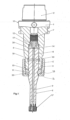
- Fig. 1 shows a tool unit according to the invention intended for reaming blind holes
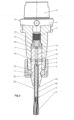
- Fig. 2 shows a tool unit according to the invention intended for reaming through holes
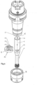
- Fig. 3 is a tool unit according to Figs. 1 and 2 in an exploded view.
- the tool unit 13 concerns tool clamping for machining high-precision holes in the accuracy level IT5 on high-precision CNC machines with tool rotation, at a cutting speed of up to 250 m/min.
- the tool unit 13 consists of a clamping body 1, at the upper end of which a conical part 2 is formed for mounting into a machine tool spindle (not shown).
- the clamping body 1 is provided with a cylindrical clamping cavity 4 and its face 15 is adapted for driving connection to a cylindrical shank 5 of a reaming tool 6 by means of a horseshoe-shaped drive element 11 with arms 27 which engage by the front projections 20 with the transverse groove 21.
- Fig. 3 wherein the transverse groove 21 is created on the face 15 of the clamping body 1.
- an inner recess 22 is provided on the drive element 11, by means of which the two arms 27 are formed and through which the drive element 11 is deposited in two opposite transverse grooves 23 formed on the cylindrical shank 5 of the reaming tool 6.
- the upper part 14 of the clamping cylindrical cavity 4 is adapted to freely accommodate the cylindrical clamping shank 5 of the reaming tool 6.
- a pre-loaded distance pin 12 is adapted for engagement with the front of the cylindrical shank 5 of the reaming tool 6, the distance pin 12 is secured by the cap nut 19 and is partialy pre-loaded with the flexible element 7, which are disc springs which define the axial play of the reaming tool 6.
- the working tool 6 is preferably made of structural steel, preferably with a tensile strength of 900-1000 MPa, with a soldered monolithic cutting part made of sintered carbide or cermet, provided with an abrasion-resistant coating.
- the drive element 11 is firmly pressed against the face 15 of the clamping body 1, whereby by means of tightening of the clamping nut 16, whose inner face 28 abuts the lower part of the drive element 11 and the arms 27 of which are inserted into the transverse grooves 23, the face 26 of the clamping shank 5 engages with the face of the distance pin 12, so by firm tightening of the clamping nut 16 the flexible element 7 is compressed by a force of 400-800 N. Further axial compression of the flexible element 7, in this embodiment made as disc springs, takes place by means of the clamping nut 16, which rests frontally against the drive element 11 extending into transverse grooves 23 formed on the cylindrical shank 5 of the working tool 6.
- a main channel 8 for guiding the cooling medium at a pressure of 40-100 bar is formed in the axis of the clamping shank 5 of the reaming tool 6, from which the pressurized cooling medium is distributed to the central channel 9, which mouths in the cutting part 17 of the tool 6 and the pressurized cooling medium is further distributed from the main channel 8 to the transverse channels 10, which mouth into the annular cavity 18 and further into the cylindrical cavity 4, whereby due to the action of the uniform overpressure of the cooling medium in the cylindrical cavity 4 of the clamping body 1, the axis of the clamping cylindrical shank 5 of the working tool 6 will be set without play into the ideal axis with the axis of the cylindrical clamping cavity 4.
- the drive element 11 has an outer diameter corresponding to the inner diameter of the clamping nut 16.
- Fig. 2 shows an embodiment where the cylindrical shank 5 of the working tool 6 is made of structural steel, in the center of clamping shank 5 there is a permanently pressed on sintered carbide cylinder 25, at the outer end of which a cutting part 17 is created and continuous channels 24 are provided on the cylinder surface for supply of cooling medium from the central channel 9 to the cutting part 17.
- the present invention is characterized in that the tool unit consists of a clamping body with a very precise concentric cylindrical hole, in which the cylindrical clamping part of the working tool with a radial play of 5-10 ⁇ m is arranged.
- the working tool is rotatably connected to the clamping body by means of a drive element which rotatably connects the body to the clamping part of the reamer and axially secures its position with a defined force axial spring loading.
- the design of the tool unit allows the swinging (floating) movement of the clamping part of the working tool in radial degree of freedom in the order of thousandths of millimeter during reaming, thus setting the cutting part of the reaming tool into the so-called ideal reaming axis, i.e. when all cutting edges remove the same chip.
- the overpressure of the cooling medium is used for this purpose, and the process fluid inlet pressure of the cooling medium must be at least 40 bar.
Landscapes
- Engineering & Computer Science (AREA)
- Mechanical Engineering (AREA)
- Gripping On Spindles (AREA)
Claims (6)
- Werkzeugeinheit zum Erweiterungsbohren sehr präzizer Löchern mit einem Spannkörper, der mit einem zylindrischen Spannhohlraum zur Befestigung eines Werkzeugschaftes versehen ist, wobei der Schaft von einem Hauptkanal für Kühlmittel durchsetzt ist, dadurch gekennzeichnet, dass am Spannschaft (5) des Werkzeuges (6) zwei gegenüberliegende Quernuten (23) angebracht sind, in die die Arme (27) des hufeisenförmigen Halteelements (11), das durch die innere zentrale Aussparung (22) gebildet wird, mit ihren Seitenflächen eingeführt werden, während eine Quernut (21) in der unteren Fläche (15) des Klemmkörpers (1) ausgebildet ist, in die die an der Oberseite des Halteelements (11) ausgebildeten stirnseitigen Vorsprünge (20) eingreifen, wobei eine auf den Klemmkörper (1) aufgeschraubte Spannmutter (16) bis zur Unterseite des Halteelements (11) reicht, wobei am oberen Ende (14) des klemmzylindrischen Hohlraums (4) ein federbelasteter, durch eine Überlaufmutter (19) gesicherter Aufnahmezapfen (12) angeordnet ist, über dem ein das axiale Spiel des Reibwerkzeugs (6) definierendes flexibles Element (7) angeordnet ist, das von oben auf einem Sitz im Hohlraum des Klemmkörpers (1) aufliegt (26), wobei ein Hauptkanal (8) zur Führung des Kühlmediums für einen Druck von 40-100 bar angeordnet ist, von dem aus das Kühlmedium zu einem stromabwärts gelegenen Zentralkanal (9), der im Schneidteil (17) des Werkzeugs (6) mündet, und weiter zu einem Querkanal (10), der im Zwischenhohlraum (18) zwischen dem Schaft (5) und dem Hohlraum (4) des Spannkörpers (1) mündet, und von dort zum zylindrischen Hohlraum (4) verteilt wird.
- Werkzeugeinheit nach Anspruch 1, dadurch gekennzeichnet, dass das federnde Element (7) eine Tellerfeder, eine Schraubenfeder oder eine federnde Masse umfasst.
- Werkzeugeinheit nach Anspruch 1, dadurch gekennzeichnet, dass der Außendurchmesser des Spannelementes (11) dem Innendurchmesser der auf den Spannkörper (1) geschraubten Spannmutter (16) entspricht.
- Werkzeugeinheit nach Anspruch 1, dadurch gekennzeichnet, dass das Arbeitswerkzeug (6) aus Baustahl, vorzugsweise mit einer Festigkeit von 900-1000 MPa, mit einem monolithischen Schneidteil aus gesintertem Hartmetall oder Cermet hergestellt und mit einer abriebfesten Beschichtung versehen ist.
- Werkzeugeinheit nach Anspruch 1, dadurch gekennzeichnet, dass das Arbeitswerkzeug (6) aus Baustahl mit Zahnnuten gebildet ist, in die Schneidabschnitte (17) aus kubischem Bornitrid oder polykristallinem Diamant eingelötet sind.
- Werkzeugeinheit nach Anspruch 1, dadurch gekennzeichnet, dass der zylindrische Schaft (5) des Arbeitswerkzeugs (6) aus Baustahl gebildet ist, in dessen Zentrum eine Rolle (25) aus gesintertem Hartmetall untrennbar eingepresst ist, an deren äußerem Ende ein Schneidteil (17) ausgebildet ist und auf der Oberfläche der Rolle (25) durchgehende Kanäle (24) zur Zuführung von Kühlmedium vom zentralen Kanal (8) zum Schneidteil (17) ausgebildet sind.
Applications Claiming Priority (1)
| Application Number | Priority Date | Filing Date | Title |
|---|---|---|---|
| CZ2019773A CZ308639B6 (cs) | 2019-12-13 | 2019-12-13 | Nástrojová jednotka pro vystružování velmi přesných děr |
Related Parent Applications (1)
| Application Number | Title | Priority Date | Filing Date |
|---|---|---|---|
| CZ2019773 Previously-Filed-Application | 2019-12-13 |
Publications (3)
| Publication Number | Publication Date |
|---|---|
| EP3838457A1 EP3838457A1 (de) | 2021-06-23 |
| EP3838457C0 EP3838457C0 (de) | 2024-07-31 |
| EP3838457B1 true EP3838457B1 (de) | 2024-07-31 |
Family
ID=74165825
Family Applications (1)
| Application Number | Title | Priority Date | Filing Date |
|---|---|---|---|
| EP20211778.4A Active EP3838457B1 (de) | 2019-12-13 | 2020-12-04 | Werkzeugeinheit zum erweiterungsbohren sehr präziser löcher |
Country Status (2)
| Country | Link |
|---|---|
| EP (1) | EP3838457B1 (de) |
| CZ (1) | CZ308639B6 (de) |
Families Citing this family (3)
| Publication number | Priority date | Publication date | Assignee | Title |
|---|---|---|---|---|
| CN113319606B (zh) * | 2021-08-02 | 2021-11-02 | 江苏刘一刀精密机械有限公司 | 一种具有防退卡簧的刀具锁紧结构 |
| CN118342015B (zh) * | 2024-06-11 | 2024-10-01 | 爱博特新能源科技江苏有限公司 | 一种led灯具外壳加工机床 |
| CN118578157B (zh) * | 2024-08-06 | 2025-01-17 | 杭州鄂达精密机电科技有限公司 | 一种用于阀部件加工的内冷型数控刀座 |
Family Cites Families (7)
| Publication number | Priority date | Publication date | Assignee | Title |
|---|---|---|---|---|
| US2813723A (en) * | 1954-10-27 | 1957-11-19 | Marcellus Mfg Co | Floating reamer holder |
| US3999769A (en) * | 1975-02-24 | 1976-12-28 | Bayer Jack L | Tool holder for machine tools |
| JPH03117533A (ja) * | 1989-09-29 | 1991-05-20 | Mazda Motor Corp | フローティングツールのクーラント供給装置 |
| DE10326928B4 (de) * | 2003-06-16 | 2009-07-02 | MAPAL Fabrik für Präzisionswerkzeuge Dr. Kress KG | Schnittstelle zwischen zwei Teilelementen eines Werkzeugsystems |
| DE102013203297B3 (de) * | 2013-02-27 | 2014-05-28 | Kennametal Inc. | Werkzeughalter zum passiven Ausgleich eines radialen Versatzes zwischen einer Bohrlochachse und einer Werkzeugachse |
| US10231741B2 (en) * | 2015-07-01 | 2019-03-19 | Viant As&O Holdings, Llc | Reamer handle coupling |
| DE102018206891A1 (de) * | 2018-05-04 | 2019-11-07 | Gühring KG | Werkzeugaufnahme für ein Zerspanungswerkzeug mit Tiefenanschlag und Zerspanungsvorrichtung |
-
2019
- 2019-12-13 CZ CZ2019773A patent/CZ308639B6/cs unknown
-
2020
- 2020-12-04 EP EP20211778.4A patent/EP3838457B1/de active Active
Also Published As
| Publication number | Publication date |
|---|---|
| EP3838457A1 (de) | 2021-06-23 |
| EP3838457C0 (de) | 2024-07-31 |
| CZ2019773A3 (cs) | 2021-01-20 |
| CZ308639B6 (cs) | 2021-01-20 |
Similar Documents
| Publication | Publication Date | Title |
|---|---|---|
| EP3838457B1 (de) | Werkzeugeinheit zum erweiterungsbohren sehr präziser löcher | |
| KR100298065B1 (ko) | 공구홀더및이러한공구홀더내에절삭공구를장착하기위한방법 | |
| US5516243A (en) | Reamer chuck and tool expander | |
| US5277435A (en) | Standard shank and method for directly locating rotating cutting tools in a machine tool work spindle | |
| JP5139789B2 (ja) | ワークピースをチャック上に正確に位置決めするワークピースキャリア並びにチャック及びワークピースキャリアを有するクランプ装置 | |
| KR20010093805A (ko) | 중심에 형상오차를 갖는 공작물의 연마방법과 장치 | |
| KR20200047531A (ko) | 콜렛 홀더와 툴 어댑터 사이의 인터페이스 | |
| JPH06270002A (ja) | クランプ接続装置 | |
| WO1994026448A1 (en) | Tool extender for machining applications | |
| CN111957989A (zh) | 一种深孔槽的加工方法 | |
| EP4237183A1 (de) | Spannsystem für reibbohrwerkzeuge | |
| CN100540193C (zh) | 用于铣刀架的心轴 | |
| SE460712B (sv) | Revolverhuvud foer en svarv och haertill avpassad verktygshaallare | |
| CZ33886U1 (cs) | Nástrojová jednotka pro vystružování velmi přesných děr | |
| EP0418041A2 (de) | Werkzeug, insbesondere zur Feinbearbeitung in spanabhebender Fertigung | |
| US10189090B2 (en) | Drilling tool | |
| US3301102A (en) | Tool guide-locator | |
| US10940541B2 (en) | Shrink fit adapter for a collet chuck | |
| CZ11022U1 (cs) | Nástrojová jednotka zejména pro čelní frézování velmi přesných děr | |
| US20250114888A1 (en) | Clamping component and tool holder | |
| AU2023340836B2 (en) | A single unit tool holder device for easy clamping and de-clamping of a tool shank | |
| CN221232002U (zh) | 跟刀架及长轴加工设备 | |
| EP0201298A2 (de) | Automatischer richtender ersetzbarer Werkstückträger | |
| US2867440A (en) | Floating reamer or tap holder | |
| CZ11702U1 (cs) | Nástrojová jednotka zejména pro frézování velmi přesných děr a ploch |
Legal Events
| Date | Code | Title | Description |
|---|---|---|---|
| PUAI | Public reference made under article 153(3) epc to a published international application that has entered the european phase |
Free format text: ORIGINAL CODE: 0009012 |
|
| STAA | Information on the status of an ep patent application or granted ep patent |
Free format text: STATUS: THE APPLICATION HAS BEEN PUBLISHED |
|
| AK | Designated contracting states |
Kind code of ref document: A1 Designated state(s): AL AT BE BG CH CY CZ DE DK EE ES FI FR GB GR HR HU IE IS IT LI LT LU LV MC MK MT NL NO PL PT RO RS SE SI SK SM TR |
|
| STAA | Information on the status of an ep patent application or granted ep patent |
Free format text: STATUS: REQUEST FOR EXAMINATION WAS MADE |
|
| 17P | Request for examination filed |
Effective date: 20211215 |
|
| RBV | Designated contracting states (corrected) |
Designated state(s): AL AT BE BG CH CY CZ DE DK EE ES FI FR GB GR HR HU IE IS IT LI LT LU LV MC MK MT NL NO PL PT RO RS SE SI SK SM TR |
|
| GRAP | Despatch of communication of intention to grant a patent |
Free format text: ORIGINAL CODE: EPIDOSNIGR1 |
|
| STAA | Information on the status of an ep patent application or granted ep patent |
Free format text: STATUS: GRANT OF PATENT IS INTENDED |
|
| INTG | Intention to grant announced |
Effective date: 20240304 |
|
| RAP3 | Party data changed (applicant data changed or rights of an application transferred) |
Owner name: FINAL TOOLS A.S. |
|
| GRAS | Grant fee paid |
Free format text: ORIGINAL CODE: EPIDOSNIGR3 |
|
| GRAA | (expected) grant |
Free format text: ORIGINAL CODE: 0009210 |
|
| STAA | Information on the status of an ep patent application or granted ep patent |
Free format text: STATUS: THE PATENT HAS BEEN GRANTED |
|
| AK | Designated contracting states |
Kind code of ref document: B1 Designated state(s): AL AT BE BG CH CY CZ DE DK EE ES FI FR GB GR HR HU IE IS IT LI LT LU LV MC MK MT NL NO PL PT RO RS SE SI SK SM TR |
|
| REG | Reference to a national code |
Ref country code: CH Ref legal event code: EP Ref country code: GB Ref legal event code: FG4D |
|
| REG | Reference to a national code |
Ref country code: DE Ref legal event code: R096 Ref document number: 602020034791 Country of ref document: DE |
|
| REG | Reference to a national code |
Ref country code: IE Ref legal event code: FG4D |
|
| U01 | Request for unitary effect filed |
Effective date: 20240821 |
|
| U07 | Unitary effect registered |
Designated state(s): AT BE BG DE DK EE FI FR IT LT LU LV MT NL PT RO SE SI Effective date: 20240902 |
|
| U20 | Renewal fee for the european patent with unitary effect paid |
Year of fee payment: 5 Effective date: 20241106 |
|
| PG25 | Lapsed in a contracting state [announced via postgrant information from national office to epo] |
Ref country code: NO Free format text: LAPSE BECAUSE OF FAILURE TO SUBMIT A TRANSLATION OF THE DESCRIPTION OR TO PAY THE FEE WITHIN THE PRESCRIBED TIME-LIMIT Effective date: 20241031 |
|
| PG25 | Lapsed in a contracting state [announced via postgrant information from national office to epo] |
Ref country code: GR Free format text: LAPSE BECAUSE OF FAILURE TO SUBMIT A TRANSLATION OF THE DESCRIPTION OR TO PAY THE FEE WITHIN THE PRESCRIBED TIME-LIMIT Effective date: 20241101 Ref country code: PL Free format text: LAPSE BECAUSE OF FAILURE TO SUBMIT A TRANSLATION OF THE DESCRIPTION OR TO PAY THE FEE WITHIN THE PRESCRIBED TIME-LIMIT Effective date: 20240731 |
|
| PG25 | Lapsed in a contracting state [announced via postgrant information from national office to epo] |
Ref country code: IS Free format text: LAPSE BECAUSE OF FAILURE TO SUBMIT A TRANSLATION OF THE DESCRIPTION OR TO PAY THE FEE WITHIN THE PRESCRIBED TIME-LIMIT Effective date: 20241130 |
|
| PG25 | Lapsed in a contracting state [announced via postgrant information from national office to epo] |
Ref country code: HR Free format text: LAPSE BECAUSE OF FAILURE TO SUBMIT A TRANSLATION OF THE DESCRIPTION OR TO PAY THE FEE WITHIN THE PRESCRIBED TIME-LIMIT Effective date: 20240731 |
|
| PG25 | Lapsed in a contracting state [announced via postgrant information from national office to epo] |
Ref country code: ES Free format text: LAPSE BECAUSE OF FAILURE TO SUBMIT A TRANSLATION OF THE DESCRIPTION OR TO PAY THE FEE WITHIN THE PRESCRIBED TIME-LIMIT Effective date: 20240731 Ref country code: RS Free format text: LAPSE BECAUSE OF FAILURE TO SUBMIT A TRANSLATION OF THE DESCRIPTION OR TO PAY THE FEE WITHIN THE PRESCRIBED TIME-LIMIT Effective date: 20241031 |
|
| PG25 | Lapsed in a contracting state [announced via postgrant information from national office to epo] |
Ref country code: RS Free format text: LAPSE BECAUSE OF FAILURE TO SUBMIT A TRANSLATION OF THE DESCRIPTION OR TO PAY THE FEE WITHIN THE PRESCRIBED TIME-LIMIT Effective date: 20241031 Ref country code: PL Free format text: LAPSE BECAUSE OF FAILURE TO SUBMIT A TRANSLATION OF THE DESCRIPTION OR TO PAY THE FEE WITHIN THE PRESCRIBED TIME-LIMIT Effective date: 20240731 Ref country code: NO Free format text: LAPSE BECAUSE OF FAILURE TO SUBMIT A TRANSLATION OF THE DESCRIPTION OR TO PAY THE FEE WITHIN THE PRESCRIBED TIME-LIMIT Effective date: 20241031 Ref country code: IS Free format text: LAPSE BECAUSE OF FAILURE TO SUBMIT A TRANSLATION OF THE DESCRIPTION OR TO PAY THE FEE WITHIN THE PRESCRIBED TIME-LIMIT Effective date: 20241130 Ref country code: HR Free format text: LAPSE BECAUSE OF FAILURE TO SUBMIT A TRANSLATION OF THE DESCRIPTION OR TO PAY THE FEE WITHIN THE PRESCRIBED TIME-LIMIT Effective date: 20240731 Ref country code: GR Free format text: LAPSE BECAUSE OF FAILURE TO SUBMIT A TRANSLATION OF THE DESCRIPTION OR TO PAY THE FEE WITHIN THE PRESCRIBED TIME-LIMIT Effective date: 20241101 Ref country code: ES Free format text: LAPSE BECAUSE OF FAILURE TO SUBMIT A TRANSLATION OF THE DESCRIPTION OR TO PAY THE FEE WITHIN THE PRESCRIBED TIME-LIMIT Effective date: 20240731 |
|
| PG25 | Lapsed in a contracting state [announced via postgrant information from national office to epo] |
Ref country code: SM Free format text: LAPSE BECAUSE OF FAILURE TO SUBMIT A TRANSLATION OF THE DESCRIPTION OR TO PAY THE FEE WITHIN THE PRESCRIBED TIME-LIMIT Effective date: 20240731 |
|
| PG25 | Lapsed in a contracting state [announced via postgrant information from national office to epo] |
Ref country code: CZ Free format text: LAPSE BECAUSE OF FAILURE TO SUBMIT A TRANSLATION OF THE DESCRIPTION OR TO PAY THE FEE WITHIN THE PRESCRIBED TIME-LIMIT Effective date: 20240731 |
|
| PG25 | Lapsed in a contracting state [announced via postgrant information from national office to epo] |
Ref country code: SK Free format text: LAPSE BECAUSE OF FAILURE TO SUBMIT A TRANSLATION OF THE DESCRIPTION OR TO PAY THE FEE WITHIN THE PRESCRIBED TIME-LIMIT Effective date: 20240731 |
|
| PLBE | No opposition filed within time limit |
Free format text: ORIGINAL CODE: 0009261 |
|
| STAA | Information on the status of an ep patent application or granted ep patent |
Free format text: STATUS: NO OPPOSITION FILED WITHIN TIME LIMIT |
|
| PG25 | Lapsed in a contracting state [announced via postgrant information from national office to epo] |
Ref country code: MC Free format text: LAPSE BECAUSE OF FAILURE TO SUBMIT A TRANSLATION OF THE DESCRIPTION OR TO PAY THE FEE WITHIN THE PRESCRIBED TIME-LIMIT Effective date: 20240731 |
|
| 26N | No opposition filed |
Effective date: 20250501 |
|
| REG | Reference to a national code |
Ref country code: CH Ref legal event code: PL |
|
| GBPC | Gb: european patent ceased through non-payment of renewal fee |
Effective date: 20241204 |
|
| PG25 | Lapsed in a contracting state [announced via postgrant information from national office to epo] |
Ref country code: GB Free format text: LAPSE BECAUSE OF NON-PAYMENT OF DUE FEES Effective date: 20241204 |
|
| PG25 | Lapsed in a contracting state [announced via postgrant information from national office to epo] |
Ref country code: CH Free format text: LAPSE BECAUSE OF NON-PAYMENT OF DUE FEES Effective date: 20241231 |
|
| PG25 | Lapsed in a contracting state [announced via postgrant information from national office to epo] |
Ref country code: IE Free format text: LAPSE BECAUSE OF NON-PAYMENT OF DUE FEES Effective date: 20241204 |