EP3837580B1 - Verfahren zum abtasten eines optischen strahls unter verwendung eines akustooptischen ablenkers mit ansteuerung durch gechirpte akustische signale - Google Patents
Verfahren zum abtasten eines optischen strahls unter verwendung eines akustooptischen ablenkers mit ansteuerung durch gechirpte akustische signale Download PDFInfo
- Publication number
- EP3837580B1 EP3837580B1 EP19794627.0A EP19794627A EP3837580B1 EP 3837580 B1 EP3837580 B1 EP 3837580B1 EP 19794627 A EP19794627 A EP 19794627A EP 3837580 B1 EP3837580 B1 EP 3837580B1
- Authority
- EP
- European Patent Office
- Prior art keywords
- acousto
- acoustic
- acoustic wave
- crystal layer
- optic
- Prior art date
- Legal status (The legal status is an assumption and is not a legal conclusion. Google has not performed a legal analysis and makes no representation as to the accuracy of the status listed.)
- Active
Links
Images




Classifications
-
- G—PHYSICS
- G02—OPTICS
- G02F—OPTICAL DEVICES OR ARRANGEMENTS FOR THE CONTROL OF LIGHT BY MODIFICATION OF THE OPTICAL PROPERTIES OF THE MEDIA OF THE ELEMENTS INVOLVED THEREIN; NON-LINEAR OPTICS; FREQUENCY-CHANGING OF LIGHT; OPTICAL LOGIC ELEMENTS; OPTICAL ANALOGUE/DIGITAL CONVERTERS
- G02F1/00—Devices or arrangements for the control of the intensity, colour, phase, polarisation or direction of light arriving from an independent light source, e.g. switching, gating or modulating; Non-linear optics
- G02F1/01—Devices or arrangements for the control of the intensity, colour, phase, polarisation or direction of light arriving from an independent light source, e.g. switching, gating or modulating; Non-linear optics for the control of the intensity, phase, polarisation or colour
- G02F1/11—Devices or arrangements for the control of the intensity, colour, phase, polarisation or direction of light arriving from an independent light source, e.g. switching, gating or modulating; Non-linear optics for the control of the intensity, phase, polarisation or colour based on acousto-optical elements, e.g. using variable diffraction by sound or like mechanical waves
- G02F1/113—Circuit or control arrangements
-
- G—PHYSICS
- G01—MEASURING; TESTING
- G01N—INVESTIGATING OR ANALYSING MATERIALS BY DETERMINING THEIR CHEMICAL OR PHYSICAL PROPERTIES
- G01N21/00—Investigating or analysing materials by the use of optical means, i.e. using sub-millimetre waves, infrared, visible or ultraviolet light
- G01N21/62—Systems in which the material investigated is excited whereby it emits light or causes a change in wavelength of the incident light
- G01N21/63—Systems in which the material investigated is excited whereby it emits light or causes a change in wavelength of the incident light optically excited
- G01N21/64—Fluorescence; Phosphorescence
- G01N21/645—Specially adapted constructive features of fluorimeters
-
- G—PHYSICS
- G02—OPTICS
- G02B—OPTICAL ELEMENTS, SYSTEMS OR APPARATUS
- G02B21/00—Microscopes
- G02B21/0004—Microscopes specially adapted for specific applications
- G02B21/002—Scanning microscopes
- G02B21/0024—Confocal scanning microscopes (CSOMs) or confocal "macroscopes"; Accessories which are not restricted to use with CSOMs, e.g. sample holders
- G02B21/0036—Scanning details, e.g. scanning stages
-
- G—PHYSICS
- G02—OPTICS
- G02F—OPTICAL DEVICES OR ARRANGEMENTS FOR THE CONTROL OF LIGHT BY MODIFICATION OF THE OPTICAL PROPERTIES OF THE MEDIA OF THE ELEMENTS INVOLVED THEREIN; NON-LINEAR OPTICS; FREQUENCY-CHANGING OF LIGHT; OPTICAL LOGIC ELEMENTS; OPTICAL ANALOGUE/DIGITAL CONVERTERS
- G02F1/00—Devices or arrangements for the control of the intensity, colour, phase, polarisation or direction of light arriving from an independent light source, e.g. switching, gating or modulating; Non-linear optics
- G02F1/29—Devices or arrangements for the control of the intensity, colour, phase, polarisation or direction of light arriving from an independent light source, e.g. switching, gating or modulating; Non-linear optics for the control of the position or the direction of light beams, i.e. deflection
- G02F1/33—Acousto-optical deflection devices
-
- G—PHYSICS
- G01—MEASURING; TESTING
- G01N—INVESTIGATING OR ANALYSING MATERIALS BY DETERMINING THEIR CHEMICAL OR PHYSICAL PROPERTIES
- G01N21/00—Investigating or analysing materials by the use of optical means, i.e. using sub-millimetre waves, infrared, visible or ultraviolet light
- G01N21/62—Systems in which the material investigated is excited whereby it emits light or causes a change in wavelength of the incident light
- G01N21/63—Systems in which the material investigated is excited whereby it emits light or causes a change in wavelength of the incident light optically excited
- G01N21/64—Fluorescence; Phosphorescence
- G01N21/645—Specially adapted constructive features of fluorimeters
- G01N2021/6463—Optics
-
- G—PHYSICS
- G01—MEASURING; TESTING
- G01N—INVESTIGATING OR ANALYSING MATERIALS BY DETERMINING THEIR CHEMICAL OR PHYSICAL PROPERTIES
- G01N2201/00—Features of devices classified in G01N21/00
- G01N2201/10—Scanning
- G01N2201/106—Acousto-optical scan
Definitions
- the object of the invention relates to a method for scanning with an optical beam using a first acousto-optic deflector having an optical axis along a Z-axis and at least one acousto-optic crystal layer.
- Scanning methods particularly 3-dimensional laser scanning methods play an important role in the study of biological samples, during which the structure of the biological sample, the distribution of fluorescent markers, and the surface receptors of cells, etc. are mapped out.
- the known scanning methods usually use 3-dimensional laser scanning microscopes, which may be confocal or two photon microscopes.
- confocal microscope technology a pinhole is placed in front of the detector to filter out light arriving from planes other than the plane of focus of the microscope objective. In this way it is possible to create images of planes in the sample (e.g. biological sample) lying at various depths.
- Two photon laser scanning microscopes operate with lower photon energy but greater intensity laser light, from which the simultaneous absorption of two photons is necessary to excite the fluorophore. Subsequently, the emitted fluorescence photon may be detected with a detector.
- 3-dimensional scanning may also be implemented by moving the microscope stage with a stepper motor, for example, although this method is rarely used in practice due to its slowness and mechanical complexity. Therefore, during the examination of biological samples, instead of moving the sample, the focal point of the laser beam is moved is such a way that the laser beam is deflected in the X-Y plane, and the depth of the focal plane is controlled by moving the objective along the Z-axis.
- a 3-dimensional scanning system that uses the above principle is disclosed in patent number US 8,559,085 , in the case of which the position of the focal point is moved using four acousto-optic deflectors arranged one after the other.
- the movement of the focal point in the X-Y plane is performed by regulating the frequency difference of the acoustic waves generated in the deflectors, while the position of the focal point in the Z-axis direction is changed with the sweep rate of the chirp signals created in the deflectors.
- the X, Y and Z coordinates of the focal point can be changed practically independently.
- Patent document US 2002/0141035 A1 discloses an acousto-optic scanning system, which relies on two counter propagating acoustic waves with the same frequency modulation. This scheme completely suppresses the linear frequency chirp, and thus enables the generation of fast non-linear scans and non-constant linear scans. By changing the phase between the modulating signals, this scheme also provides fast longitudinal scans of the focal point.
- an optical deflecting apparatus which comprises a first generator for generating a first surface acoustic wave which advances to intersect an optical path of a guided optical wave advancing inside of an optical waveguide and diffracts and deflects the guided optical wave, and a second generator for generating a second surface acoustic wave which advances to intersect the optical path of the guided and diffracted optical wave and diffracts and deflects the guided and diffracted optical wave in a direction that amplifies the deflection caused by the diffraction.
- the first and second surface acoustic wave generators are formed to continuously change the frequencies of the first and second surface acoustic waves and the directions of advance thereof.
- the focussed optical beam scans the sample's 2 or 3-dimensional range to be subject to examination.
- acousto-optic deflectors are very fast devices, with which the focal spot can be positioned to the desired location very quickly (even under 10 to 20 microseconds), in the case of a small focal spot and an extensive sample, scanning with a single focal spot is a time-consuming process.
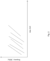
- FIG. 1 shows the time dependence of the frequencies of chirp signals generated with a method according to the state of the art.
- the duration ⁇ of the generated chirp signals is approximately 30 microseconds in a typical arrangement.
- the focal point created on the boundary of successive chirp signals is of insufficient intensity and size to create fluorescent excitation that may be easily detected. Every chirp signal properly deflects the optical beam when the associated acoustic wave substantially fills the illuminated aperture of the deflector.
- the objective of the invention is to provide an acousto-optic scanning method that is free from the disadvantages of the solutions according to the state of the art, in particularto provide an acousto-optic scanning method that enables scanning that is faster than the solutions known of to date.
- the invention is based on the recognition that by creating several successive acoustic chirp signals that are also overlapping in time in the acousto-optic deflector, a fluorescent signal can be generated in the sample with suitable intensity without interrupting the optical beam passing through the acousto-optic deflector.
- the invention is also based on the recognition that by creating several acoustic chirp signals in the acousto-optic deflector forming substantially simultaneously generated superimposed acoustic waves, the optical beam passing through the deflector may be split up into several beams, and deflected in various directions, thereby making it possible to reduce scanning time.
- the optical beam is deflected in such a way that acoustic chirp signals 30 are generated in a first acousto-optic deflector 15 having a Z-axis optical axis and at least one acousto-optic crystal layer 14, and the optical beam 50 is directed into the deflector 15.
- the optical beam 50 contains discrete laser pulses, which pulses have a pulse width in the femtosecond range, and the repetition frequency is preferably in the MHz range.
- laser pulses may be produced using a femtosecond laser pulse source, for example, preferably using a Ti-S laser, as is obvious for a person skilled in the art.
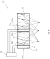
- Figure 3a depicts a schematic cross-sectional view of an embodiment of an acousto-optic deflector 15 containing a single acousto-optic crystal layer 14.
- a single electro-acoustic wave generator 17 adapted for generating acoustic chirp signals 30 is connected to the crystal layer 14, which receives the voltage signals required for generating the acoustic chirp signals 30 from a signal generator 24.
- acoustic chirp signal 30 is understood to mean a variable frequency, periodic acoustic wave signal, the frequency of which continuously increases or decreases with time.
- Chirp signals are either linear or nonlinear depending on whether the change in the frequency of the chirp signal is linear or non-linear over time.
- Linear chirp signals 30 are usually used in acousto-optic deflectors 15 in order to produce stationary focal spots. The use of non-linear chirp signals in acousto-optic deflectors is dealt with in patent document number WO2013/102771A1 , for example.
- the acoustic chirp signal 30 generated by the wave generator 17 passes through the acousto-optic crystal layer 14, due to the effect of which constantly varying refractive index distribution is created along the direction of propagation.
- the deflected portion of the initially collimated optical beam 50 passing through the acousto-optic crystal layer 14 filled with the acoustic chirp signal 30, which is at an angle to the propagation direction of the chirp signal 30 will be either converging (focussed) or diverging on exiting the acousto-optic crystal layer 14 depending on whether the frequency of the chirp signal 30 increases or decreases with time.
- the frequency of the chirp signal 30 created in the crystal layer 14 increases with time, in other words the frequency sweep rate is positive, the deflected portion of the optical beam 50 passing through the crystal layer 14 will be convergent, in other words it will focus.
- the frequency of the chirp signal 30 created in the crystal layer 14 decreases with time, in other words the frequency sweep rate is negative the deflected portion of the optical beam 50 passing through the crystal layer 14 becomes divergent and a focal spot is not formed without the intervention of other focussing optical elements.
- the deflected portion of the optical beam passing through the crystal layer 14 remains collimated, and is merely deflected.
- the degree of deflection of the optical beam 50 in other words the axis of the direction of deflection depends on the difference between the greatest and smallest frequency (i.e. the central frequency) of the chirp signal 30 measurable within the optical aperture, as is obvious for a person skilled in the art.
- the crystal layer 14 is preferably made from a single crystal (such as TeO2, LiNbO3), in which a diffractive index change occurs due to the effect of mechanical stress.
- the electro-acoustic wave generator 17 connected to the acousto-optic crystal layers 14 contains two electrodes 20a, 20b, and a piezoelectric plate 22 arranged therebetween. Of the two electrodes 20a, 20b, the one electrode 20a is connected to the acousto-optic crystal layer 14, while the electrodes 20a, 20b are connected to the signal generator 24. With the voltage connected to the electrodes 20a, 20b being periodically changed by the signal generator 24, the piezoelectric plate 22 is made to vibrate, as is known to a person skilled in the art.
- the piezoelectric plate 22 transfers its vibration to the acousto-optic crystal layer 14 connected to the electrode 20a, and due to the effect of this an acoustic chirp signal 30 is generated and propagated in the acousto-optic crystal layer 14 that corresponds to the transferred vibration.
- the efficiency of the electro-acoustic wave generator 17 is generally optimal in a frequency range determined by a minimum fmin frequency and a maximum fmax frequency, in other words in this range it is most suitable for generating acoustic chirp signals 30.
- the frequency of the chirp signals 30 created by the electro-acoustic wave generator 17 constantly changes, after a period of time their frequency will necessarily reach the lower fmin or upper fmax limit of the frequency range, and the generation of the given chirp signal 30 will be interrupted. Generation may be restarted with a frequency falling in the achievable frequency range, creating a new acoustic chirp signal 30.
- the deflection of the optical beam 50 passing through the acousto-optic crystal layer 14 into the direction defined by the chirp signal 30 is terminated when the final section of the generated chirp signal 30 leaves the illuminated optical aperture.
- the duration of the chirp signal 30 the length of time that elapses between the start of the generation of the chirp signal 30 and the completion of the generation.
- the fmin and fmax frequencies may be preferably determined in such a way, that the acoustic output emitted by the wave generator 17 at the fmin and fmax frequencies drops to a half of the maximum acoustic output that may be emitted by the wave generator 17, in other words the acoustic output emitted by the wave generator 17 between the fmin and fmax frequencies changes to less than 50% of the maximum output.
- the chirp signal 30 duration is preferably longer than the time aperture of the acousto-optic deflector 15, in other words longer than the length of time during which a given phase point (such as the wave front) of the chirp signal 30 passes over the aperture of the deflector 15.
- the deflection of the optical beam 50 is suitable as long as a part of the chirp signal 30 generated by the wave generator 17 completely fills the aperture of the deflector 15. According to empirical experience, a chirp signal 30 with a duration ⁇ before and after complete filling does not deflect the entire aperture for the same amount of time as the time aperture of the deflector, in other words it does not properly deflect the beam.
- the time aperture may even be longer that ⁇ /3, in other words in such a case the deflector deflects the optical beam properly for a duration of less than ⁇ /3.
- the deflector deflects the optical beam properly for a duration of less than ⁇ /3.
- the deflection will not work properly.
- chirp signals 30 with identical duration ⁇ are generated in the deflector 15 at intervals ⁇ , in other words the next chirp signal 30 only starts to be generated after the generation of the previous chirp signal 30 has discontinued.
- an "idle time" equal to two time apertures is created between successively generated chirp signals 30, during which the deflection of the optical beam 50 will be inappropriate.
- acoustic chirp signals 30 are created in the at least one acousto-optic crystal layer 14 of the acousto-optic deflector 15 in such a way that a first acoustic chirp signal 30a with a duration of ⁇ is generated in the acousto-optic crystal layer 14, then within a duration ⁇ counted from the start of the generation of the first acoustic chirp signal 30a a second acoustic chirp signal 30b is generated in the acousto-optic crystal layer 14.
- generation within the duration ⁇ also includes the case when the second acoustic chirp signal 30b is generated substantially simultaneously with the first acoustic chirp signal 30a, and also includes the case when the second acoustic chirp signal 30b is created within the duration ⁇ following the start of the generation of the first acoustic chirp signal 30a.
- chirp signals 30 are generated in the deflector 15 that either partially or entirely overlap each other in time, thereby at least two acoustic chirp signals 30 may be found in the deflector 15 at any time instance.
- the generation of the second acoustic chirp signal 30b is preferably started between the time instances ⁇ /5 and ⁇ /2 following the start of the generation of the first acoustic chirp signal 30a.
- acoustic chirp signals 30 with duration ⁇ with identical sweep rate are generated at time intervals ⁇ /3, in this way the chirp signals 30 partially overlap each other in time.
- the first acoustic chirp signal 30a with duration ⁇ suitably deflects the optical beam 50 between the time instances 5 ⁇ /6 and 7 ⁇ /6 following its generation, in other words for a total duration of ⁇ /3.
- the second acoustic chirp signal 30b starts to suitably deflect the optical beam 50 precisely by the time when the deflecting with the first acoustic chirp signal 30a stops, therefore there will always be a chirp signal 30 in the deflector 15 that sufficiently fills the aperture of the deflector 15 and properly deflects the optical beam 50.
- acoustic chirp signals 30 are created in the deflector 15 using a single electro-acoustic wave generator 17 in such a way that a first voltage signal having a duration of ⁇ is connected to the wave generator 17, with which a first acoustic chirp signal 30a is created in the crystal layer 14, then within an interval of ⁇ following the start of the generation of the first acoustic chirp signal 30a, in other words when the generation of the first acoustic chirp signal 30a is still in process, a second voltage signal is connected to the electro-acoustic wave generator 17, with which a second acoustic chirp signal 30b is created.
- the acoustic chirp signals 30 are created using several electro-acoustic wave generators 17a, 17b connected to the crystal layer 14 in such a way that a first voltage signal having a duration of ⁇ is connected to the first electro-acoustic wave generator 17a with which the first acoustic chirp signal is generated, then within the interval ⁇ after the start of the generation of the first acoustic chirp signal 30a a second voltage signal is connected to a second electro-acoustic wave generator 17b, with which a second acoustic chirp signal 30b is generated.
- At least two acoustic chirp signals 30 are being propagated in the crystal layer 14 of the deflector 15 at every time instance.
- the intermediate frequencies, sweep rates and durations of the chirp signals 30 propagated in the crystal layer 14 may optionally also be different to each other.
- chirp signals 30 having the same positive sweep rate are generated with a duration ⁇ , the intermediate frequencies of which are selected so that the optical beam 50 is focussed along the X-axis using the first acoustic chirp signal 30a at the first point having a first coordinate X1, and focussed at the second point having a second coordinate X2 using the second acoustic chirp signal 30b.
- various different positive sweep rate chirp signals 30 are generated, and the optical beam 50 passing through the acousto-optic crystal layer is focussed to various depths along the Z-axis.
- the optical beam 50 is not only focussed along the Z-axis at various points, but also at various points along the X-axis.
- the crystal layer 14 containing the positive sweep rate chirp signals 30 is itself capable of focussing the deflected portion of the optical beam 50, as is known to a person skilled in the art, however, the range of focus that may be achieved with this is limited.
- the sweep rate of the chirp signals is negative.
- other optical elements may participate in the focussing of the optical beam 50 (such as an objective arranged after the deflector 15).
- the deflected portion of the optical beam 50 exiting the crystal layer 14 that is diverging and/or converging (or optionally parallel) according to the algebraical signs of the sweep rates of the acoustic chirp signals 30 is focussed using an optical element arranged after the deflector 15, preferably with an objective.
- the depth of the focal points in the case of these embodiments also is controlled using the deflector 15, in other words with the sweep rate of the chirp signals 30, in this way the focussing of the optical beam 50 takes place substantially with the deflector 15.
- a superimposed acoustic wave 31 with a duration ⁇ ' is generated in such a way that the generation of the second acoustic chirp signal 30b having a duration of ⁇ is started substantially simultaneously with the generation of the first acoustic chirp signal 30a having a duration of ⁇ .
- superimposed acoustic wave 31 means an acoustic wave consisting of several acoustic chirp signals 30 in which the chirp signals 30 completely overlap both in time and space, in other words their durations, temporal and spatial endpoints are the same.
- the duration ⁇ ' of the superimposed acoustic wave 31 is the same as the duration ⁇ of the chirp signals 30 which make up it.
- Such a superimposed acoustic wave 31 may be created with a single wave generator 17 in such a way that the voltage signals individually creating the chirp signals 30 forming the superimposed acoustic wave 31 are applied to the electrodes 20a, 20b simultaneously.
- the superimposed acoustic wave 31 is generated using several wave generators 17, all of which are connected to the crystal layer 14 (see figures 3b and 3c ).
- a chirp signal 30 is simultaneously created with each wave generator 17 in the crystal layer 14, thereby creating the superimposed acoustic wave 31.
- the chirp signals 30 forming the superimposed acoustic wave 31 separately deflect the optical beam 50 at the same time in accordance with their frequency profile (sweep rate and intermediate frequency).
- the deflection also includes the deflection of the individual portions of the optical beam 50, in other words meaning the focussing of the optical beam 50, or, optionally the creation of a diverging or collimated beam.
- a superimposed acoustic wave 31 is generated containing positive sweep rate chirp signals 30, with which the optical beam 50 is divided into at least two beams along the X-axis and deflected in difference directions.
- Figure 5a shows the spatial distribution of the frequency of the chirp signals 30 forming the superimposed acoustic wave 31 created in the acousto-optic crystal layer 14 according to figure 3a .
- the frequency difference between any two points at an identical distance from each other is constant, in other words a constant, linear function may be fitted to the distance-frequency function.
- a non-linear frequency function may be created using another type of control (in order to move the focal point along a given trajectory, for example).
- several superimposed acoustic waves 31 are created successively in at least one acousto-optic crystal layer 14 of the acousto-optic deflector 15 in such a way that a first superimposed acoustic wave 31a with duration ⁇ ' is generated in the acousto-optic crystal layer 14, then within a duration ⁇ ' counted from the start of the generation of the first superimposed acoustic wave 31a a second superimposed acoustic wave 31b is generated in the acousto-optic crystal layer 14.
- the generation of the second superimposed acoustic wave 31b is preferably started between the time instances ⁇ '/5 and ⁇ '/2 following the start of the generation of the first superimposed acoustic wave 31a.
- the duration ⁇ ' superimposed acoustic waves 31 are generated at intervals ⁇ '/3, in this way the superimposed acoustic waves 31 partially overlap each other in time.
- more than two superimposed acoustic waves 31 are generated successively in such a way that a third superimposed acoustic wave 31c is generated within a duration ⁇ ' following the start of the generation of the second superimposed acoustic wave 31b in such a way that the generation of the third superimposed acoustic wave 31c is started between the time instances ⁇ '/2 and 4 ⁇ '/5 following the start of the generation of the first superimposed acoustic wave 31a, preferably at the time instance 2 ⁇ '/3.
- the acousto-optic deflector 15' contains at least two acousto-optic crystal layers 14a, 14b, and at least one acousto-optic wave generator 17a, 17b is connected to each of them, and the neighbouring crystal layers 14a, 14b are separated by an acoustic isolator 18 (see figures 3b , 3c , 4b , 4c ).
- the thickness of the electro-acoustic wave generators 17 arranged between the acousto-optic crystal layers 14 is preferably less than 100 ⁇ m in order to obscure as little as possible the optical beam 50 passing through, but, naturally, embodiments are conceivable where the thickness of the wave generators 17 arranged between the crystal layers 14 is greater that 100 ⁇ m. Implicitly, the acoustic isolators 18 are designed to have a minimal thickness. Optionally an embodiment is conceivable in the case of which the deflector 15' contains a number N of equal thickness crystal layers 14.
- the acoustic chirp signal 30 may be generated in the acousto-optic deflector 15' over the entire aperture of the acousto-optic deflector 15' in 1/N of the time as compared to the time in the case of an acousto-optic deflector 15 containing a single (undivided) acousto-optic crystal layer 14 with the same size of aperture.
- the function of the acoustic isolator 18 is to prevent the wave generator 17 connected to the neighbouring crystal layer 14 from generating an acoustic wave in another crystal layer 14.
- the acoustic isolator 18 contains an air gap or sound-absorbing material.
- the chirp signals 30 generated with the wave generator 17 are unable to propagate in the air gap filled with rarefied gas, such as air, or in the absorbent material, due to this the chirp signals 30 propagating in the acousto-optic crystal layer 14 can be prevented from passing over into the neighbouring acousto-optic crystal layer 14 separated by the acoustic isolator 18.
- a first superimposed acoustic wave containing several chirp signals 30 is generated in the acousto-optic crystal layer 14a using the first electro-acoustic wave generator 17a connected thereto, and a second superimposed acoustic wave containing several chirp signals 30 is generated in the second acousto-optic crystal layer 14b using the second electro-acoustic wave generator 17b connected thereto.
- the first electro-acoustic wave generator 17a contains several electro-acoustic wave generator units 17a' and the second acoustic wave generator 17b also contains several electro-acoustic wave generator units 17b'.
- wave generator unit 17a', 17b' is understood to mean a device connected to the crystal layer that functions as a wave generator 17, in other words that is able to generate an acoustic chirp signal 30 in the crystal layer 14.
- the individual chirp signals 30 forming the superimposed acoustic waves 31 are created using the individual electro-acoustic wave generator units 17a', 17b'.
- a superimposed acoustic wave is created in the acousto-optic deflector 15' containing several acousto-optic crystal layers 14 that fills its entire aperture in such a way that in the individual acousto-optic crystal layers 14a, 14b the spatial section of the superimposed acoustic wave 31 falling on the given acousto-optic crystal layer 14a, 14b is created using the electro-acoustic wave generator 17a, 17b belonging to the given acousto-optic crystal layer 14a, 14b.
- superimposed acoustic wave signals 31 independent of each other are created in the various acousto-optic crystal layers 14 of the deflector 15' using the electro-acoustic wave generators 17a, 17b belonging to the individual acousto-optic crystal layers 14a, 14b, in other words superimposed acoustic waves 31 that together do not form a superimposed acoustic wave 31 that fills the entire aperture of the deflector 15'. Therefore, in the case of this embodiment optionally the superimposed acoustic waves 31 generated in the various crystal layers 14a, 14b may even contain different numbers of chirp signals 30 (see figure 5c ).
- the superimposed acoustic wave 31 is created using the individual electro-acoustic wave generators 17a, 17b connected to each of the crystal layers 14a, 14b in such a way that separate superimposed voltage signals are connected to the electro-acoustic wave generators 17a, 17b, in other words the voltage signal components creating the chirp signals 30 forming the superimposed acoustic wave 31 are connected substantially simultaneously to the electro-acoustic wave generators 17a, 17b.
- the electro-acoustic wave generators 17a, 17b connected to the crystal layers 14a, 14b contain several wave generator units 17a', 17b', and the individual chirp signals 30 forming the superimposed acoustic waves 31 are created using the individual electro-acoustic wave generators 17a', 17b'.
- the method according to the invention is suitable for the very short duration illumination of a biological samples 40, in particular nerve cells, which involves focussing the optical beam 50 onto the sample 40 at one or several points, in this way inducing two-photon emission, then by moving the one or more focal points the sample 40 is completely scanned.
- Figure 6 shows a schematic view of the main elements of an acousto-optic scanning system 10 having an optical axis along a Z-axis adapted for performing the method according to the invention.
- the acousto-optic scanning system 10 preferably contains a light source adapted for creating an optical beam 50, a deflecting element 12 adapted for deflecting the optical beam 50 along the X-axis perpendicular to the Z-axis, and an acousto-optic deflector 15 having at least one acousto-optic crystal layer 14 adapted for deflecting the optical beam 50 along the X-axis perpendicular to the Z- and Y-axes.
- a signal generator 24 adapted for producing voltage signals creating acoustic chirp signals 30 is connected to the wave generator 17 of the deflector 15.
- the deflecting element 12 preferably contains a galvanometric scanning mirror, and/or one or two acousto-optic deflectors 35, with which the optical beam 50 passing through the deflecting element 12 may be deflected along the Y-axis, as is known to a person skilled in the art (e.g. patent number US 8,559,085 ).
- the deflector 35 is also controlled with the signal generator 24.
- an optical beam 50 preferably a laser beam is produced and emitted with the light source 52, then the emitted optical beam 50 is transmitted to the deflecting element 12.
- optical elements that improve the characteristics of the optical beam 50 may be placed between the light source 52 and the deflecting element 12, such as a Faraday isolator, dispersion compensating elements, a laser beam stabilising module, a beam broadening device, an angular dispersion compensation device, etc., as is obvious for a person skilled in the art.
- the optical beam 50 is deflected along the Y-axis perpendicular to the optical axis of the optical beam 50.
- f t f 0 + f ⁇ ⁇ f 0 ⁇ t where ⁇ is the signal repetition period - i.e.
- f(0) is the initial and f(T) is the final chirp frequency, as is known to a person skilled in the art.
- f(0) is the initial and f(T) is the final chirp frequency, as is known to a person skilled in the art.
- a DA4300-12-4M-PCI signal generator with four output channels and one trigger input and one trigger output in combination with a power amplifier may be used as the signal generator 24, but naturally other types of signal generator are conceivable.
- the optical beam 50 exiting from the deflecting element 12 passes into the deflector 15, with which the optical beam 50 is deflected.
- a superimposed acoustic wave 31 containing at least two chirp signals 30 preferably with the same sweep rate are created in the acousto-optic crystal layer 14 using one or more electro-acoustic wave generators 17 controlled by a signal generator 24 and connected to the acousto-optic crystal layer 14, in this way the optical beam 50 is split into at least two beams, and is deflected in different directions along the X-axis.
- the chirp signals 30 forming the superimposed acoustic wave 31 deflect the separated portions of the optical beam 50 separately, in accordance with their frequency profile.
- the positive sweep rate chirp signals 30 focus the parts of the optical beam 50 at various points within the X-Z plane.
- the negative sweep rate chirp signals 30 make the initially parallel optical beam 50 diverging, in other words a focal point is not created.
- the diverging or converging beams exiting the acousto-optic deflector 15 are focussed with an optical element, preferably an objective, arranged after the acousto-optic deflector 15.
- the X-axis coordinate of the focal points may be changed with the intermediate frequency of the chirp signal 30, and the Z-axis coordinate of the focal point may be changed with the sweep rate of the chirp signal (see figures 5a, 5b, 5c ).
- the optical beam 50 passing into the acousto-optic deflector 15 is displaced along the Y-axis perpendicular to the X- and Z-axes using the deflecting element 12, as a consequence of which the focal points move at the same time along straight lines parallel to each other.
- a 2-dimensional surface or optional slice (planar cross-section) of the sample 40 can be scanned (see figure 7 ).
- the displacement along the Y-axis may be continuous or intermittent. In the case of the former the focal points describe continuous straight lines during the displacement, while in the case of the latter the focal points create series of points to which straight lines may be fitted.
- the optical beam 50 deflected by the deflector 15 in one or more directions is continuously displaced (drifts) along the X-axis, as is known to a person skilled in the art. Due to the effect of the drift, the focal points will move along straight lines at an angle to the X- and Y-axes, which are preferably taken into account during scanning.
- the aforementioned drift may be eliminated in such a way, for example, by using at least two acousto-optic deflectors 15 arranged one after the other in order to focus the parts of the optical beam 50 at several points, in which superimposed acoustic waves 31 are generated that have the same frequency profile, but preferably a different intermediate frequency, and that move in opposite directions.
- scanning is performed in three dimensions with the method according to the invention in such a way that the optical beam 50 passing through the acousto-optic deflector 15 is focussed at different depths along the Z-axis by suitably selecting the sweep rate of the chirp signals 30 forming the superimposed acoustic wave 31.
- this embodiment by displacing the optical beam 50 along the Y-axis the focal points will move along a 3-dimensional surface.
- the coordinates of the focal points along the X- and Y-axes are controlled by suitably selecting the intermediate frequencies and sweep rates of the chirp signals 30 in such a way that their deflection along the Y-axis, in other words during scanning, falls on the 3-dimensional surface of the sample 40.
- the coordinates of the focal points along the Z-axis are continuously varied during scanning to correspond with the surface of the sample 40 to be examined.
- the deflecting element 12 of the scanning system 10 contains two acousto-optic deflectors Y1, Y2 deflecting along the Y-axis, and two acousto-optic deflectors X1, X2 deflecting along the X-axis.
- a chirp signal 30 with the same sweep rate is connected to each of the deflectors Y1, Y2 of the deflecting element 12, and to the deflector X1 deflecting along the X-axis.
- a superimposed acoustic wave containing several chirp signals 30 is created in the deflector X2, in the case of which the sweep rate of the chirp signals 30 is the same as the sweep rate of the chirp signals 30 of the superimposed acoustic waves 31 created in the deflectors Y1, Y2, X1.
- Chirp signals 30 preferably travelling in opposite directions are generated in the acousto-optic deflectors deflecting along the same axis, in other words, for example, the chirp signals 30 of the deflectors Y1 and Y2 travel in directions opposite to each other.
- the focal points created will not drift, neither along the X-axis nor the Y-axis.
- the focal points are focussed along the Y-axis to the locations determined in accordance with the intermediate frequency difference of the chirp signals 30 created in the deflector pair Y1 and Y2, therefore the point grid shown in figure 8 is created during scanning.
- the points (focal points) of the point grid created are located at the same depth Z, therefore the scanning takes place in constant planes Z.
- the sweep rate of the chirp signals 30 in each of the deflectors X1, X2, Y1, Y2 is changed, and scanning is performed once again in a plane parallel to the previous plane at a different depth. This allows a 3-dimensional sample to be completely scanned across planes.
- Another preferred embodiment differs from the above embodiment only in that a chirp signal 30 is connected to the deflector Y2 with a different sweep rate to the sweep rate of the chirp signals 30 connected to the deflectors X1, X2, Y1, due to the effect of which the focal points will drift along the Y-axis.
- a grid will be drawn consisting of sections in the Y direction (see figure 9 ).
- a acousto-optic deflector 15 may be used that contains at least two acousto-optic crystal layers 14a, 14b preferably separated by acoustic isolators 18.
- a first superimposed acoustic wave 31a containing several chirp signals 30 is created in a first acousto-optic crystal layer 14a using a first electro-acoustic wave generator 17a connected to the first acousto-optic crystal layer 14a
- a second superimposed acoustic wave 31b containing several chirp signals 30 is created in a second acousto-optic crystal layer 14b using a second acousto-optic wave generator 17b connected to the second acousto-optic crystal layer 14b and arranged between the first acousto-optic crystal layer 14a and the second acousto-optic crystal layer 14b.
Landscapes
- Physics & Mathematics (AREA)
- Nonlinear Science (AREA)
- General Physics & Mathematics (AREA)
- Optics & Photonics (AREA)
- Health & Medical Sciences (AREA)
- Analytical Chemistry (AREA)
- Chemical & Material Sciences (AREA)
- Nuclear Medicine, Radiotherapy & Molecular Imaging (AREA)
- Life Sciences & Earth Sciences (AREA)
- Biochemistry (AREA)
- General Health & Medical Sciences (AREA)
- Immunology (AREA)
- Pathology (AREA)
- Optical Modulation, Optical Deflection, Nonlinear Optics, Optical Demodulation, Optical Logic Elements (AREA)
Claims (14)
- Verfahren zum Abtasten mit einem optischen Strahl (50) unter Verwendung eines ersten akusto-optischen Deflektors (15, 15') mit einer optischen Achse entlang einer Z-Achse und mindestens einer akusto-optischen Kristallschicht (14), Lenken des optischen Strahls (50) in den ersten akusto-optischen Deflektor (15, 15') und Ablenken des optischen Strahls (50) entlang einer X-Achse, die senkrecht zu der Z-Achse ist, mittels des ersten akusto-optischen Deflektors (15, 15'), während eine Vielzahl von akustischen Chirp-Signalen (30) in der mindestens einen akusto-optischen Kristallschicht (14) des akusto-optischen Deflektors (15, 15') erzeugt wird
gekennzeichnet durch
Verwenden eines einzelnen elektro-akustischen Wellengenerators (17), der mit der Kristallschicht (14) verbunden ist, durch Anlegen eines ersten Spannungssignals mit einer Dauer von τ an den elektro-akustischen Wellengenerator (17), wodurch ein erstes akustisches Chirp-Signal (30a) erzeugt wird, dann Anlegen eines zweiten Spannungssignals an den elektro-akustischen Wellengenerator (17) innerhalb einer Dauer τ nach dem Beginn der Erzeugung des ersten akustischen Chirp-Signals (30a), wodurch ein zweites akustisches Chirp-Signal (30b) erzeugt wird, wobei die akustischen Chirp-Signale (30a, 30b) einander in der Kristallschicht (14) entweder teilweise oder vollständig überlappen. - Verfahren nach Anspruch 1, gekennzeichnet durch Beginnen des Erzeugens des zweiten akustischen Chirp-Signals (30b) zwischen den Zeitpunkten τ/5 und τ/2 nach dem Beginn der Erzeugung des ersten akustischen Chirp-Signals (30a), vorzugsweise zu dem Zeitpunkt τ/3.
- Verfahren nach einem der Ansprüche 1 oder 2, gekennzeichnet durch Erzeugen eines dritten akustischen Chirp-Signals (30c) innerhalb eines Zeitraums von τ nach dem Beginn der Erzeugung des zweiten akustischen Chirp-Signals (30b).
- Verfahren nach Anspruch 3, gekennzeichnet durch Beginnen des Erzeugens des dritten akustischen Chirp-Signals (30c) zwischen den Zeitpunkten τ/2 und 4τ/5 nach dem Beginn der Erzeugung des ersten akustischen Chirp-Signals (30a), vorzugsweise zu dem Zeitpunkt 2τ/3.
- Verfahren nach einem der Ansprüche 1 bis 4, gekennzeichnet durch Erzeugen von akustischen Chirp-Signalen (30) mit verschiedenen Abtastraten und Fokussieren des durch die akusto-optische Kristallschicht (14) hindurchtretenden optischen Strahls (50) in verschiedenen Tiefen entlang der Z-Achse.
- Verfahren nach einem der Ansprüche 1 bis 5, gekennzeichnet durch Fokussieren der aus der akusto-optischen Kristallschicht (14) austretenden Strahlen, die gemäß den Vorzeichen der Abtastraten der akustischen Chirp-Signale (30) divergieren und/oder konvergieren, unter Verwendung eines optischen Elements, vorzugsweise eines Objektivs, das nach dem ersten akusto-optischen Deflektor (15) angeordnet ist.
- Verfahren nach einem der Ansprüche 1 bis 6, gekennzeichnet durch Fokussieren des optischen Strahls (50) entlang der X-Achse unter Verwendung des ersten akustischen Chirp-Signals (30a) auf einen ersten Punkt mit einer ersten Koordinate X1 und unter Verwendung des zweiten akustischen Chirp-Signals (30b) zum Fokussieren des optischen Strahls (50) auf einen zweiten Punkt mit einer zweiten Koordinate X2.
- Verfahren nach einem der Ansprüche 1 bis 7, gekennzeichnet durch Erzeugen einer überlagerten akustischen Welle (31) durch Erzeugen des zweiten akustischen Chirp-Signals (30b) im Wesentlichen gleichzeitig mit dem ersten akustischen Chirp-Signal (30a) und Aufteilen des optischen Strahls (50) in zwei Strahlen entlang der X-Achse unter Verwendung der überlagerten akustischen Welle (31) und Ablenken derselben in verschiedene Richtungen.
- Verfahren nach Anspruch 8, gekennzeichnet durch Erzeugen mehrerer überlagerter akustischer Wellen (31) nacheinander in der akusto-optischen Kristallschicht (14) durch- Erzeugen einer ersten überlagerten akustischen Welle (31a) mit einer Dauer von τ' in der akusto-optischen Kristallschicht (14), dann- Erzeugen einer zweiten überlagerten akustischen Welle (31b) innerhalb eines Zeitraums von τ' nach dem Beginn der Erzeugung der ersten überlagerten akustischen Welle (31a).
- Verfahren nach Anspruch 9, gekennzeichnet durch Beginnen des Erzeugens der zweiten überlagerten akustischen Welle (31b) zwischen den Zeitpunkten τ'/5 und τ'/2 nach dem Beginn der Erzeugung der ersten überlagerten akustischen Welle (31a), vorzugsweise zu dem Zeitpunkt τ'/3.
- Verfahren nach einem der Ansprüche 8 bis 10, gekennzeichnet durch Erzeugen einer dritten überlagerten akustischen Welle (31c) innerhalb eines Zeitraums von τ' nach dem Beginn der Erzeugung der zweiten überlagerten akustischen Welle (31b).
- Verfahren nach Anspruch 11, gekennzeichnet durch Beginnen des Erzeugens einer dritten überlagerten akustischen Welle (31c) zwischen den Zeitpunkten τ'/2 und 4τ'/5 nach dem Beginn der Erzeugung der ersten überlagerten akustischen Welle (31a), vorzugsweise zu dem Zeitpunkt 2τ'/3.
- Verfahren nach einem der Ansprüche 8 bis 12, dadurch gekennzeichnet, dass der akusto-optische Deflektor (15') mindestens zwei akusto-optische Kristallschichten (14a, 14b) enthält, und Erzeugen der ersten überlagerten akustischen Welle (31a) in einer ersten akusto-optischen Kristallschicht (14a) unter Verwendung eines ersten elektro-akustischen Wellengenerators (17a), der mit der ersten akusto-optischen Kristallschicht (14a) verbunden ist, und Erzeugen einer zweiten überlagerten akustischen Welle (31b) in einer zweiten akusto-optischen Kristallschicht (14b) unter Verwendung eines zweiten elektro-akustischen Wellengenerators (17b), der mit der zweiten akusto-optischen Kristallschicht (14b) verbunden ist.
- Verfahren nach einem der Ansprüche 1 bis 13, dadurch gekennzeichnet, dass der elektro-akustische Wellengenerator (17), der mit der mindestens einen akusto-optischen Kristallschicht (14) verbunden ist, zwei Elektroden (20a, 20b) und eine dazwischen angeordnete piezoelektrische Platte (22) enthält, und eine Elektrode (20a) der zwei Elektroden (20a, 20b) mit der akusto-optischen Kristallschicht (14) verbunden ist.
Applications Claiming Priority (2)
| Application Number | Priority Date | Filing Date | Title |
|---|---|---|---|
| HUP1800286 | 2018-08-14 | ||
| PCT/HU2019/050039 WO2020035710A1 (en) | 2018-08-14 | 2019-08-14 | Method of scanning an optical beam using an acousto-optic deflector driven by chirped acoustic signals |
Publications (3)
| Publication Number | Publication Date |
|---|---|
| EP3837580A1 EP3837580A1 (de) | 2021-06-23 |
| EP3837580B1 true EP3837580B1 (de) | 2024-08-07 |
| EP3837580C0 EP3837580C0 (de) | 2024-08-07 |
Family
ID=89720055
Family Applications (1)
| Application Number | Title | Priority Date | Filing Date |
|---|---|---|---|
| EP19794627.0A Active EP3837580B1 (de) | 2018-08-14 | 2019-08-14 | Verfahren zum abtasten eines optischen strahls unter verwendung eines akustooptischen ablenkers mit ansteuerung durch gechirpte akustische signale |
Country Status (7)
| Country | Link |
|---|---|
| US (1) | US11927873B2 (de) |
| EP (1) | EP3837580B1 (de) |
| JP (1) | JP7444161B2 (de) |
| CN (1) | CN112752993B (de) |
| CA (1) | CA3109445A1 (de) |
| HU (1) | HUE067949T2 (de) |
| WO (1) | WO2020035710A1 (de) |
Families Citing this family (3)
| Publication number | Priority date | Publication date | Assignee | Title |
|---|---|---|---|---|
| CN115963058A (zh) * | 2021-10-13 | 2023-04-14 | 北京鉴知技术有限公司 | 扫频激光器和光学相干层析成像系统 |
| CN115963060B (zh) * | 2021-10-13 | 2026-04-14 | 北京鉴知技术有限公司 | 扫频激光器及其控制方法、光学相干层析成像系统 |
| CN115519243B (zh) * | 2022-11-25 | 2023-03-21 | 武汉铱科赛科技有限公司 | 一种激光脉冲时空相关定位扫描方法、装置及系统 |
Family Cites Families (19)
| Publication number | Priority date | Publication date | Assignee | Title |
|---|---|---|---|---|
| US3851951A (en) * | 1974-01-16 | 1974-12-03 | Isomet Corp | High resolution laser beam recorder with self-focusing acousto-optic scanner |
| US4355869A (en) * | 1980-05-29 | 1982-10-26 | Rockwell International Corporation | Self scanned optical Fourier transform arrangement |
| JPS5918933A (ja) * | 1982-07-23 | 1984-01-31 | Hitachi Ltd | レ−ザビ−ム偏向方法 |
| JPS6118932A (ja) * | 1984-07-05 | 1986-01-27 | Sony Corp | レーザー光偏向装置 |
| DE3750694T2 (de) * | 1986-11-28 | 1995-02-23 | Fuji Photo Film Co Ltd | Optische Ablenkeinrichtung. |
| US5717401A (en) * | 1995-09-01 | 1998-02-10 | Litton Systems, Inc. | Active recognition system with optical signal processing |
| US5805743A (en) * | 1995-10-30 | 1998-09-08 | Minolta Co., Ltd. | Optical deflector and scanning optical system provided with the optical deflector |
| US5852702A (en) * | 1996-02-28 | 1998-12-22 | Minolta Co., Ltd. | Thin film optical waveguide and optical deflecting device |
| IL140309A0 (en) * | 2000-12-14 | 2002-02-10 | Yeda Res & Dev | Acousto-optic scanner with fast non-linear scan |
| JP4472931B2 (ja) * | 2001-05-03 | 2010-06-02 | ケーエルエー−テンカー コーポレイション | 光ビームに試料全体を走査させるためのシステムおよび方法 |
| US6809808B2 (en) | 2002-03-22 | 2004-10-26 | Applied Materials, Inc. | Wafer defect detection system with traveling lens multi-beam scanner |
| HU0800781D0 (en) | 2008-12-31 | 2009-03-02 | Femtonics Kft | Focusing system comprising acousto-optic deflectors for focusing an electromagnetic beam |
| CN101738815B (zh) | 2009-12-03 | 2012-05-09 | 深圳先进技术研究院 | 激光三维扫描装置和激光三维扫描方法 |
| GB201006679D0 (en) * | 2010-04-21 | 2010-06-09 | Ucl Business Plc | Methods and apparatus to control acousto-optic deflectors |
| CN103299234B (zh) * | 2010-11-04 | 2016-11-02 | 麦克罗尼克迈达塔有限责任公司 | 通过在扫描方向上具有扩展场的声光偏转器(aod)来扫描二维刷的方法和装置 |
| GB201106787D0 (en) * | 2011-04-20 | 2011-06-01 | Ucl Business Plc | Methods and apparatus to control acousto-optic deflectors |
| ES2732423T3 (es) | 2012-01-05 | 2019-11-22 | Femtonics Kft | Método para escanear a lo largo de una trayectoria de escaneo continuo con un sistema de escáner |
| HUE070511T2 (hu) | 2013-11-08 | 2025-06-28 | Inst Nat Sante Rech Med | Állítható sebességû gyors lézeres pásztázó összeállítás és ahhoz kapcsolódó kétfoton-mikroszkóp |
| HUP1500264A2 (en) | 2015-06-01 | 2018-05-02 | Femtonics Kft | Layered structured acousto-optical deflector and method for optical beam deflection with deflectior |
-
2019
- 2019-08-14 WO PCT/HU2019/050039 patent/WO2020035710A1/en not_active Ceased
- 2019-08-14 US US17/268,199 patent/US11927873B2/en active Active
- 2019-08-14 HU HUE19794627A patent/HUE067949T2/hu unknown
- 2019-08-14 CA CA3109445A patent/CA3109445A1/en active Pending
- 2019-08-14 EP EP19794627.0A patent/EP3837580B1/de active Active
- 2019-08-14 JP JP2021507477A patent/JP7444161B2/ja active Active
- 2019-08-14 CN CN201980062968.8A patent/CN112752993B/zh active Active
Also Published As
| Publication number | Publication date |
|---|---|
| WO2020035710A1 (en) | 2020-02-20 |
| EP3837580A1 (de) | 2021-06-23 |
| CN112752993A (zh) | 2021-05-04 |
| HUE067949T2 (hu) | 2024-11-28 |
| CN112752993B (zh) | 2024-07-09 |
| CA3109445A1 (en) | 2020-02-20 |
| US11927873B2 (en) | 2024-03-12 |
| JP2021535420A (ja) | 2021-12-16 |
| JP7444161B2 (ja) | 2024-03-06 |
| EP3837580C0 (de) | 2024-08-07 |
| US20210318590A1 (en) | 2021-10-14 |
Similar Documents
| Publication | Publication Date | Title |
|---|---|---|
| JP5213861B2 (ja) | イメージング装置及び方法 | |
| CN101738815B (zh) | 激光三维扫描装置和激光三维扫描方法 | |
| US7227127B2 (en) | High speed microscope with three-dimensional laser beam scanning including acousto-optic deflector for controlling the lateral position and collimation of the light beam | |
| EP3207418B1 (de) | Verfahren zur analyse einer probe mit nichtlinearer mikroskoptechnik und zugehöriges nichtlineares mikroskop | |
| US11927873B2 (en) | Method of scanning an optical beam using an acousto-optic deflector driven by chirped acoustic signals | |
| EP2800995B1 (de) | Verfahren zum scannen entlang einer durchgehenden scanningtrajektorie mit einem scannersystem | |
| WO2009087392A1 (en) | Optical beam deflection apparatus and methods | |
| JP2021529349A (ja) | プログラム可能な多点照明器、共焦点フィルタ、共焦点顕微鏡、および共焦点顕微鏡を操作する方法 | |
| EP3304184B1 (de) | Akusto-optischer deflektor mit schichtstruktur und verfahren zum ablenken eines optischen strahls mit solch einem deflektor | |
| EP3066512B1 (de) | Laserabtastsystem und zugehöriges zwei-photonen-mikroskop | |
| EP4180871A1 (de) | Lithografischer laserschreiber mit mehrkopfabtastung |
Legal Events
| Date | Code | Title | Description |
|---|---|---|---|
| STAA | Information on the status of an ep patent application or granted ep patent |
Free format text: STATUS: UNKNOWN |
|
| STAA | Information on the status of an ep patent application or granted ep patent |
Free format text: STATUS: THE INTERNATIONAL PUBLICATION HAS BEEN MADE |
|
| PUAI | Public reference made under article 153(3) epc to a published international application that has entered the european phase |
Free format text: ORIGINAL CODE: 0009012 |
|
| STAA | Information on the status of an ep patent application or granted ep patent |
Free format text: STATUS: REQUEST FOR EXAMINATION WAS MADE |
|
| 17P | Request for examination filed |
Effective date: 20210219 |
|
| AK | Designated contracting states |
Kind code of ref document: A1 Designated state(s): AL AT BE BG CH CY CZ DE DK EE ES FI FR GB GR HR HU IE IS IT LI LT LU LV MC MK MT NL NO PL PT RO RS SE SI SK SM TR |
|
| DAV | Request for validation of the european patent (deleted) | ||
| DAX | Request for extension of the european patent (deleted) | ||
| STAA | Information on the status of an ep patent application or granted ep patent |
Free format text: STATUS: EXAMINATION IS IN PROGRESS |
|
| 17Q | First examination report despatched |
Effective date: 20220322 |
|
| GRAP | Despatch of communication of intention to grant a patent |
Free format text: ORIGINAL CODE: EPIDOSNIGR1 |
|
| STAA | Information on the status of an ep patent application or granted ep patent |
Free format text: STATUS: GRANT OF PATENT IS INTENDED |
|
| INTG | Intention to grant announced |
Effective date: 20240306 |
|
| GRAS | Grant fee paid |
Free format text: ORIGINAL CODE: EPIDOSNIGR3 |
|
| GRAA | (expected) grant |
Free format text: ORIGINAL CODE: 0009210 |
|
| STAA | Information on the status of an ep patent application or granted ep patent |
Free format text: STATUS: THE PATENT HAS BEEN GRANTED |
|
| AK | Designated contracting states |
Kind code of ref document: B1 Designated state(s): AL AT BE BG CH CY CZ DE DK EE ES FI FR GB GR HR HU IE IS IT LI LT LU LV MC MK MT NL NO PL PT RO RS SE SI SK SM TR |
|
| REG | Reference to a national code |
Ref country code: GB Ref legal event code: FG4D |
|
| REG | Reference to a national code |
Ref country code: CH Ref legal event code: EP |
|
| REG | Reference to a national code |
Ref country code: IE Ref legal event code: FG4D |
|
| REG | Reference to a national code |
Ref country code: DE Ref legal event code: R096 Ref document number: 602019056646 Country of ref document: DE |
|
| U01 | Request for unitary effect filed |
Effective date: 20240828 |
|
| U07 | Unitary effect registered |
Designated state(s): AT BE BG DE DK EE FI FR IT LT LU LV MT NL PT RO SE SI Effective date: 20240906 |
|
| U20 | Renewal fee for the european patent with unitary effect paid |
Year of fee payment: 6 Effective date: 20240830 |
|
| REG | Reference to a national code |
Ref country code: HU Ref legal event code: AG4A Ref document number: E067949 Country of ref document: HU |
|
| PG25 | Lapsed in a contracting state [announced via postgrant information from national office to epo] |
Ref country code: NO Free format text: LAPSE BECAUSE OF FAILURE TO SUBMIT A TRANSLATION OF THE DESCRIPTION OR TO PAY THE FEE WITHIN THE PRESCRIBED TIME-LIMIT Effective date: 20241107 |
|
| PG25 | Lapsed in a contracting state [announced via postgrant information from national office to epo] |
Ref country code: GR Free format text: LAPSE BECAUSE OF FAILURE TO SUBMIT A TRANSLATION OF THE DESCRIPTION OR TO PAY THE FEE WITHIN THE PRESCRIBED TIME-LIMIT Effective date: 20241108 Ref country code: PL Free format text: LAPSE BECAUSE OF FAILURE TO SUBMIT A TRANSLATION OF THE DESCRIPTION OR TO PAY THE FEE WITHIN THE PRESCRIBED TIME-LIMIT Effective date: 20240807 |
|
| PG25 | Lapsed in a contracting state [announced via postgrant information from national office to epo] |
Ref country code: IS Free format text: LAPSE BECAUSE OF FAILURE TO SUBMIT A TRANSLATION OF THE DESCRIPTION OR TO PAY THE FEE WITHIN THE PRESCRIBED TIME-LIMIT Effective date: 20241207 |
|
| PG25 | Lapsed in a contracting state [announced via postgrant information from national office to epo] |
Ref country code: HR Free format text: LAPSE BECAUSE OF FAILURE TO SUBMIT A TRANSLATION OF THE DESCRIPTION OR TO PAY THE FEE WITHIN THE PRESCRIBED TIME-LIMIT Effective date: 20240807 |
|
| PG25 | Lapsed in a contracting state [announced via postgrant information from national office to epo] |
Ref country code: RS Free format text: LAPSE BECAUSE OF FAILURE TO SUBMIT A TRANSLATION OF THE DESCRIPTION OR TO PAY THE FEE WITHIN THE PRESCRIBED TIME-LIMIT Effective date: 20241107 Ref country code: ES Free format text: LAPSE BECAUSE OF FAILURE TO SUBMIT A TRANSLATION OF THE DESCRIPTION OR TO PAY THE FEE WITHIN THE PRESCRIBED TIME-LIMIT Effective date: 20240807 |
|
| PG25 | Lapsed in a contracting state [announced via postgrant information from national office to epo] |
Ref country code: RS Free format text: LAPSE BECAUSE OF FAILURE TO SUBMIT A TRANSLATION OF THE DESCRIPTION OR TO PAY THE FEE WITHIN THE PRESCRIBED TIME-LIMIT Effective date: 20241107 Ref country code: PL Free format text: LAPSE BECAUSE OF FAILURE TO SUBMIT A TRANSLATION OF THE DESCRIPTION OR TO PAY THE FEE WITHIN THE PRESCRIBED TIME-LIMIT Effective date: 20240807 Ref country code: NO Free format text: LAPSE BECAUSE OF FAILURE TO SUBMIT A TRANSLATION OF THE DESCRIPTION OR TO PAY THE FEE WITHIN THE PRESCRIBED TIME-LIMIT Effective date: 20241107 Ref country code: IS Free format text: LAPSE BECAUSE OF FAILURE TO SUBMIT A TRANSLATION OF THE DESCRIPTION OR TO PAY THE FEE WITHIN THE PRESCRIBED TIME-LIMIT Effective date: 20241207 Ref country code: HR Free format text: LAPSE BECAUSE OF FAILURE TO SUBMIT A TRANSLATION OF THE DESCRIPTION OR TO PAY THE FEE WITHIN THE PRESCRIBED TIME-LIMIT Effective date: 20240807 Ref country code: GR Free format text: LAPSE BECAUSE OF FAILURE TO SUBMIT A TRANSLATION OF THE DESCRIPTION OR TO PAY THE FEE WITHIN THE PRESCRIBED TIME-LIMIT Effective date: 20241108 Ref country code: ES Free format text: LAPSE BECAUSE OF FAILURE TO SUBMIT A TRANSLATION OF THE DESCRIPTION OR TO PAY THE FEE WITHIN THE PRESCRIBED TIME-LIMIT Effective date: 20240807 |
|
| PG25 | Lapsed in a contracting state [announced via postgrant information from national office to epo] |
Ref country code: SM Free format text: LAPSE BECAUSE OF FAILURE TO SUBMIT A TRANSLATION OF THE DESCRIPTION OR TO PAY THE FEE WITHIN THE PRESCRIBED TIME-LIMIT Effective date: 20240807 |
|
| PG25 | Lapsed in a contracting state [announced via postgrant information from national office to epo] |
Ref country code: CZ Free format text: LAPSE BECAUSE OF FAILURE TO SUBMIT A TRANSLATION OF THE DESCRIPTION OR TO PAY THE FEE WITHIN THE PRESCRIBED TIME-LIMIT Effective date: 20240807 |
|
| PG25 | Lapsed in a contracting state [announced via postgrant information from national office to epo] |
Ref country code: SK Free format text: LAPSE BECAUSE OF FAILURE TO SUBMIT A TRANSLATION OF THE DESCRIPTION OR TO PAY THE FEE WITHIN THE PRESCRIBED TIME-LIMIT Effective date: 20240807 |
|
| PLBE | No opposition filed within time limit |
Free format text: ORIGINAL CODE: 0009261 |
|
| STAA | Information on the status of an ep patent application or granted ep patent |
Free format text: STATUS: NO OPPOSITION FILED WITHIN TIME LIMIT |
|
| PG25 | Lapsed in a contracting state [announced via postgrant information from national office to epo] |
Ref country code: MC Free format text: LAPSE BECAUSE OF FAILURE TO SUBMIT A TRANSLATION OF THE DESCRIPTION OR TO PAY THE FEE WITHIN THE PRESCRIBED TIME-LIMIT Effective date: 20240807 |
|
| 26N | No opposition filed |
Effective date: 20250508 |
|
| GBPC | Gb: european patent ceased through non-payment of renewal fee |
Effective date: 20241107 |
|
| PG25 | Lapsed in a contracting state [announced via postgrant information from national office to epo] |
Ref country code: IE Free format text: LAPSE BECAUSE OF NON-PAYMENT OF DUE FEES Effective date: 20240814 |
|
| PGFP | Annual fee paid to national office [announced via postgrant information from national office to epo] |
Ref country code: HU Payment date: 20250826 Year of fee payment: 7 |
|
| U20 | Renewal fee for the european patent with unitary effect paid |
Year of fee payment: 7 Effective date: 20250826 |
|
| PG25 | Lapsed in a contracting state [announced via postgrant information from national office to epo] |
Ref country code: GB Free format text: LAPSE BECAUSE OF NON-PAYMENT OF DUE FEES Effective date: 20241107 |
|
| PGFP | Annual fee paid to national office [announced via postgrant information from national office to epo] |
Ref country code: CH Payment date: 20250902 Year of fee payment: 7 |
|
| PG25 | Lapsed in a contracting state [announced via postgrant information from national office to epo] |
Ref country code: CY Free format text: LAPSE BECAUSE OF FAILURE TO SUBMIT A TRANSLATION OF THE DESCRIPTION OR TO PAY THE FEE WITHIN THE PRESCRIBED TIME-LIMIT; INVALID AB INITIO Effective date: 20190814 |