EP3836749B1 - Statische plattenheizanordnung - Google Patents
Statische plattenheizanordnung Download PDFInfo
- Publication number
- EP3836749B1 EP3836749B1 EP20213883.0A EP20213883A EP3836749B1 EP 3836749 B1 EP3836749 B1 EP 3836749B1 EP 20213883 A EP20213883 A EP 20213883A EP 3836749 B1 EP3836749 B1 EP 3836749B1
- Authority
- EP
- European Patent Office
- Prior art keywords
- faceplate
- static plate
- self
- heater
- fixed resistance
- Prior art date
- Legal status (The legal status is an assumption and is not a legal conclusion. Google has not performed a legal analysis and makes no representation as to the accuracy of the status listed.)
- Active
Links
Images



Classifications
-
- B—PERFORMING OPERATIONS; TRANSPORTING
- B64—AIRCRAFT; AVIATION; COSMONAUTICS
- B64D—EQUIPMENT FOR FITTING IN OR TO AIRCRAFT; FLIGHT SUITS; PARACHUTES; ARRANGEMENT OR MOUNTING OF POWER PLANTS OR PROPULSION TRANSMISSIONS IN AIRCRAFT
- B64D15/00—De-icing or preventing icing on exterior surfaces of aircraft
- B64D15/12—De-icing or preventing icing on exterior surfaces of aircraft by electric heating
-
- G—PHYSICS
- G01—MEASURING; TESTING
- G01L—MEASURING FORCE, STRESS, TORQUE, WORK, MECHANICAL POWER, MECHANICAL EFFICIENCY, OR FLUID PRESSURE
- G01L19/00—Details of, or accessories for, apparatus for measuring steady or quasi-steady pressure of a fluent medium insofar as such details or accessories are not special to particular types of pressure gauges
- G01L19/06—Means for preventing overload or deleterious influence of the measured medium on the measuring device or vice versa
- G01L19/0627—Protection against aggressive medium in general
- G01L19/0654—Protection against aggressive medium in general against moisture or humidity
-
- H—ELECTRICITY
- H05—ELECTRIC TECHNIQUES NOT OTHERWISE PROVIDED FOR
- H05B—ELECTRIC HEATING; ELECTRIC LIGHT SOURCES NOT OTHERWISE PROVIDED FOR; CIRCUIT ARRANGEMENTS FOR ELECTRIC LIGHT SOURCES, IN GENERAL
- H05B3/00—Ohmic-resistance heating
- H05B3/20—Heating elements having extended surface area substantially in a two-dimensional [2D] plane, e.g. plate-heater
- H05B3/22—Heating elements having extended surface area substantially in a two-dimensional [2D] plane, e.g. plate-heater non-flexible
- H05B3/24—Heating elements having extended surface area substantially in a two-dimensional [2D] plane, e.g. plate-heater non-flexible heating conductor being self-supporting
-
- B—PERFORMING OPERATIONS; TRANSPORTING
- B64—AIRCRAFT; AVIATION; COSMONAUTICS
- B64D—EQUIPMENT FOR FITTING IN OR TO AIRCRAFT; FLIGHT SUITS; PARACHUTES; ARRANGEMENT OR MOUNTING OF POWER PLANTS OR PROPULSION TRANSMISSIONS IN AIRCRAFT
- B64D15/00—De-icing or preventing icing on exterior surfaces of aircraft
- B64D15/20—Means for detecting icing or initiating de-icing
- B64D15/22—Automatic initiation by icing detector
-
- H—ELECTRICITY
- H05—ELECTRIC TECHNIQUES NOT OTHERWISE PROVIDED FOR
- H05B—ELECTRIC HEATING; ELECTRIC LIGHT SOURCES NOT OTHERWISE PROVIDED FOR; CIRCUIT ARRANGEMENTS FOR ELECTRIC LIGHT SOURCES, IN GENERAL
- H05B3/00—Ohmic-resistance heating
- H05B3/0019—Circuit arrangements
-
- B—PERFORMING OPERATIONS; TRANSPORTING
- B64—AIRCRAFT; AVIATION; COSMONAUTICS
- B64D—EQUIPMENT FOR FITTING IN OR TO AIRCRAFT; FLIGHT SUITS; PARACHUTES; ARRANGEMENT OR MOUNTING OF POWER PLANTS OR PROPULSION TRANSMISSIONS IN AIRCRAFT
- B64D43/00—Arrangements or adaptations of instruments
-
- H—ELECTRICITY
- H05—ELECTRIC TECHNIQUES NOT OTHERWISE PROVIDED FOR
- H05B—ELECTRIC HEATING; ELECTRIC LIGHT SOURCES NOT OTHERWISE PROVIDED FOR; CIRCUIT ARRANGEMENTS FOR ELECTRIC LIGHT SOURCES, IN GENERAL
- H05B2203/00—Aspects relating to Ohmic resistive heating covered by group H05B3/00
- H05B2203/002—Heaters using a particular layout for the resistive material or resistive elements
- H05B2203/007—Heaters using a particular layout for the resistive material or resistive elements using multiple electrically connected resistive elements or resistive zones
-
- H—ELECTRICITY
- H05—ELECTRIC TECHNIQUES NOT OTHERWISE PROVIDED FOR
- H05B—ELECTRIC HEATING; ELECTRIC LIGHT SOURCES NOT OTHERWISE PROVIDED FOR; CIRCUIT ARRANGEMENTS FOR ELECTRIC LIGHT SOURCES, IN GENERAL
- H05B2203/00—Aspects relating to Ohmic resistive heating covered by group H05B3/00
- H05B2203/02—Heaters using heating elements having a positive temperature coefficient
-
- H—ELECTRICITY
- H05—ELECTRIC TECHNIQUES NOT OTHERWISE PROVIDED FOR
- H05B—ELECTRIC HEATING; ELECTRIC LIGHT SOURCES NOT OTHERWISE PROVIDED FOR; CIRCUIT ARRANGEMENTS FOR ELECTRIC LIGHT SOURCES, IN GENERAL
- H05B2214/00—Aspects relating to resistive heating, induction heating and heating using microwaves, covered by groups H05B3/00, H05B6/00
- H05B2214/02—Heaters specially designed for de-icing or protection against icing
Definitions
- the present disclosure relates generally to air data probes, and in particular, to flush static plates.
- Flush static plates measure pressure at the outer mold line of an aircraft to generate air data parameters.
- Flush static plates have faceplates with external surfaces in line with the aircraft outer mold line in order to minimize flow disruption.
- flush static plates are exposed to the environmental conditions exterior to the aircraft, which are often cold.
- heaters are utilized within flush static plates to remove and prevent ice accumulation during flight operation and ensure the flush static plates function properly in liquid water, ice crystal, and mixed phase icing conditions. It can be difficult to heat flush static plates using power levels as are typically provided by the aircraft.
- WO 90/10492 A1 discloses a flush static plate for measuring pressure at the outer mold line of an aircraft, the flush static plate comprising: a faceplate including a port extending from an exterior surface of the faceplate to an interior surface of the faceplate, a fixed resistance heater in thermal communication with the interior surface and surrounding the port, and a second heater in thermal communication with the interior surface and surrounding the fixed resistance heater, wherein the fixed resistance heater and the second heater are electrically connected in series.
- a flush static plate is provided as claimed in claim 1.
- the present disclosure describes a heating arrangement for a flush static plate that has an outer self-regulating annular heater surrounding an inner fixed resistance heater, which are electrically connected in series; low thermal conductivity mounts; and annular gaps to increase power efficiency and reliability and reduce system complexity while removing entrapped moisture and maintaining an ice-free area.
- FIG. 1 is a partial perspective view of flush static plate 10.
- Flush static plate 10 includes faceplate 12 and housing 14.
- Faceplate 12 includes exterior surface 16, interior surface 18, ports 20, and mounting holes 22.
- Flush static plate 10 has faceplate 12 connected to housing 14. Housing 14 is connected to a central portion of faceplate 12. Internal components of flush static plate 10 are located within housing 14, such as a transducer. Faceplate 12 has exterior surface 16 at an outer surface of faceplate 12 and an interior surface 18 at an inner surface of faceplate 12. Housing 14 is connected to interior surface 18 of faceplate 12 via mounts (shown in FIGS. 2 and 3 ). Ports 20 extend through a central portion of faceplate 12 from exterior surface 16 to interior surface 18. Ports 20 are in alignment with housing 14. In this embodiment, faceplate 12 has six ports 20. In alternate embodiments, faceplate 12 may have any number of ports 20. Mounting holes 22 extend through faceplate 12 from exterior surface 16 to interior surface 18. Mounting holes 22 are positioned near a periphery of faceplate 12 such that mounting holes 22 surround ports 20.
- Flush static plate 10 is configured to be installed on an aircraft.
- Flush static plate 10 may be mounted to a fuselage of an aircraft via mounting holes 22 on faceplate 12 and fasteners, such as screws or bolts.
- Exterior surface 16 of faceplate 12 is in line with, or flush with, the outer mold line of the aircraft to minimize flow disruption.
- Housing 14 extends within aircraft.
- Flush static plate 10 measures static pressure at exterior surface 16 via ports 20 and communicates air pressures pneumatically through internal components of flush static plate 10. Pressure measurements are communicated to a flight computer and can be used to generate air data parameters related to the aircraft flight condition.
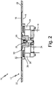
- FIG. 2 is a partial cross-sectional side view of flush static plate 10.
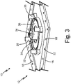
- FIG. 3 is a partial isometric view of an interior side of flush static plate 10 with housing 14 removed.
- FIGS. 2 and 3 will be discussed together.
- Flush static plate 10 includes faceplate 12, housing 14 (shown in FIG. 2 ), fixed resistance heater 24, self-regulating heater 26, and mounts 28.
- Faceplate 12 includes exterior surface 16, interior surface 18, ports 20, mounting holes 22, inner annular gap 30, and outer annular gap 32.
- Flush static plate 10 has the same structure and function as described with respect to FIG. 1 .
- Flush static plate 10 has faceplate 12 connected to housing 14.
- Faceplate 12 is made of thermally conductive material, such as aluminum or titanium. Faceplate 12 may be made of material having a thermal conductivity in the range of the thermal conductivity of titanium to the thermal conductivity of copper.
- Housing 14 is connected to a central portion of faceplate 12. Internal components of flush static plate 10 are located within housing 14.
- Faceplate 12 has exterior surface 16 at an outer surface of faceplate 12 and an interior surface 18 at an inner surface of faceplate 12.
- Housing 14 is connected to interior surface 18 of faceplate 12.
- Ports 20 are passages that extend through a central portion of faceplate 12 from exterior surface 16 to interior surface 18. Ports 20 are in alignment with housing 14.
- Mounting holes 22 extend through faceplate 12 from exterior surface 16 to interior surface 18. Mounting holes 22 are positioned near a periphery of faceplate 12.
- flush static plate 10 has fixed resistance heater 24 with a first end connected to and in thermal communication with interior surface 18 of faceplate 12 adjacent ports 20.
- Fixed resistance heater 24 surrounds a portion of faceplate 12. As such, fixed resistance heater surrounds interior portions of ports 20, which extend through faceplate 12 within fixed resistance heater 24.
- a second end of fixed resistance heater 24 is connected to housing 14.
- Fixed resistance heater 24 is a constant resistance heater.
- the first end of fixed resistance heater 24 is electrically connected to self-regulating heater 26.
- Self-regulating heater 26 is connected to and in thermal communication with interior surface 18 of faceplate 12.
- Self-regulating heater 26 is annular such that self-regulating heater 26 is spaced from and surrounds fixed resistance heater 24.
- Self-regulating heater 26 is a ceramic self-regulating heater, such as a positive temperature coefficient resistive heater. For example, self-regulating heater 26 automatically increases resistance to limit power output after reaching a certain temperature. Self-regulating heater 26 may also be a thermostatically-controlled heater or a heater self-regulated by any other suitable method.
- Mounts 28 are positioned between interior surface 18 of faceplate 12 and housing 14. Housing 14 is connected to interior surface 18 of faceplate 12 via mounts 28. Mounts 28 are adjacent a periphery of self-regulating heater 26.
- Mounts 28 are formed of a low thermal conductivity material. Mounts 28 may be formed of one or more of steel, titanium, plastic, composite, or any other suitable low thermal conductivity material.
- flush static plate 10 has four mounts 28. In alternate embodiments, flush static plate 10 may have any number of mounts 28.
- Faceplate 12 has inner annular gap 30, which is a space extending into faceplate 12 from interior surface 18 of faceplate 12 between fixed resistance heater 24 and self-regulating heater 26.
- faceplate 12 has a decreased thickness at inner annular gap 30.
- Inner annular gap 30 surrounds fixed resistance heater 24.
- Inner annular gap 30 extends into faceplate beyond fixed resistance heater 24 such that inner annular gap 30 is closer to exterior surface 16 of faceplate than fixed resistance heater 24.
- Inner annular gap 30 may have a uniform width.
- Outer annular gap 32 is a space that extends into faceplate 12 from interior surface 18 of faceplate 12 such that outer annular gap 32 surrounds self-regulating heater 26.
- faceplate 12 has a decreased thickness at outer annular gap 32, and self-regulating heater 26 is positioned between inner annular gap 30 and outer annular gap 32.
- Outer annular gap 22 may have a uniform width.
- Flush static plate 10 is installed on an aircraft and exposed to external airflow, which may contain water and/or ice particles.
- Fixed resistance heater 24 and self-regulating heater 26 provide heat to flush static plate 10 to prevent and remove ice accumulation.
- Fixed resistance heater 24 also removes moisture that enters ports 20 during flight or when grounded. Upon start-up, heat from fixed resistance heater 24 is provided to ports 20 to bake out (or burn off or boil out) water that is ingested when the aircraft is grounded (or in flight) that would otherwise remain in ports 20 and block the pressure path within flush static plate 10.
- self-regulating heater 26 As the temperature of self-regulating heater 26 increases, the resistance of self-regulating heater 26 increases after a certain temperature has been reached, or set-point temperature (as defined by the self-regulating design), which reduces the amount of power consumed by both self-regulating heater 26 and fixed resistance heater 24. As the temperature of self-regulating heater 26 decreases below the set-point temperature, the resistance of self-regulating heater 26 decreases, which increases the amount of power consumed by both self-regulating heater 26 and fixed resistance heater 24. Self-regulating heater 26 utilizes an automatic shut-off. When self-regulating heater 26 reaches a certain temperature, or certain set-point, self-regulating heater 26 increases its resistance to choke the power draw of self-regulating heater 26 and fixed resistance heater 24 of flush static plate 10. The set-point may be in a range of about 80 degrees Celsius to about 130 degrees Celsius.
- faceplate 12 is thermally conductive.
- Mounts 28, inner annular gap 30, and outer annular gap 32 keep heat at a center portion of aluminum faceplate 12.
- Mounts 28 are made of low thermal conductivity material to minimize heat loss through mounts 28.
- Inner annular gap 30 and outer annular gap 32 minimize heat loss to faceplate 12 via conduction.
- Inner annular gap 30 prevents heat from fixed resistance heater 24 from moving beyond inner annular gap 30, or keeps heat in the center of faceplate 12.
- Inner annular gap 30 extends closer to exterior surface 16 of faceplate than fixed resistance heater 24 to better prevent heat loss to faceplate 12.
- Outer annular gap 32 prevents heat from fixed resistance heater 24 and self-regulating heater 26 from moving beyond outer annular gap 32, or keeps heat in the center of faceplate 12.
- inner annular gap 30 and outer annular gap 32 are features that decrease heat transfer radially across inner annular gap 30 and outer annular gap 32, respectively, providing thermal separation for fixed resistance heater 24 and self-regulating heater 26.
- Inner annular gap 30 and outer annular gap 32 define decreased thickness of faceplate 12 to prevent heat loss beyond inner annular gap 30 and outer annular gap 32.
- Fixed resistance heater 24 and self-regulating heater 26 provide anti-icing and moisture management of flush static plate 10 to ensure flush static plate 10 functions properly.
- Self-regulating heater 26 is spaced from fixed resistance heater 24 so that self-regulating heater 26 effectively chokes the power draw at the desired temperature.
- Mounts 28, inner annular gap 30, and outer annular gap 32 keep heat at a center portion of aluminum faceplate 12, such as at ports 20, to minimize heat loss from fixed resistance heater 24 and self-regulating heater 26 to faceplate 12, housing 14, and other areas of flush static plate 10. Thus, heat is maintained only where required, resulting in more efficient use of power.
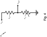
- FIG. 4 is a schematic view of circuitry 34 of flush static plate 10.
- Circuitry 34 includes input voltage V IN , resistor R 1 , resistor R 2 , and output voltage V OUT .
- R 1 is the resistor of fixed resistance heater 24.
- R 2 is the resistor of self-regulating heater 26. Resistor R 1 and resistor R 2 are connected in series. As such, fixed resistance heater 24 and self-regulating heater 26 are electrically connected in series. Circuitry 34 of flush static plate 10 does not include a switch between resistor R 1 of fixed resistance heater 24 and resistor R 2 of self-regulating heater 26.
- Fixed resistance heater 24 receives power via input voltage V IN provided to resistor R 1 as current. As such, current flows through resistor R 1 of fixed resistance heater 24 and then to resistor R 2 of self-regulating heater 26. Due to self-regulating heater 26, the combination of fixed resistance heater 24 and self-regulating heater 26 connected in series is also self-regulating. As such, circuitry 34 of flush static plate 10 is self-regulating. When flush static plate 10 increases in temperature, the total resistance of fixed resistance heater 24 and self-regulating heater 26 increases, decreasing the current, which decreases power consumption. When flush static plate 10 decreases in temperature, the total resistance of fixed resistance heater 24 and self-regulating heater 26 decreases to increase the current, which increases power and provides heat needed to maintain deicing and anti-icing capabilities in cold environments. Output voltage V OUT is a voltage that allows for monitoring of self-regulating heater 26 if desired.
- self-regulating heater 26 which utilizes the automatic shut-off, as described above with respect to FIGS. 2 and 3 , and chokes the power draw at a set-point temperature.
- self-regulating heater 26 utilizes the automatic shut-off, as described above with respect to FIGS. 2 and 3 , and chokes the power draw at a set-point temperature.
- the set-point temperature is generally not reached.
- the set-point temperature may be reached and exceeded to increase resistance and choke the power output.
- Fixed resistance heater 24 receives the most heat and draws the most power, upon power-up, allowing for bake out of ports 20, as discussed above with respect to FIGS. 2 and 3 .
- Fixed resistance heater 24 is more prone to rapid power-up due to its relatively small sized compared to self-regulating heater 26, which is larger and less prone to larger thermal shifts.
- self-regulating heater 26 heats up, the total resistance of fixed resistance heater 24 and self-regulating heater 26 increases to decrease the amount of power consumed. As such, no active control by software or other electromechanical means is necessary to regulate fixed resistance heater 24 and self-regulating heater 26.
- circuitry 34 passively controls the amount of power consumed by fixed resistance heater 24 and self-regulating heater 26, circuitry 34 does not include a switch, such as a mechanical or thermal switch, which would require additional circuitry and could result in increased development lead times and reduced reliability. Additionally, designs with active control may get too hot when the aircraft is grounded if the heaters are not turned off. Thus, flush static plate 10 is less complex, less prone to failure, more reliable, and has reduced associated lead time and technical risk.
- Self-regulating heater 26 connected in series with fixed resistance heater 24 prevents excessive power consumption and burn-out of fixed resistance heater 24 and self-regulating heater 26 via the automatic shut-off. Further, flush static plate 10 uses power more efficiently and is more cost-effective.
- FIG. 5 is a partial cross-sectional side view of flush static plate 10A including switch 36A.
- FIG. 6 is a schematic view of circuitry 34A of flush static plate 10A.
- Flush static plate 10A includes faceplate 12A, housing 14A, fixed resistance heater 24A, self-regulating heater 26A, switch 36A, and circuitry 34A.
- Circuitry 34A includes input voltage V INA , resistor R 1A , resistor R 1B , and resistor R 2A .
- Flush static plate 10A has generally the same structure and function as flush static plate 10 described with respect to FIGS. 1-4 .
- flush static plate 10A includes switch 36A.
- Switch 36A is positioned within housing 14A. In alternate embodiments, switch 36A may be positioned in any suitable housing or area of flush static plate 10A.
- Switch 36A may be a thermal switch, an electronically-controlled switch, or any other suitable switch.
- R 1A and R 1B are the resistors of fixed resistance heater 24A.
- R 2A is the resistor of self-regulating heater 26A.
- Switch 36A is between resistors R 1A and R 1B and between resistors R 1A and R 2A . As such, switch 36A is between fixed resistance heater 24A and self-regulating heater 26A.
- Resistors R 1A and R 1B are connected in series when switch 36A is in a first position. Switch 36A is in a first position when circuitry 34A is unpowered. When switch 36A is in a first position, all of the current, and thus heat, is directed to fixed resistance heater 24A. As such, fixed resistance heater 24A responds rapidly at start-up and effectively achieves bake out more quickly.
- Resistors R 1A and R 2A are connected in series when switch 36A is in a second position. When switch 36A is in a second position, current is divided between fixed resistance heater 24A and self-regulating heater 26A, and fixed resistance heater 24A and self-regulating heater 26A function the same as fixed resistance heater 24 and self-regulating heater 26 described with respect to FIGS. 2-4 .
- switch 36A may require active control of flush static plate 10A and introduce a decrease in reliability, switch 36A can offer some performance benefits, particularly at start-up. Additionally, when switch 36A is in the second position, flush static plate 10A can be passively controlled and achieve optimal de-icing and moisture management.
Landscapes
- Engineering & Computer Science (AREA)
- Aviation & Aerospace Engineering (AREA)
- Physics & Mathematics (AREA)
- General Physics & Mathematics (AREA)
- Surface Heating Bodies (AREA)
- Resistance Heating (AREA)
Claims (13)
- Bündige statische Platte (10) zum Messen eines Drucks an der äußeren Formlinie eines Luftfahrzeugs, wobei die bündige statische Platte Folgendes umfasst:eine Frontplatte (12), die einen Anschluss (20) beinhaltet, der sich von einer Außenfläche (16) der Frontplatte zu einer Innenfläche (18) der Stirnplatte erstreckt;eine feststehende Widerstandsheizung (24), die in thermischer Kommunikation mit der Innenfläche steht und den Anschluss umgibt;eine selbstregulierende Heizung (26), die in thermischer Kommunikation mit der Innenfläche steht und die feststehende Widerstandsheizung umgibt; undeinen äußeren ringförmigen Spalt (32), der die selbstregulierende Heizung umgibt und dazu konfiguriert ist, die Wärmeübertragung radial über das Merkmal zu verringern, wobei der äußere ringförmige Spalt (32) eine verringerte Dicke der Frontplatte an der Stelle definiert, an der der äußere ringförmige Spalt vorhanden ist;wobei die feststehende Widerstandsheizung und die selbstregulierende Heizung elektrisch in Reihe geschaltet sind.
- Bündige statische Platte nach Anspruch 1, wobei die statische Platte keinen Schalter zwischen der feststehenden Widerstandsheizung und der selbstregulierenden Heizung beinhaltet.
- Bündige statische Platte nach Anspruch 1 oder 2, wobei die Frontplatte aus einem Material besteht, das eine thermische Leitfähigkeit im Bereich zwischen der thermischen Leitfähigkeit von Titan und der thermischen Leitfähigkeit von Kupfer aufweist.
- Bündige statische Platte nach Anspruch 1, 2 oder 3, ferner umfassend ein Merkmal, das zwischen der feststehenden Widerstandsheizung und der selbstregulierenden Heizung positioniert ist, die dazu konfiguriert ist, die Wärmeübertragung radial über das Merkmal zu verringern.
- Bündige statische Platte nach Anspruch 4, wobei das Merkmal ein innerer ringförmiger Spalt (30) ist, der eine verringerte Dicke der Frontplatte an der Stelle definiert, an der der innere ringförmige Spalt vorhanden ist.
- Bündige statische Platte nach Anspruch 1, ferner umfassend:einen inneren ringförmigen Spalt (30), der sich von der Innenfläche der Frontplatte in diese hinein erstreckt;wobei sich der äußere ringförmige Spalt von der Innenfläche der Frontplatte in die Frontplatte hinein erstreckt; undwobei die selbstregulierende Heizung zwischen dem inneren ringförmigen Spalt und dem äußeren ringförmigen Spalt angeordnet ist.
- Bündige statische Platte nach einem vorstehenden Anspruch, ferner umfassend eine Halterung (28), die zwischen der Innenfläche der Frontplatte und einem Gehäuse der bündigen statischen Platte angeordnet ist, wobei die Halterung aus einem Material mit geringer thermischen Leitfähigkeit gebildet ist.
- Bündige statische Platte nach Anspruch 7, wobei die Halterung aus mindestens einem von Stahl, Titan, Verbundwerkstoff und Kunststoff gebildet ist.
- Bündige statische Platte nach Anspruch 7 oder 8, wobei die Halterung an die selbstregulierende Heizung angrenzt.
- Bündige statische Platte nach einem der vorstehenden Ansprüche, ferner umfassend eine Vielzahl von Halterungen (28) umfasst, die zwischen der Innenfläche der Frontplatte und einem Gehäuse positioniert ist, wobei die Vielzahl von Halterungen aus einem Material mit geringer thermischer Leitfähigkeit besteht und an das selbstregulierende Heizelement angrenzt.
- Bündige statische Platte nach einem vorstehenden Anspruch, wobei sich der Anschluss (20) durch einen Teil der Frontplatte innerhalb der feststehenden Widerstandsheizung erstreckt, sodass die feststehende Widerstandsheizung einen inneren Teil des Anschlusses umgibt.
- Bündige statische Platte nach Anspruch 1, ferner umfassend einen Schalter (36) zwischen der feststehenden Widerstandsheizung und der selbstregulierenden Heizung, und optional wobei es sich bei dem Schalter um einen thermischen Schalter oder einen elektronisch gesteuerten Schalter handelt.
- Verfahren zum Heizen einer statischen Platte (10), um einen Druck an der äußeren Formlinie eines Luftfahrzeugs zu messen, wobei das Verfahren Folgendes umfasst:Positionieren einer feststehenden Widerstandsheizung, die in thermischer Kommunikation mit einer Innenfläche einer Frontplatte der statischen Platte steht und einen Anschluss in der Frontplatte umgibt;Positionieren einer selbstregulierenden Heizung so, dass sie in thermischer Kommunikation mit der Innenfläche der Frontplatte steht und die feststehende Widerstandsheizung umgibt;Verringern einer Wärmeübertragung radial über einen äußeren ringförmigen Spalt, der die selbstregulierende Heizung umgibt, wobei der äußere ringförmige Spalt (32) eine verringerte Dicke der Frontplatte an einer Stelle definiert, an der der äußere ringförmige Spalt existiert; undBewirken, dass Strom durch die feststehende Widerstandsheizung und die selbstregulierende Heizung in Reihe fließt.
Applications Claiming Priority (1)
| Application Number | Priority Date | Filing Date | Title |
|---|---|---|---|
| US16/714,064 US11649057B2 (en) | 2019-12-13 | 2019-12-13 | Static plate heating arrangement |
Publications (2)
| Publication Number | Publication Date |
|---|---|
| EP3836749A1 EP3836749A1 (de) | 2021-06-16 |
| EP3836749B1 true EP3836749B1 (de) | 2022-08-03 |
Family
ID=73835494
Family Applications (1)
| Application Number | Title | Priority Date | Filing Date |
|---|---|---|---|
| EP20213883.0A Active EP3836749B1 (de) | 2019-12-13 | 2020-12-14 | Statische plattenheizanordnung |
Country Status (3)
| Country | Link |
|---|---|
| US (1) | US11649057B2 (de) |
| EP (1) | EP3836749B1 (de) |
| CA (1) | CA3101749A1 (de) |
Family Cites Families (82)
| Publication number | Priority date | Publication date | Assignee | Title |
|---|---|---|---|---|
| US3082622A (en) | 1956-09-27 | 1963-03-26 | North American Aviation Inc | Angle of attack and sideslip indicator |
| US3208277A (en) | 1960-10-14 | 1965-09-28 | Specialties Inc | Angle of attack indicating system |
| US3400582A (en) | 1967-05-08 | 1968-09-10 | Eric S. Warner | Boat speed indicator |
| DE1623526A1 (de) | 1967-11-22 | 1971-05-13 | Precitronic | Anstellwinkelgeber |
| US3514997A (en) | 1968-12-23 | 1970-06-02 | Teledyne Inc | Airstream direction detector |
| US3604259A (en) | 1969-05-02 | 1971-09-14 | Rosemount Eng Co Ltd | Angle of attack measuring device with adjustable airfoil |
| GB1272850A (en) | 1969-12-15 | 1972-05-03 | Ferranti Ltd | Improvements relating to airflow direction indicators |
| US3882721A (en) | 1973-11-16 | 1975-05-13 | Rosemount Inc | Vane type airflow sensor |
| US4230290A (en) | 1978-05-01 | 1980-10-28 | Townsend Engineering Company | Airplane angle of attack and direction of flight indicator |
| GB2039676A (en) | 1979-01-17 | 1980-08-13 | Ferranti Ltd | Flow direction indicators |
| US4468961A (en) | 1980-10-17 | 1984-09-04 | Berg Lauren V | Fluid direction meter suitable for angle of attack meter for aircraft |
| US4390950A (en) | 1980-11-28 | 1983-06-28 | Sundstrand Corporation | Angle of attack based pitch generator and head up display |
| US4458137A (en) | 1981-04-09 | 1984-07-03 | Rosemount Inc. | Electric heater arrangement for fluid flow stream sensors |
| DE3528135A1 (de) | 1985-08-06 | 1987-04-02 | Messerschmitt Boelkow Blohm | Einrichtung zur verringerung des reibungswiderstandes |
| US4830164A (en) | 1985-10-10 | 1989-05-16 | Hays Bill J | Heat puck for clutches and flywheels |
| FR2626375B1 (fr) | 1988-01-26 | 1990-06-08 | Thomson Csf | Capteur de direction de l'ecoulement de l'air, comportant un dispositif electromagnetique d'amortissement |
| JP3023170B2 (ja) | 1989-03-08 | 2000-03-21 | ローズマウント インコーポレイテッド | 空気データセンサーの水分離装置 |
| US5062869A (en) * | 1989-03-08 | 1991-11-05 | Rosemount Inc. | Water separator for air data sensor |
| US5025661A (en) | 1989-12-11 | 1991-06-25 | Allied-Signal Inc. | Combination air data probe |
| US5115237A (en) | 1990-04-16 | 1992-05-19 | Safe Flight Instrument Corporation | Combination aircraft yaw/angle of attack sensor |
| US5322246A (en) | 1991-08-12 | 1994-06-21 | Mcdonnell Douglas Corporation | Ice prevention device for airfoils |
| US5442958A (en) | 1992-12-15 | 1995-08-22 | The B.F. Goodrich Company | Deployable probe combined with flush static port |
| US5466067A (en) | 1993-09-17 | 1995-11-14 | The B. F. Goodrich Company | Multifunctional air data sensing probes |
| US5438865A (en) * | 1993-12-16 | 1995-08-08 | Safe Flight Instrument Corporation | Angle of attack sensor |
| JP2001505659A (ja) | 1996-10-16 | 2001-04-24 | ローズマウント・エアロスペース・インコーポレーテッド | 加熱式空気データプローブ |
| US6070475A (en) | 1997-10-15 | 2000-06-06 | Rosemont Aerospace Inc. | Air data probe with heater means within wall |
| RU2152042C1 (ru) | 1998-05-26 | 2000-06-27 | Центральный аэрогидродинамический институт им. проф. Н.Е. Жуковского | Приемник воздушного давления (варианты) |
| US6076963A (en) | 1998-10-20 | 2000-06-20 | Avionics Specialties, Inc. | Aircraft probe with integral air temperature sensor |
| FR2787886B1 (fr) | 1998-12-23 | 2001-03-16 | Sextant Avionique | Procede et dispositif de reglage d'une girouette et girouette reglable par ce procede |
| FR2787885B1 (fr) | 1998-12-23 | 2001-03-09 | Sextant Avionique | Girouette de mesure de l'orientation du vent a rechauffeur integre |
| US6510740B1 (en) | 1999-09-28 | 2003-01-28 | Rosemount Inc. | Thermal management in a pressure transmitter |
| FR2803387B1 (fr) | 1999-12-30 | 2002-03-15 | Thomson Csf Sextant | Dispositif de positionnement angulaire d'une sonde d'incidence sur une paroi, du type comportant une girouette mobile autour d'un axe, notamment sur une paroi d'aeronef |
| DE10124530B8 (de) | 2001-05-19 | 2006-01-12 | Eads Deutschland Gmbh | Sensorstruktur zur Strömungsdatenmessung an einem Strömungskörper |
| FR2829824B1 (fr) | 2001-09-14 | 2004-04-23 | Thales Sa | Dispositif d'etancheite d'une cavite, notamment pour sonde de mesure d'incidence utilisee en aeronautique |
| DE10146321B4 (de) | 2001-09-20 | 2008-08-14 | Robert Bosch Gmbh | Sensorbaustein mit einem Sensorelement, das von einem Heizelement umgeben ist |
| US6612166B2 (en) | 2001-12-13 | 2003-09-02 | Rosemount Aerospace Inc. | Variable viscosity damper for vane type angle of attack sensor |
| US6672152B2 (en) | 2001-12-21 | 2004-01-06 | Honeywell International Inc. | Flush surface air data sensor |
| US6772976B1 (en) | 2002-04-10 | 2004-08-10 | Honeywell International, Inc. | Sensor for measuring wind angle |
| US6941805B2 (en) | 2003-06-26 | 2005-09-13 | Rosemount Aerospace Inc. | Multi-function air data sensing probe having an angle of attack vane |
| EP1721172B1 (de) | 2003-12-04 | 2008-01-23 | Thales | Drehgelenk für eine multifunktionelle drucksonde mit drehflügel |
| US20080190174A1 (en) | 2005-05-10 | 2008-08-14 | Berend Jan Kooi | Sensor Module Package |
| EP1844863A1 (de) | 2006-04-12 | 2007-10-17 | General Electric Company | Artikel enthaltend eine Oberfläche mit niedriger Benetzbarkeit und dessen Herstellungsverfahren |
| US7597018B2 (en) | 2007-04-11 | 2009-10-06 | Rosemount Aerospace Inc. | Pneumatic line isolation and heating for air data probes |
| US20100116806A1 (en) | 2007-05-08 | 2010-05-13 | Honeywell International Inc. | Automated heating system for ports susceptible to icing |
| FR2916276B1 (fr) | 2007-05-14 | 2009-08-28 | Airbus France Sas | Dispositif et procede d'estimation d'un angle d'incidence d'un aeronef |
| DE102008007469A1 (de) | 2008-02-04 | 2009-08-06 | Airbus Deutschland Gmbh | Verlängerungsteil für eine Einlaufklappe, Einlaufklappe mit einem solchen Verlängerungsteil und Triebwerk mit einer Einlaufklappe |
| US7748268B2 (en) | 2008-07-13 | 2010-07-06 | Brooks Instrument, Llc | Thermal flow meter |
| US8037750B2 (en) | 2009-10-29 | 2011-10-18 | Rosemount Aerospace, Inc. | Impending icing probe with thermal isolation pedestal |
| CA2745138A1 (en) | 2010-07-02 | 2012-01-02 | Thales | Probe for measuring the total pressure of a flow and method for implementing the probe |
| US8397565B1 (en) | 2011-04-15 | 2013-03-19 | Florida Turbine Technologies, Inc. | High response air angle probe |
| US8776608B2 (en) | 2011-10-31 | 2014-07-15 | Rosemount Inc. | Coplanar process fluid pressure sensor module |
| WO2013177695A1 (en) | 2012-05-31 | 2013-12-05 | UNIVERSITé LAVAL | Method and apparatus for determining an icing condition status of an environment |
| CN103410682A (zh) | 2013-07-19 | 2013-11-27 | 曹二林 | 一种风向仪 |
| FR3011082B1 (fr) | 2013-09-20 | 2015-10-16 | Thales Sa | Sonde de mesure aerodynamique a evacuation de liquide d'infiltration par gravite |
| US20150122797A1 (en) | 2013-11-04 | 2015-05-07 | Eggers & Associates, Inc. | Isothermal Cooking Plate Apparatus, System, and Method of Manufacture and Use |
| US9884685B2 (en) * | 2014-05-28 | 2018-02-06 | The Boeing Company | External case heater for an angle of attack sensor |
| CN104034301B (zh) | 2014-06-10 | 2017-04-26 | 中国商用飞机有限责任公司 | 微小型迎角传感器 |
| US9702783B2 (en) | 2014-08-01 | 2017-07-11 | Rosemount Aerospace Inc. | Air data probe with fluid intrusion sensor |
| US20160114883A1 (en) | 2014-10-23 | 2016-04-28 | The Boeing Company | Actively-controlled superhydrophobic surfaces |
| DE202014105763U1 (de) | 2014-11-28 | 2016-01-07 | Argos Messtechnik Gmbh | Vorrichtung zur Analyse von Messgasen, inbesondere Atemluft |
| US20160238456A1 (en) | 2015-02-12 | 2016-08-18 | Rosemount Aerospace Inc. | Air temperature sensor and fabrication |
| GB2541356A (en) | 2015-06-08 | 2017-02-22 | Meggitt (Uk) Ltd | Moving-vane angle of attack probe |
| US10179654B2 (en) | 2015-10-20 | 2019-01-15 | Honeywell International Inc. | Architecture for air data probe power supply control |
| US10048288B2 (en) | 2016-01-08 | 2018-08-14 | Rosemount Aerospace Inc. | Angle of attack vane with differential pressure validation |
| FR3049153B1 (fr) * | 2016-03-21 | 2018-04-06 | Valeo Systemes D'essuyage | Circuit electrique chauffant et element chauffant pour balai d’essuie-glace, procede de realisation d’un element chauffant, et balai d’essuie-glace |
| US10457412B2 (en) | 2016-09-16 | 2019-10-29 | Rosemount Aerospace Inc. | Electrical isolation of angle of attack vane bearings |
| CN107843249A (zh) | 2016-09-21 | 2018-03-27 | 谢潇君 | 一种可除冰气流偏角传感器 |
| US10197588B2 (en) | 2016-11-09 | 2019-02-05 | Honeywell International Inc. | Thin film heating systems for air data probes |
| US10725065B2 (en) | 2016-11-14 | 2020-07-28 | Rosemount Aerospace Inc. | Angle of attack sensor with rotatable airfoil |
| CN106628206B (zh) | 2016-12-15 | 2019-01-15 | 武汉航空仪表有限责任公司 | 一种小转动力矩防雷结构 |
| US10422702B2 (en) | 2017-06-08 | 2019-09-24 | Rosemount Aerospace Inc. | Total air temperature probe with reduced icing sensor flow passage geometry |
| CN107687350A (zh) | 2017-08-14 | 2018-02-13 | 大连理工大学 | 一种双层吸液芯无开孔高效冷却涡轮导叶装置 |
| US10730637B2 (en) | 2017-09-29 | 2020-08-04 | Rosemount Aerospace Inc. | Integral vane base angle of attack sensor |
| US10393766B2 (en) | 2017-08-17 | 2019-08-27 | Rosemount Aerospace Inc. | Water management system for angle of attack sensors |
| US11181545B2 (en) * | 2017-08-17 | 2021-11-23 | Rosemount Aerospace Inc. | Angle of attack sensor with thermal enhancement |
| SE541696C2 (en) | 2017-10-09 | 2019-11-26 | Mobile Climate Control Sverige Ab | Selfregulating heater |
| EP4001119B1 (de) | 2018-01-05 | 2024-06-05 | Rosemount Aerospace Inc. | Merkmale zur vermeidung von eisansammlungen auf beheizten frontplatten |
| EP3749577B1 (de) | 2018-02-07 | 2023-04-05 | Aerosonic LLC | Flugzeugluftstromsensorsonde und verfahren zur implementierung einer flugzeugsensorsonde |
| US11105691B2 (en) | 2018-03-30 | 2021-08-31 | Honeywell International Inc. | Self-regulating heating system for a total air temperature probe |
| US10928416B2 (en) | 2018-05-09 | 2021-02-23 | Rosemount Aerospace Inc. | Dual heated ramp for ice and water management in angle of attack sensors |
| US10877062B2 (en) | 2018-05-09 | 2020-12-29 | Rosemount Aerospace Inc. | Aft-located heated ramp for ice and water management of angle of attack sensors |
| US11486785B2 (en) * | 2019-03-28 | 2022-11-01 | Rosemount Aerospace Inc. | Thermal management system for air data sensor module |
-
2019
- 2019-12-13 US US16/714,064 patent/US11649057B2/en active Active
-
2020
- 2020-12-04 CA CA3101749A patent/CA3101749A1/en active Pending
- 2020-12-14 EP EP20213883.0A patent/EP3836749B1/de active Active
Also Published As
| Publication number | Publication date |
|---|---|
| US11649057B2 (en) | 2023-05-16 |
| EP3836749A1 (de) | 2021-06-16 |
| CA3101749A1 (en) | 2021-06-13 |
| BR102020025408A2 (pt) | 2021-06-29 |
| US20210179277A1 (en) | 2021-06-17 |
Similar Documents
| Publication | Publication Date | Title |
|---|---|---|
| US11414196B2 (en) | Ice protection system and controller | |
| RU2501717C2 (ru) | Способ управления электрической противообледенительной системой | |
| EP2863195B1 (de) | Gesamtlufttemperatursensoren | |
| US9970824B2 (en) | Sensor probe with anti-icing | |
| EP2163475B1 (de) | Propellerenteisungssystem | |
| US8937807B2 (en) | Circuit board heatsink and heatframe structures with heater element for circuit board operation at below zero temperature | |
| EP4235189B1 (de) | Generativ gefertigte heizer für luftdatensonden | |
| US7938368B2 (en) | Nosecone ice protection system for a gas turbine engine | |
| US20110036950A1 (en) | De-icing and/or anti-icing system for the leading edge of an aircraft wing | |
| US20100288244A1 (en) | Method for controlling thermal effluents generated by an aircraft and cooling device for an aircraft implementing said method | |
| US20060196994A1 (en) | Hybrid electrical ice protection system and method including an energy saving mode | |
| WO2010128299A1 (en) | Heating system | |
| ATE348321T1 (de) | Fühler für luftfahrzeuge mit einem integrierten lufttemperatursensor | |
| CN101411243B (zh) | 用于雷达屏蔽器的除冰系统 | |
| CN106585998A (zh) | 用于空气数据探针电源控制的架构 | |
| US11649057B2 (en) | Static plate heating arrangement | |
| EP2383186A2 (de) | Verfahren zur Kalibrierung eines Heizungssystems | |
| US8727607B2 (en) | Method of calibrating a heater system | |
| CN101505026A (zh) | 对接连接器 | |
| CN109552644A (zh) | 一种网状等离子体热刀 | |
| CN116198729A (zh) | 可调节防冰系统分隔条带 | |
| BR102020025408B1 (pt) | Placa estática nivelada e método de aquecimento de uma placa estática nivelada | |
| US9976481B2 (en) | Dual pressure deicing system | |
| KR20190116381A (ko) | 다층 세라믹을 위한 집적 온도 제어 및 방법 | |
| KR102051098B1 (ko) | Fads의 방빙을 위한 능동히터 장치 |
Legal Events
| Date | Code | Title | Description |
|---|---|---|---|
| PUAI | Public reference made under article 153(3) epc to a published international application that has entered the european phase |
Free format text: ORIGINAL CODE: 0009012 |
|
| STAA | Information on the status of an ep patent application or granted ep patent |
Free format text: STATUS: THE APPLICATION HAS BEEN PUBLISHED |
|
| AK | Designated contracting states |
Kind code of ref document: A1 Designated state(s): AL AT BE BG CH CY CZ DE DK EE ES FI FR GB GR HR HU IE IS IT LI LT LU LV MC MK MT NL NO PL PT RO RS SE SI SK SM TR |
|
| STAA | Information on the status of an ep patent application or granted ep patent |
Free format text: STATUS: REQUEST FOR EXAMINATION WAS MADE |
|
| 17P | Request for examination filed |
Effective date: 20211216 |
|
| RBV | Designated contracting states (corrected) |
Designated state(s): AL AT BE BG CH CY CZ DE DK EE ES FI FR GB GR HR HU IE IS IT LI LT LU LV MC MK MT NL NO PL PT RO RS SE SI SK SM TR |
|
| GRAP | Despatch of communication of intention to grant a patent |
Free format text: ORIGINAL CODE: EPIDOSNIGR1 |
|
| STAA | Information on the status of an ep patent application or granted ep patent |
Free format text: STATUS: GRANT OF PATENT IS INTENDED |
|
| INTG | Intention to grant announced |
Effective date: 20220218 |
|
| GRAS | Grant fee paid |
Free format text: ORIGINAL CODE: EPIDOSNIGR3 |
|
| GRAA | (expected) grant |
Free format text: ORIGINAL CODE: 0009210 |
|
| STAA | Information on the status of an ep patent application or granted ep patent |
Free format text: STATUS: THE PATENT HAS BEEN GRANTED |
|
| AK | Designated contracting states |
Kind code of ref document: B1 Designated state(s): AL AT BE BG CH CY CZ DE DK EE ES FI FR GB GR HR HU IE IS IT LI LT LU LV MC MK MT NL NO PL PT RO RS SE SI SK SM TR |
|
| REG | Reference to a national code |
Ref country code: AT Ref legal event code: REF Ref document number: 1509792 Country of ref document: AT Kind code of ref document: T Effective date: 20220815 Ref country code: CH Ref legal event code: EP |
|
| REG | Reference to a national code |
Ref country code: DE Ref legal event code: R096 Ref document number: 602020004338 Country of ref document: DE |
|
| REG | Reference to a national code |
Ref country code: IE Ref legal event code: FG4D |
|
| REG | Reference to a national code |
Ref country code: LT Ref legal event code: MG9D |
|
| REG | Reference to a national code |
Ref country code: NL Ref legal event code: MP Effective date: 20220803 |
|
| PG25 | Lapsed in a contracting state [announced via postgrant information from national office to epo] |
Ref country code: SE Free format text: LAPSE BECAUSE OF FAILURE TO SUBMIT A TRANSLATION OF THE DESCRIPTION OR TO PAY THE FEE WITHIN THE PRESCRIBED TIME-LIMIT Effective date: 20220803 Ref country code: RS Free format text: LAPSE BECAUSE OF FAILURE TO SUBMIT A TRANSLATION OF THE DESCRIPTION OR TO PAY THE FEE WITHIN THE PRESCRIBED TIME-LIMIT Effective date: 20220803 Ref country code: PT Free format text: LAPSE BECAUSE OF FAILURE TO SUBMIT A TRANSLATION OF THE DESCRIPTION OR TO PAY THE FEE WITHIN THE PRESCRIBED TIME-LIMIT Effective date: 20221205 Ref country code: NO Free format text: LAPSE BECAUSE OF FAILURE TO SUBMIT A TRANSLATION OF THE DESCRIPTION OR TO PAY THE FEE WITHIN THE PRESCRIBED TIME-LIMIT Effective date: 20221103 Ref country code: NL Free format text: LAPSE BECAUSE OF FAILURE TO SUBMIT A TRANSLATION OF THE DESCRIPTION OR TO PAY THE FEE WITHIN THE PRESCRIBED TIME-LIMIT Effective date: 20220803 Ref country code: LV Free format text: LAPSE BECAUSE OF FAILURE TO SUBMIT A TRANSLATION OF THE DESCRIPTION OR TO PAY THE FEE WITHIN THE PRESCRIBED TIME-LIMIT Effective date: 20220803 Ref country code: LT Free format text: LAPSE BECAUSE OF FAILURE TO SUBMIT A TRANSLATION OF THE DESCRIPTION OR TO PAY THE FEE WITHIN THE PRESCRIBED TIME-LIMIT Effective date: 20220803 Ref country code: FI Free format text: LAPSE BECAUSE OF FAILURE TO SUBMIT A TRANSLATION OF THE DESCRIPTION OR TO PAY THE FEE WITHIN THE PRESCRIBED TIME-LIMIT Effective date: 20220803 Ref country code: ES Free format text: LAPSE BECAUSE OF FAILURE TO SUBMIT A TRANSLATION OF THE DESCRIPTION OR TO PAY THE FEE WITHIN THE PRESCRIBED TIME-LIMIT Effective date: 20220803 |
|
| REG | Reference to a national code |
Ref country code: AT Ref legal event code: MK05 Ref document number: 1509792 Country of ref document: AT Kind code of ref document: T Effective date: 20220803 |
|
| PG25 | Lapsed in a contracting state [announced via postgrant information from national office to epo] |
Ref country code: PL Free format text: LAPSE BECAUSE OF FAILURE TO SUBMIT A TRANSLATION OF THE DESCRIPTION OR TO PAY THE FEE WITHIN THE PRESCRIBED TIME-LIMIT Effective date: 20220803 Ref country code: IS Free format text: LAPSE BECAUSE OF FAILURE TO SUBMIT A TRANSLATION OF THE DESCRIPTION OR TO PAY THE FEE WITHIN THE PRESCRIBED TIME-LIMIT Effective date: 20221203 Ref country code: HR Free format text: LAPSE BECAUSE OF FAILURE TO SUBMIT A TRANSLATION OF THE DESCRIPTION OR TO PAY THE FEE WITHIN THE PRESCRIBED TIME-LIMIT Effective date: 20220803 Ref country code: GR Free format text: LAPSE BECAUSE OF FAILURE TO SUBMIT A TRANSLATION OF THE DESCRIPTION OR TO PAY THE FEE WITHIN THE PRESCRIBED TIME-LIMIT Effective date: 20221104 |
|
| PG25 | Lapsed in a contracting state [announced via postgrant information from national office to epo] |
Ref country code: SM Free format text: LAPSE BECAUSE OF FAILURE TO SUBMIT A TRANSLATION OF THE DESCRIPTION OR TO PAY THE FEE WITHIN THE PRESCRIBED TIME-LIMIT Effective date: 20220803 Ref country code: RO Free format text: LAPSE BECAUSE OF FAILURE TO SUBMIT A TRANSLATION OF THE DESCRIPTION OR TO PAY THE FEE WITHIN THE PRESCRIBED TIME-LIMIT Effective date: 20220803 Ref country code: DK Free format text: LAPSE BECAUSE OF FAILURE TO SUBMIT A TRANSLATION OF THE DESCRIPTION OR TO PAY THE FEE WITHIN THE PRESCRIBED TIME-LIMIT Effective date: 20220803 Ref country code: CZ Free format text: LAPSE BECAUSE OF FAILURE TO SUBMIT A TRANSLATION OF THE DESCRIPTION OR TO PAY THE FEE WITHIN THE PRESCRIBED TIME-LIMIT Effective date: 20220803 Ref country code: AT Free format text: LAPSE BECAUSE OF FAILURE TO SUBMIT A TRANSLATION OF THE DESCRIPTION OR TO PAY THE FEE WITHIN THE PRESCRIBED TIME-LIMIT Effective date: 20220803 |
|
| REG | Reference to a national code |
Ref country code: DE Ref legal event code: R097 Ref document number: 602020004338 Country of ref document: DE |
|
| PG25 | Lapsed in a contracting state [announced via postgrant information from national office to epo] |
Ref country code: SK Free format text: LAPSE BECAUSE OF FAILURE TO SUBMIT A TRANSLATION OF THE DESCRIPTION OR TO PAY THE FEE WITHIN THE PRESCRIBED TIME-LIMIT Effective date: 20220803 Ref country code: EE Free format text: LAPSE BECAUSE OF FAILURE TO SUBMIT A TRANSLATION OF THE DESCRIPTION OR TO PAY THE FEE WITHIN THE PRESCRIBED TIME-LIMIT Effective date: 20220803 |
|
| PLBE | No opposition filed within time limit |
Free format text: ORIGINAL CODE: 0009261 |
|
| STAA | Information on the status of an ep patent application or granted ep patent |
Free format text: STATUS: NO OPPOSITION FILED WITHIN TIME LIMIT |
|
| PG25 | Lapsed in a contracting state [announced via postgrant information from national office to epo] |
Ref country code: AL Free format text: LAPSE BECAUSE OF FAILURE TO SUBMIT A TRANSLATION OF THE DESCRIPTION OR TO PAY THE FEE WITHIN THE PRESCRIBED TIME-LIMIT Effective date: 20220803 |
|
| 26N | No opposition filed |
Effective date: 20230504 |
|
| REG | Reference to a national code |
Ref country code: BE Ref legal event code: MM Effective date: 20221231 |
|
| PG25 | Lapsed in a contracting state [announced via postgrant information from national office to epo] |
Ref country code: SI Free format text: LAPSE BECAUSE OF FAILURE TO SUBMIT A TRANSLATION OF THE DESCRIPTION OR TO PAY THE FEE WITHIN THE PRESCRIBED TIME-LIMIT Effective date: 20220803 Ref country code: LU Free format text: LAPSE BECAUSE OF NON-PAYMENT OF DUE FEES Effective date: 20221214 |
|
| PG25 | Lapsed in a contracting state [announced via postgrant information from national office to epo] |
Ref country code: IE Free format text: LAPSE BECAUSE OF NON-PAYMENT OF DUE FEES Effective date: 20221214 |
|
| PG25 | Lapsed in a contracting state [announced via postgrant information from national office to epo] |
Ref country code: BE Free format text: LAPSE BECAUSE OF NON-PAYMENT OF DUE FEES Effective date: 20221231 |
|
| PG25 | Lapsed in a contracting state [announced via postgrant information from national office to epo] |
Ref country code: CY Free format text: LAPSE BECAUSE OF FAILURE TO SUBMIT A TRANSLATION OF THE DESCRIPTION OR TO PAY THE FEE WITHIN THE PRESCRIBED TIME-LIMIT Effective date: 20220803 |
|
| PG25 | Lapsed in a contracting state [announced via postgrant information from national office to epo] |
Ref country code: MK Free format text: LAPSE BECAUSE OF FAILURE TO SUBMIT A TRANSLATION OF THE DESCRIPTION OR TO PAY THE FEE WITHIN THE PRESCRIBED TIME-LIMIT Effective date: 20220803 Ref country code: IT Free format text: LAPSE BECAUSE OF FAILURE TO SUBMIT A TRANSLATION OF THE DESCRIPTION OR TO PAY THE FEE WITHIN THE PRESCRIBED TIME-LIMIT Effective date: 20220803 |
|
| PG25 | Lapsed in a contracting state [announced via postgrant information from national office to epo] |
Ref country code: MC Free format text: LAPSE BECAUSE OF FAILURE TO SUBMIT A TRANSLATION OF THE DESCRIPTION OR TO PAY THE FEE WITHIN THE PRESCRIBED TIME-LIMIT Effective date: 20220803 |
|
| PG25 | Lapsed in a contracting state [announced via postgrant information from national office to epo] |
Ref country code: MC Free format text: LAPSE BECAUSE OF FAILURE TO SUBMIT A TRANSLATION OF THE DESCRIPTION OR TO PAY THE FEE WITHIN THE PRESCRIBED TIME-LIMIT Effective date: 20220803 |
|
| PG25 | Lapsed in a contracting state [announced via postgrant information from national office to epo] |
Ref country code: BG Free format text: LAPSE BECAUSE OF FAILURE TO SUBMIT A TRANSLATION OF THE DESCRIPTION OR TO PAY THE FEE WITHIN THE PRESCRIBED TIME-LIMIT Effective date: 20220803 |
|
| REG | Reference to a national code |
Ref country code: CH Ref legal event code: PL |
|
| PG25 | Lapsed in a contracting state [announced via postgrant information from national office to epo] |
Ref country code: MT Free format text: LAPSE BECAUSE OF FAILURE TO SUBMIT A TRANSLATION OF THE DESCRIPTION OR TO PAY THE FEE WITHIN THE PRESCRIBED TIME-LIMIT Effective date: 20220803 |
|
| PG25 | Lapsed in a contracting state [announced via postgrant information from national office to epo] |
Ref country code: CH Free format text: LAPSE BECAUSE OF NON-PAYMENT OF DUE FEES Effective date: 20231231 |
|
| PG25 | Lapsed in a contracting state [announced via postgrant information from national office to epo] |
Ref country code: CH Free format text: LAPSE BECAUSE OF NON-PAYMENT OF DUE FEES Effective date: 20231231 |
|
| PG25 | Lapsed in a contracting state [announced via postgrant information from national office to epo] |
Ref country code: HU Free format text: LAPSE BECAUSE OF FAILURE TO SUBMIT A TRANSLATION OF THE DESCRIPTION OR TO PAY THE FEE WITHIN THE PRESCRIBED TIME-LIMIT; INVALID AB INITIO Effective date: 20201214 |
|
| PG25 | Lapsed in a contracting state [announced via postgrant information from national office to epo] |
Ref country code: TR Free format text: LAPSE BECAUSE OF FAILURE TO SUBMIT A TRANSLATION OF THE DESCRIPTION OR TO PAY THE FEE WITHIN THE PRESCRIBED TIME-LIMIT Effective date: 20220803 |
|
| PGFP | Annual fee paid to national office [announced via postgrant information from national office to epo] |
Ref country code: DE Payment date: 20251126 Year of fee payment: 6 |
|
| PGFP | Annual fee paid to national office [announced via postgrant information from national office to epo] |
Ref country code: GB Payment date: 20251120 Year of fee payment: 6 |
|
| PGFP | Annual fee paid to national office [announced via postgrant information from national office to epo] |
Ref country code: FR Payment date: 20251119 Year of fee payment: 6 |
|
| P01 | Opt-out of the competence of the unified patent court (upc) registered |
Free format text: CASE NUMBER: UPC_APP_0018616_3836749/2025 Effective date: 20251221 |