EP3835531A1 - Türantrieb mit einer leistungsstarken, kleinbauenden motoreinheit - Google Patents
Türantrieb mit einer leistungsstarken, kleinbauenden motoreinheit Download PDFInfo
- Publication number
- EP3835531A1 EP3835531A1 EP19214435.0A EP19214435A EP3835531A1 EP 3835531 A1 EP3835531 A1 EP 3835531A1 EP 19214435 A EP19214435 A EP 19214435A EP 3835531 A1 EP3835531 A1 EP 3835531A1
- Authority
- EP
- European Patent Office
- Prior art keywords
- door drive
- permanent magnets
- rotor
- output shaft
- carrier body
- Prior art date
- Legal status (The legal status is an assumption and is not a legal conclusion. Google has not performed a legal analysis and makes no representation as to the accuracy of the status listed.)
- Granted
Links
Images


Classifications
-
- H—ELECTRICITY
- H02—GENERATION; CONVERSION OR DISTRIBUTION OF ELECTRIC POWER
- H02K—DYNAMO-ELECTRIC MACHINES
- H02K1/00—Details of the magnetic circuit
- H02K1/06—Details of the magnetic circuit characterised by the shape, form or construction
- H02K1/22—Rotating parts of the magnetic circuit
- H02K1/27—Rotor cores with permanent magnets
- H02K1/2706—Inner rotors
- H02K1/272—Inner rotors the magnetisation axis of the magnets being perpendicular to the rotor axis
- H02K1/274—Inner rotors the magnetisation axis of the magnets being perpendicular to the rotor axis the rotor consisting of two or more circumferentially positioned magnets
- H02K1/2753—Inner rotors the magnetisation axis of the magnets being perpendicular to the rotor axis the rotor consisting of two or more circumferentially positioned magnets the rotor consisting of magnets or groups of magnets arranged with alternating polarity
- H02K1/278—Surface mounted magnets; Inset magnets
-
- E—FIXED CONSTRUCTIONS
- E05—LOCKS; KEYS; WINDOW OR DOOR FITTINGS; SAFES
- E05F—DEVICES FOR MOVING WINGS INTO OPEN OR CLOSED POSITION; CHECKS FOR WINGS; WING FITTINGS NOT OTHERWISE PROVIDED FOR, CONCERNED WITH THE FUNCTIONING OF THE WING
- E05F15/00—Power-operated mechanisms for wings
- E05F15/60—Power-operated mechanisms for wings using electrical actuators
- E05F15/603—Power-operated mechanisms for wings using electrical actuators using rotary electromotors
-
- E—FIXED CONSTRUCTIONS
- E05—LOCKS; KEYS; WINDOW OR DOOR FITTINGS; SAFES
- E05F—DEVICES FOR MOVING WINGS INTO OPEN OR CLOSED POSITION; CHECKS FOR WINGS; WING FITTINGS NOT OTHERWISE PROVIDED FOR, CONCERNED WITH THE FUNCTIONING OF THE WING
- E05F15/00—Power-operated mechanisms for wings
- E05F15/60—Power-operated mechanisms for wings using electrical actuators
- E05F15/603—Power-operated mechanisms for wings using electrical actuators using rotary electromotors
- E05F15/632—Power-operated mechanisms for wings using electrical actuators using rotary electromotors for horizontally-sliding wings
- E05F15/643—Power-operated mechanisms for wings using electrical actuators using rotary electromotors for horizontally-sliding wings operated by flexible elongated pulling elements, e.g. belts, chains or cables
-
- H—ELECTRICITY
- H02—GENERATION; CONVERSION OR DISTRIBUTION OF ELECTRIC POWER
- H02K—DYNAMO-ELECTRIC MACHINES
- H02K15/00—Processes or apparatus specially adapted for manufacturing, assembling, maintaining or repairing of dynamo-electric machines
- H02K15/02—Processes or apparatus specially adapted for manufacturing, assembling, maintaining or repairing of dynamo-electric machines of stator or rotor bodies
- H02K15/03—Processes or apparatus specially adapted for manufacturing, assembling, maintaining or repairing of dynamo-electric machines of stator or rotor bodies having permanent magnets
-
- E—FIXED CONSTRUCTIONS
- E05—LOCKS; KEYS; WINDOW OR DOOR FITTINGS; SAFES
- E05F—DEVICES FOR MOVING WINGS INTO OPEN OR CLOSED POSITION; CHECKS FOR WINGS; WING FITTINGS NOT OTHERWISE PROVIDED FOR, CONCERNED WITH THE FUNCTIONING OF THE WING
- E05F15/00—Power-operated mechanisms for wings
- E05F15/60—Power-operated mechanisms for wings using electrical actuators
- E05F15/603—Power-operated mechanisms for wings using electrical actuators using rotary electromotors
- E05F15/632—Power-operated mechanisms for wings using electrical actuators using rotary electromotors for horizontally-sliding wings
-
- E—FIXED CONSTRUCTIONS
- E05—LOCKS; KEYS; WINDOW OR DOOR FITTINGS; SAFES
- E05Y—INDEXING SCHEME ASSOCIATED WITH SUBCLASSES E05D AND E05F, RELATING TO CONSTRUCTION ELEMENTS, ELECTRIC CONTROL, POWER SUPPLY, POWER SIGNAL OR TRANSMISSION, USER INTERFACES, MOUNTING OR COUPLING, DETAILS, ACCESSORIES, AUXILIARY OPERATIONS NOT OTHERWISE PROVIDED FOR, APPLICATION THEREOF
- E05Y2201/00—Constructional elements; Accessories therefor
- E05Y2201/40—Motors; Magnets; Springs; Weights; Accessories therefor
- E05Y2201/43—Motors
- E05Y2201/434—Electromotors; Details thereof
-
- E—FIXED CONSTRUCTIONS
- E05—LOCKS; KEYS; WINDOW OR DOOR FITTINGS; SAFES
- E05Y—INDEXING SCHEME ASSOCIATED WITH SUBCLASSES E05D AND E05F, RELATING TO CONSTRUCTION ELEMENTS, ELECTRIC CONTROL, POWER SUPPLY, POWER SIGNAL OR TRANSMISSION, USER INTERFACES, MOUNTING OR COUPLING, DETAILS, ACCESSORIES, AUXILIARY OPERATIONS NOT OTHERWISE PROVIDED FOR, APPLICATION THEREOF
- E05Y2201/00—Constructional elements; Accessories therefor
- E05Y2201/40—Motors; Magnets; Springs; Weights; Accessories therefor
- E05Y2201/43—Motors
- E05Y2201/434—Electromotors; Details thereof
- E05Y2201/438—Rotors
-
- E—FIXED CONSTRUCTIONS
- E05—LOCKS; KEYS; WINDOW OR DOOR FITTINGS; SAFES
- E05Y—INDEXING SCHEME ASSOCIATED WITH SUBCLASSES E05D AND E05F, RELATING TO CONSTRUCTION ELEMENTS, ELECTRIC CONTROL, POWER SUPPLY, POWER SIGNAL OR TRANSMISSION, USER INTERFACES, MOUNTING OR COUPLING, DETAILS, ACCESSORIES, AUXILIARY OPERATIONS NOT OTHERWISE PROVIDED FOR, APPLICATION THEREOF
- E05Y2201/00—Constructional elements; Accessories therefor
- E05Y2201/40—Motors; Magnets; Springs; Weights; Accessories therefor
- E05Y2201/46—Magnets
-
- E—FIXED CONSTRUCTIONS
- E05—LOCKS; KEYS; WINDOW OR DOOR FITTINGS; SAFES
- E05Y—INDEXING SCHEME ASSOCIATED WITH SUBCLASSES E05D AND E05F, RELATING TO CONSTRUCTION ELEMENTS, ELECTRIC CONTROL, POWER SUPPLY, POWER SIGNAL OR TRANSMISSION, USER INTERFACES, MOUNTING OR COUPLING, DETAILS, ACCESSORIES, AUXILIARY OPERATIONS NOT OTHERWISE PROVIDED FOR, APPLICATION THEREOF
- E05Y2600/00—Mounting or coupling arrangements for elements provided for in this subclass
- E05Y2600/50—Mounting methods; Positioning
- E05Y2600/52—Toolless
- E05Y2600/526—Gluing or cementing
-
- E—FIXED CONSTRUCTIONS
- E05—LOCKS; KEYS; WINDOW OR DOOR FITTINGS; SAFES
- E05Y—INDEXING SCHEME ASSOCIATED WITH SUBCLASSES E05D AND E05F, RELATING TO CONSTRUCTION ELEMENTS, ELECTRIC CONTROL, POWER SUPPLY, POWER SIGNAL OR TRANSMISSION, USER INTERFACES, MOUNTING OR COUPLING, DETAILS, ACCESSORIES, AUXILIARY OPERATIONS NOT OTHERWISE PROVIDED FOR, APPLICATION THEREOF
- E05Y2900/00—Application of doors, windows, wings or fittings thereof
- E05Y2900/10—Application of doors, windows, wings or fittings thereof for buildings or parts thereof
- E05Y2900/13—Type of wing
- E05Y2900/132—Doors
Definitions
- the invention relates to a door drive for arrangement on or in connection with a door system, with which at least one wing element of the door system can be moved, having a motor unit with a housing in which a stator is accommodated and a rotor is rotatably arranged in the housing, the having an output shaft, wherein the output shaft can be brought into operative connection in a driving manner with the wing element. Furthermore, the invention relates to a door system with such a door drive, having at least one wing element, with which the door drive is operatively connected in a driving manner.
- a door drive for arrangement on a door system is known, and the drive is used to move wing elements of the door system, which is designed as an automatic sliding door.
- the door drive has a motor unit with a housing, and a gear unit, which is designed as a worm gear, is attached to the housing of the motor unit.
- the motor unit is thus designed as a high-speed motor, and with the gear unit the higher speed of the rotor of the motor unit is reduced to a lower speed for driving a belt pulley which is placed on an output shaft of the gear unit.
- a toothed belt is guided over the pulley and is connected to the wing elements of the automatic sliding door. Since the motor unit is designed to rotate quickly and the speed has to be reduced to the pulley, the gear unit is in connection with the motor necessary, which requires additional installation space, and which makes the construction of the door drive more complex.
- the spatial dimensioning of the door drive must be adapted to the necessity of the gear unit, and since the motor has a cylindrical basic shape, it takes up an installation space that does not allow optimal use of space in relation to its installation environment. The same applies to a worm gear, which runs transversely, especially in connection with the motor, and is therefore very space-intensive.
- the motor design must be short, especially in the direction in which the output shaft extends, otherwise installation space problems will arise when installing the motor unit.
- the runner in the carrier profile which is driven by a toothed belt via the pulley and which is used to accommodate a wing element, for example an automatic sliding door, must still be able to run past the pulley within the carrier profile.
- the motor unit should therefore be as short as possible in the direction in which the rotor axis extends.
- the cuboid body thus forms a housing as a carrier for the individual components of the door drive and is designed in one piece and, so to speak, monolithically over the entire dimension of the drive.
- the rotor is mounted by means of a standing axis enclosed in the cuboid body of the door drive, This results in an unfavorable load case due to the axis enclosed on one side, especially if high forces are introduced into the rotor via the gear stage in large, heavy all-glass wing elements, which must be absorbed via the opposite, vertical axis.
- Door drives are usually arranged above the linearly movable wing elements of an automatic sliding door system and have a carrier profile that forms a base body of the door system and the door drive is installed integrated in the carrier profile and the wing elements are likewise linearly guided.
- a toothed belt is generally used as the connecting means between the door drive and the wing elements, although other traction means such as chain connections and the like are also possible.
- the door drive forms its own structural unit with at least the motor, a power supply unit and a controller, which is integrated into the door system with the arrangement on the support profile.
- the door drive In order to make the carrier profile as small as possible with a corresponding panel, a housing or other structural parts, it is advantageous to make the door drive itself as compact as possible and with small dimensions.
- the door drive since wing elements made of glass can achieve large masses, the door drive must have a high power density in order to accelerate and decelerate such wing elements correspondingly strongly despite their small dimensions so that the door system still achieves the required dynamics even with large leaf elements.
- motor units in connection with a toothed belt are suitable as direct drives, in which the belt pulley is attached directly to the output shaft of the motor unit, over which the toothed belt is placed, which in turn is directly connected to the wing elements .
- the door drive can be operated with a minimum of noise, since no high motor speeds can be achieved, and with an appropriate design of the motor unit, power densities can be provided that are sufficient to accelerate leaf elements of, for example, 200kg to 250kg sufficiently for the operation of an automatic sliding door and also again to delay.
- the stator has a number of coils which, in the case of an internal rotor, are applied to teeth of the stator pointing radially inward.
- the rotor is rotatably mounted within the teeth pointing radially inwards and it comprises a number of permanent magnets. If the coils are electrically controlled and energized in a radial direction, the rotor is replaced with the permanent magnets in rotation.
- the connection of the permanent magnets to a support body of the rotor is often problematic. As a rule, the permanent magnets are attached to the clamp elements Carrier body fixed or cast with a potting compound together with the carrier body.
- the object of the invention is to create a door drive with a motor unit which has a high integration density and a high power density, and wherein the motor in connection with the at least one wing element is to be designed, in particular, as a direct drive.
- a compact design of the motor unit is to be achieved, which has a high packing density, in particular within the housing.
- the invention includes the technical teaching that the rotor has a carrier body on which receiving fields are formed, on which permanent magnets are glued.
- the core idea of the invention is a simple embodiment of the rotor with the output shaft, having a carrier body with permanent magnets arranged on it.
- the invention proposes creating receiving fields on the outer circumference of the carrier body, onto which the permanent magnets are glued. By creating receiving fields, the positions of the permanent magnets in relation to one another in the arrangement on the carrier body are defined, and the receiving fields can advantageously be designed in this way that the adhesive connection can be sufficient for the holding arrangement of the permanent magnets on the carrier body.
- the receiving fields do not have to form planar fields, and they can advantageously have at least one rectangular shape to which the rectangular shape of the permanent magnets is adapted, so that the function of precise positioning of the permanent magnets on the carrier body is fulfilled hereby.
- the rectangular shape has a longer and a shorter edge, the longer edge running parallel to the output shaft and thus to the axis of rotation of the rotor.
- the carrier body with a number of receiving fields on its outer circumference and the permanent magnets themselves can be dimensioned so that a very small gap is created between the outside of the permanent magnets and the inside of the teeth of the stator. This increases the torque of the motor unit with otherwise unchanged external dimensions, and if a potting compound is used, the dimensions of the surface of the permanent magnets can be brought very close to the inner surface of the teeth of the stator, on which the coils with the winding wire are attached.
- the rotor advantageously has a circumferential area which, together with the receiving fields, forms a polygonal shape.
- Separating webs are advantageously formed between the receiving fields, which form part of the circumferential area and extend parallel to an axis of rotation of the output shaft and thus of the rotor.
- the separators separate two adjacent receiving fields and serve at the same time to align and position the glued permanent magnets.
- the dividers serve to ensure a defined distance between two adjacent permanent magnets. It is particularly advantageous for the receiving fields to have an elongated extension running parallel to the axis of rotation between the separating webs, and it is provided that over the longitudinal edge of the receiving fields adjacent to the dividing webs, narrow support strips are formed.
- the permanent magnets can be placed in a defined manner on this support strip, the side of the permanent magnets facing the carrier body being, for example, planar.
- the radially outwardly pointing, front surface of the permanent magnets can have a curvature that corresponds to the radius of the rotor, while the inwardly pointing, rear surface of the permanent magnets is, for example, planar, but does not have to be. This results in an even further improvement in the gap between the permanent magnets and the inwardly facing end surfaces of the teeth of the stator.
- the receiving fields include a trough area between the support strips, so that when the permanent magnets are arranged on the receiving fields, an adhesive gap of defined width for receiving adhesive is formed. Accordingly, it is particularly advantageous that the receiving fields are not designed to be planar, but trough areas are created by a slight indentation in the receiving fields, which are used to receive adhesives, in particular when the side of the permanent magnets facing the receiving fields is designed to be planar.
- the depth of the trough area and thus the design of the adhesive gap is adapted to the adhesive used.
- an acrylate adhesive and / or an anaerobic adhesive can be used, for example a LOC TITE-3342 (TM).
- the permanent magnets on the side facing away from the output shaft can protrude beyond the carrier body and thus possibly also beyond the stator.
- Hall sensors can be attached in or on the housing, which can interact with the permanent magnets, in particular in order to provide a control for the electronic commutation of the slow-running electric motor by means of the controller.
- the carrier body has a T-shape in relation to its circumferential cross-section, which can be described synonymously with an H-shape in half-section, which in any case forms internal recesses that are radially circumferential and in which bearing elements for mounting the output shaft in the housing the motor unit. If the motor unit is installed, the free areas within the carrier body are filled with the bearing elements which are introduced into bearing receiving sections, which in turn can be molded onto the housing halves.
- the H-shape in the cross-section of the support body does not negatively affect the function of accommodating the permanent magnets, but the bearing elements for mounting the rotor in the motor unit can still be accommodated at the level of the radial inner sides of the rotary cylinder of the permanent magnets, at least for the most part .
- the output shaft is designed with a rotor revolving section on which the carrier body equipped with the permanent magnets is applied, the output shaft in particular having a first bearing section and a second bearing section, in each of which a bearing element is accommodated, with the Rotor receiving portion is formed.
- the carrier body is formed from a metallic sintered material.
- the carrier body is formed from a metallic cast material, in particular investment cast material.
- a film-like holding body is applied to the carrier body equipped with the permanent magnets.
- the film-like holding body can be formed by an insulating tube made of polyester film, which is shrunk onto the carrier body equipped with the permanent magnet.
- the polyester film is so thin that it also fits into the gap between the outside of the permanent magnets and the inside of the teeth of the stator.
- the polyester film has a thickness of 0.1 mm.
- the film-like holding body is formed from a wound body made from a glass fiber film or a glass fiber fabric.
- the output shaft can extend out of an end face of the housing, so that a belt pulley is mounted on this section of the output shaft.
- a toothed belt is placed over the pulley and can be directly connected to the wing elements of the door system. This means that the door drive with the motor unit is designed as a direct drive, and there is no need for a gear unit.
- the invention further relates to a door system with a door drive with the features described above.
- the door system can have a connecting element for connecting to a wing element. Additionally or alternatively, the door system can have at least one wing element with which the door drive is operatively connected.
- the door system can be designed as a sliding door system.
- the sliding door system can comprise a belt, in particular a toothed belt.
- the connecting element can be connected at least indirectly to the belt.
- the connecting element can be designed as a runner, in particular as a trolley.
- the connecting element can run in a rail, in particular in a rail of the carrier profile.
- the belt can be stretched between belt pulleys of the door system.
- One of the belt pulleys can be designed as the belt pulley of the door drive according to the invention.
- Fig. 1 shows an overall view of the door drive 100, how it can be installed in connection with a door system in a building, which should also include installation on ships and in aircraft, and a door drive 100 of this type is used, for example, as a drive for an automatic sliding door system.
- the basic structure of the door drive 100 forms a carrier profile 29, which is shown abbreviated for the sake of simplicity, and the essential upper part of the L-shaped carrier profile 29 is shown cut open in order to make the other essential components of the door drive 100 visible.
- the door drive 100 has a motor unit 1 which has the basic shape of a cuboid that forms the housing 10 of the motor unit 1.
- a pulley 27 is arranged on the motor unit 1, over which a toothed belt can be placed, with which the connection to the wing element or elements, for example the sliding glass elements , will be produced.
- the door drive 100 Adjacent to the motor unit 1, the door drive 100 has a power supply unit 30 and a controller 31, and the power supply unit 30 and the controller 31 are arranged on opposite sides of the motor unit 1.
- the motor unit 1 is fastened to the support profile 29 with a first flange element 32, the first flange element 32 at the same time holding the power supply unit 30 takes on. Furthermore, the motor unit 1 is connected to the carrier profile 29 by a second flange element 33, the second flange element 33 at the same time receiving the control 31.
- a single flange to accommodate at least the motor unit 1, the power supply unit 30 and the controller 31; there is also the possibility that the motor unit 1, the power supply unit 30 and / or the controller 31 can each be arranged with separate flange elements have in or on the support profile 29.
- FIG. 11 shows a perspective view of the motor unit 1 with the housing 10, only a lower housing half being shown, and the upper housing half being removed to show further components of the motor unit 1.
- a stator 11 is mounted on the inside of the housing 10, in particular with regard to the lower housing half according to the illustration, and a rotor 12 is rotatably received in an output shaft 13 within the stator 11.
- a pulley 27 is mounted on the output shaft 13 so that the motor unit 1 is designed as a direct drive, and only a toothed belt extends between the motor unit 1 and the wing elements of the door system, for example an automatic sliding door.
- Fig. 3 shows, in a cross-sectional view, the motor unit 1 with the rotor 12, which has the output shaft 13 and a carrier body 14 as essential components, and permanent magnets 16 are attached to the outside of the carrier body 14 at regular intervals.
- the belt pulley 27 is mounted on the output shaft 13 on a part protruding from the housing 10.
- the output shaft 13 is designed with a rotor receiving section 24 on which the carrier body 14 equipped with the permanent magnets 16 is applied. Furthermore, the output shaft 13 has a first bearing section 25 and a second bearing section 26, on each of which a bearing element 23 is received. The rotor receiving section 24 is located between the bearing sections 25 and 26 with respect to the longitudinal axis of the output shaft 13.
- the carrier body 14 has a T-shape with regard to its circumferential cross-section, wherein the shape of the carrier body 14 can also be described with an H-shape with regard to its entire cross-section. As a result, recesses 22 on the inside are formed in which the bearing elements 23 are introduced.
- Fig. 4 shows a perspective view of the rotor 12 with the output shaft 13 and with the carrier body 14, wherein a lower recess 22 can be seen.
- a bearing element 23 is shown as an example inserted within the single visible recess 22 within the carrier body 14, which bearing element serves to accommodate the output shaft 13 in a rotatable manner.
- the carrier body 14 On the outer circumference, the carrier body 14 has receiving fields 15 on which the permanent magnets 16 are applied, with no permanent magnet 16 being shown for three receiving fields 15 by way of example.
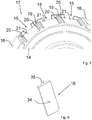
- FIG. 11 shows an enlarged view of the part of the carrier body 14 in the peripheral area of the removed permanent magnets 16 according to FIG Figure 4
- the thus freely visible receiving fields 15 are separated from one another by separating webs 19 which form part of the circumferential region 17 of the rotor 12, and the separating webs 19 extend parallel to the axis of rotation of the rotor, that is, in its height direction.
- On the side of the Separating webs 19 are support strips 20 on which the permanent magnets 16 rest and thus achieve a defined support.
- Well areas 21 extend between the support strips 20, and if the permanent magnets 16 are arranged on the receiving fields 15, they rest laterally on the support strips 20 and are held by an adhesive that is located in the gap thus formed between the permanent magnets 16 and the well area 21 of the Receiving fields 15 is located.
- a defined adhesive gap is achieved via the trough area 21 with a slightly concave curvature, so that an acrylate adhesive, in particular an anaerobic adhesive, can achieve a correspondingly high adhesive performance.
- FIG. 3 shows a single view of a permanent magnet 16, and a front surface 34 forms a curved outer side which, in the glued-on state, points in the direction of the stator, and a rear surface 35 preferably forms a flat surface which points in the direction of the receiving field 15 and with the recess area 21 forms a cavity for the adhesive.
Landscapes
- Engineering & Computer Science (AREA)
- Power Engineering (AREA)
- Manufacturing & Machinery (AREA)
- Power-Operated Mechanisms For Wings (AREA)
- Connection Of Motors, Electrical Generators, Mechanical Devices, And The Like (AREA)
Abstract
Description
- Die Erfindung betrifft einen Türantrieb zur Anordnung an oder in Verbindung mit einer Türanlage, mit dem zumindest ein Flügelelement der Türanlage bewegbar ist, aufweisend eine Motoreinheit mit einem Gehäuse, in dem ein Stator ruhend aufgenommen ist und wobei ein Rotor drehbeweglich im Gehäuse angeordnet ist, der eine Abtriebswelle aufweist, wobei die Abtriebswelle mit dem Flügelelement antreibend in Wirkverbindung gebracht werden kann. Weiterhin betrifft die Erfindung eine Türanlage mit einem solchen Türantrieb, aufweisend wenigstens ein Flügelelement, mit dem der Türantrieb antreibend in Wirkverbindung steht.
- Aus der
DE 10 2008 046 062 A1 ist ein Türantrieb zur Anordnung an einer Türanlage bekannt, und der Antrieb dient zur Bewegung von Flügelelementen der Türanlage, die als automatische Schiebetür ausgebildet ist. Der Türantrieb weist hierfür eine Motoreinheit mit einem Gehäuse auf, und an das Gehäuse der Motoreinheit ist eine Getriebeeinheit angebracht, die als Schneckenradgetriebe ausgeführt ist. Damit ist die Motoreinheit als schnelldrehender Motor konzipiert, und mit der Getriebeeinheit wird die höhere Drehzahl des Rotors der Motoreinheit reduziert auf eine geringere Drehzahl zum Antrieb einer Riemenscheibe, die auf eine Abtriebswelle der Getriebeeinheit aufgesetzt ist. - Über die Riemenscheibe ist ein Zahnriemen geführt, der mit den Flügelelementen der automatischen Schiebetür verbunden wird. Da die Motoreinheit schnelldrehend ausgelegt ist, und die Drehzahl auf die Riemenscheibe reduziert werden muss, ist in Verbindung mit dem Motor die Getriebeeinheit notwendig, wodurch zusätzlicher Bauraum erforderlich wird, und wodurch die Konstruktion des Türantriebs komplexer wird. Die räumliche Dimensionierung des Türantriebs muss an die Notwendigkeit der Getriebeeinheit angepasst werden, und da der Motor eine zylinderförmige Grundform aufweist, nimmt dieser einen Bauraum ein, der in Bezug auf seine Einbauumgebung keine optimale Raumnutzung ermöglicht. Gleiches gilt für ein Schneckenradgetriebe, das insbesondere in Verbindung mit dem Motor quer verläuft und daher sehr bauraumintensiv ist.
- Insbesondere dann, wenn die Abtriebswelle zur direkten Aufnahme einer Riemenscheibe in der eingebauten Türanlage horizontal verlaufen soll, muss die Motorbauform vor allem in Erstreckungsrichtung der Abtriebswelle kurz ausfallen, da es sonst zu Bauraumproblemen beim Einbau der Motoreinheit kommt. Dies liegt darin begründet, dass der mit einem Zahnriemen über die Riemenscheibe angetriebene Läufer im Trägerprofil, der zur Aufnahme eines Flügelelementes beispielsweise einer automatischen Schiebetür dient, noch innerhalb des Trägerprofils an der Riemenscheibe vorbeilaufen können muss. Daher sollte die Motoreinheit in Erstreckungsrichtung der Rotorachse möglichst kurzbauend ausfallen.
- Einen weiteren Türantrieb offenbart die
DE 10 2014 115 932 A1 , und der Türantrieb weist als Grundkörper einen einteiligen quaderförmigen Körper auf, in den Aussparungen zwecks Aufnahme einer Motoreinheit und einer Getriebestufe eingebracht sind. Zur weiteren Aufnahme einer Steuerung, einem Netzteil und dergleichen sind in dem Block weitere Aussparungen und Öffnungen vorgesehen. Der quaderförmige Körper bildet also ein Gehäuse als Träger der einzelnen Komponenten des Türantriebes und ist über der gesamten Abmessung des Antriebes einteilig und gewissermaßen monolithisch ausgeführt. Die Lagerung des Rotors erfolgt mittels einer im quaderförmigen Körper des Türantriebs eingefassten stehenden Achse, wodurch sich aufgrund der einseitig eingefassten Achse ein unvorteilhafter Lastfall ergibt, insbesondere wenn über die Getriebestufe bei großen, schweren Ganzglas-Flügelelementen hohe Kräfte in den Rotor einleitet werden, die über die gegenüberliegend eingefasste, stehende Achse aufgenommen werden müssen. - Grundsätzlich wird bei der Konstruktion von Türantrieben zur Anordnung an oder in Verbindung mit einer Türanlage das Ziel verfolgt, den Türantrieb möglichst kompakt und mit kleinen Abmessungen auszuführen, beispielsweise indem eine Getriebeeinheit oder eine Getriebestufe innerhalb des Türantriebs bereits vermieden wird. Türantriebe werden üblicherweise oberhalb der linear bewegbaren Flügelelemente einer automatischen Schiebetüranlage angeordnet und weisen ein Trägerprofil auf, das einen Grundkörper der Türanlage bildet und im Trägerprofil werden der Türantrieb integriert montiert und gleichermaßen die Flügelelemente linear geführt. Als Verbindungsmittel zwischen dem Türantrieb und den Flügelelementen dient in der Regel ein Zahnriemen, wobei auch andere Zugmittel wie Kettenverbindungen und dergleichen möglich sind. Der Türantrieb bildet dabei mit wenigstens dem Motor, einem Netzteil und einer Steuerung eine eigene Baueinheit, die mit der Anordnung am Trägerprofil in die Türanlage integriert wird.
- Um das Trägerprofil mit einer entsprechenden Blende, einem Gehäuse oder sonstigen Umbauteilen möglichst kleinbauend auszuführen, ist es von Vorteil, auch und insbesondere den Türantrieb selbst möglichst kompakt und mit kleinen Abmessungen auszuführen. Da jedoch Flügelelemente aus Glas große Massen erreichen können, muss der Türantrieb eine hohe Leistungsdichte aufweisen, um trotz kleiner Baumaße derartige Flügelelemente entsprechend stark beschleunigen und auch wieder verzögern zu können, damit die Türanlage auch mit großen Flügelelementen noch eine geforderte Dynamik erreicht.
- Für eine hohe Leistungsdichte und insbesondere einen geräuscharmen Betrieb bieten sich Motoreinheiten in Verbindung mit einem Zahnriemen als Direktantriebe an, bei denen auf der Abtriebswelle der Motoreinheit unmittelbar die Riemenscheibe aufgebracht wird, über die der Zahnriemen gelegt wird, der wiederum unmittelbar mit den Flügelelementen in Verbindung steht. Dadurch kann der Türantrieb geräuschminimal betrieben werden, da keine hohen Motordrehzahlen erreicht werden, und bei entsprechender Auslegung der Motoreinheit können Leistungsdichten bereitgestellt werden, die hinreichend sind, um Flügelelemente von beispielsweise 200kg bis 250kg für den Betrieb einer automatischen Schiebetür hinreichend stark zu beschleunigen und auch wieder zu verzögern.
- Bei einer Motoreinheit mit einem Direktantrieb werden häufig eher niedrige Drehzahlen des Rotors verbunden mit hohen Drehmomenten realisiert, wodurch eine besonders robuste Lagerung des Rotors im Gehäuse der Motoreinheit notwendig wird.
- Der Stator weist gemäß einer regelmäßigen Bauform eine Anzahl von Spulen auf, die bei einem Innenläufer auf radial nach innen weisenden Zähnen des Stators aufgebracht sind. Innerhalb der radial nach innen weisenden Zähne ist der Rotor drehbeweglich aufgenommen und dieser umfasst eine Anzahl von Permanentmagneten. Werden die Spulen elektrisch angesteuert und radial umlaufend bestromt, so wird der Rotor mit den Permanentmagneten in Rotation ersetzt. Die Anbindung der Permanentmagnete an einen Trägerkörper des Rotors ist dabei häufig problematisch. In der Regel werden die Permanentmagnete mit Klammerelementen am Trägerkörper festgesetzt oder mit einer Vergussmasse gemeinsam mit dem Trägerkörper vergossen.
- Aufgabe der Erfindung ist die Schaffung eines Türantriebs mit einer Motoreinheit, die eine hohe Integrationsdichte und eine hohe Leistungsdichte aufweist, und wobei der Motor in Verbindung mit dem wenigstens einen Flügelelement insbesondere als Direktantrieb ausgeführt sein soll. Trotz der hohen Integrationsdichte des Türantriebes soll eine kompakte Ausführung der Motoreinheit erreicht werden, der insbesondere innerhalb des Gehäuses eine hohe Packungsdichte aufweist.
- Diese Aufgabe wird ausgehend von einem Türantrieb gemäß Anspruch 1 und ausgehend von einer Türanlage gemäß Anspruch 15 mit den jeweils kennzeichnenden Merkmalen gelöst. Vorteilhafte Weiterbildungen der Erfindung sind in den abhängigen Ansprüchen und in der Beschreibung angegeben.
- Die Erfindung schließt die technische Lehre ein, dass der Rotor einen Trägerkörper aufweist, an dem Aufnahmefelder ausgebildet sind, auf denen Permanentmagnete aufgeklebt sind.
- Kerngedanke der Erfindung ist eine einfache Ausgestaltung des Rotors mit der Abtriebswelle, aufweisend einen Trägerkörper mit an diesem angeordnete Permanentmagnete. Um eine einfache Anordnung der Permanentmagnete, insbesondere ohne Zuhilfenahme weiterer Elemente, vorzusehen, schlägt die Erfindung vor, Aufnahmefelder am Außenumfang des Trägerkörpers zu schaffen, auf denen die Permanentmagnete aufgeklebt sind. Durch die Schaffung von Aufnahmefeldern werden die Positionen der Permanentmagnete zueinander in Anordnung am Trägerkörper definiert, und die Aufnahmefelder können vorteilhafterweise so ausgeführt werden, dass die Klebeverbindung zur haltenden Anordnung der Permanentmagnete am Trägerkörper ausreichend sein kann.
- Die Aufnahmefelder müssen dabei keine plan ausgeführten Felder bilden, und diese können mit Vorteil wenigstens eine Rechteckform aufweisen, an die die Rechteckform der Permanentmagnete angepasst ist, sodass die Funktion der genauen Positionierung der Permanentmagnete am Trägerkörper hierüber erfüllt wird. Die Rechteckform besitzt eine längere und eine kürzere Kante, wobei die längere Kante parallel verläuft zur Abtriebswelle und damit zur Rotationsachse des Rotors.
- Der Trägerkörper mit einer Anzahl von Aufnahmefeldern an seinem Außenumfang und die Permanentmagnete selbst können so dimensioniert werden, dass ein sehr geringer Spalt zwischen der Außenseite der Permanentmagnete und der Innenseite der Zähne des Stators entsteht. Dadurch erhöht sich das Drehmoment der Motoreinheit bei sonst unveränderten Außenmaßen, und durch den Fall einer Vergussmasse kann die Oberfläche der Permanentmagnete in der Dimensionierung sehr nah herangeführt werden an die innere Oberfläche der Zähne des Stators, auf denen die Spulen mit dem Wicklungsdraht aufgebracht sind.
- Vorteilhafterweise weist der Rotor einen Umfangsbereich auf, der mit den Aufnahmefeldern eine polygonartige Gestalt bildet. Zwischen den Aufnahmefeldern sind vorteilhafterweise Trennstege ausgebildet, die einen Teil des Umfangsbereiches bilden und sich parallel zu einer Rotationsachse der Abtriebswelle und damit des Rotors erstrecken. Die Trennstege trennen zwei zueinander benachbarte Aufnahmefelder und dienen zugleich zur Ausrichtung und Positionierung der aufgeklebten Permanentmagnete. Insbesondere dienen die Trennstege zur Sicherstellung eines definierten Abstandes zwischen zwei benachbarten Permanentmagneten. Die Aufnahmefelder weisen mit besonderem Vorteil zwischen den Trennstegen eine parallel zur Rotationsachse verlaufende längliche Erstreckung auf, und es ist vorgesehen, dass über der Längskante der Aufnahmefelder angrenzend an die Trennstege schmal ausgebildete Auflagestreifen ausgebildet sind. Auf diesen Auflagestreifen können die Permanentmagnete definiert angelegt werden, wobei die zum Trägerkörper weisende Seite der Permanentmagnete beispielsweise plan ausgeführt ist. Die radial nach außen weisende, vordere Fläche der Permanentmagnete kann eine Krümmung aufweisen, die mit dem Radius des Rotors übereinstimmt, während die nach innen weisende, hintere Fläche der Permanentmagnete beispielsweise plan ausgeführt ist, dies jedoch nicht sein muss. Damit ergibt sich eine noch weitere Verbesserung des Spaltes zwischen den Permanentmagneten und den nach innen weisenden Endflächen der Zähne des Stators.
- Die Aufnahmefelder umfassen zwischen den Auflagestreifen einen Muldenbereich, sodass bei Anordnung der Permanentmagnete auf den Aufnahmefeldern ein in der Breite definierter Klebespalt zur Aufnahme von Klebemitteln ausgebildet ist. Mit besonderem Vorteil sind die Aufnahmefelder demgemäß nicht plan ausgeführt, sondern durch eine leichte Vertiefung in den Aufnahmefeldern entstehen Muldenbereiche, die zur Aufnahme von Klebemitteln dienen, insbesondere wenn die zu den Aufnahmefeldern weisende Seite der Permanentmagnete plan ausgeführt ist. Die Tiefe des Muldenbereiches und damit die Ausgestaltung des Klebespaltes ist an das verwendete Klebemittel angepasst. Insbesondere kann ein Acrylat-Klebstoff und/oder ein anaerober Klebstoff zum Einsatz kommen, beispielsweise ein LOCTITE-3342 (TM).
- Es ist weiterhin vorgesehen, dass die Permanentmagnete auf der der Abtriebswelle abgewandten Seite über den Trägerkörper und damit gegebenenfalls auch über den Stator hinausragen können. Das hat den Vorteil, dass im oder am Gehäuse Hallsensoren angebracht werden können, die mit den Permanentmagneten in Wechselwirkung treten können, insbesondere, um eine Ansteuerung für die elektronische Kommutierung des langsam laufenden Elektromotors mittels der Steuerung vorzusehen.
- Weiterhin weist der Trägerkörper in Bezug auf seinen Umlaufquerschnitt eine T-Form auf, was gleichbedeutend beschreiben werden kann mit einer H-Form im Halbschnitt, wodurch jedenfalls innenseitige Aussparungen gebildet sind, die radial umlaufend ausgebildet sind und in denen Lagerelemente zur Lagerung der Abtriebswelle im Gehäuse der Motoreinheit eingebracht werden. Wird die Motoreinheit montiert, so sind die freien Bereiche innerhalb des Trägerkörpers ausgefüllt mit den Lagerelementen, die in Lageraufnahmeabschnitten eingebracht sind, welche wiederum an den Gehäusehälften angeformt sein können. Durch die H-Form im Querschnitt des Trägerkörpers wird die Funktion zur Aufnahme der Permanentmagnete nicht negativ beeinflusst, jedoch können noch auf der Höhe der radialen Innenseiten des Rotationszylinders der Permanentmagnete die Lagerelemente für die Lagerung des Rotors in der Motoreinheit aufgenommen werden, wenigstens zum überwiegenden Teil.
- Nach einer weiteren vorteilhaften Ausführungsform ist die Abtriebswelle mit einem Rotorumlaufabschnitt ausgebildet, auf dem der mit den Permanentmagneten bestückte Trägerkörper aufgebracht ist, wobei die Abtriebswelle insbesondere einen ersten Lagerabschnitt und einen zweiten Lagerabschnitt aufweist, in denen jeweils ein Lagerelement aufgenommen ist, wobei zwischen den Lagerabschnitten der Rotoraufnahmeabschnitt ausgebildet ist.
- Mit weiterem Vorteil ist der Trägerkörper aus einem metallischen Sinterwerkstoff ausgebildet.
- Alternativ kann vorgesehen sein, dass der Trägerkörper aus einem metallischen Gusswerkstoff, insbesondere Feingusswerkstoff, ausgebildet ist.
- Weiterhin besteht vorteilhafterweise die Möglichkeit, dass auf den mit den Permanentmagneten bestückten Trägerkörper ein folienartiger Haltekörper aufgebracht ist. Der folienartige Haltekörper kann durch ein Isolierrohr aus Polyesterfolie ausgebildet sein, die auf den mit dem Permanentmagneten bestückten Trägerkörper aufgeschrumpft ist. Die Polyesterfolie ist dabei so dünn, dass diese noch zusätzlich in den Spalt zwischen der Außenseite der Permanentmagnete und der Innenseite der Zähne des Stators passt. Beispielsweise weist die Polyesterfolie eine Dicke von 0,1 mm auf. Durch die Verwendung einer solchen Polyesterfolie als Isolierrohr wird sichergestellt, dass auch bei einem ungewollten Lösen einer Klebeverbindung ein Permanentmagnet sich nicht vom Trägerkörper entfernt, und somit die Motoreinheit blockieren würde.
- Alternativ ist der folienartige Haltekörper aus einem Wickelkörper aus einer Glasfaserfolie oder einem Glasfasergewebe ausgebildet.
- Die Abtriebswelle kann sich aus einer Stirnseite des Gehäuses heraus erstrecken, sodass auf diesem Abschnitt der Abtriebswelle eine Riemenscheibe aufgebracht ist. Über die Riemenscheibe wird ein Zahnriemen gelegt, der direkt verbunden sein kann mit den Flügelelementen der Türanlage. Damit ist der Türantrieb mit der Motoreinheit als Direktantrieb ausgeführt, und es entfällt die Anordnung eines Getriebes.
- Die Erfindung betrifft weiterhin eine Türanlage mit einem Türantrieb mit den vorstehend beschriebenen Merkmalen. Die Türanlage kann ein Verbindungselement zum Verbinden mit einem Flügelelement aufweisen. Zusätzlich oder alternativ kann die Türanlage wenigstens ein Flügelelement, mit dem der Türantrieb antreibend in Wirkverbindung steht, aufweisen.
- Beispielsweise kann die Türanlage als eine Schiebetüranlage ausgebildet sein. Die Schiebetüranlage kann einen Riemen, insbesondere einen Zahnriemen, umfassen. Das Verbindungselement kann zumindest mittelbar mit dem Riemen verbunden sein. Das Verbindungselement kann als Läufer, insbesondere als Rollwagen, ausgebildet sein. Das Verbindungselement kann in einer Schiene, insbesondere in einer Schiene des Trägerprofils, laufen. Der Riemen kann zwischen Riemenscheiben der Türanlage gespannt sein. Eine der Riemenscheiben kann als die Riemenscheibe des erfindungsgemäßen Türantriebs ausgebildet sein.
- Weitere, die Erfindung verbessernde Maßnahmen werden nachstehend gemeinsam mit der Beschreibung eines bevorzugten Ausführungsbeispiels der Erfindung anhand der Figuren näher dargestellt. Es zeigt:
- Fig. 1
- eine Gesamtansicht des Türantriebs mit einer erfindungsgemäßen Motoreinheit,
- Fig. 2
- eine perspektivische Ansicht der Motoreinheit mit einer entnommenen oberen Gehäusehälfte,
- Fig. 3
- einen Halbschnitt der Motoreinheit ohne eine obere Gehäusehälfte,
- Fig. 4
- eine perspektivische Ansicht des Rotors der Motoreinheit,
- Fig. 5
- eine Detailansicht eines Abschnittes des Rotors und
- Fig. 6
- eine perspektivische Ansicht eines Permanentmagneten.
-
Fig. 1 zeigt eine Gesamtansicht des Türantriebs 100, wie dieser in Verbindung mit einer Türanlage in einem Gebäude installiert werden kann, womit auch die Installation auf Schiffen und in Flugzeugen umfasst sein soll, und ein Türantrieb 100 dieser Art dient beispielsweise als Antrieb für eine automatische Schiebetüranlage. Die Grundstruktur des Türantriebs 100 bildet ein Trägerprofil 29, welches zur einfacheren Ansicht verkürzt dargestellt ist, zudem ist der wesentliche obere Teil des L-förmigen Trägerprofils 29 aufgeschnitten gezeigt, um die weiteren vorliegend wesentlichen Komponenten des Türantriebs 100 sichtbar zu machen. - Als zentraler Bestandteil weist der Türantrieb 100 eine Motoreinheit 1 auf, die die Grundform eines Quaders besitzt, der das Gehäuse 10 der Motoreinheit 1 bildet. Um einen Abtrieb und damit eine Verbindung zu einem nicht näher dargestellten Flügelelement einer Türanlage zu ermöglichen, ist an der Motoreinheit 1 eine Riemenscheibe 27 angeordnet, über die ein Zahnriemen gelegt werden kann, mit dem schließlich die Verbindung zu dem oder den Flügelelementen, beispielsweise den Glasschiebeelementen, hergestellt wird.
- Benachbart zur Motoreinheit 1 weist der Türantrieb 100 ein Netzteil 30 und eine Steuerung 31 auf, und das Netzteil 30 und die Steuerung 31 sind an sich gegenüberliegenden Seiten der Motoreinheit 1 angeordnet. Die Motoreinheit 1 ist mit einem ersten Flanschelement 32 am Trägerprofil 29 befestigt, wobei das erste Flanschelement 32 zugleich das Netzteil 30 haltend mit aufnimmt. Weiterhin ist die Motoreinheit 1 mit einem zweiten Flanschelement 33 mit dem Trägerprofil 29 verbunden, wobei das zweite Flanschelement 33 zugleich die Steuerung 31 aufnimmt. Alternativ ist auch die Ausführung eines einzigen Flansches möglich, um wenigstens die Motoreinheit 1, das Netzteil 30 und die Steuerung 31 aufzunehmen, ferner besteht die Möglichkeit, dass die Motoreinheit 1, das Netzteil 30 und/oder die Steuerung 31 jeweils zugeordnete separate Flanschelemente zur Anordnung im oder am Trägerprofil 29 aufweisen.
-
Fig. 2 zeigt eine perspektivische Ansicht der Motoreinheit 1 mit dem Gehäuse 10, wobei lediglich eine untere Gehäusehälfte dargestellt ist, und die obere Gehäusehälfte ist zur Darstellung weiterer Komponenten der Motoreinheit 1 entnommen. Am Gehäuse 10, insbesondere betreffend die untere Gehäusehälfte gemäß der Darstellung, ist innenseitig ein Stator 11 montiert, und innerhalb des Stators 11 ist ein Rotor 12 in einer Abtriebswelle 13 drehbar aufgenommen. Oberhalb des nicht dargestellten oberen Teils des Gehäuses ist eine Riemenscheibe 27 auf der Abtriebswelle 13 aufgebracht, sodass die Motoreinheit 1 als Direktantrieb ausgeführt ist, und es erstreckt sich lediglich ein Zahnriemen zwischen der Motoreinheit 1 und dem Flügelelementen der Türanlage, beispielsweise einer automatischen Schiebetür. -
Fig. 3 zeigt in einer quergeschnittenen Ansicht die Motoreinheit 1 mit dem Rotor 12, der als wesentliche Bestandteile die Abtriebswelle 13 und einen Trägerkörper 14 aufweist, und außenseitig am Trägerkörper 14 sind in regelmäßigen Abständen Permanentmagnete 16 aufgebracht. Auf einem aus dem Gehäuse 10 hervorstehenden Teil ist auf der Abtriebswelle 13 die Riemenscheibe 27 aufgebracht. - Die Abtriebswelle 13 ist mit einem Rotoraufnahmeabschnitt 24 ausgebildet, auf dem der mit den Permanentmagneten 16 bestückte Trägerkörper 14 aufgebracht ist. Weiterhin weist die Abtriebswelle 13 einen ersten Lagerabschnitt 25 und einen zweiten Lagerabschnitt 26 auf, auf denen jeweils ein Lagerelement 23 aufgenommen ist. Der Rotoraufnahmeabschnitt 24 befindet sich dabei mit Bezug auf die Längsachse der Abtriebswelle 13 zwischen den Lagerabschnitten 25 und 26.
- Der Trägerkörper 14 weist eine T-Form in Bezug auf seinen Umlaufquerschnitt auf, wobei die Form des Trägerkörpers 14 auch mit einer H-Form in Bezug auf seinen gesamten Querschnitt beschrieben werden kann. Dadurch werden innenseitige Aussparungen 22 gebildet, in denen die Lagerelemente 23 eingebracht sind.
-
Fig. 4 zeigt eine perspektivische Ansicht des Rotors 12 mit der Abtriebswelle 13 und mit dem Trägerkörper 14, wobei eine untere Aussparung 22 zu sehen ist. Innerhalb der einzigen sichtbaren Aussparung 22 innerhalb des Trägerkörpers 14 ist beispielhaft ein Lagerelement 23 eingesetzt gezeigt, das zur drehbaren Aufnahme der Abtriebswelle 13 dient. Auf dem Außenumfang weist der Trägerkörper 14 Aufnahmefelder 15 auf, auf denen die Permanentmagnete 16 aufgebracht sind, wobei bei drei Aufnahmefeldern 15 beispielhaft kein Permanentmagnet 16 gezeigt ist. -
Fig. 5 zeigt eine vergrößerte Ansicht des Teils des Trägerkörpers 14 im Umfangsbereich der entnommenen Permanentmagnete 16 gemäßFigur 4 , Die damit frei sichtbaren Aufnahmefelder 15 sind voneinander mit Trennstegen 19 getrennt, die einen Teil des Umfangsbereiches 17 des Rotors 12 bilden, und die Trennstege 19 erstrecken sich parallel zur Rotationsachse des Rotors, also in seiner Höhenrichtung. Seitlich an den Trennstegen 19 sind Auflagestreifen 20 ausgebildet, auf denen die Permanentmagnete 16 aufliegend und somit eine definierte Auflage erlangen. - Zwischen den Auflagestreifen 20 erstrecken sich Muldenbereiche 21, und sind die Permanentmagnete 16 auf den Aufnahmefeldern 15 angeordnet, liegen diese seitlich auf den Auflagestreifen 20 auf und werden durch ein Klebemittel gehalten, das sich im so gebildeten Spalt zwischen den Permanentmagneten 16 und dem Muldenbereich 21 der Aufnahmefelder 15 befindet. Über den Muldenbereich 21 mit einer leicht konkaven Wölbung wird ein definierter Klebespalt erreicht, sodass ein Acrylatkleber, insbesondere ein anaerober Kleber, eine entsprechend hohe Klebeleistung erreichen kann. Damit ist sichergestellt, dass sich die scheren Permanentmagnete 16 im Betrieb der Motoreinheit 1 nicht lösen, wobei die Motoreinheit 1 aufgrund der Direktantriebsverbindung zum Zahnriemen und damit zu einem Flügelelement einer Türanlage als Langsamläufer ausgebildet ist, sodass der Rotor keine hohen Drehzahlen erreicht, und damit die Fließkräfte der Permanentmagnete 16 im Betrieb der Motoreinheit 1 auch nicht zu hoch werden.
-
Fig. 6 zeigt schließlich eine Einzelansicht eines Permanentmagneten 16, und eine vordere Fläche 34 bildet eine gekrümmte Außenseite, die im aufgeklebten Zustand in Richtung zum Stator weist, und eine hintere Fläche 35 bildet vorzugsweise eine Planfläche, die in Richtung zum Aufnahmefeld 15 weist und mit dem Muldenbereich 21 eine Kavität für das Klebemittel bildet. - Die Erfindung beschränkt sich in ihrer Ausführung nicht auf das vorstehend angegebene bevorzugte Ausführungsbeispiel. Vielmehr ist eine Anzahl von Varianten denkbar, welche von der dargestellten Lösung auch bei grundsätzlich anders gearteten Ausführungen Gebrauch macht. Sämtliche aus den Ansprüchen, der Beschreibung oder den Zeichnungen hervorgehenden Merkmale und/oder Vorteile, einschließlich konstruktiver Einzelheiten oder räumlicher Anordnungen, können sowohl für sich als auch in den verschiedensten Kombinationen erfindungswesentlich sein.
-
- 100
- Türantrieb
- 1
- Motoreinheit
- 10
- Gehäuse
- 11
- Stator
- 12
- Rotor
- 13
- Abtriebswelle
- 14
- Trägerkörper
- 15
- Aufnahmefelder
- 16
- Permanentmagnete
- 17
- Umfangsbereich
- 18
- Rotationsachse
- 19
- Trennstege
- 20
- Auflagestreifen
- 21
- Muldenbereich
- 22
- Aussparung
- 23
- Lagerelement
- 24
- Rotoraufnahmeabschnitt
- 25
- erster Lagerabschnitt
- 26
- zweiter Lagerabschnitt
- 27
- Riemenscheibe
- 28
- Stirnseite
- 29
- Trägerprofil
- 30
- Netzteil
- 31
- Steuerung
- 32
- erstes Flanschelement
- 33
- zweites Flanschelement
- 34
- vordere Fläche
- 35
- hintere Fläche
Claims (15)
- Türantrieb (100) zur Anordnung an oder in Verbindung mit einer Türanlage, mit dem zumindest ein Flügelelement der Türanlage bewegbar ist, aufweisend eine Motoreinheit (1) mit einem Gehäuse (10), in dem ein Stator (11) ruhend aufgenommen ist und wobei ein Rotor (12) drehbeweglich im Gehäuse (10) angeordnet ist, der eine Abtriebswelle (13) aufweist, wobei die Abtriebswelle (13) mit dem Flügelelement antreibend in Wirkverbindung bringbar ist,
dadurch gekennzeichnet, dass der Rotor (12) einen Trägerkörper (14) aufweist, an dem Aufnahmefelder (15) ausgebildet sind, auf denen Permanentmagnete (16) aufgeklebt sind. - Türantrieb (100) nach Anspruch 1, dadurch gekennzeichnet, dass der Rotor (12) einen Umfangsbereich (17) aufweist, der mit den Aufnahmefeldern (15) eine polygonartige Gestalt bildet.
- Türantrieb (100) nach Anspruch 1 oder 2, dadurch gekennzeichnet, dass der Rotor (12) eine Rotationsachse (18) aufweist, wobei zwischen den Aufnahmefeldern (15) Trennstege (19) ausgebildet sind, die einen Teil des Umfangsbereiches (17) bilden und sich parallel zur Rotationsachse (18) erstrecken.
- Türantrieb (100) nach Anspruch 3, dadurch gekennzeichnet, dass die Aufnahmefelder (15) zwischen den Trennstegen (19) eine parallel zur Rotationsachse (18) verlaufende längliche Erstreckung aufweisen und über ihrer Längskante mit seitlichen an die Trennstege (19) angrenzenden Auflagestreifen (20) ausgebildet sind.
- Türantrieb (100) nach Anspruch 4, dadurch gekennzeichnet, dass die Aufnahmefelder (15) zwischen den Auflagestreifen (20) einen Muldenbereich (21) aufweisen, sodass bei Anordnung der Permanentmagnete (16) auf den Aufnahmefeldern (15) ein definierter Klebespalt zur Aufnahme von Klebemittel ausgebildet wird.
- Türantrieb (100) nach einem der vorgenannten Ansprüche, dadurch gekennzeichnet, dass die Permanentmagnete (16) auf der der Abtriebswelle (13) abgewandten Seite über den Trägerkörper (14) hinausragen.
- Türantrieb (100) nach einem der vorgenannten Ansprüche, dadurch gekennzeichnet, dass der Trägerkörper (14) in Bezug auf seinen Umlaufquerschnitt eine T-Form und/oder in Bezug auf seinen Halbschnitt eine H-Form aufweist, wodurch innenseitige Aussparungen (22) gebildet sind, in denen Lagerelemente (23) eingebracht sind.
- Türantrieb (100) nach einem der vorgenannten Ansprüche, dadurch gekennzeichnet, dass die Abtriebswelle (13) mit einem Rotoraufnahmeabschnitt (24) ausgebildet ist, auf dem der mit den Permanentmagneten (16) bestückte Trägerkörper (14) aufgebracht ist und/oder wobei die Abtriebswelle (13) einen ersten Lagerabschnitt (25) und einen zweiten Lagerabschnitt (26) aufweist, auf denen jeweils ein Lagerelement (23) aufgenommen ist, wobei zwischen den Lagerabschnitten (25, 26) der Rotoraufnahmeabschnitt (24) ausgebildet ist.
- Türantrieb (100) nach einem der vorgenannten Ansprüche, dadurch gekennzeichnet, dass der Trägerkörper (14) aus einem metallischen Sinterwerkstoff oder Gusswerkstoff ausgebildet ist.
- Türantrieb (100) nach einem der vorgenannten Ansprüche, dadurch gekennzeichnet, dass auf dem mit den Permanentmagneten (16) bestückten Trägerkörper (14) ein folienartiger Haltekörper aufgebracht ist.
- Türantrieb (100) nach Anspruch 10, dadurch gekennzeichnet, dass der folienartige Haltekörper ein Isolierrohr aus Polyesterfolie aufweist und auf den mit den Permanentmagneten (16) bestückten Trägerkörper (14) aufschrumpfbar ist.
- Türantrieb (100) nach Anspruch 10 oder 11, dadurch gekennzeichnet, dass der folienartige Haltekörper aus einem Wickelkörper aus einer Glasfaserfolie oder einem Glasfasergewebe gebildet ist.
- Türantrieb (100) nach einem der vorgenannten Ansprüche, dadurch gekennzeichnet, dass sich die Abtriebswelle (13) abschnittsweise aus einer Stirnseite (28) des Gehäuses (10 heraus erstreckt, sodass auf diesem Abschnitt der Abtriebswelle (1) eine Riemenscheibe (27) aufgebracht ist.
- Türantrieb (100) nach einem der vorgenannten Ansprüche, dadurch gekennzeichnet, dass der Klebstoff zum Aufkleben der Permanentmagnete (16) auf den Trägerkörper (14) des Rotors (12) einen Acrylatkleber umfasst und/oder einen anaeroben Klebstoff bildet.
- Türanlage mit einem Türantrieb (100) gemäß einem der vorgenannten Ansprüche, aufweisend wenigstens ein Verbindungselement zum Verbinden mit einem Flügelelement und/oder wenigstens ein Flügelelement, mit dem der Türantrieb (100) antreibend in Wirkverbindung steht.
Priority Applications (6)
| Application Number | Priority Date | Filing Date | Title |
|---|---|---|---|
| ES19214435T ES2985214T3 (es) | 2019-12-09 | 2019-12-09 | Accionamiento de puerta con una unidad de motor de gran potencia, de pequeño tamaño |
| EP19214435.0A EP3835531B1 (de) | 2019-12-09 | 2019-12-09 | Türantrieb mit einer leistungsstarken, kleinbauenden motoreinheit |
| AU2020403070A AU2020403070B2 (en) | 2019-12-09 | 2020-12-03 | Door drive with a small high-performance motor unit |
| CN202080084428.2A CN114787472B (zh) | 2019-12-09 | 2020-12-03 | 具有功率大的、小构造的马达单元的门驱动器 |
| PCT/EP2020/084535 WO2021115930A1 (de) | 2019-12-09 | 2020-12-03 | Türantrieb mit einer leistungsstarken, kleinbauenden motoreinheit |
| US17/782,862 US12113399B2 (en) | 2019-12-09 | 2020-12-03 | Door drive with a small high-performance motor unit |
Applications Claiming Priority (1)
| Application Number | Priority Date | Filing Date | Title |
|---|---|---|---|
| EP19214435.0A EP3835531B1 (de) | 2019-12-09 | 2019-12-09 | Türantrieb mit einer leistungsstarken, kleinbauenden motoreinheit |
Publications (3)
| Publication Number | Publication Date |
|---|---|
| EP3835531A1 true EP3835531A1 (de) | 2021-06-16 |
| EP3835531B1 EP3835531B1 (de) | 2024-03-27 |
| EP3835531C0 EP3835531C0 (de) | 2024-03-27 |
Family
ID=68840909
Family Applications (1)
| Application Number | Title | Priority Date | Filing Date |
|---|---|---|---|
| EP19214435.0A Active EP3835531B1 (de) | 2019-12-09 | 2019-12-09 | Türantrieb mit einer leistungsstarken, kleinbauenden motoreinheit |
Country Status (6)
| Country | Link |
|---|---|
| US (1) | US12113399B2 (de) |
| EP (1) | EP3835531B1 (de) |
| CN (1) | CN114787472B (de) |
| AU (1) | AU2020403070B2 (de) |
| ES (1) | ES2985214T3 (de) |
| WO (1) | WO2021115930A1 (de) |
Families Citing this family (2)
| Publication number | Priority date | Publication date | Assignee | Title |
|---|---|---|---|---|
| EP4485754A1 (de) * | 2023-06-27 | 2025-01-01 | dormakaba Deutschland GmbH | Permanentmagnetanordnung, axialflussmaschine und elektromechanischer antrieb |
| DE102024134065A1 (de) * | 2024-11-20 | 2026-05-21 | Robert Bosch Gesellschaft mit beschränkter Haftung | Rotor für eine elektronisch kommutierte Elektromaschine und Elektromaschine |
Citations (5)
| Publication number | Priority date | Publication date | Assignee | Title |
|---|---|---|---|---|
| DE102008046062A1 (de) | 2008-09-08 | 2010-03-11 | Dorma Gmbh + Co. Kg | Nachrüstsatz mit einer Antriebseinheit, insbesondere für eine automatische Schiebetür |
| DE102008047310A1 (de) * | 2008-09-16 | 2010-04-15 | Elau Gmbh | Elektromotor mit sichelförmigen Magnetprofilen |
| US20100244607A1 (en) * | 2009-03-31 | 2010-09-30 | Mitsubishi Electric Corporation | Rotor of rotary electric machine and method of manufacturing the same |
| DE102014115931A1 (de) * | 2014-10-31 | 2016-05-04 | Dorma Deutschland Gmbh | Türantrieb |
| DE102014115932A1 (de) | 2014-10-31 | 2016-05-04 | Dorma Deutschland Gmbh | Türantrieb |
Family Cites Families (10)
| Publication number | Priority date | Publication date | Assignee | Title |
|---|---|---|---|---|
| US4594525A (en) * | 1983-06-27 | 1986-06-10 | General Electric Company | Rotatable assembly for a dynamoelectric machine |
| US5397951A (en) * | 1991-11-29 | 1995-03-14 | Fanuc Ltd. | Rotor for a synchronous rotary machine |
| DE502005010177D1 (de) * | 2005-07-29 | 2010-10-14 | Siemens Ag | Permanentmagnetrotor für eine bürstenlose elektrische Maschine |
| DE202006007139U1 (de) * | 2006-02-10 | 2006-10-26 | Gretsch-Unitas GmbH Baubeschläge | Betätigungsvorrichtung für Türen |
| EP2348612A1 (de) * | 2010-01-20 | 2011-07-27 | Siemens Aktiengesellschaft | Magnetischer Komponententeil für eine Rotoranordnung |
| DK2555384T3 (en) * | 2011-08-01 | 2016-10-03 | Siemens Ag | Field structure of an electrical machine |
| JP5958502B2 (ja) * | 2013-12-06 | 2016-08-02 | 株式会社デンソー | 回転子およびそれを用いた回転電機 |
| DE102014115924A1 (de) * | 2014-10-31 | 2016-05-04 | Dorma Deutschland Gmbh | Türantrieb |
| JP6464114B2 (ja) * | 2016-05-20 | 2019-02-06 | ファナック株式会社 | 回転電機の回転子構造および回転電機 |
| CN110212663B (zh) * | 2019-06-19 | 2025-03-28 | 宁波富佳实业股份有限公司 | 外转子无刷电机 |
-
2019
- 2019-12-09 EP EP19214435.0A patent/EP3835531B1/de active Active
- 2019-12-09 ES ES19214435T patent/ES2985214T3/es active Active
-
2020
- 2020-12-03 CN CN202080084428.2A patent/CN114787472B/zh active Active
- 2020-12-03 AU AU2020403070A patent/AU2020403070B2/en active Active
- 2020-12-03 US US17/782,862 patent/US12113399B2/en active Active
- 2020-12-03 WO PCT/EP2020/084535 patent/WO2021115930A1/de not_active Ceased
Patent Citations (5)
| Publication number | Priority date | Publication date | Assignee | Title |
|---|---|---|---|---|
| DE102008046062A1 (de) | 2008-09-08 | 2010-03-11 | Dorma Gmbh + Co. Kg | Nachrüstsatz mit einer Antriebseinheit, insbesondere für eine automatische Schiebetür |
| DE102008047310A1 (de) * | 2008-09-16 | 2010-04-15 | Elau Gmbh | Elektromotor mit sichelförmigen Magnetprofilen |
| US20100244607A1 (en) * | 2009-03-31 | 2010-09-30 | Mitsubishi Electric Corporation | Rotor of rotary electric machine and method of manufacturing the same |
| DE102014115931A1 (de) * | 2014-10-31 | 2016-05-04 | Dorma Deutschland Gmbh | Türantrieb |
| DE102014115932A1 (de) | 2014-10-31 | 2016-05-04 | Dorma Deutschland Gmbh | Türantrieb |
Also Published As
| Publication number | Publication date |
|---|---|
| WO2021115930A1 (de) | 2021-06-17 |
| US20230017823A1 (en) | 2023-01-19 |
| EP3835531B1 (de) | 2024-03-27 |
| EP3835531C0 (de) | 2024-03-27 |
| US12113399B2 (en) | 2024-10-08 |
| AU2020403070A1 (en) | 2022-06-09 |
| CN114787472A (zh) | 2022-07-22 |
| AU2020403070B2 (en) | 2026-03-05 |
| CN114787472B (zh) | 2025-08-19 |
| ES2985214T3 (es) | 2024-11-04 |
Similar Documents
| Publication | Publication Date | Title |
|---|---|---|
| EP1657800B1 (de) | Permanentmagnet-Rotor | |
| EP3593441B1 (de) | Elektromotor | |
| DE102016216888A1 (de) | Antriebsvorrichtung für einen Fensterheber, mit einem Lagerelement zum Fixieren eines Stators in einem Gehäuse | |
| DE102016216890A1 (de) | Antriebsvorrichtung für einen Fensterheber, mit einem Außenläufermotor | |
| WO2004042891A1 (de) | Permanentmagnetmaschine mit axialem luftspal | |
| WO2021115930A1 (de) | Türantrieb mit einer leistungsstarken, kleinbauenden motoreinheit | |
| DE102012200882A1 (de) | Elektrische Maschine mit einer Klemmnase zur Magnetbefestigung | |
| EP3817195A1 (de) | Rotor für eine elektrische maschine, zugehöriges herstellungsverfahren und elektrische maschine zum antreiben eines fahrzeugs | |
| EP1826359A1 (de) | Durchgangssperre | |
| EP1563587B1 (de) | Antriebsvorrichtung für verstelleinrichtungen in kraftfahrzeugen | |
| EP3835528B1 (de) | Türanlage mit einer motoreinheit, aufweisend eine vorteilhafte grundform | |
| EP3835534B1 (de) | Türantrieb mit einer motoreinheit | |
| EP3035497B1 (de) | Karusselltür | |
| EP4445477A1 (de) | Stator für eine axialflussmaschine | |
| EP3835529A1 (de) | Türantrieb mit einer motoreinheit, aufweisend eine vorteilhafte lageranordnung zur lagerung einer abtriebswelle | |
| EP3835532B1 (de) | Türantrieb mit einer einfach aufgebauten motoreinheit hoher integrationsdichte | |
| DE202015100189U1 (de) | Antriebsvorrichtung für den dreh- und kippbar an einem Blendrahmen angeordneten Flügel eines Fensters oder einer Tür | |
| EP3835530B1 (de) | Türantrieb mit einer motoreinheit, aufweisend eine vorteilhafte elektrische beschaltung | |
| EP3835533B1 (de) | Türantrieb mit einer motoreinheit, aufweisend eine geringe baugrösse | |
| DE102018131847A1 (de) | Käfig zur relativen Positionierung von Magnetkörpern an einem Blechpaket einer elektrischen Maschine | |
| EP4089284B1 (de) | Nassläuferpumpe | |
| DE19508384C2 (de) | Magnet-Anordnung in einer Magnetleiste für einen elektrischen Linearmotor | |
| EP0702447A2 (de) | Gehäuseloser Elektromotor mit Lagerschilden | |
| DE102020114323A1 (de) | Rotor einer elektrischen Rotationsmaschine, Verfahren zur Herstellung eines Rotors einer elektrischen Rotationsmaschine sowie elektrische Rotationsmaschine | |
| DE2846280B2 (de) | Käfigläufer für einen Induktionsmotor mit axialem Luftspalt |
Legal Events
| Date | Code | Title | Description |
|---|---|---|---|
| PUAI | Public reference made under article 153(3) epc to a published international application that has entered the european phase |
Free format text: ORIGINAL CODE: 0009012 |
|
| STAA | Information on the status of an ep patent application or granted ep patent |
Free format text: STATUS: THE APPLICATION HAS BEEN PUBLISHED |
|
| AK | Designated contracting states |
Kind code of ref document: A1 Designated state(s): AL AT BE BG CH CY CZ DE DK EE ES FI FR GB GR HR HU IE IS IT LI LT LU LV MC MK MT NL NO PL PT RO RS SE SI SK SM TR |
|
| STAA | Information on the status of an ep patent application or granted ep patent |
Free format text: STATUS: REQUEST FOR EXAMINATION WAS MADE |
|
| 17P | Request for examination filed |
Effective date: 20211216 |
|
| RBV | Designated contracting states (corrected) |
Designated state(s): AL AT BE BG CH CY CZ DE DK EE ES FI FR GB GR HR HU IE IS IT LI LT LU LV MC MK MT NL NO PL PT RO RS SE SI SK SM TR |
|
| RIC1 | Information provided on ipc code assigned before grant |
Ipc: E05F 15/643 20150101ALN20230831BHEP Ipc: E05F 15/632 20150101ALN20230831BHEP Ipc: H02K 15/03 20060101ALI20230831BHEP Ipc: H02K 1/278 20220101ALI20230831BHEP Ipc: E05F 15/603 20150101AFI20230831BHEP |
|
| RIC1 | Information provided on ipc code assigned before grant |
Ipc: E05F 15/643 20150101ALN20230925BHEP Ipc: E05F 15/632 20150101ALN20230925BHEP Ipc: H02K 15/03 20060101ALI20230925BHEP Ipc: H02K 1/278 20220101ALI20230925BHEP Ipc: E05F 15/603 20150101AFI20230925BHEP |
|
| GRAP | Despatch of communication of intention to grant a patent |
Free format text: ORIGINAL CODE: EPIDOSNIGR1 |
|
| STAA | Information on the status of an ep patent application or granted ep patent |
Free format text: STATUS: GRANT OF PATENT IS INTENDED |
|
| INTG | Intention to grant announced |
Effective date: 20231110 |
|
| GRAS | Grant fee paid |
Free format text: ORIGINAL CODE: EPIDOSNIGR3 |
|
| GRAA | (expected) grant |
Free format text: ORIGINAL CODE: 0009210 |
|
| STAA | Information on the status of an ep patent application or granted ep patent |
Free format text: STATUS: THE PATENT HAS BEEN GRANTED |
|
| AK | Designated contracting states |
Kind code of ref document: B1 Designated state(s): AL AT BE BG CH CY CZ DE DK EE ES FI FR GB GR HR HU IE IS IT LI LT LU LV MC MK MT NL NO PL PT RO RS SE SI SK SM TR |
|
| REG | Reference to a national code |
Ref country code: GB Ref legal event code: FG4D Free format text: NOT ENGLISH |
|
| REG | Reference to a national code |
Ref country code: CH Ref legal event code: EP |
|
| REG | Reference to a national code |
Ref country code: DE Ref legal event code: R096 Ref document number: 502019010885 Country of ref document: DE |
|
| REG | Reference to a national code |
Ref country code: IE Ref legal event code: FG4D Free format text: LANGUAGE OF EP DOCUMENT: GERMAN |
|
| U01 | Request for unitary effect filed |
Effective date: 20240417 |
|
| U07 | Unitary effect registered |
Designated state(s): AT BE BG DE DK EE FI FR IT LT LU LV MT NL PT SE SI Effective date: 20240424 |
|
| PG25 | Lapsed in a contracting state [announced via postgrant information from national office to epo] |
Ref country code: GR Free format text: LAPSE BECAUSE OF FAILURE TO SUBMIT A TRANSLATION OF THE DESCRIPTION OR TO PAY THE FEE WITHIN THE PRESCRIBED TIME-LIMIT Effective date: 20240628 |
|
| PG25 | Lapsed in a contracting state [announced via postgrant information from national office to epo] |
Ref country code: RS Free format text: LAPSE BECAUSE OF FAILURE TO SUBMIT A TRANSLATION OF THE DESCRIPTION OR TO PAY THE FEE WITHIN THE PRESCRIBED TIME-LIMIT Effective date: 20240627 Ref country code: HR Free format text: LAPSE BECAUSE OF FAILURE TO SUBMIT A TRANSLATION OF THE DESCRIPTION OR TO PAY THE FEE WITHIN THE PRESCRIBED TIME-LIMIT Effective date: 20240327 |
|
| PG25 | Lapsed in a contracting state [announced via postgrant information from national office to epo] |
Ref country code: RS Free format text: LAPSE BECAUSE OF FAILURE TO SUBMIT A TRANSLATION OF THE DESCRIPTION OR TO PAY THE FEE WITHIN THE PRESCRIBED TIME-LIMIT Effective date: 20240627 Ref country code: NO Free format text: LAPSE BECAUSE OF FAILURE TO SUBMIT A TRANSLATION OF THE DESCRIPTION OR TO PAY THE FEE WITHIN THE PRESCRIBED TIME-LIMIT Effective date: 20240627 Ref country code: HR Free format text: LAPSE BECAUSE OF FAILURE TO SUBMIT A TRANSLATION OF THE DESCRIPTION OR TO PAY THE FEE WITHIN THE PRESCRIBED TIME-LIMIT Effective date: 20240327 Ref country code: GR Free format text: LAPSE BECAUSE OF FAILURE TO SUBMIT A TRANSLATION OF THE DESCRIPTION OR TO PAY THE FEE WITHIN THE PRESCRIBED TIME-LIMIT Effective date: 20240628 |
|
| PG25 | Lapsed in a contracting state [announced via postgrant information from national office to epo] |
Ref country code: IS Free format text: LAPSE BECAUSE OF FAILURE TO SUBMIT A TRANSLATION OF THE DESCRIPTION OR TO PAY THE FEE WITHIN THE PRESCRIBED TIME-LIMIT Effective date: 20240727 |
|
| PG25 | Lapsed in a contracting state [announced via postgrant information from national office to epo] |
Ref country code: SM Free format text: LAPSE BECAUSE OF FAILURE TO SUBMIT A TRANSLATION OF THE DESCRIPTION OR TO PAY THE FEE WITHIN THE PRESCRIBED TIME-LIMIT Effective date: 20240327 |
|
| PG25 | Lapsed in a contracting state [announced via postgrant information from national office to epo] |
Ref country code: CZ Free format text: LAPSE BECAUSE OF FAILURE TO SUBMIT A TRANSLATION OF THE DESCRIPTION OR TO PAY THE FEE WITHIN THE PRESCRIBED TIME-LIMIT Effective date: 20240327 |
|
| PG25 | Lapsed in a contracting state [announced via postgrant information from national office to epo] |
Ref country code: PL Free format text: LAPSE BECAUSE OF FAILURE TO SUBMIT A TRANSLATION OF THE DESCRIPTION OR TO PAY THE FEE WITHIN THE PRESCRIBED TIME-LIMIT Effective date: 20240327 |
|
| PG25 | Lapsed in a contracting state [announced via postgrant information from national office to epo] |
Ref country code: SK Free format text: LAPSE BECAUSE OF FAILURE TO SUBMIT A TRANSLATION OF THE DESCRIPTION OR TO PAY THE FEE WITHIN THE PRESCRIBED TIME-LIMIT Effective date: 20240327 |
|
| PG25 | Lapsed in a contracting state [announced via postgrant information from national office to epo] |
Ref country code: SM Free format text: LAPSE BECAUSE OF FAILURE TO SUBMIT A TRANSLATION OF THE DESCRIPTION OR TO PAY THE FEE WITHIN THE PRESCRIBED TIME-LIMIT Effective date: 20240327 Ref country code: SK Free format text: LAPSE BECAUSE OF FAILURE TO SUBMIT A TRANSLATION OF THE DESCRIPTION OR TO PAY THE FEE WITHIN THE PRESCRIBED TIME-LIMIT Effective date: 20240327 Ref country code: RO Free format text: LAPSE BECAUSE OF FAILURE TO SUBMIT A TRANSLATION OF THE DESCRIPTION OR TO PAY THE FEE WITHIN THE PRESCRIBED TIME-LIMIT Effective date: 20240327 Ref country code: PL Free format text: LAPSE BECAUSE OF FAILURE TO SUBMIT A TRANSLATION OF THE DESCRIPTION OR TO PAY THE FEE WITHIN THE PRESCRIBED TIME-LIMIT Effective date: 20240327 Ref country code: IS Free format text: LAPSE BECAUSE OF FAILURE TO SUBMIT A TRANSLATION OF THE DESCRIPTION OR TO PAY THE FEE WITHIN THE PRESCRIBED TIME-LIMIT Effective date: 20240727 Ref country code: CZ Free format text: LAPSE BECAUSE OF FAILURE TO SUBMIT A TRANSLATION OF THE DESCRIPTION OR TO PAY THE FEE WITHIN THE PRESCRIBED TIME-LIMIT Effective date: 20240327 |
|
| REG | Reference to a national code |
Ref country code: ES Ref legal event code: FG2A Ref document number: 2985214 Country of ref document: ES Kind code of ref document: T3 Effective date: 20241104 |
|
| REG | Reference to a national code |
Ref country code: DE Ref legal event code: R097 Ref document number: 502019010885 Country of ref document: DE |
|
| U20 | Renewal fee for the european patent with unitary effect paid |
Year of fee payment: 6 Effective date: 20241227 |
|
| PLBE | No opposition filed within time limit |
Free format text: ORIGINAL CODE: 0009261 |
|
| STAA | Information on the status of an ep patent application or granted ep patent |
Free format text: STATUS: NO OPPOSITION FILED WITHIN TIME LIMIT |
|
| 26N | No opposition filed |
Effective date: 20250103 |
|
| PG25 | Lapsed in a contracting state [announced via postgrant information from national office to epo] |
Ref country code: MC Free format text: LAPSE BECAUSE OF FAILURE TO SUBMIT A TRANSLATION OF THE DESCRIPTION OR TO PAY THE FEE WITHIN THE PRESCRIBED TIME-LIMIT Effective date: 20240327 |
|
| PG25 | Lapsed in a contracting state [announced via postgrant information from national office to epo] |
Ref country code: IE Free format text: LAPSE BECAUSE OF NON-PAYMENT OF DUE FEES Effective date: 20241209 |
|
| REG | Reference to a national code |
Ref country code: CH Ref legal event code: U11 Free format text: ST27 STATUS EVENT CODE: U-0-0-U10-U11 (AS PROVIDED BY THE NATIONAL OFFICE) Effective date: 20260101 |
|
| PGFP | Annual fee paid to national office [announced via postgrant information from national office to epo] |
Ref country code: GB Payment date: 20251219 Year of fee payment: 7 |
|
| U20 | Renewal fee for the european patent with unitary effect paid |
Year of fee payment: 7 Effective date: 20251230 |
|
| PGFP | Annual fee paid to national office [announced via postgrant information from national office to epo] |
Ref country code: ES Payment date: 20260130 Year of fee payment: 7 |
|
| PGFP | Annual fee paid to national office [announced via postgrant information from national office to epo] |
Ref country code: CH Payment date: 20260101 Year of fee payment: 7 |
|
| PG25 | Lapsed in a contracting state [announced via postgrant information from national office to epo] |
Ref country code: CY Free format text: LAPSE BECAUSE OF FAILURE TO SUBMIT A TRANSLATION OF THE DESCRIPTION OR TO PAY THE FEE WITHIN THE PRESCRIBED TIME-LIMIT Effective date: 20240327 |
|
| PG25 | Lapsed in a contracting state [announced via postgrant information from national office to epo] |
Ref country code: TR Free format text: LAPSE BECAUSE OF FAILURE TO SUBMIT A TRANSLATION OF THE DESCRIPTION OR TO PAY THE FEE WITHIN THE PRESCRIBED TIME-LIMIT Effective date: 20240327 |
|
| PG25 | Lapsed in a contracting state [announced via postgrant information from national office to epo] |
Ref country code: HU Free format text: LAPSE BECAUSE OF FAILURE TO SUBMIT A TRANSLATION OF THE DESCRIPTION OR TO PAY THE FEE WITHIN THE PRESCRIBED TIME-LIMIT; INVALID AB INITIO Effective date: 20191209 |