EP3835530B1 - Türantrieb mit einer motoreinheit, aufweisend eine vorteilhafte elektrische beschaltung - Google Patents
Türantrieb mit einer motoreinheit, aufweisend eine vorteilhafte elektrische beschaltung Download PDFInfo
- Publication number
- EP3835530B1 EP3835530B1 EP19214428.5A EP19214428A EP3835530B1 EP 3835530 B1 EP3835530 B1 EP 3835530B1 EP 19214428 A EP19214428 A EP 19214428A EP 3835530 B1 EP3835530 B1 EP 3835530B1
- Authority
- EP
- European Patent Office
- Prior art keywords
- door drive
- housing
- circuit board
- motor unit
- stator
- Prior art date
- Legal status (The legal status is an assumption and is not a legal conclusion. Google has not performed a legal analysis and makes no representation as to the accuracy of the status listed.)
- Active
Links
Images


Classifications
-
- E—FIXED CONSTRUCTIONS
- E05—LOCKS; KEYS; WINDOW OR DOOR FITTINGS; SAFES
- E05F—DEVICES FOR MOVING WINGS INTO OPEN OR CLOSED POSITION; CHECKS FOR WINGS; WING FITTINGS NOT OTHERWISE PROVIDED FOR, CONCERNED WITH THE FUNCTIONING OF THE WING
- E05F15/00—Power-operated mechanisms for wings
- E05F15/60—Power-operated mechanisms for wings using electrical actuators
- E05F15/603—Power-operated mechanisms for wings using electrical actuators using rotary electromotors
- E05F15/632—Power-operated mechanisms for wings using electrical actuators using rotary electromotors for horizontally-sliding wings
- E05F15/643—Power-operated mechanisms for wings using electrical actuators using rotary electromotors for horizontally-sliding wings operated by flexible elongated pulling elements, e.g. belts, chains or cables
-
- E—FIXED CONSTRUCTIONS
- E05—LOCKS; KEYS; WINDOW OR DOOR FITTINGS; SAFES
- E05F—DEVICES FOR MOVING WINGS INTO OPEN OR CLOSED POSITION; CHECKS FOR WINGS; WING FITTINGS NOT OTHERWISE PROVIDED FOR, CONCERNED WITH THE FUNCTIONING OF THE WING
- E05F15/00—Power-operated mechanisms for wings
- E05F15/60—Power-operated mechanisms for wings using electrical actuators
- E05F15/603—Power-operated mechanisms for wings using electrical actuators using rotary electromotors
-
- E—FIXED CONSTRUCTIONS
- E05—LOCKS; KEYS; WINDOW OR DOOR FITTINGS; SAFES
- E05Y—INDEXING SCHEME ASSOCIATED WITH SUBCLASSES E05D AND E05F, RELATING TO CONSTRUCTION ELEMENTS, ELECTRIC CONTROL, POWER SUPPLY, POWER SIGNAL OR TRANSMISSION, USER INTERFACES, MOUNTING OR COUPLING, DETAILS, ACCESSORIES, AUXILIARY OPERATIONS NOT OTHERWISE PROVIDED FOR, APPLICATION THEREOF
- E05Y2201/00—Constructional elements; Accessories therefor
- E05Y2201/40—Motors; Magnets; Springs; Weights; Accessories therefor
- E05Y2201/43—Motors
- E05Y2201/434—Electromotors; Details thereof
- E05Y2201/442—Stators
-
- E—FIXED CONSTRUCTIONS
- E05—LOCKS; KEYS; WINDOW OR DOOR FITTINGS; SAFES
- E05Y—INDEXING SCHEME ASSOCIATED WITH SUBCLASSES E05D AND E05F, RELATING TO CONSTRUCTION ELEMENTS, ELECTRIC CONTROL, POWER SUPPLY, POWER SIGNAL OR TRANSMISSION, USER INTERFACES, MOUNTING OR COUPLING, DETAILS, ACCESSORIES, AUXILIARY OPERATIONS NOT OTHERWISE PROVIDED FOR, APPLICATION THEREOF
- E05Y2201/00—Constructional elements; Accessories therefor
- E05Y2201/40—Motors; Magnets; Springs; Weights; Accessories therefor
- E05Y2201/43—Motors
- E05Y2201/434—Electromotors; Details thereof
- E05Y2201/446—Windings
-
- E—FIXED CONSTRUCTIONS
- E05—LOCKS; KEYS; WINDOW OR DOOR FITTINGS; SAFES
- E05Y—INDEXING SCHEME ASSOCIATED WITH SUBCLASSES E05D AND E05F, RELATING TO CONSTRUCTION ELEMENTS, ELECTRIC CONTROL, POWER SUPPLY, POWER SIGNAL OR TRANSMISSION, USER INTERFACES, MOUNTING OR COUPLING, DETAILS, ACCESSORIES, AUXILIARY OPERATIONS NOT OTHERWISE PROVIDED FOR, APPLICATION THEREOF
- E05Y2400/00—Electronic control; Electrical power; Power supply; Power or signal transmission; User interfaces
- E05Y2400/10—Electronic control
- E05Y2400/40—Control units therefor
-
- E—FIXED CONSTRUCTIONS
- E05—LOCKS; KEYS; WINDOW OR DOOR FITTINGS; SAFES
- E05Y—INDEXING SCHEME ASSOCIATED WITH SUBCLASSES E05D AND E05F, RELATING TO CONSTRUCTION ELEMENTS, ELECTRIC CONTROL, POWER SUPPLY, POWER SIGNAL OR TRANSMISSION, USER INTERFACES, MOUNTING OR COUPLING, DETAILS, ACCESSORIES, AUXILIARY OPERATIONS NOT OTHERWISE PROVIDED FOR, APPLICATION THEREOF
- E05Y2800/00—Details, accessories and auxiliary operations not otherwise provided for
Definitions
- the invention relates to a door drive for arrangement on or in connection with a door system, with which at least one wing element of the door system can be moved, comprising a motor unit with a housing in which a stator is accommodated in a stationary manner and wherein a rotor is rotatably arranged in the housing has an output shaft, wherein the output shaft can be brought into driving operative connection with the wing element. Furthermore, the invention relates to a door system with such a door drive, having at least one wing element with which the door drive is operatively connected in a driving manner.
- a door drive for arrangement on a door system, and the drive is used to move wing elements of the door system, which is designed as an automatic sliding door.
- the door drive has a motor unit with a housing, and a gear unit, which is designed as a worm gear, is attached to the housing of the motor unit.
- the motor unit is therefore designed as a high-speed motor, and with the gear unit the higher speed of the rotor of the motor unit is reduced to a lower speed for driving a belt pulley which is placed on an output shaft of the gear unit.
- a toothed belt is placed over the pulley and is connected to the leaf elements of the automatic sliding door. Since the motor unit is designed to rotate quickly and the speed of the pulley must be reduced, the gear unit is connected to the motor necessary, which requires additional installation space and which makes the design of the door drive more complex.
- the spatial dimensioning of the door drive must be adapted to the need for the gear unit, and since the motor has a cylindrical basic shape, it takes up installation space that does not allow optimal use of space in relation to its installation environment. The same applies to a worm gear, which runs transversely, especially in connection with the motor, and therefore takes up a lot of space.
- the motor design must be short, especially in the direction of extension of the output shaft, otherwise there will be space problems when installing the motor unit.
- the rotor in the carrier profile which is driven by a toothed belt over the pulley and is used to hold a wing element, for example of an automatic sliding door, must still be able to run past the pulley within the carrier profile. Therefore, the motor unit should be as short as possible in the direction of extension of the rotor axis.
- the cuboid body therefore forms a housing as a support for the individual components of the door drive and is designed in one piece and, so to speak, monolithic over the entire dimension of the drive.
- the cuboid body itself there must also be an electrical device for connecting the stator windings be set up, which disadvantageously increases the size again.
- the technical environment will continue to be discussed EP 3 015 632 A1 and the EP 3 016 247 A1 referred.
- Door drives are usually arranged above the linearly movable wing elements of an automatic sliding door system and have a support profile that forms a base body of the door system and the door drive is mounted in an integrated manner on the support profile and the wing elements are also linearly guided.
- a toothed belt is usually used as a connecting means between the door drive and the leaf elements, although other traction means such as chain connections and the like are also possible.
- the door drive forms its own structural unit with at least the motor, a power supply and a controller, which is integrated into the door system with the arrangement on the support profile.
- the motor unit is designed as a slowly rotating motor with a pulley mounted directly on the output shaft, i.e. as a so-called low-speed motor, such a motor is usually designed as an electronically commutated torque motor.
- Such motors have a large number of windings which are applied to respective teeth of a stator, which usually point radially inwards, if the motor is designed as an internal rotor, in which the rotor is located inside the stator and can rotate while the stator is at rest in the housing the motor unit is accommodated and requires appropriate electrical wiring of the windings.
- the object of the invention is to create a door drive with a motor unit that has a high integration density and a high power density, and wherein the motor should be designed as a direct drive in conjunction with the at least one leaf element.
- An advantageous arrangement and design of the electrical wiring of the stator windings should contribute to the high integration density and power density.
- the invention includes the technical teaching that the housing of the motor unit has an outer surface on which a circuit board is arranged, which is electrically connected to a winding wire of the stator.
- the core idea of the invention is an arrangement of the circuit board directly adjacent to or at a very small distance from an outer surface of the housing and thus an arrangement in conjunction with the motor unit, so that the windings of the stator can be connected directly to the circuit board.
- the direct connection relates in particular to a wireless connection, and the windings of the stator can be connected accordingly via the circuit board.
- the direct arrangement of the circuit board on the outer surface of the housing does not significantly increase the overall height of the motor unit, and the construction of the motor unit is significantly lighter, since no cables have to be laid inside the housing to hold the winding wire of the windings to contact the stator and to lead the contacts to the outside.
- the electrical connection of the winding wire to the circuit board is carried out wirelessly or even wirelessly by using rigid plug-in connections that extend between the stator and the circuit board and are directly contacted with the winding wire.
- the housing of the motor unit has the shape of a cuboid.
- the cuboid can have a longitudinal edge, a width edge and a height edge, with the longitudinal edge being larger than the width edge, and/or with the width edge being larger than the height edge.
- the outer surface of the housing, on which the circuit board is arranged, is formed in particular with a plane spanned by the longitudinal edge and the width edge.
- a cuboid in the present sense is a body that is delimited by six rectangular surfaces, whereby the rectangular surfaces should be essentially, but not completely, flat, i.e. they can certainly have formations, curvatures, bevels, ribs and the like.
- the cuboid shape of the motor unit can at best be understood approximately mathematically; a rectangular body with slight angular deviations and shape deviations therefore also falls under the term cuboid, without adhering to the mathematical term of the cuboid, for example if the outside of the housing Have ribs, formations, screw holes and the like.
- the housing is essentially delimited with flat surfaces, so that only the basic shape of the motor unit forms a cuboid, and the basic shape can also be understood as a cuboid envelope shape, without the housing of the motor unit exactly depicting the cuboid envelope shape.
- the housing of the motor unit is formed by means of housing halves that are at least indirectly connected to one another, between which the stator and the rotor are accommodated, the outer surface on which the circuit board is arranged advantageously forming a rear side of the motor unit facing away from the output shaft.
- the housing halves can be designed in the shape of a half-shell, and if the housing halves are connected to one another, the housing body thus formed is completed into a cuboid.
- the housing halves do not necessarily have to form an exact half of the entire housing, and the dividing plane between the housing halves does not have to be half the height of a height edge of the cuboid.
- housing halves can also be provided that are dimensioned, designed and dimensioned differently, but these can be connected to one another in such a way that the cuboid is created to form the housing and the basic shape of the motor unit is thus formed.
- two housing halves can be provided.
- the stator In order to contact the winding wire of the stator with contacts on the circuit board, there are further advantageous electrical contact elements on the stator, on which the circuit board is arranged to hold it.
- the contact elements thus serve both to electrically contact the winding wire with the circuit board and to hold the circuit board on the motor unit.
- the housing of the motor unit has openings through which the electrical contact elements extend.
- the stator can also have protruding formations on which the electrical contact elements are accommodated, which are electrically contacted with the winding wire of the stator.
- the stator In addition to a lamination stack, the stator has a winding carrier, which is designed as an injection-molded component so that the winding carrier holds the lamination stack at least partially encloses.
- the formations on which the electrical contact elements are accommodated can be formed on the winding carrier, and the formations extend through the openings in the housing of the motor unit and protrude slightly from the surface of the housing, so that the circuit board can rest on the end faces of the formations, when the circuit board with the contact elements is held on the housing of the motor unit.
- the circuit card is arranged on the outside of the housing at a distance of 0.2 mm to 5 mm, preferably 0.5 mm to 3 mm, even more preferably 1 mm to 2 mm.
- the contact elements have a cutting section which cuts into the winding wire and electrically contacts it.
- the winding wire is inserted into slot-shaped recesses in the formations, and then the contact element is pressed into the formations.
- the cutting section of the contact element cuts into the winding wire in such a way that it is not severed, but rather the winding wire makes secure electrical contact with the contact element.
- the circuit board has holes into which a mandrel section of the contact elements is pressed, whereby the circuit board is firmly received on the stator and thus on the motor unit.
- the holes in the circuit board are equipped at least on the inside with a metallic surface into which the mandrel section of the contact elements cuts easily, and the metallic surface in the holes is followed by a conductor track which is ultimately electrically contacted with the Mandrel section and thus also with the contact element.
- the mandrel section and the cutting section can each be located opposite each other on the contact element.
- the holes in the circuit board are designed to complement the arrangement of the contact elements, so that the circuit board can be plugged onto the contact elements with a precise fit, with twelve contact elements being provided, for example, so that twelve holes are also made in the circuit board.
- Hall sensors are further advantageously arranged on the side of the circuit board that faces the outer surface of the housing, with openings being made in the housing which are designed to complement the positions of the Hall sensors.
- the stator has permanent magnets, with the Hall sensors and the openings being arranged on a radius around the output shaft in such a way that the permanent magnets are moved relative to the Hall sensors when the rotor rotates, under the magnetic influence of the same.
- the radius at which the Hall sensors are arranged around the output shaft can easily be larger or smaller than the radius of the permanent magnets arranged on the rotor.
- the Hall sensors Only through this radial offset of the Hall sensors relative to the rotational path of the permanent magnets can the Hall sensors interact with the permanent magnets in such a way that the Hall sensors can provide corresponding information about the rotational state of the rotor, for example regarding the rotational position and the speed of the rotor.
- connection there are connections on the circuit board so that the Hall sensors and the winding wires can be connected to another external control for controlling the motor, in particular a winding connection and a Hall sensor connection.
- the circuit board has a rectangular shape which corresponds to the rectangular shape of the outer surface of the housing on which the circuit board is arranged.
- the circuit board can be dimensioned in such a way that it corresponds to the dimensions of the longitudinal edge and the width edge of the housing of the motor unit.
- the invention further relates to a door system with a door drive with the features described above.
- the door system can have a connecting element for connecting to a wing element.
- the door system can have at least one wing element with which the door drive is operatively connected in a driving manner.
- the door system can be designed as a sliding door system.
- the sliding door system can include a belt, in particular a toothed belt.
- the connecting element can be at least indirectly connected to the belt.
- the connecting element can be designed as a runner, in particular as a trolley.
- the connecting element can run in a rail, in particular in a rail of the support profile.
- the belt can be stretched between pulleys of the door system.
- One of the pulleys can be designed as the pulley of the door drive according to the invention.
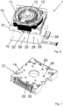
- Fig. 1 shows an overall view of the door drive 100, how it can be installed in a building, which should also include installation on ships and airplanes, and a door drive 100 of this type serves, for example, as a drive for an automatic sliding door system.
- the basic structure of the door drive 100 forms a support profile 34, which is shown shortened for easier viewing.
- the essential upper part of the L-shaped support profile 34 is shown cut away in order to make the other essential components of the door drive 100 visible.
- the door drive 100 has a motor unit 1 as a central component, and the motor unit 1 has the basic shape of a cuboid, which forms the housing 10 of the motor unit 1.
- a pulley 35 is arranged on the motor unit 1, over which a toothed belt can be placed, with which the connection to the wing element or elements, for example the glass sliding elements, is ultimately established , will be produced.
- the door drive 100 Adjacent to the motor unit 1, the door drive 100 has a power supply 36 and a controller 37, and the power supply 36 and the controller 37 are arranged on opposite sides of the motor unit 1.
- the motor unit 1 has side surfaces 32, via which the motor unit 1 is held on the support profile 34 by means of flange elements 33.
- the motor unit 1 is attached to the support profile 34 with a first flange element 33, the first flange element 33 also receiving the power supply 36. Furthermore, the motor unit 1 is connected to the support profile 34 with a second flange element 33, the second flange element 33 also receiving the control 37.
- Fig. 2 shows a perspective view of the isolated motor unit 1 with a housing 10, and outside the housing 10, the pulley 35 for coupling a is located on the top side of the illustration Toothed belt above the housing 10.
- the housing 10 of the motor unit 1 has a first upper housing half 20 and a second lower housing half 21, the housing halves 20, 21 being designed in the same way as one another, but do not have to be designed in the same way within the scope of the invention.
- the cuboid is determined by the longitudinal edge 17, the width edge 18 and the height edge 19, the side surfaces 32 being spanned by the width edge 18 and the height edge 19.
- the front side surface, which is spanned by the longitudinal edge 17 and the height edge 19, has a window-shaped recess 38, from which a surface section of the stator 11 protrudes.
- the outward-facing surface section of the stator 11 serves for heat-transferring contact with another body, for example with the carrier profile 34 or with another, separate heat sink.
- circuit board 15 is used to electrically contact the windings that are applied to the stator 11.
- connections on the circuit board which are shown as a winding connection 39 and a Hall sensor connection 40, in particular for connection to the control of the door drive.
- Fig. 3 shows the motor unit in a perspective from the bottom, so that the outer surface 14, which is arranged opposite the pulley 35 on the housing 10, is visible.
- the circuit board 15 is shown at a distance from the actual position so that the outer surface 14 becomes visible.
- the outer surface 14 is located on the outside of the lower housing half 21, which is connected to the housing half 20.
- Openings 23 are made in the outer surface 14 of the housing half 21, from which the contact elements 22 protrude for contacting the circuit board, and the circuit card 14 is held in arrangement on the housing 10 via the contact elements 22.
- openings 29 are made in the outer surface, through which Hall sensors on the circuit board 15, which are not visible in the illustration, can sense the position and movement of the permanent magnets of the rotor of the motor unit 1.
- Fig. 4 shows a detailed view of the contact elements 22, which are pressed into formations 24, and the formations 24 are located on the winding carrier 31 of the stator 11.
- the stator 11 is shown with the sheet metal lamina pack, and the winding carrier 31 is formed by a plastic injection molded component.
- the metallic contact elements 22 can cut into the front or end sides of the formations 24 of the winding carrier 31 by being pressed into them in such a way that the contact elements 22 are firmly connected to the formations 24 and at the same time contact the winding wire of the coils of the stator. If the circuit board 15 is attached, the contact elements 22 reach the mandrel section 27 through the holes in the circuit board 15, and the circuit board 15 is in a firmly held arrangement on the housing 10 of the motor unit.
- Fig. 5 shows in perspective a contact element 22 with the cutting section 25 with the opposite mandrel section 27.
- the cutting section 25 has a cutting opening through which the winding wire passes when the contact element 22 is pressed into the end side of the formations 24 on the stator 11. For this purpose, the winding wire is previously inserted into the slots of the formations 24.
- Fig. 6 shows a further view of the circuit board 15 below the partially shown housing 10, and the housing 10 is only shown with the lower housing half 21, so that the stator 11 with the rotor 12 becomes visible, the rotor 12 being mounted on the output shaft 13 and in the housing 10 is rotatable.
- the Hall sensors 28 can be seen, of which, for example, six are arranged evenly distributed over a smaller radius.
- the holes 26 for passing the contact elements 22 through are arranged on the circuit board 15 over a larger radius.
- Fig. 7 shows a perspective view of the housing half 21 with the outer surface 14, and the openings 23 and the openings 29 are made in the outer surface 14 and thus also in the housing half 21.
- the formations of the winding support can extend through the openings 23 and thus protrude to a degree above the outer surface 14, so that the circuit board 15 can ultimately rest on the end faces of the formations.
- the openings 29 are positioned so that their position corresponds to the Hall sensors 28 on the circuit board 15.
- Fig. 8 finally shows a perspective view of a stator 11 with a total of twelve coils, which are wound on tongues 41 projecting radially inwards.
- the winding carrier 31 has been injected around the sheet metal lamina pack 42 using the plastic injection molding process, on which the windings are finally wound.
- Each coil on a separate tongue 41 is assigned a molding 24, to which one end of the winding wire 16 is brought. The further end of the winding wire can be continued to the adjacent coil to form coil pairs.
- the contact elements 22 (not shown) are pressed through the slots in the formations 24 so that they contact the winding wire 16.
- the holding projections 43, on which the winding wire 16 is wound endlessly in order to be guided to the next coil, are sheared off before the stator 11 is put into operation, so that the winding wire is also separated after contacting the contact element 22.
Description
- Die Erfindung betrifft einen Türantrieb zur Anordnung an oder in Verbindung mit einer Türanlage, mit dem zumindest ein Flügelelement der Türanlage bewegbar ist, aufweisend eine Motoreinheit mit einem Gehäuse, in dem ein Stator ruhend aufgenommen ist und wobei ein Rotor drehbeweglich im Gehäuse angeordnet ist, der eine Abtriebswelle aufweist, wobei die Abtriebswelle mit dem Flügelelement antreibend in Wirkverbindung gebracht werden kann. Weiterhin betrifft die Erfindung eine Türanlage mit einem solchen Türantrieb, aufweisend wenigstens ein Flügelelement, mit dem der Türantrieb antreibend in Wirkverbindung steht.
- Aus der
DE 10 2008 046 062 A1 ist ein Türantrieb zur Anordnung an einer Türanlage bekannt, und der Antrieb dient zur Bewegung von Flügelelementen der Türanlage, die als automatische Schiebetür ausgebildet ist. Der Türantrieb weist hierfür eine Motoreinheit mit einem Gehäuse auf, und an das Gehäuse der Motoreinheit ist eine Getriebeeinheit angebracht, die als Schneckenradgetriebe ausgeführt ist. Damit ist die Motoreinheit als schnelldrehender Motor konzipiert, und mit der Getriebeeinheit wird die höhere Drehzahl des Rotors der Motoreinheit reduziert auf eine geringere Drehzahl zum Antrieb einer Riemenscheibe, die auf eine Abtriebswelle der Getriebeeinheit aufgesetzt ist. - Über die Riemenscheibe wird ein Zahnriemen gelegt, der mit den Flügelelementen der automatischen Schiebetür verbunden wird. Da die Motoreinheit schnelldrehend ausgelegt ist, und die Drehzahl auf die Riemenscheibe reduziert werden muss, ist in Verbindung mit dem Motor die Getriebeeinheit notwendig, wodurch zusätzlicher Bauraum erforderlich wird, und wodurch die Konstruktion des Türantriebs komplexer wird. Die räumliche Dimensionierung des Türantriebs muss an die Notwendigkeit der Getriebeeinheit angepasst werden, und da der Motor eine zylinderförmige Grundform aufweist, nimmt dieser einen Bauraum ein, der in Bezug auf seine Einbauumgebung keine optimale Raumnutzung ermöglicht. Gleiches gilt für ein Schneckenradgetriebe, das insbesondere in Verbindung mit dem Motor quer verläuft und folglich sehr bauraum intensiv ist.
- Insbesondere dann, wenn die Abtriebswelle zur direkten Aufnahme einer Riemenscheibe in der eingebauten Türanlage horizontal verlaufen soll, muss die Motorbauform vor allem in Erstreckungsrichtung der Abtriebswelle kurz ausfallen, da es sonst zu Bauraumproblemen im Einbau der Motoreinheit kommt. Dies liegt darin begründet, dass der mit einem Zahnriemen über die Riemenscheibe angetriebene Läufer im Trägerprofil, der zur Aufnahme eines Flügelelementes beispielsweise einer automatischen Schiebetür dient, noch innerhalb des Trägerprofils an der Riemenscheibe vorbeilaufen können muss. Daher sollte die Motoreinheit in Erstreckungsrichtung der Rotorachse möglichst kurzbauend ausfallen.
- Einen weiteren Türantrieb offenbart die
DE 10 2014 115 932 A1 , und der Türantrieb weist als Grundkörper einen einteiligen quaderförmigen Körper auf, in den Aussparungen zur Aufnahme einer Motoreinheit und einer Getriebestufe eingebracht sind. Zur weiteren Aufnahme einer Steuerung, einem Netzteil und dergleichen sind in dem Block weitere Aussparungen und Öffnungen vorgesehen. Der quaderförmige Körper bildet also ein Gehäuse als Träger der einzelnen Komponenten des Türantriebes und ist über der gesamten Abmessung des Antriebes einteilig und gewissermaßen monolithisch ausgeführt. Im quaderförmigen Körper selbst muss zudem eine elektrische Einrichtung zur Beschaltung der Statorwicklungen eingerichtet sein, wodurch sich die Baugröße nachteilhafterweise wieder erhöht. Zum technischen Umfeld wird weiterhin auf dieEP 3 015 632 A1 und dieEP 3 016 247 A1 verwiesen. - Grundsätzlich wird bei der Konstruktion von Türantrieben zur Anordnung an oder in Verbindung mit einer Türanlage das Ziel verfolgt, den Türantrieb möglichst kompakt und mit kleinen Abmessungen auszuführen, beispielsweise indem eine Getriebeeinheit oder eine Getriebestufe innerhalb des Türantriebs bereits vermieden wird. Türantriebe werden üblicherweise oberhalb der linear bewegbaren Flügelelemente einer automatischen Schiebetüranlage angeordnet und weisen ein Trägerprofil auf, das einen Grundkörper der Türanlage bildet und am Trägerprofil werden der Türantrieb integriert montiert und gleichermaßen die Flügelelemente linear geführt. Als Verbindungsmittel zwischen dem Türantrieb und den Flügelelementen dient in der Regel ein Zahnriemen, wobei auch andere Zugmittel wie Kettenverbindungen und dergleichen möglich sind. Der Türantrieb bildet dabei mit wenigstens dem Motor, einem Netzteil und einer Steuerung eine eigene Baueinheit, die mit der Anordnung am Trägerprofil in die Türanlage integriert wird.
- Ist die Motoreinheit als langsam drehender Motor mit direkt auf der Abtriebswelle aufgebrachter Riemenscheibe konzipiert, also als sogenannter Langsamläufer, so ist ein solcher Motor in der Regel als ein elektronisch kommutierter Torque-Motor ausgeführt. Derartige Motoren weisen eine Vielzahl von Wicklungen auf, die auf jeweiligen meistens radial nach innen weisenden Zähnen eines Stators aufgebracht sind, wenn der Motor als Innenläufer ausgeführt ist, bei dem sich der Rotor innerhalb des Stators befindet und rotieren kann, während der Stator ruhend im Gehäuse der Motoreinheit aufgenommen ist und eine entsprechende elektrische Beschaltung der Wicklungen erfordert.
- Aufgabe der Erfindung ist die Schaffung eines Türantriebs mit einer Motoreinheit, die eine hohe Integrationsdichte und eine hohe Leistungsdichte aufweist, und wobei der Motor in Verbindung mit dem wenigstens einen Flügelelement als Direktantrieb ausgeführt sein soll. Zur hohen Integrationsdichte und Leistungsdichte soll eine vorteilhafte Anordnung und Ausführung der elektrischen Beschaltung der Wicklungen des Stators beitragen.
- Diese Aufgabe wird ausgehend von einem Türantrieb gemäß Anspruch 1 und ausgehend von einer Türanlage gemäß Anspruch 15 mit den jeweils kennzeichnenden Merkmalen gelöst. Vorteilhafte Weiterbildungen der Erfindung sind in den abhängigen Ansprüchen und in der Beschreibung angegeben.
- Die Erfindung schließt die technische Lehre ein, dass das Gehäuse der Motoreinheit eine Außenfläche aufweist, an der eine Leiterkarte angeordnet ist, die mit einem Wicklungsdraht des Stators elektrisch verbunden ist.
- Kerngedanke der Erfindung ist eine Anordnung der Leiterkarte unmittelbar angrenzend oder mit einem sehr geringen Abstand zu einer Außenfläche des Gehäuses und damit eine Anordnung im Verbund mit der Motoreinheit, sodass die Wicklungen des Stators unmittelbar mit der Leiterkarte verbunden werden können. Die unmittelbare Verbindung betrifft dabei insbesondere eine kabellose Verbindung, und die Wicklungen des Stators können über die Leiterkarte entsprechend beschaltet werden. Die direkte Anordnung der Leiterkarte an die Außenfläche des Gehäuses vergrößert die Bauhöhe der Motoreinheit nicht wesentlich, und es ergibt sich ein deutlich leichterer Aufbau der Motoreinheit, da innerhalb des Gehäuses keine Kabel verlegt werden müssen, um den Wicklungsdraht der Wicklungen auf dem Stator zu kontaktieren, und die Kontakte nach außen zu führen. Die elektrische Verbindung des Wicklungsdrahtes mit der Leiterkarte erfolgt kabellos oder sogar drahtlos, indem starre Steckverbindungen genutzt werden, die sich zwischen dem Stator und der Leiterkarte erstrecken und unmittelbar mit dem Wicklungsdraht kontaktiert sind.
- Erfindungsgemäß weist das Gehäuse der Motoreinheit die Form eines Quaders auf. Vorteilhafterweise kann der Quader eine Längskante, eine Breitenkante und eine Höhenkante aufweisen, wobei die Längskante größer ist als die Breitenkante, und/oder wobei die Breitenkante größer ist als die Höhenkante. Die Außenfläche des Gehäuses, an der die Leiterkarte angeordnet ist, wird insbesondere mit einer mit der Längskante und mit der Breitenkante aufgespannten Ebene gebildet.
- Ein Quader im vorliegenden Sinn ist ein Körper, der von sechs Rechteckflächen begrenzt wird, wobei die Rechteckflächen im Wesentlichen, aber nicht vollständig, plan sein sollten, also durchaus Anformungen, Wölbungen, Schrägungen, Rippen und dergleichen aufweisen können. Insofern ist im Sinne der Erfindung die Quaderform der Motoreinheit allenfalls annähernd mathematisch zu verstehen, ein Rechteckkörper mit leichten Winkelabweichungen und Formabweichungen fällt damit auch noch unter den Begriff des Quaders, ohne also am mathematischen Begriff des Quaders zu haften, beispielsweise, wenn die Außenseite des Gehäuses Rippen, Anformungen, Schraubbohrungen und dergleichen aufweisen.
- Das Gehäuse ist jedoch im Wesentlichen mit Planflächen begrenzt, sodass nur die Grundform der Motoreinheit einen Quader bildet, und es kann die Grundform auch als eine quaderförmige Hüllform zu verstehen sein, ohne dass das Gehäuse der Motoreinheit die quaderförmige Hüllform exakt abbildet.
- Erfindungsgemäß ist das Gehäuse der Motoreinheit mittels wenigstens mittelbar miteinander verbundener Gehäusehälften gebildet, zwischen denen der Stator und der Rotor aufgenommen sind, wobei vorteilhafterweise die Außenfläche, an der die Leiterkarte angeordnet ist, eine der Abtriebswelle abgewandte Rückseite der Motoreinheit bildet. Die Gehäusehälften können halbschalenförmig ausgeführt sein, und werden die Gehäusehälften miteinander verbunden, vervollständigt sich der so gebildete Gehäusekörper zu einem Quader. Die Gehäusehälften müssen dabei nicht zwingend eine exakte Hälfte des gesamten Gehäuses bilden, und die Teilungsebene zwischen den Gehäusehälften muss nicht auf einer halben Höhe einer Höhenkante des Quaders liegen. Insofern können auch Gehäusehälften vorgesehen sein, die unterschiedlich bemaßt, gestaltet und dimensioniert sind, diese können jedoch in einer Weise aufeinander gebracht verbunden werden, dass der Quader zur Bildung des Gehäuses entsteht, und so die Grundform der Motoreinheit gebildet wird. Es können insbesondere zwei Gehäusehälften vorgesehen sein.
- Um den Wicklungsdraht des Stators mit Kontakten auf der Leiterkarte zu kontaktieren, befinden sich mit weiterem Vorteil am Stator elektrische Kontaktelemente, an denen die Leiterkarte haltend angeordnet ist. Damit dienen die Kontaktelemente sowohl der elektrischen Kontaktierung des Wicklungsdrahtes mit der Leiterkarte als auch zur haltenden Aufnahme der Leiterkarte an der Motoreinheit. Hierfür weist das Gehäuse der Motoreinheit Durchbrüche auf, durch die hindurch sich die elektrischen Kontaktelemente erstrecken. Auch kann der Stator hervorstehende Anformungen aufweisen, an denen die elektrischen Kontaktelemente aufgenommen sind, die mit dem Wicklungsdraht des Stators elektrisch kontaktiert sind. Der Stator weist neben einem Blechlamellenpaket einen Wicklungsträger auf, der als Spritzgussbauteil so ausgeführt ist, dass der Wicklungsträger das Blechlamellenpaket wenigstens abschnittsweise umschließt. Am Wicklungsträger können die Anformungen ausgebildet sein, an denen die elektrischen Kontaktelemente aufgenommen sind, und die Anformungen erstrecken sich durch die Durchbrüche im Gehäuse der Motoreinheit hindurch und stehen aus der Oberfläche des Gehäuses leicht hervor, sodass die Leiterkarte auf den Stirnflächen der Anformungen anliegen kann, wenn die Leiterkarte mit den Kontaktelementen am Gehäuse der Motoreinheit gehalten wird. So wird die Leiterkarte beispielsweise mit einem Abstand von 0,2 mm bis 5 mm, bevorzugt von 0,5 mm bis 3 mm noch weiter bevorzugt von 1 mm bis 2 mm außenseitig am Gehäuse angeordnet.
- Die Kontaktelemente weisen gemäß einer weiteren vorteilhaften Ausführungsform einen Schneidabschnitt auf, der in den Wicklungsdraht einschneidet und diesen elektrisch kontaktiert. Der Wicklungsdraht wird hierfür in schlitzförmige Vertiefungen der Anformungen eingelegt, und anschließend wird das Kontaktelement in die Anformungen eingepresst. Dabei schneidet sich der Schneidabschnitt des Kontaktelementes derart in den Wicklungsdraht ein, dass dieser nicht durchtrennt wird, sondern der Wicklungsdraht erfährt eine sichere elektrische Kontaktierung mit dem Kontaktelement.
- Weiterhin ist vorteilhafterweise vorgesehen, dass die Leiterkarte Löcher aufweist, in denen ein Dornabschnitt der Kontaktelemente eingepresst ist, wodurch die Leiterkarte am Stator und damit an der Motoreinheit fest aufgenommen ist. Die Löcher in der Leiterkarte sind zur elektrischen Kontaktierung der Kontaktelemente wenigstens innenseitig mit einer metallischen Oberfläche ausgestattet, in die sich der Dornabschnitt der Kontaktelemente leicht einschneidet, und wobei sich an die metallische Oberfläche in den Löchern eine Leiterbahn anschließt, die schließlich elektrisch kontaktiert ist mit dem Dornabschnitt und damit auch mit dem Kontaktelement. Der Dornabschnitt und der Schneidabschnitt können sich am Kontaktelement jeweils gegenüberliegend befinden. Die Löcher in der Leiterkarte sind komplementär zur Anordnung der Kontaktelemente ausgebildet, sodass die Leiterkarte passgenau auf die Kontaktelemente aufgesteckt werden kann, wobei beispielsweise zwölf Kontaktelemente vorgesehen sind, sodass auch zwölf Löcher in der Leiterkarte eingebracht sind.
- Auf der Seite der Leiterkarte, die zur Außenfläche des Gehäuses hin weist, sind mit weiterem Vorteil Hallsensoren angeordnet, wobei in das Gehäuse Öffnungen eingebracht sind, die komplementär zu den Positionen der Hallsensoren ausgebildet sind. Der Stator weist Permanentmagnete auf, wobei die Hallsensoren und die Öffnungen auf einem Radius um die Abtriebswelle herum so angeordnet sind, dass die Permanentmagnete bei Rotation des Rotors relativ zu den Hallsensoren unter magnetischer Beeinflussung derselben bewegt werden. Der Radius, auf dem die Hallsensoren um die Abtriebswelle herum angeordnet sind, kann leicht größer oder kleiner sein als der Radius der Permanentmagnete in Anordnung am Rotor. Erst durch diesen radialen Versatz der Hallsensoren relativ zur Rotationsbahn der Permanentmagnete können die Hallsensoren mit den Permanentmagneten derart wechselwirken, dass die Hallsensoren eine entsprechende Information über den Rotationszustand des Rotors abgeben können, beispielsweise betreffend die Rotationsposition und die Drehzahl des Rotors.
- An der Leiterkarte befinden sich Anschlüsse, sodass die Hallsensoren und die Wicklungsdrähte mit einer weiteren, externen Steuerung zur Ansteuerung des Motors verbunden werden können, insbesondere ein Wicklungsanschluss und ein Hallgeberanschluss.
- Die Leiterkarte weist erfindungsgemäß eine Rechteckform auf, die der Rechteckform der Außenfläche des Gehäuses entspricht, an der die Leiterkarte angeordnet ist. Insbesondere kann die Leiterkarte derart bemaßt sein, dass diese mit den Maßen der Längskante und der Breitenkante des Gehäuses der Motoreinheit übereinstimmt.
- Die Erfindung betrifft weiterhin eine Türanlage mit einem Türantrieb mit den vorstehend beschriebenen Merkmalen. Die Türanlage kann ein Verbindungselement zum Verbinden mit einem Flügelelement aufweisen. Zusätzlich oder alternativ kann die Türanlage wenigstens ein Flügelelement, mit dem der Türantrieb antreibend in Wirkverbindung steht, aufweisen. Beispielsweise kann die Türanlage als eine Schiebetüranlage ausgebildet sein. Die Schiebetüranlage kann einen Riemen, insbesondere einen Zahnriemen, umfassen. Das Verbindungselement kann zumindest mittelbar mit dem Riemen verbunden sein. Das Verbindungselement kann als Läufer, insbesondere als Rollwagen, ausgebildet sein. Das Verbindungselement kann in einer Schiene, insbesondere in einer Schiene des Trägerprofils, laufen. Der Riemen kann zwischen Riemenscheiben der Türanlage gespannt sein. Eine der Riemenscheiben kann als die Riemenscheibe des erfindungsgemäßen Türantriebs ausgebildet sein.
- Weitere, die Erfindung verbessernde Maßnahmen werden nachstehend gemeinsam mit der Beschreibung eines bevorzugten Ausführungsbeispiels der Erfindung anhand der Figuren näher dargestellt. Es zeigt:
- Fig. 1
- eine Gesamtansicht des Türantriebs mit einer Motoreinheit,
- Fig. 2
- eine perspektivische Ansicht der Motoreinheit mit einer unterseitig angeordneten Leiterkarte,
- Fig. 3
- die Ansicht der Motoreinheit von der Unterseite mit einer abgerückt gezeigten Leiterkarte,
- Fig. 4
- eine ausschnittsweise Detailansicht des Stators mit Kontaktelementen zwischen einem Wicklungsträger des Stators und der Leiterkarte,
- Fig. 5
- eine perspektivische Ansicht eines Kontaktelementes,
- Fig. 6
- eine perspektivische Ansicht der Motoreinheit mit einer entnommenen oberen Gehäusehälfte,
- Fig. 7
- eine perspektivische Ansicht der oberen Gehäusehälfte und
- Fig. 8
- eine perspektivische Ansicht des Stators mit mehreren Wicklungen aus Wicklungsdraht.
-
Fig. 1 zeigt eine Gesamtansicht des Türantriebs 100, wie dieser in einem Gebäude installiert werden kann, womit auch die Installation auf Schiffen und in Flugzeugen umfasst sein soll, und ein Türantrieb 100 dieser Art dient beispielsweise als Antrieb für eine automatische Schiebetüranlage. Die Grundstruktur des Türantriebs 100 bildet ein Trägerprofil 34, welches zur einfacheren Ansicht verkürzt dargestellt ist, zudem ist der wesentliche obere Teil des L-förmigen Trägerprofils 34 aufgeschnitten gezeigt, um die weiteren vorliegend wesentlichen Komponenten des Türantriebs 100 sichtbar zu machen. - Als zentraler Bestandteil weist der Türantrieb 100 eine Motoreinheit 1 auf, und die Motoreinheit 1 besitzt die Grundform eines Quaders, der das Gehäuse 10 der Motoreinheit 1 bildet. Um einen Abtrieb und damit eine Verbindung zu einem nicht näher dargestellten Flügelelement einer Türanlage zu ermöglichen, ist an der Motoreinheit 1 eine Riemenscheibe 35 angeordnet, über die ein Zahnriemen gelegt werden kann, mit dem schließlich die Verbindung zu dem oder den Flügelelementen, beispielsweise den Glasschiebeelementen, hergestellt wird.
- Benachbart zur Motoreinheit 1 weist der Türantrieb 100 ein Netzteil 36 und eine Steuerung 37 auf, und das Netzteil 36 und die Steuerung 37 sind an sich gegenüberliegenden Seiten der Motoreinheit 1 angeordnet. Hierzu weist die Motoreinheit 1 Seitenflächen 32 auf, über die die Motoreinheit 1 mittels Flanschelementen 33 am Trägerprofil 34 haltend aufgenommen ist.
- Die Motoreinheit 1 ist mit einem ersten Flanschelement 33 am Trägerprofil 34 befestigt, wobei das erste Flanschelement 33 zugleich das Netzteil 36 mit aufnimmt. Weiterhin ist die Motoreinheit 1 mit einem zweiten Flanschelement 33 mit dem Trägerprofil 34 verbunden, wobei das zweite Flanschelement 33 zugleich die Steuerung 37 aufnimmt. Alternativ ist auch die Ausführung eines einzigen Flansches möglich, um wenigstens die Motoreinheit 1, das Netzteil 36 und die Steuerung 37 aufzunehmen, ferner besteht die Möglichkeit, dass die Motoreinheit1, das Netzteil 36 und/oder die Steuerung 37 jeweils zugeordnete separate Flanschelemente zur Anordnung im oder am Trägerprofil 34 aufweisen.
-
Fig. 2 zeigt eine perspektivische Ansicht der vereinzelten Motoreinheit 1 mit einem Gehäuse 10, und außerhalb des Gehäuses 10 befindet sich in der Darstellung oberseitig die Riemenscheibe 35 zur Ankopplung eines Zahnriemens oberhalb des Gehäuses 10. Das Gehäuse 10 der Motoreinheit 1 weist eine erste obere Gehäusehälfte 20 und eine zweite untere Gehäusehälfte 21 auf, wobei die Gehäusehälften 20, 21 beispielhaft zueinander gleichartig ausgeführt sind, im Rahmen der Erfindung aber nicht gleichartig ausgeführt sein müssen. - Der Quader ist bestimmt durch die Längskante 17, die Breitenkante 18 und die Höhenkante 19, wobei die Seitenflächen 32 aufgespannt werden durch die Breitenkante 18 und die Höhenkante 19. Die vordere Seitenfläche, die durch die Längskante 17 und die Höhenkante 19 aufgespannt wird, weist eine fensterförmige Aussparung 38 auf, aus der ein Flächenabschnitt des Stators 11 herausragt. Der nach außen weisende Flächenabschnitt des Stators 11 dient zum wärmeübertragenden Kontakt mit einem weiteren Körper, beispielsweise mit dem Trägerprofil 34 oder mit einem weiteren, separaten Kühlkörper. Dadurch kann trotz des im Wesentlichen geschlossen ausgeführten Gehäuses 10 mit der oberen und unteren Gehäusehälfte 20, 21 der Stator 11 in direkten wärmeübertragenden Kontakt mit einem Motorumbauteil gebracht werden.
- Auf der der Riemenscheibe 35 gegenüberliegenden unteren Seite befindet sich eine Außenfläche 14 des Gehäuses 10, an die mit einem leichten Abstand zu dieser Außenfläche 14 eine Leiterkarte 15 angeordnet ist. Die Leiterkarte 15 dient zur elektrischen Kontaktierung der Wicklungen, die auf dem Stator 11 aufgebracht sind. Um die Motoreinheit 1 mit der Steuerung des Türantriebs zu verbinden, befinden sich auf der Leiterkarte 15 Anschlüsse, die gezeigt sind als ein Wicklungsanschluss 39 und ein Hallgeberanschluss 40, insbesondere zur Verbindung mit der Steuerung des Türantriebs.
-
Fig. 3 zeigt die Motoreinheit in einer Perspektive von der Unterseite, sodass die Außenfläche 14, die der Riemenscheibe 35 gegenüberliegend am Gehäuse 10 angeordnet ist, sichtbar ist. Die Leiterkarte 15 ist beabstandet von der eigentlichen Position gezeigt, sodass die Außenfläche 14 sichtbar wird. Die Außenfläche 14 befindet sich außenseitig an der unteren Gehäusehälfte 21, die mit der Gehäusehälfte 20 verbunden ist. - In der Außenfläche 14 der Gehäusehälfte 21 sind Durchbrüche 23 eingebracht, aus denen die Kontaktelemente 22 zur Kontaktierung der Leiterkarte hervorstehen, und die Leiterkarte 14 wird in Anordnung am Gehäuse 10 über die Kontaktelemente 22 gehalten. Hierfür befinden sich Löcher 26 in der Leiterkarte 15, in die die Kontaktelemente 22 eingedrückt werden, wenn die Leiterkarte 15 angrenzend an die Außenfläche 14 angeordnet wird.
- Weiterhin sind in der Außenfläche 14 Öffnungen 29 eingebracht, durch die in der Abbildung nicht sichtbare Hallsensoren auf der Leiterkarte 15 die Position und Bewegung der Permanentmagnete des Rotors der Motoreinheit 1 sensieren können.
-
Fig. 4 zeigt eine Detailansicht der Kontaktelemente 22, die in Anformungen 24 eingepresst sind, und die Anformungen 24 befinden sich am Wicklungsträger 31 des Stators 11. Der Stator 11 ist mit dem Blechlamellenpaket gezeigt, und der Wicklungsträger 31 ist durch ein Kunststoff-Spritzgussbauteil gebildet. Die metallischen Kontaktelemente 22 können sich durch das Einpressen in die Stirn- oder Endseiten der Anformungen 24 des Wicklungsträgers 31 so in diese einschneiden, dass die Kontaktelemente 22 fest mit den Anformungen 24 verbunden sind und zugleich den Wicklungsdraht der Spulen des Stators kontaktieren. Wird die Leiterkarte 15 angebracht, so gelangen die Kontaktelemente 22 mit dem Dornabschnitt 27 durch die Löcher in der Leiterkarte 15, und die Leiterkarte 15 befindet sich in fest gehaltener Anordnung am Gehäuse 10 der Motoreinheit. -
Fig. 5 zeigt perspektivisch ein Kontaktelement 22 mit dem Schneidabschnitt 25 mit dem gegenüberliegenden Dornabschnitt 27. Der Schneidabschnitt 25 weist eine Schneidöffnung auf, durch die der Wicklungsdraht gelangt, wenn das Kontaktelement 22 in die Endseite der Anformungen 24 am Stator 11 eingepresst wird. Hierzu wird zuvor der Wicklungsdraht in die Schlitze der Anformungen 24 eingelegt. -
Fig. 6 zeigt eine weitere Ansicht der Leiterkarte 15 unterhalb des teilweise dargestellten Gehäuses 10, und das Gehäuse 10 ist lediglich mit der unteren Gehäusehälfte 21 gezeigt, sodass der Stator 11 mit dem Rotor 12 sichtbar wird, wobei der Rotor 12 auf der Abtriebswelle 13 aufgebracht und im Gehäuse 10 rotierbar ist. Mit Blick auf die Leiterkarte 15 sind die Hallsensoren 28 erkennbar, von denen beispielsweise sechs Stück auf einem kleineren Radius gleichmäßig verteilt angeordnet sind. Die Löcher 26 zum Hindurchführen der Kontaktelemente 22 sind auf einem größeren Radius auf der Leiterkarte 15 angeordnet. -
Fig. 7 zeigt in einer perspektivischen Ansicht die Gehäusehälfte 21 mit der Außenfläche 14, und in der Außenfläche 14 und damit auch in der Gehäusehälfte 21 sind die Durchbrüche 23 und die Öffnungen 29 eingebracht. Durch die Durchbrüche 23 können sich die Anformungen des Wicklungsträgers hindurch erstrecken und so mit einem Maß über der Außenfläche 14 hervorstehen, sodass die Leiterkarte 15 schließlich auf den Stirnflächen der Anformungen aufliegen kann. Die Öffnungen 29 sind so positioniert, dass diese mit den Hallsensoren 28 auf der Leiterkarte 15 in ihrer Position korrespondieren. -
Fig. 8 zeigt schließlich eine perspektivische Ansicht eines Stators 11 mit insgesamt zwölf Spulen, die auf radial nach innen ragende Zungen 41 aufgewickelt sind. Um das Blechlamellenpaket 42 herum ist der Wicklungsträger 31 im Kunststoff-Spritzgussverfahren gespritzt worden, auf dem schließlich die Wicklungen aufgewickelt sind. Jeder Spule auf einer separaten Zungen 41 ist eine Anformung 24 zugeordnet, an die ein Ende des Wicklungsdrahtes 16 herangeführt wird. Das weitere Ende des Wicklungsdrahtes kann dabei zur benachbarten Spule weitergeführt werden, um Spulenpaare zu bilden. - Die nicht dargestellten Kontaktelemente 22 werden nach Hineinführung des Wicklungsdrahtes durch die Schlitze in den Anformungen 24 eingepresst, sodass diese den Wicklungsdraht 16 kontaktieren. Die Haltevorsprünge 43, auf denen der Wicklungsdraht 16 endlos aufgewickelt ist, um zur nächsten Spule geführt zu werden, werden vor Inbetriebnahme des Stators 11 abgeschert, sodass auch der Wicklungsdraht nach Kontaktierung mit dem Kontaktelement 22 getrennt wird.
- Die Erfindung beschränkt sich in ihrer Ausführung nicht auf das vorstehend angegebene Ausführungsbeispiel. Der Schutzumfang wird durch die beiliegenden Ansprüche definiert.
-
- 100
- Türantrieb
- 1
- Motoreinheit
- 10
- Gehäuse
- 11
- Stator
- 12
- Rotor
- 13
- Abtriebswelle
- 14
- Außenfläche
- 15
- Leiterkarte
- 16
- Wicklungsdraht
- 17
- Längskante
- 18
- Breitenkante
- 19
- Höhenkante
- 20
- Gehäusehälfte
- 21
- Gehäusehälfte
- 22
- Kontaktelement
- 23
- Durchbruch
- 24
- Anformung
- 25
- Schneidabschnitt
- 26
- Loch
- 27
- Dornabschnitt
- 28
- Hallsensor
- 29
- Öffnung
- 30
- Permanentmagnet
- 31
- Wicklungsträger
- 32
- Seitenfläche
- 33
- Flanschelement
- 34
- Trägerprofil
- 35
- Riemenscheibe
- 36
- Netzteil
- 37
- Steuerung
- 38
- fensterförmige Aussparung
- 39
- Wicklungsanschluss
- 40
- Hallgeberanschluss
- 41
- Zunge
- 42
- Blechlamellenpaket
- 43
- Haltevorsprung
Claims (14)
- Türantrieb (100) zur Anordnung an oder in Verbindung mit einer Türanlage, mit dem zumindest ein Flügelelement der Türanlage bewegbar ist, aufweisend eine Motoreinheit (1) mit einem Gehäuse (10), in dem ein Stator (11) ruhend aufgenommen ist und wobei ein Rotor (12) drehbeweglich im Gehäuse (10) angeordnet ist, der eine Abtriebswelle (13) aufweist, wobei die Abtriebswelle (13) mit dem Flügelelement antreibend in Wirkverbindung bringbar ist, wobei der Türantrieb (100) eine Leiterkarte (15) aufweist, die mit einem Wicklungsdraht (16) des Stators (11) elektrisch verbunden ist, dadurch gekennzeichnet, dass das Gehäuse (10) der Motoreinheit (1) mittels miteinander verbundener Gehäusehälften (20, 21) gebildet ist, zwischen denen der Stator (11) und der Rotor (12) aufgenommen sind und wobei das Gehäuse (10) der Motoreinheit (1) die Form eines Quaders aufweist und eine Außenfläche (14) aufweist, an der die Leiterkarte (15) angeordnet ist, wobei die Leiterkarte (15) eine Rechteckform aufweist, die der Rechteckform der Außenfläche (14) des Gehäuses (10) entspricht.
- Türantrieb (100) nach Anspruch 1, dadurch gekennzeichnet, dass der Quader eine Längskante (17), eine Breitenkante (18) und eine Höhenkante (19) aufweist, wobei die Längskante (17) größer ist als die Breitenkante (18) und/oder wobei die Breitenkante (18) größer ist als die Höhenkante (19) und/oder wobei die Außenfläche (14) mit einer mit der Längskante (17) und der Breitenkante (18) aufgespannten Ebene gebildet ist.
- Türantrieb (100) nach Anspruch 1 oder 2, dadurch gekennzeichnet, dass die Außenfläche (14), an der die Leiterkarte (15) angeordnet ist, eine der Abtriebswelle (13) abgewandte Rückseite der Motoreinheit (1) bildet.
- Türantrieb (100) nach einem der vorgenannten Ansprüche, dadurch gekennzeichnet, dass der Wicklungsdraht (16) des Stators (11) mit Kontakten auf der Leiterkarte (15) kontaktiert ist, wofür am Stator (11) elektrische Kontaktelemente (22) angeordnet sind, an denen die Leiterkarte (15) haltend angeordnet ist.
- Türantrieb (100) nach Anspruch 4, dadurch gekennzeichnet, dass das Gehäuse (10) der Motoreinheit (1) Durchbrüche (23) aufweist, durch die hindurch sich die elektrischen Kontaktelemente (22) erstrecken.
- Türantrieb (100) nach Anspruch 4 oder 5, dadurch gekennzeichnet, dass der Stator (11) hervorstehende Anformungen (24) aufweist, an denen die elektrischen Kontaktelemente (22) aufgenommen sind, die mit dem Wicklungsdraht (16) des Stators (11) elektrisch kontaktiert sind.
- Türantrieb (100) nach einem der Ansprüche 4 bis 6, dadurch gekennzeichnet, dass die Kontaktelemente (22) einen Schneidabschnitt (25) aufweisen, der in den Wicklungsdraht (16) einschneidet und diesen elektrisch kontaktiert.
- Türantrieb (100) nach einem der Ansprüche 4 bis 7, dadurch gekennzeichnet, dass die Leiterkarte (15) Löcher (26) aufweist, in denen ein Dornabschnitt (27) der Kontaktelemente (22) eingepresst ist und dadurch die Leiterkarte (15) am Stator (11) und damit an der Motoreinheit (1) fest aufnimmt.
- Türantrieb (100) nach einem der vorgenannten Ansprüche, dadurch gekennzeichnet, dass auf der Seite der Leiterkarte (15), die zur Außenfläche (14) des Gehäuses (10) hin weist, Hallsensoren (28) angeordnet sind, wobei in das Gehäuse (10) Öffnungen (29) eingebracht sind, die komplementär zu den Positionen der Hallsensoren (28) ausgebildet sind.
- Türantrieb (100) nach Anspruch 9, dadurch gekennzeichnet, dass der Rotor (11) Permanentmagnete (30) aufweist, wobei die Hallsensoren (28) und die Öffnungen (29) auf einem Radius um die Abtriebswelle (13) herum so angeordnet sind, dass die Permanentmagnete (30) bei Rotation des Rotors (12) relativ zu den Hallsensoren (27) unter magnetischer Beeinflussung derselben bewegt werden.
- Türantrieb (100) nach einem der vorgenannten Ansprüche, dadurch gekennzeichnet, dass der Abstand der Leiterkarte (15) zur Außenfläche (14) des Gehäuses (10) einen Wert von 0,2mm bis 5mm und/oder von 0,5mm bis 3mm und/oder von 1mm bis 2mm aufweist.
- Türantrieb (100) nach einem der Ansprüche 4 bis 8, dadurch gekennzeichnet, dass der Stator (11) einen Wicklungsträger (31) aufweist, an dem die Anformungen (24) ausgebildet sind, wobei die Leiterkarte (15) nach Anordnung an den Kontaktelementen (22) auf den Anformungen (24) aufliegt.
- Türantrieb (100) nach einem der vorgenannten Ansprüche, dadurch gekennzeichnet, dass die Motoreinheit (1) Seitenflächen (32) aufweist, über die die Motoreinheit (1) mittels Flanschelementen (33) an einem Trägerprofil (34) haltend aufgenommen ist.
- Türanlage mit einem Türantrieb (100) gemäß einem der vorgenannten Ansprüche, aufweisend wenigstens ein Verbindungselement zum Verbinden mit einem Flügelelement und/oder wenigstens ein Flügelelement, mit dem der Türantrieb (100) antreibend in Wirkverbindung steht.
Priority Applications (2)
| Application Number | Priority Date | Filing Date | Title |
|---|---|---|---|
| EP19214428.5A EP3835530B1 (de) | 2019-12-09 | 2019-12-09 | Türantrieb mit einer motoreinheit, aufweisend eine vorteilhafte elektrische beschaltung |
| PCT/EP2020/083651 WO2021115802A1 (de) | 2019-12-09 | 2020-11-27 | Türantrieb mit einer motoreinheit, aufweisend eine vorteilhafte elektrische beschaltung |
Applications Claiming Priority (1)
| Application Number | Priority Date | Filing Date | Title |
|---|---|---|---|
| EP19214428.5A EP3835530B1 (de) | 2019-12-09 | 2019-12-09 | Türantrieb mit einer motoreinheit, aufweisend eine vorteilhafte elektrische beschaltung |
Publications (3)
| Publication Number | Publication Date |
|---|---|
| EP3835530A1 EP3835530A1 (de) | 2021-06-16 |
| EP3835530B1 true EP3835530B1 (de) | 2023-11-22 |
| EP3835530C0 EP3835530C0 (de) | 2023-11-22 |
Family
ID=68840904
Family Applications (1)
| Application Number | Title | Priority Date | Filing Date |
|---|---|---|---|
| EP19214428.5A Active EP3835530B1 (de) | 2019-12-09 | 2019-12-09 | Türantrieb mit einer motoreinheit, aufweisend eine vorteilhafte elektrische beschaltung |
Country Status (2)
| Country | Link |
|---|---|
| EP (1) | EP3835530B1 (de) |
| WO (1) | WO2021115802A1 (de) |
Family Cites Families (6)
| Publication number | Priority date | Publication date | Assignee | Title |
|---|---|---|---|---|
| DE102008046062A1 (de) | 2008-09-08 | 2010-03-11 | Dorma Gmbh + Co. Kg | Nachrüstsatz mit einer Antriebseinheit, insbesondere für eine automatische Schiebetür |
| CN103546013A (zh) * | 2010-06-11 | 2014-01-29 | 日本电产伺服有限公司 | 旋转电机 |
| JP6066713B2 (ja) * | 2012-12-19 | 2017-01-25 | ミネベア株式会社 | ステッピングモータ |
| DE102014115929A1 (de) * | 2014-10-31 | 2016-05-19 | Dorma Deutschland Gmbh | Türantrieb |
| DE102014115932A1 (de) | 2014-10-31 | 2016-05-04 | Dorma Deutschland Gmbh | Türantrieb |
| DE102014115921A1 (de) * | 2014-10-31 | 2016-05-04 | Dorma Deutschland Gmbh | Türantrieb |
-
2019
- 2019-12-09 EP EP19214428.5A patent/EP3835530B1/de active Active
-
2020
- 2020-11-27 WO PCT/EP2020/083651 patent/WO2021115802A1/de not_active Ceased
Also Published As
| Publication number | Publication date |
|---|---|
| EP3835530A1 (de) | 2021-06-16 |
| WO2021115802A1 (de) | 2021-06-17 |
| EP3835530C0 (de) | 2023-11-22 |
Similar Documents
| Publication | Publication Date | Title |
|---|---|---|
| EP2584672B1 (de) | Gehäuseteil für eine elektrische Maschine | |
| EP2182616B1 (de) | Bürstenloser Gleichstrommotor | |
| EP0993095B1 (de) | Stator für einen Elektromotor | |
| DE3147418C2 (de) | Isolierstoffteil für Bauteile eines Elektrowerkzeugs | |
| DE102005001705A1 (de) | Verfahren zur Herstellung von Ankern, Verfahren zur Herstellung von Elektromotoren sowie Anker | |
| DE2912802B1 (de) | Anordnung zum Verschalten der Wicklungsenden der Statorwicklung mit einem aeusseren Anschlusskabel in einem Elektro-Kleinmotor,insbesondere einem Aussenlaeufermotor | |
| DE112005000816T5 (de) | Bürstenloser Motor | |
| DE10019512A1 (de) | Motorgehäuse und Poltopf, insbesondere für Fensterheber- oder Schiebedachmotoren | |
| EP3034763B1 (de) | Karusselltür | |
| DE10147225A1 (de) | Antriebseinheit mit einem Elektromotor für Verstelleinrichtungen in Kraftfahrzeugen | |
| EP1648074B1 (de) | Elektrische Maschine, insbesondere Gleichstrommotor | |
| DE10232281A1 (de) | Elektrische Anschlußanordnung | |
| DE112004001898T5 (de) | Kurzschlußteil, Kommutator und Verfahren zur Herstellung eines Kurzschlußteils | |
| WO2004042891A1 (de) | Permanentmagnetmaschine mit axialem luftspal | |
| DE102021100304A1 (de) | Elektromotor mit im Spritzgussverfahren umspritzten Stator | |
| DE212022000093U1 (de) | Aktor | |
| DE102014214909A1 (de) | Anordnung zum Aufnehmen einer Verdrahtung einer elektrischen Maschine, elektrische Maschine und Herstellungsverfahren für eine derartige Verdrahtung | |
| EP3560077B1 (de) | Verfahren zum bewickeln und kontaktieren eines stators sowie stator für einen elektromotor | |
| EP3835530B1 (de) | Türantrieb mit einer motoreinheit, aufweisend eine vorteilhafte elektrische beschaltung | |
| EP2701288B1 (de) | Platine zur Verwendung in einer elektrischen Maschine, insbesondere in einem Elektromotor, vorzugweise einem Außenläufermotor, sowie drehende elektrische Maschine mit einer solchen Platine | |
| DE102021100305A1 (de) | Elektromotor mit im Spritzgussverfahren umspritzten Stator | |
| EP3835528B1 (de) | Türanlage mit einer motoreinheit, aufweisend eine vorteilhafte grundform | |
| EP3035497B1 (de) | Karusselltür | |
| DE10231092A1 (de) | Außenläufermotor | |
| EP3835534B1 (de) | Türantrieb mit einer motoreinheit |
Legal Events
| Date | Code | Title | Description |
|---|---|---|---|
| PUAI | Public reference made under article 153(3) epc to a published international application that has entered the european phase |
Free format text: ORIGINAL CODE: 0009012 |
|
| STAA | Information on the status of an ep patent application or granted ep patent |
Free format text: STATUS: THE APPLICATION HAS BEEN PUBLISHED |
|
| AK | Designated contracting states |
Kind code of ref document: A1 Designated state(s): AL AT BE BG CH CY CZ DE DK EE ES FI FR GB GR HR HU IE IS IT LI LT LU LV MC MK MT NL NO PL PT RO RS SE SI SK SM TR |
|
| STAA | Information on the status of an ep patent application or granted ep patent |
Free format text: STATUS: REQUEST FOR EXAMINATION WAS MADE |
|
| 17P | Request for examination filed |
Effective date: 20211215 |
|
| RBV | Designated contracting states (corrected) |
Designated state(s): AL AT BE BG CH CY CZ DE DK EE ES FI FR GB GR HR HU IE IS IT LI LT LU LV MC MK MT NL NO PL PT RO RS SE SI SK SM TR |
|
| GRAP | Despatch of communication of intention to grant a patent |
Free format text: ORIGINAL CODE: EPIDOSNIGR1 |
|
| STAA | Information on the status of an ep patent application or granted ep patent |
Free format text: STATUS: GRANT OF PATENT IS INTENDED |
|
| INTG | Intention to grant announced |
Effective date: 20230615 |
|
| GRAS | Grant fee paid |
Free format text: ORIGINAL CODE: EPIDOSNIGR3 |
|
| GRAA | (expected) grant |
Free format text: ORIGINAL CODE: 0009210 |
|
| STAA | Information on the status of an ep patent application or granted ep patent |
Free format text: STATUS: THE PATENT HAS BEEN GRANTED |
|
| AK | Designated contracting states |
Kind code of ref document: B1 Designated state(s): AL AT BE BG CH CY CZ DE DK EE ES FI FR GB GR HR HU IE IS IT LI LT LU LV MC MK MT NL NO PL PT RO RS SE SI SK SM TR |
|
| REG | Reference to a national code |
Ref country code: GB Ref legal event code: FG4D Free format text: NOT ENGLISH |
|
| REG | Reference to a national code |
Ref country code: CH Ref legal event code: EP Ref country code: DE Ref legal event code: R096 Ref document number: 502019009964 Country of ref document: DE |
|
| REG | Reference to a national code |
Ref country code: IE Ref legal event code: FG4D Free format text: LANGUAGE OF EP DOCUMENT: GERMAN |
|
| U01 | Request for unitary effect filed |
Effective date: 20231219 |
|
| U07 | Unitary effect registered |
Designated state(s): AT BE BG DE DK EE FI FR IT LT LU LV MT NL PT SE SI Effective date: 20240102 |
|
| PG25 | Lapsed in a contracting state [announced via postgrant information from national office to epo] |
Ref country code: GR Free format text: LAPSE BECAUSE OF FAILURE TO SUBMIT A TRANSLATION OF THE DESCRIPTION OR TO PAY THE FEE WITHIN THE PRESCRIBED TIME-LIMIT Effective date: 20240223 |
|
| PG25 | Lapsed in a contracting state [announced via postgrant information from national office to epo] |
Ref country code: IS Free format text: LAPSE BECAUSE OF FAILURE TO SUBMIT A TRANSLATION OF THE DESCRIPTION OR TO PAY THE FEE WITHIN THE PRESCRIBED TIME-LIMIT Effective date: 20240322 |
|
| PG25 | Lapsed in a contracting state [announced via postgrant information from national office to epo] |
Ref country code: ES Free format text: LAPSE BECAUSE OF FAILURE TO SUBMIT A TRANSLATION OF THE DESCRIPTION OR TO PAY THE FEE WITHIN THE PRESCRIBED TIME-LIMIT Effective date: 20231122 |
|
| PG25 | Lapsed in a contracting state [announced via postgrant information from national office to epo] |
Ref country code: IS Free format text: LAPSE BECAUSE OF FAILURE TO SUBMIT A TRANSLATION OF THE DESCRIPTION OR TO PAY THE FEE WITHIN THE PRESCRIBED TIME-LIMIT Effective date: 20240322 Ref country code: GR Free format text: LAPSE BECAUSE OF FAILURE TO SUBMIT A TRANSLATION OF THE DESCRIPTION OR TO PAY THE FEE WITHIN THE PRESCRIBED TIME-LIMIT Effective date: 20240223 Ref country code: ES Free format text: LAPSE BECAUSE OF FAILURE TO SUBMIT A TRANSLATION OF THE DESCRIPTION OR TO PAY THE FEE WITHIN THE PRESCRIBED TIME-LIMIT Effective date: 20231122 |
|
| U20 | Renewal fee for the european patent with unitary effect paid |
Year of fee payment: 5 Effective date: 20240325 |
|
| PG25 | Lapsed in a contracting state [announced via postgrant information from national office to epo] |
Ref country code: RS Free format text: LAPSE BECAUSE OF FAILURE TO SUBMIT A TRANSLATION OF THE DESCRIPTION OR TO PAY THE FEE WITHIN THE PRESCRIBED TIME-LIMIT Effective date: 20231122 Ref country code: PL Free format text: LAPSE BECAUSE OF FAILURE TO SUBMIT A TRANSLATION OF THE DESCRIPTION OR TO PAY THE FEE WITHIN THE PRESCRIBED TIME-LIMIT Effective date: 20231122 Ref country code: NO Free format text: LAPSE BECAUSE OF FAILURE TO SUBMIT A TRANSLATION OF THE DESCRIPTION OR TO PAY THE FEE WITHIN THE PRESCRIBED TIME-LIMIT Effective date: 20240222 Ref country code: HR Free format text: LAPSE BECAUSE OF FAILURE TO SUBMIT A TRANSLATION OF THE DESCRIPTION OR TO PAY THE FEE WITHIN THE PRESCRIBED TIME-LIMIT Effective date: 20231122 |
|
| PG25 | Lapsed in a contracting state [announced via postgrant information from national office to epo] |
Ref country code: CZ Free format text: LAPSE BECAUSE OF FAILURE TO SUBMIT A TRANSLATION OF THE DESCRIPTION OR TO PAY THE FEE WITHIN THE PRESCRIBED TIME-LIMIT Effective date: 20231122 |
|
| PG25 | Lapsed in a contracting state [announced via postgrant information from national office to epo] |
Ref country code: SK Free format text: LAPSE BECAUSE OF FAILURE TO SUBMIT A TRANSLATION OF THE DESCRIPTION OR TO PAY THE FEE WITHIN THE PRESCRIBED TIME-LIMIT Effective date: 20231122 |
|
| PG25 | Lapsed in a contracting state [announced via postgrant information from national office to epo] |
Ref country code: SM Free format text: LAPSE BECAUSE OF FAILURE TO SUBMIT A TRANSLATION OF THE DESCRIPTION OR TO PAY THE FEE WITHIN THE PRESCRIBED TIME-LIMIT Effective date: 20231122 Ref country code: SK Free format text: LAPSE BECAUSE OF FAILURE TO SUBMIT A TRANSLATION OF THE DESCRIPTION OR TO PAY THE FEE WITHIN THE PRESCRIBED TIME-LIMIT Effective date: 20231122 Ref country code: RO Free format text: LAPSE BECAUSE OF FAILURE TO SUBMIT A TRANSLATION OF THE DESCRIPTION OR TO PAY THE FEE WITHIN THE PRESCRIBED TIME-LIMIT Effective date: 20231122 Ref country code: CZ Free format text: LAPSE BECAUSE OF FAILURE TO SUBMIT A TRANSLATION OF THE DESCRIPTION OR TO PAY THE FEE WITHIN THE PRESCRIBED TIME-LIMIT Effective date: 20231122 |
|
| REG | Reference to a national code |
Ref country code: DE Ref legal event code: R026 Ref document number: 502019009964 Country of ref document: DE |
|
| PG25 | Lapsed in a contracting state [announced via postgrant information from national office to epo] |
Ref country code: MC Free format text: LAPSE BECAUSE OF FAILURE TO SUBMIT A TRANSLATION OF THE DESCRIPTION OR TO PAY THE FEE WITHIN THE PRESCRIBED TIME-LIMIT Effective date: 20231122 |
|
| PG25 | Lapsed in a contracting state [announced via postgrant information from national office to epo] |
Ref country code: MC Free format text: LAPSE BECAUSE OF FAILURE TO SUBMIT A TRANSLATION OF THE DESCRIPTION OR TO PAY THE FEE WITHIN THE PRESCRIBED TIME-LIMIT Effective date: 20231122 |
|
| PLBI | Opposition filed |
Free format text: ORIGINAL CODE: 0009260 |
|
| PLAX | Notice of opposition and request to file observation + time limit sent |
Free format text: ORIGINAL CODE: EPIDOSNOBS2 |
|
| 26 | Opposition filed |
Opponent name: GILGEN DOOR SYSTEMS AG Effective date: 20240822 |
|
| REG | Reference to a national code |
Ref country code: IE Ref legal event code: MM4A |
|
| PG25 | Lapsed in a contracting state [announced via postgrant information from national office to epo] |
Ref country code: IE Free format text: LAPSE BECAUSE OF NON-PAYMENT OF DUE FEES Effective date: 20231209 |
|
| GBPC | Gb: european patent ceased through non-payment of renewal fee |
Effective date: 20240222 |
|
| PG25 | Lapsed in a contracting state [announced via postgrant information from national office to epo] |
Ref country code: IE Free format text: LAPSE BECAUSE OF NON-PAYMENT OF DUE FEES Effective date: 20231209 |
|
| PLBB | Reply of patent proprietor to notice(s) of opposition received |
Free format text: ORIGINAL CODE: EPIDOSNOBS3 |
|
| PG25 | Lapsed in a contracting state [announced via postgrant information from national office to epo] |
Ref country code: GB Free format text: LAPSE BECAUSE OF NON-PAYMENT OF DUE FEES Effective date: 20240222 |
|
| PG25 | Lapsed in a contracting state [announced via postgrant information from national office to epo] |
Ref country code: GB Free format text: LAPSE BECAUSE OF NON-PAYMENT OF DUE FEES Effective date: 20240222 |
|
| U20 | Renewal fee for the european patent with unitary effect paid |
Year of fee payment: 6 Effective date: 20241227 |
|
| PG25 | Lapsed in a contracting state [announced via postgrant information from national office to epo] |
Ref country code: CY Free format text: LAPSE BECAUSE OF FAILURE TO SUBMIT A TRANSLATION OF THE DESCRIPTION OR TO PAY THE FEE WITHIN THE PRESCRIBED TIME-LIMIT; INVALID AB INITIO Effective date: 20191209 |
|
| PG25 | Lapsed in a contracting state [announced via postgrant information from national office to epo] |
Ref country code: HU Free format text: LAPSE BECAUSE OF FAILURE TO SUBMIT A TRANSLATION OF THE DESCRIPTION OR TO PAY THE FEE WITHIN THE PRESCRIBED TIME-LIMIT; INVALID AB INITIO Effective date: 20191209 |
|
| PLBD | Termination of opposition procedure: decision despatched |
Free format text: ORIGINAL CODE: EPIDOSNOPC1 |
|
| PLBP | Opposition withdrawn |
Free format text: ORIGINAL CODE: 0009264 |
|
| REG | Reference to a national code |
Ref country code: CH Ref legal event code: L10 Free format text: ST27 STATUS EVENT CODE: U-0-0-L10-L00 (AS PROVIDED BY THE NATIONAL OFFICE) Effective date: 20251006 |
|
| PG25 | Lapsed in a contracting state [announced via postgrant information from national office to epo] |
Ref country code: TR Free format text: LAPSE BECAUSE OF FAILURE TO SUBMIT A TRANSLATION OF THE DESCRIPTION OR TO PAY THE FEE WITHIN THE PRESCRIBED TIME-LIMIT Effective date: 20231122 |
|
| REG | Reference to a national code |
Ref country code: CH Ref legal event code: U11 Free format text: ST27 STATUS EVENT CODE: U-0-0-U10-U11 (AS PROVIDED BY THE NATIONAL OFFICE) Effective date: 20260101 |
|
| PLBM | Termination of opposition procedure: date of legal effect published |
Free format text: ORIGINAL CODE: 0009276 |
|
| REG | Reference to a national code |
Ref country code: CH Ref legal event code: L10 Free format text: ST27 STATUS EVENT CODE: U-0-0-L10-L00 (AS PROVIDED BY THE NATIONAL OFFICE) Effective date: 20260114 |
|
| U20 | Renewal fee for the european patent with unitary effect paid |
Year of fee payment: 7 Effective date: 20251230 |
|
| 27C | Opposition proceedings terminated |
Effective date: 20250929 |
|
| PGFP | Annual fee paid to national office [announced via postgrant information from national office to epo] |
Ref country code: CH Payment date: 20260101 Year of fee payment: 7 |